OWNER'S MANUAL - Appliance Parts · this owner's manual, are not covered under warranty. ......
26
OWNER'S MANUAL Model No, 919.327210 IMPORTANT: Read the Safety Guidelines and All Instructions Carefully Before Operating f ......... ............ 120/240 VOLT ° 5250 WATT GENERATOR • SAFETY GUIDELINES ° ASSEMBLY ° OPERATION ° MAINTENANCE = TROUBLESHOOTING = REPAIR PARTS Sold by Sears Roebuck and Co., Hoffman Estates, IL 60179 U.S.A. MGP-327210A 8/10/99
Transcript of OWNER'S MANUAL - Appliance Parts · this owner's manual, are not covered under warranty. ......

OWNER'SMANUAL
Model No,
919.327210
IMPORTANT:
Read the Safety Guidelines
and All Instructions CarefullyBefore Operating
f ......... ............
120/240 VOLT ° 5250 WATTGENERATOR
• SAFETY GUIDELINES° ASSEMBLY° OPERATION° MAINTENANCE
= TROUBLESHOOTING= REPAIR PARTS
Sold by Sears Roebuck and Co., Hoffman Estates, IL 60179 U.S.A.
MGP-327210A 8/10/99

TABLE OF CONTENTS
Warranty .................................................... 2
Safety Guidelines ................................... 3-8
Assembly ............................................... 8-9
Operation ............................................ 10-13
Maintenance ...................................... 13-15
Service Adjustments .............................. 15
Storage ................................................... 15
Troubleshooting Guide ........................... 16
Parts .................................................. 19-23
EPA Codes ........................................ 24-25
How To Order Parts ................. Back Cover
DATE PURCHASED:
MODEL NO:
SERIALNO:
STOREWHERE PURCHASED:
ADDRESS
CITY
TELEPHONE:
Record the above information about your unit
so that you wilt be able to provide it in caseof loss or theft.
HORSE POWER 10 HPGASOLINE CAPACITY 7 GALLONOIL CAPACITY 26 OZ. I
MAINTENANCE AGREEMENT
The Sears Warranty, plus a Maintenance Agreement, pro-vide maximum value for your Sears products. Contact yournearest Sears store for details.
CUSTOMER RESPONSIBILITIES
Read and observe the safety rules.
Follow a regular schedule in maintaining, caring for and usingyour generator.
Follow the instructions under "Customer Responsibilities"and "Storage" sections of this owner's manual.
FULL ONE YEAR WARRANTY ON SEARS GENERATORS
For one year from the date of purchase, when this Sears generator is maintained and operated according tothe instructions in this owner's manual, Sears will repair, free of charge, any defect in material and workman-ship.
If your Sears Generator is used for commercial or rental purposes, this warranty applies for only 90 days fromthe original date of purchase.
FULL ONE YEAR WARRANTY ON SEARS ENGINE
For one year from the date of purchase, when this Tecumseh engine is maintained and operated accordingto the instructions in this owner's manual, Sears will repair, free of charge, any defect in material andworkmanship.
Ifyour Tecumseh engine is used for commercial or rental purposes, this warranty applies only for 90 daysfrom the date of purchase. This warranty does not cover: Expendable items such as spark plugs and airfilters, which become worn during normal use.
Repairs necessary because of operator abuse or negligence, including damage resulting from no oil beingsupplied to the engine or failure to maintain the equipment according to the instructions contained inthis owner's manual, are not covered under warranty.WARRANTY SERVICE IS AVAILABLE BY RETURNING THE GENERATOR TO THE NEAREST SEARS SER-VICE CENTER. This warranty gives you specific legal rights and you may also have other rights, which varyfrom STATE TO STATE.
Sears, Roebuck and Co., D/817 WA, Hoffman Estates, IL 60179
2 -- ENG

SAFETY GUIDELINES - DEFINITIONS
This manual contains information that
is important for you to know andunderstand. This information relates
to protecting YOUR SAFETY andPREVENTING EQUIPMENTPROBLEMS. To help you recognize
this information, we use the symbolsto the right, Please read the manual
and pay attention to these sections,
I _ DANGER IURGENT SAFETY INFORMATION - A HAZ-ARD THAT WILL CAUSE SERIOUS INJURYOR LOSS OF LIFE.
I _i_WARNING IIMPORTANT SAFETY INFORMATION - AHAZARD THAT MIGHT CAUSE SERIOUSINJURY OR LOSS OF LIFE.
I _&CAUTION 1Informationfor preventingdamagetoequipment.
I NOTE 1Information that you shouldpay special attention to.
IMPORTANT SAFETY INSTRUCTIONS
• SAVE THESE INSTRUCTIONS •
HAZARD
Attempting to connect generator directlyto the electrical system of any buildingstructure.
Inadequate electrical grounding of gen-erator.
When using this product basic precautions should always be followedincluding the following:
RISK OF ELECTROCUTION AND FIRE
WHAT COULD HAPPEN
Back feeding electricity through abuitding's electrical system to theoutside utility feed lines could en-danger repair persons attempting torestore service.
Attempting to connect to the incomingutility service could result in electrocu-tion.
Restoration of electrical service while
the generator is connected to the in-coming utility could result in a fire orserious damage if a isolator switch isnot installed.
The failure of one of the generator'selectrical devices, a broken wire, wetsurfaces, etc. could result in the entireunit becoming electrically charged.Contact with electrically chargedsurfaces could result in electrocution.
HOW TO PREVENT IT
Never back feed electricity through astructure's electrical system.
To connect to a structure's electrical
system in a safe manner, and alwayshave a Double-Throw Transfer Switchinstalled by a qualified electrician, incompliance with local ordinances.(When installing a Double-ThrowTransfer Switch, a minimum of 10gauge wiring must be used.)
Make sure that the unit is connectedto an appropriate electrical ground, inaccordance with the requirement ofthe National Electric Code. See page8 for grounding instructions.
3 -- ENG
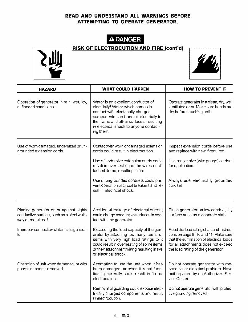
READ AND UNDERSTAND ALL WARNINGS BEFORE
ATTEMPTING TO OPERATE GENERATOR.
RISK OF ELECTROCUTION AND FIRE (cont'd)
HAZARD
Operation of generator in rain, wet, icy,or flooded conditions.
Use of worn damaged, undersized or un-grounded extension cords.
Placing generator on or against highlyconductive surface, such as a steel walk-way or metal roof.
Improper connection of items to genera-tor.
Operation of unit when damaged, or withguards or panels removed.
WHAT COULD HAPPEN
Water is an excellent conductor ofelectricity[ Water which comes incontact with electrically chargedcomponents can transmit electricity tothe frame and other surfaces, resultingin electrical shock to anyone contact-ing them.
Contact with worn or damaged extensioncords could result in electrocution.
Use of undersize extension cords couldresult in overheating of the wires or at-tached items, resulting in fire.
Use of ungrounded cordsets could pre-vent operation of circuit breakers and re-sult in electrical shock.
Accidental leakage of electrical currentcould charge conductive surfaces in con-tact with the generator.
Exceeding the load capacity of the gen-erator by attaching too many items, oritems with very high load ratings to itcould result in overheating of some itemsor their attachment wiring resulting in fireor electrical shock.
Attempting to use the unit when it hasbeen damaged, or when it is not func-tioning normally could result in fire orelectrocution.
Removal of guarding could expose elec-trically charged components and resultin electrocution.
HOW TO PREVENT IT
Operate generator in a clean, dry, wellventilated area. Make sure hands are
dry before touching unit.
Inspect extension cords before useand replace with new if required.
Use proper size (wire gauge) cordsetfor application.
Always use electrically groundedcordset.
Place generator on low conductivitysurface such as a concrete slab.
Read the load rating chart and instruc-tions on page 9, 10 and 11. Make surethat the sum mation of electrical loadsfor all attachments does not exceed
the load rating of the generator.
Do not operate generator with me-chanical or electrical problem. Haveunit repaired by an Authorized Ser-vice Center.
Do not operate generator with protec-tive guarding removed.
4 -- ENG

READ AND UNDERSTAND ALL WARNINGS BEFORE
ATTEMPTING TO OPERATE GENERATOR.
RISK OF FIRE
HAZARD
Attempting to fill the fuel tank while theengine is running.
Sparks, fire, hot objects
Improper storage of fuel
Inadequate ventilation for generator
Tampering with factory set engine speedsettings.
Overfilling the fuel tank- fuel spillage.
WHAT COULD HAPPEN
Gasoline and gasoline vapors canbecome ignited by coming in contactwith hot components such as themuffler, engine exhaust gases, or froman electrical spark.
Cigarettes, sparks, fires, or other hotobjects can cause gasoline or gasolinevapors to ignite.
Improperly stored fuel could lead to ac-cidental ignition. Fuel improperly securedcould get into the hands of children orother unqualified persons.
Materials placed against or near the gen-erator or operating the generator in ar-eas where the temperature exceeds 104°F. ambient can interfere with its properventilation features causing overheatingand possible ignition of the materials.
Engine speed has been factory set toprovide safe operation. Tampering with theengine speed adjustment could result inoverheating of attachments and couldcause a fire.
Spilled fuel and its vapors can becomeignited from hot surfaces or sparks.
HOW TO PREVENT IT
Turn engine off and allow it to coolbefore adding fuel to the tank. Equiparea of operation with a fire extin-guisher certified to handle gasolineor fuel fires.
Add fuel to tank in well ventilated area.Make sure there are no sources ofignition near the generator.
Store fuel in a container designed tohold gasoline. Store container in se-cure location to prevent use by oth-ers.
Operate generator in a clean, dry, wellventilated area a minimum of four feetfrom any objects or wall. DO NOTOPERATE UNIT INDOORS OR INANY CONFINED AREA.
Never attempt to "speedup" the en-gine to obtain more performance.Both the output voltage and frequencywill be thrown out of standard by thispractice, endangering attachmentsand the user.
Use care in filling the tank to avoidspilling fuel. Make sure fuel cap issecured tightly and check enginefor fuel leaks before starting engine.Move generator away from refuelingarea or any spillage before startingengine. Allow for fuel expansion.Keep maximum fuel level I/4inchbelow the tip of the fuel tank. Neverrefuel with the engine running.
5 -- ENG

READ AND UNDERSTAND ALL WARNINGS BEFOREATTEMPTING TO OPERATE GENERATOR.
Risk of Injury and Property Damage WhenTransporting Generator
HAZARD
Fire, Inhalation, Damage to VehicleSurfaces
WHAT COULD HAPPEN
Fuel or oil can leak or spill and couldresult in fire or breathing hazard, seri-ous injury or death can result. Fuel or oilleaks will damage carpet, paint or othersurfaces in vehicles or trailers.
HOW TO PREVENT IT
If generator is equipped with a fuelshut-off valve, turn the valve to theoff position before transporting toavoid fuel leaks. If generator is notequipped with a fuel shut-off valve,drain the fuel from tank before trans-porting. Only transport fuel in an CSAapproved container. Always placegenerator on a protective mat whentransporting to protect against dam-age to vehicle from leaks. Removegenerator from vehicle immediatelyupon arrival at your destination
RISK OF BREATHING - INHALATION HAZARD
HAZARD
Gasoline engines produce toxic carbonmonoxide exhaust fumes.
WHAT COULD HAPPEN
Breathing exhaust fumes will cause se-rious injury or death.
HOW TO PREVENT IT
Operate generator in clean, dry, wellventilated area. Avoid enclosed areas
like garages, basements, storagesheds, etc., which lack a steady ex-change of air. Never operate unit in alocation occupied by humans or ani-mals. Keep children, pets and othersaway from area of operating unit.
6 -- ENG

READ AND UNDERSTAND ALL WARNINGS BEFOREATTEMPTING TO OPERATE GENERATOR.
RISK OF UNSAFE OPERATION
HAZARD
Operation of generator in carelessmanner.
Operation of voltage sensitive applianceswithout a voltage surge protector.
WHAT COULD HAPPEN
All sources of energy include the poten-tial for injury. Unsafe operation or main-tenance of your generator could lead toserious injury or death to you or others.
Any gasoline operated household gen-erator wilt incur voltage variations caus-ing damage to voltage sensitive appli-ances or result in fire.
HOW TO PREVENT IT
Review and understand all of theoperating instructions and warn-ings in this manual.Become fam iliar with the operationand controls of the generator.Know how to shut it off quickly.Equip area of operation with a fireextinguisher certified to handlegasoline or fuel fires.Keep children or others away fromthe generator at all times.
Always use U.L listed voltage pro-tector to connect voltage sensitiveappliances (TV, computer, stereo,etc.). Failure to use a U.L listed volt-age surge protector will void the war-ranty on your generator.
Notice: A multiple outlet strip is nota surge protector make sure you usea U.L listed voltage surge protector.
RISK OF HOT SURFACES
HAZARD
Contact with hot engine and generatorcomponents.
HAZARD
Contact with moving parts can result inserious injury.
WHAT COULD HAPPEN
Contact with hot surfaces, such as en-gines exhaust corn ponents, could resultin serious burns.
HOW TO PREVENT IT
During operation, touch only the con-trol surfaces of the generator. Keepchildren away from the generator atall times. They may not be able torecognize the hazards of this prod-uct.
RISK OF MOVING PARTS
WHAT COULD HAPPEN
The generator contains parts which ro-tate at high speed during operation.These parts are covered by guarding toprevent injury.
HOW TO PREVENT IT
Never operate generator with guard-ing or cover plates removed. Avoidwearing loose fitting clothing or jew-elry which could be caught by mov-ing parts.
7 -- ENG

READ AND UNDERSTAND ALL WARNINGS BEFOREATTEMPTING TO OPERATE GENERATOR.
HAZARD
Lifting a very heavy object.
RISK FROM LIFTING
WHAT COULD HAPPEN
Serious injury can result from attempt-ing to lift too heavy an object.
HOW TO PREVENT IT
The generator is too heavy to be liftedby one person. Obtain assistancefrom others before you try to move it.
Read Owner's Manual. Do not operate equipment until you have read Owner's Manual for Safety,Operation, and Maintenance Instructions.
This product is not equipped with a spark arresting muffler. If the product will be used around flammable materials, or onland covered with materials such as agricultural crops, forest, brush, grass, or other similar items, then an approved sparkarrester must be installed and is legally required in the state of California. It is a violation of California statutes section130050 and/or sections 4442 and 4443 of the California Public Resources Code, unless the engine is equipped with a sparkarrester, as defined in section 4442, and maintained in effective working order. Spark arresters are also required on someU.S. Forest Service land and may also be legally required under other statutes and ordinances.
Engine exhaust contains chemicals known, in certain quantities, to cause cancer, birth defects or other reproductive harm.
CARTON CONTENTS
• Main Unit
• Owner's Manual
• Wheels
• Handle
• Wheel BracketOwner's Manual
_ W_heels
(2 used)
Lock Nuts
(2 used)
Washer
(2 used)
Ha_ndle Should<rBolts (2 used)
/ ,so,.tor Foo,Foot Bracket 0
Handle Cap(2 used)
I AUTION: Read owner's manual. Do not attempt tooperate equipment until you have read Owner's Manualfor Safety, Operation, and Maintenance Instructions.
REMOVE GENERATOR FROM CARTON
• Open carton from top.
• Cut carton along dotted lines.
• Remove all carton inserts.
Remove generator through opening in carton.
Remove shipping block from under the gen headby unscrewing the bolt and remove the wood block.It is very important that this is removed before startingyour generator.
8 -- ENG

IMPORTANT: Before any attempt to start your generatorbe sure to check engine oil (See OPERATION underAdding Engine Oil on page 12.)
GROUNDING THE GENERATOR
This generator should be grounded to help preventaccidental electrical shock. Shown below is a picture ofthe grounding lug supplied on your generator. First, drivea 3/4" or 1" diameter copper pipe or rod into the groundclose to the generator set. The pipe must penetrate moistearth. Using #10 gauge wire, connect one end of the wireinto the grounding lug. Next, connect the other end of thewire to the copper pipe or rod using an approved groundclamp.
Grounding Lug
INSTALLING WHEEL KIT
The Sears Wheel Kit was designed to greatly improve theportablility of your generator. You will need (2) 1/2"wrenches and (2) 9/16" wrenches.
• Place two 4"x4" pieces of wood on the floor. Withanother person helping, carefully lift the generator andplace on top of the wood supports. This will supportthe weight of the gasoline engine and generator whilethe wheels, brackets, and handle are installed. Also, itwill allow access to the underside of the generator forhardware installation. Fuel tank should be drainedprior to installation. Make sure that the generator issupported evenly, level and will not fall.
• Place a handle cap (7) onto each end of handle priorto installation.
• The handle should be installed on the electrical outletend of the generator. Place one washer (12) on longcap screws (11). Align the handle brackets with theupper holes pre-drilled in the generator frame. Placementioned screws through frame and handle brackets.Secure with lock nuts (8) and tighten.
• Locate the engine support. Place one wheel bracket(4) on top of support as shown in illustration below.Align with the pre-drilled holes in support. Place 2 capscrews (9) through holes in bracket and support.Secure with 2 lock nuts (8) and tighten.
• Insert one shoulder bolt (2) into wheel (1). Insertthreaded end of bolt through wheel bracket, securewith lock nut (3) and tighten. Note: The wheel willnot rub frame if installed properly.
• Repeat the above steps for the opposite side.
• Insert the threaded stud of rubber foot (10) through themiddle hole of the foot bracket (5). Secure with locknut (8)and tighten.
• Locate the support under the electrical outlet end ofthe generator. Position foot bracket (5), with rubberfoot installed, under the support and align the holesin the foot bracket (5) with the slots in the support.Place one cap screw (9) through each slot in thesupport and the holes in the foot bracket. Secure withthe lock nuts (8)and tighten.
• Once completed, the wheel kit is ready for use.
This portability kit includes the following parts:
KeyNo. Description PART NO.
1 Wheel (2 used) AC-00142 Shoulder Bolt (2 used) CAC-603 Lock Nut 3/8"-16 (2 used) SSF-8111 -ZN4 Wheel Bracket (2 used) GS-05615 Foot Bracket GS-05626 Handle GS-05647 Handle Cap (2 used) GS-05658 Lock Nut 5/16"-18 (9 used) SSF-81509 Cap Screw 5/16"-18 x 3/4"
(7 used) SS-12-CD10 Isolator Foot GS-058711 Cap Screw 5/16-18 x 1.75"
(2 used) SSF-999-112 Washer (2 used) SS-6506-CD
//
/
1112
10
9 -- ENG

KNOW YOUR GENERATOR
Read this Owner's Manual and Safety Rules be-fore operation of your Generator, Compare thisillustration with your generator to familiarize yourselfwith the location of various controls and adjustments.Save the manual for future references.
FUEL TANK- Capacity of 7 US gallons.
CHOKE SWITCH- Lever used to start cold engine.
ENGINE RUN/STOP SWITCH- Sets engine in startingmode for recoil starter - Stops running engine.
ENGINE OIL FILL- Place where engine oil is poured.
CIRCUIT BREAKER- Each receptacle has a circuitbreaker to protect the generator from overloading.
120 VOLT RECEPTACLES- Used to supply 2400 watts ofelectrical power per receptacles. Protected by 20 amp cir-cuit breaker.
240 VOLT TWISTLOCK RECEPTACLE- Used to
supply 5250 watts of electrical power per receptacle foroperations. Protected by 20 amp circuit breaker.
AIR CLEANER- Includes filter element and foampre-cleaner that limits the amount of dirt that entersthe engine,
FUEL CAP
FUELTANK
ENGINE RUN/STOPSWITCH
120 VOLT
10 -- ENG

RECEPTACLES
Your generator is equipped with duplex 120 volt receptaclesand a twistlock 240 volt receptacle.
The unit is also equipped with a 20 amp circuit breaker forthe 120 volt receptacles and a 20 amp circuit breaker forthe 240 volt receptacle which is provided to protect thegenerator against electrical overload. If the circuit breakertrips, unplug electrical load from receptacle. Let circuitbreaker cool down and then push circuit breaker button toreset.
o® 1@ @
120V 20A
120V 20A
cD@
@120/240V 20A
@
GENERATOR CAPACITY
Exceeding the rated capacity of your generator canresult in serious damage to your generator and connectedelectrical devices. You should observe the following toprevent overloading the unit:
• Starting and running wattage requirements must becalculated to match your generator wattage capacity.
Resistive load appliances such as light bulbs, TV'sand microwaves, have the same starting and runningwattage. The wattage used for calculating the capacitycan usually be found on each of these appliances.
Some inductive appliances and tools will list on the motorname plate, the starting and running voltage and amperagerequirements. Use the following formula to convert voltageand amperage to wattage:
(Volts X Amp = Watts)
Inductive load appliances and tools such as refrigerators,air compressors and washers require approximately 2 to4 times the listed running wattage for starting the equip-ment. This initial load only lasts for a few seconds onstart-up but is very important when figuring your totalwattage to be used.
NOTE: Always start your largest electric motor first, andthen plug in other items, one at a time.
The guide below is provided to assist you in determiningthe appliances and tools that can be ran with the wattagecapacity of your generator.
I!
OBTAINING ELECTRICITY FROM
GENERATOR
There are basically two ways to obtain electricity form agenerator:
• Use of extension cords directly form the generatorto the appliance, lights, tools, etc.
• Use of a double-throw transfer switch installed
directly to the main electrical supply outside of thehouse.
Extension Cord
When using an appliance or tool at a considerable distancefrom the generator, a 3-wire extension cord that has a3-blade grounding plug and 3-slot receptacle that acceptsthe tool's plug should be used. A cord of adequate sizemust be used. A minimum of 12 gauge wire size with atleast a 20 amp draw can be used. When amperageexceeds 20 amps a 10 gauge wire size should be used.
11 -- ENG

Connecting Generator To Main Electrical
Supply
Potential hazards exist when a electrical generator is con-nected to the main electrical supply coming into the house.It is at that point that the generator could feed back into theutility company's system causing possible electrocution ofworkers who are repairing electrical lines. To avoid backfeeding of electricity into utility systems, a double-throwtransfer switch should be installed between the genera-tor and utility power. This device should be installed by alicensed electrician and in compliance with all local electri-cal codes.
NOTE: When installing a Double-ThrowTransfer Switch,a minimum of 10 gauge wiring must be used.
BEFORE STARTING ENGINE
I CAUTION: Always check engine oil level beforeevery start. Running engine low of oil or out of oilcould result in serious damage to the engine.
Adding Engine Oil
Your generator has been shipped without oil in theengine. Begin by removing the oil dipstick and plug. Startpouring the oil in slowly.
The engine will hold approximately 26 ounces of oil. Tocheck the oil, clean and replace the dipstick. Do notscrew the dip stick in when checking the oil level. Next,remove the dipstick to check the level. The oil dipstick isclearly marked with lines that tell you when the enginehas enough oil. Do not fill above this point.
CLEAN
DIPSTICK
NOTE: When adding oil to the engine crankcase, use ahigh quality detergent oil classified "For Service SF,SG,SH"rated SAE 30 weight. Use no special additives. Select theoil's viscosity grade according to your expected operatingtemperatures.
SAE Viscosity Grades
I T
TARTI NG TEMPERATLIR1E RANGE_ANTICIPATED BEFORE NEXT_IL CHANGE
Low Oil Shutdown
Your Sears generator engine is equipped with Low OilShutdown. Low Oil Shutdown is a safety device de-signed to protect your engine from damage in theevent the oil level in the crankcase is low.
If while the engine is running, the oil gets low, it willautomatically shut itself down and will not restart until theoil is added. If the oil is low before start-up, the genera-tor will not start until oil is added.
NOTE: The Low Oil Shutdown mechanism is very sensi-tive. You must fill the engine to the full mark on the dipstickto inactivate this safety device.
Gasoline
Your generator engine is 4 cycle. Use unleaded fuel only.Never mix oil with gasoline.
CAUTION: Never fill fuel tank completely. Fill tank to1/2" below the bottom of the filler neck to providespace for fuel expansion. Wipe any fuel spillage fromengine and equipment before starting engine.
I WARNING: Never fill fuel tank indoors. Never fill fuel Itank when engine is running or hot. Do not smoke Iwhen filling fuel tank.
Use clean, fresh, regular unleaded gasoline with a mini-mum of 85 octane. Do not mix oil with gasoline. If unleadedfuel is not available, leaded fuel may be used.
To Start Your Generator
I CAUTION: Never run engine indoors or in enclosed, I
I
poor ventilated areas. Engine exhaust contains car-lbon monoxide, an ordorless and deadly gas.
Make sure the fuel shutoff valve is turned to the openposition.
CLOSE
OPEN__
• Remove gas cap.
• Add unleaded gasoline, slowly, to fuel tank.
• Do not overfill.
• On the engine there is a start/off switch locatedon the front panel of the engine. Place this switch tothe start position.
12 -- ENG

• On the engine there is a choke/run lever. Place thislever to the choke position.
FULL CHOKE POSITION
S_ CHOKE LEVER*,_ NO CHOKE
• Grasp the starter handle and pull rope out slowlyuntil it pulls harder. Let the rope rewind slowly.Then pull rope with a rapid full arm stroke. Let ropereturn to starter slowly.
• When engine starts, gradually move choke lever to"No Choke Position".
• If the engine fails to start after (3) pulls, move thechoke lever to the beginning choke position and pullstart rope again.
• For hot engine starts make sure choke lever is in the"No Choke Position".
Connecting Electrical Loads
• Let engine run and warm up for about five minutesafter starting.
• Plug in the desired 120 or 240 volts tools.
• DO NOT connect 240 volt equipment to the 120 voltduplex receptacles.
• DO NOT connect 3-phase loads to the panelreceptacles.
IMPORTANT: You should always add up the ratedwatts of all lights, tools and appliances you are power-ing at one time. This total should not exceed the ratedcapacity of you generator or circuit breaker rating ofthe receptacle supplying power.
Stopping The Engine
• Disconnect all electrical loads.
• Switch the start/off switch to the off position.
.......STOp _
IMPORTANT: Never store engine with fuel in tank,indoors, or in enclosed, poorly ventilated areas or wherefuel fumes may reach an open flame.
CUSTOMER RESPONSIBILITIES TABLE
MAINTNENANCE TASK
Before eachuse
Every 25Hours of EverySeason
Every 50Hours of EverySeason
Check oil level X See Note 2
Change oil See Note 1
Clean Air Filter Assembly X
Check Spark Plug X
Prepare Unit for Storage
Every 100Hours of EverySeason
x
Prepare unit for storage if it is to remain idle for more than 30 days.
Note 1: Change oil after first two (2) operating hours and every 50 operating hours thereafter, more often if operated inextreme dusty or dirty conditions.
Note 2: Check oil after 5 hours of operation (See page 14 - ENGINE MAINTENANCE - Oil.)
13 -- ENG

GENERAL RECOMMENDATIONS
The warranty of the generator does not cover items thathave been subjected to operator abuse or negligence. Toreceive full value from the warranty, operator must maintainthe generator as instructed in this manual.
Some adjustments will need to be made periodically tomaintain your generator.
GENERATOR MAINTENANCE
Your generator should be kept clean and dry at all times.The generator should not be stored or operated inenviroments that include excessive moisture, dust or anycorrosive vapors. If these substances are on the generator,clean with a cloth or soft bristle brush. Do not use a gardenhose or anything with water pressure to clean the genera-tor. Water may enter the cooling air slots and could possi-bly damage the rotor, stator and the internal windings of thegen head.
All adjustments in the Maintenance section of this manualshould be made at least once each season.
ENGINE MAINTENANCE
Oil
• Oil level should be checked prior to each use and atleast every 5 hours of operation. To check oil seeAdding Engine Oil on page 12.
Changing Engine OilFor a new engine, change oil after the first 2 operatinghours. Thereafter, change oil after every 50 hours ofoperation.
Change the oil while the engine is still warm. The oil willflow freely and carry away more impurities. Make sure theengine is level when filling, checking or changing oil.
Change the oil as follows:
• To keep dirt, grass clippings, etc. out of the engine,clean the area around the drain plug and dipstickbefore removing it.
Remove the oil drain plug and dipstick. Tilt theengine slightly towards the oil drain to obtain betterdrainage. Be sure to allow ample time for completedrainage.
OIL DRAIN
OIL DRAIN
PLUG
OIL FILL
Reinstall the drain plug. Make sure it is tightenedsecurely.
• Fill the crankcase with new oil of the proper type (SeeAdding Oil Section), to the Full mark on the dipstick.Always check the level with the dipstick before addingmore oil.
• Reinstall the oil fill cap or plug and tighten securely.
Service Air Cleaner
NOTE: Do not use petroleum solvents, e.g., kerosene,which will cause the cartridge to deteriorate. Do not usepressurized air to clean cartridge. Pressurized air candamage the cartridge.
To service air cleaner follow these steps:
1. Unscrew wing nut. Remove cover and air cleanercartridge.
2. Remove cartridge from cover.
To service cartridge, clean by tapping gently on a flatservice. Do not oil cartridge. Replace if dirty or damaged.
3. Replace air cleaner cartridge. Place cover over cartridgeand tighten nut finger tight and then turn it one morecomplete turn.
PAPER FILTER
___Wl cOVER
BASE NG NUT
Clean Guard/Muffler
Do not clean with a forceful spray of water becausewater could contaminate fuel system. With a brushor cloth clean finger guard after every use to preventengine damage caused by overheating.
CLEAN
14 -- ENG

Before running engine, clean muffler area to removeall combustible debris.
CLEAN
Clean and Replace Spark Plug
Change the spark plug every 100 hours of operation oronce each year, whichever comes first. This will helpyour engine to start easier and run better.
.030" (0.76MM)WIRE GAUGE
RESISTOR
Carburetor
The carburetor of your generator is pre-set at the factory.The carburetor should not be tampered with. If your gen-erator is used at an altitude in excess of 4000 feet perfor-mance may be affected. If so consult with your nearestSears Service Center regarding high altitude set changes.
Governor
Your engine governor maintains the constant operatingspeed of your generator. DO NOT tamper with the enginegovernor which is factory set for proper engine speed.
Over-speeding your engine above factory high speed set-ting can be dangerous and could possibly cause personalinjury or property damage. If you believe the engine is run-ning too fast or slow, take your generator to a AuthorizedSears Service Center for repair and adjustment.
I CAUTION: Low engine speeds impose a heavy load Ion the engine and when sufficient power is not avail- Iable the engine life could be shortened.
Ifyou are going to store your generator for more than 30days, use the following information as a guide to preparethe generator for storage.
STORAGE INSTRUCTIONS
CAUTION: Never store generator with fuel in thetank indoors or in enclosed, poorly ventilated areas,where fumes can reach an open flame, spark or pilotlight as on a furnace, water heater, clothes dryer orother gas appliances.
Engine Preparation
• Add fuel stabilizer to fuel tank to minimize theformation of fuel gum deposits during storage.
• Run engine at least 10 minutes after adding stabilizerto allow it to enter the fuel system.
• Next shut off engine.
• Disconnect the spark plug wire and remove thespark plug.
• Add one teaspoon of oil through the spark plug hole.
• Place rag over spark plug hole and pull the recoil afew times to lubricate the combustion chamber.
• Replace the spark plug, but do not connect the sparkplug wire.
NOTE: If a fuel stabilizer is not used, all gasoline mustbe drained from the tank and carburetor to prevent gumdeposits from forming on these parts and causingpossible malfunction of the engine.
Generator
• Clean the generator as outlined on Page 14 (GeneratorMaintenance)
• Check that cooling air slots and openings on generatorare open and unobstructed.
15 -- ENG

PROBLEM
Engine will not start
No electrical output
Repeated circuit breaker tripping
Generator overheating
CAUSE
No auto idle
DC does not have power with the
circuit breaker depressed
1. Low on fuel or oil.
2. Ignition switch in "Off" position.
3. Faulty spark plug.
4. Choke in wrong position.
5. Fuel shut-off valve in closedposition.
6. Unit loaded during start-up.
7. Spark plug wire loose.
1. Faulty receptacle.
2. Circuit breaker kicked out.
3. Defective capacitor.
4. Faulty power cord.
5. GFCI switch breaker kicked out (ifequipped)
1. Overload2. Faulty cords or equipment.
1. Generator overloaded.
2. Insufficient ventilation.
1. Faulty solenoid
2. Faulty idle control switch
3. Faulty windings in stator
4. Faulty circuit board
5. Faulty wire harness
1. Faulty rectifier
2. Faulty windings in stator
3. Faulty wire harness
CORRECTION
1. Add fuel or oil.
2. Turn to "ON" position
3. Replace spark plug.
4. Adjust choke accordingly.
5. Open fuel shut-off valve.
6. Remove load from unit.
7. Attach wire to spark plug.
1. Have Service Center replace.
2. Depress and reset.
3. Have Service Center replacecapacitor.
4. Repair or replace cord.
5. Depress and reset
1=
2.Reduce load.
Check for damaged, bare, orfrayed wires on equipment.Replace.
1. Reduce load.
2. Move to adequate supply offresh air.
1. Have Service Center replace.
2. Have Service Center replace.
3. Have Service Center replace.
4. Have Service Center replace.
5. Have Service Center replace
1. Have Service Center replace.
2. Have Service Center replace.
3. Have Service Center replace.
16 -- ENG

CRAFTSMAN 5250 GENERATOR 919.327210
TORQUE 20-25 IN.-LBS.
(NOT SHOWN)
20-25 IN.-LBS.
16
TOQUE 120-144 IN.-LBS.
KEYNO.123456789101112131415161718192O21222324252627
1 20TORQUE 60-70 IN.-LBS,
TORQUE12
TORQUE 120-144 IN.-LBS.
DESCRIPTIONFUEL TAN K SCREWSFUEL TANKFUEL CAPFUEL HOSEFUEL LINE CLAMPDRAINCOCK GROMMETTANK DRAINCOCKENDCOVERSCREW #10-24 x 9/16ISOLATORWASHER 3/8LOCK NUT 3/8-16GROUND LUGSCREW 5/16-18 x 3/4SCREW 3/8-16 x 1LOCK NUT 5/16-18SCREW, HEX HEAD 5/16-18LOCK WASH ERGROUND STRAPHEX SCREW 3/8-16X2.5ENGINEFRAME ASSEMBLYHEAT SHIELDSCREW 5/16-18 X 3/4WASHER TYPE A-WSPACER ENGINEWASHER .8750D .3751 D .083THK
96-120 IN.-LBS.
PART NUMBER91895680GS-0444GS-0443GS-0225GS-0227GS-0446GS-0437GS-0077SSF-553-1GS-0033SSN-1014-ZNSSF-8111 -ZNGS-0117SS-12-CDSSF-3140-ZNSSF-8150SSF-999-1SSN-1619-ZNGS-0118SSF-628GS-0501GS-0467GS-0432-1SSF-3152SSN-60-ZNGS-0746SSN-632
17 -- ENG

CRAFTSMAN 5250 GENERATOR 919.327210
SHOWN FORREFERENCE ONLY
29 ORIENT WiTH VENTS DOWNWARDAS SHOWN
30 31 TORQUE TO 204--264 IN-LBS
TORQUE UNTIL THREADS RUN OUT
38 39 TORQUETO 60-70 IN-LBS
32 34 35
TORQUE TO 120-144-IN-LBS
TORQUE TO 30-40 IN-LBS
CAPACITORWiRiNGSCALE 1:1
SHOWN FORREFERENCE ONLY
KEYNO.293O31323334353637383g4O4142
DESCRIPTIONDRIVE END ADAPTERLOCKWASHER 3/8CAP SCREW 5/16 - 24XlROTOR ASSEMBLYSTATOR THRU BOLTSTATOR ASSEMBLYWASHER 11/16OD x 11/32NUT 5/16-24ROTOR THRU BOLTBEARING SUPPORTHEX NUT 1/4-20CAPACITORCAPACITOR BRACKETSCREW 10 - 24 x g/16
PART NUMBERGS-0511SS-1503-CDSSF-616-ZNGS-0588GS-0110GS-058gSS-6506-CDSSF-576GS-00g1-1GS-0521SSF-575GS-05g2GS-0595SSF-553-1
ITEM NOT SHOWN*DIODES GS-0082

CRAFTSMAN 5250 GENERATOR 919.327210
46
O
47 4849
44
43 51
KEYNO. DESCRIPTION43 120V/20A DUPLEX RECEPTACLE44 4 PRONG TWlSTLOCK45 CIRCUIT BREAKER 120/240V/20A46 SCREW #6 - 32 x .5 TORX47 NUT, 10 - 9 X .50 PLASTITE48 SWITCH FACE PLATE RESET49 NUT, HEX JAM 7/1650 SPEED NUT #6 - 3251 WAS HER 3/8
PART NUMBERGS-0019GS-0445GS-0025SSF-583SSF-3156GS-0207SSF-595SSF-584SS-1525-CD

CRAFTSMAN 5250 GENERATOR 919.327210 TECUMSEH 4-CYCLE ENGINE MODEL #HM100-159409P
/87
7069
82
264A ,..,'VII
I1_''136II I
240 242 /250
/246
112
111
113
370G
262
285370K
"--. /
// 287
390
/_110
370L/
/261282
_' 281 \_
20 -- ENG

CRAFTSMAN 5250 GENERATOR 919.327210 TECUMSEH 4-CYCLE ENGINE MODEL #HM10O-159409P
RERNO. PARTNO.1 35968A2 2765215 30699C15A 3070015B 65049416 33454A17 2991618 65102820 3531925 3646025A 3624425B 65105926 65056128 3032230 3730235 2982636 2991837 2921638 2964240 35776A40 35777A40 35778A41 35773A41 35774A41 35775A42 3577942 3578042 3578143 3577245 3689847 65103348 3403449 3689650 3537560 33273A65 65012869 35262A70 3537671 3537772 2764275 3531980 3184581 30590A82 3537883 30588A84 2989386 65083387 65083289 3258990 61109092 65088093 65088194 65101695 30886A96 30845A100 35135101 610118102 651024103 651007110 35589
110A 36993111 611220
111B 611226112 35967113 650950119 36451120 36449
DESCRIPTIONCYLINDER (INCL. #2, 20 & 72)DOWEL PINGOVERNOR ROD (INCL. #15A & 15B)GOVERNOR YOKESCREW,6-40 X 5/16"GOVERNOR LEVERGOVERNOR LEVER CLAMPSCREW,TORX T-15, 8-32 X 3/8"OIL SEALBLOWER HOUSING BAFFLEAIR BAFFLESCREW,3/8-16 X 47/64"SCREW,1/4-20 X 5/8"LOCK NUT, 8-32CRANKSHAFTSCREW,10-32 X 3/4"LOCK WASHERLOCK NUT, 10-32RETAINING RINGPISTON PIN & RING SET (STD.)PISTON PIN & RING SET (.010" OS)PISTON PIN & RING SET (.020" OS)PISTON PIN & ASS'Y (STD.) (INCL. #43)PISTON PIN & ASS'Y (.010" OS)(INCL. #43)PISTON PIN & ASS'Y (.020" OS) (INCL. #43)RING SET (STD.)RING SET (.010" OS)RING SET (.020" OS)PISTON PIN RETAINING SETCONNECTING ROD ASS'Y. (INCL. #47 & 49)CONNECTING ROD BOLTVALVE LIFTEROIL DIPPERCAMSHAFT (MCR)BLOWER HOUSING EXTENSIONSCREW,10-24 X 1/2"CYLINDER COVER GASKET (KIT)CYLINDER COVER (INCL. #71, 75 & 80)CRANKSHAFT BUSHINGOIL DRAIN PLUGOILSEALGOVERNOR SHAFTWASHERGOVERNOR GEAR ASS'Y (INCL. #81)GOVERNOR SPOOLRETAINING RINGSCREW,1/4-20 X 1-3/16"SCREW,1/4-20 X 1-11/16"FLYWHEEL KEYFLYWHEELLOCK WASHERFLYWHEEL NUTLOCK NUT, 10-32EXTENSION SPRINGR.RM. ADJUSTING BOLTSOLID STATE IGNITIONSPARK PLUG COVERSOLID STATE MOUNTING STUDSCREW,TORX T-15, 10-24 X 15/16"GROUND SCREWOIL SHUT-DOWN WIRE & TERMINALLOW OIL SHUT-DOWN SWITCH (INCL. #112)ROCKER ON/OFF SWITCHLOW OIL SHUT-DOWN GASKET (KIT)SCREW,TORX T-25, 10-24 X 5/8"CYLINDER HEAD GASKET (KIT)CYLINDER HEAD
HERNO.125125126126127128130130A135139140149149A15015116917017117217317417818218418520722322423823924O242245250251260261262264A265275276277281282285287290292296
311A312325342
370G370K370L380390
4OO
41641742O
PARTNO.27878A27880A3403534036650691650690650694A65103133636333696508362788235862278813258127896A284232842428425353506501282975230088A33263338773387865037827915A2882027272A33266332673326833269A65051336468A65078829747B65080233272B34185B315886507293301365076035985B29752309622646034279B35941296732944330063352743669536990640152590746
36452B
34479A650696730225
DESCRIPTIONEXHAUST VALVE (STD.)(INCUL. #151)EXHAUST VALVE (1/32" OS)(INCL. #151)INTAKE VALVE (STD.) (INCL. #151)INTAKEVALVE (1/32" OS) (INCL. #151)WASHERBELLEVILLE WASHERSCREW, 5/16-18 X 2"SCREW, 1/4-20 X 9/16"RESISTOR SPARK PLUG (RJ17LM)GOVERNOR GEAR BRACKETSCREW, 10-24 X 1/2"VALVESPRING CAPVALVESPRING CAPVALVE SPRINGVALVE SPRING KEEPERBREATHER GASKET (KIT)BREATHER BODYBREATHER ELEMENTVALVE COVERBREATHER TUBESCREW, 10-24 X 1/2"NUT & LOCK WASHER 1/4-28SCREW, 1/4-28 X 1"CARBURETOR TO INTAKE PIPE GASKET (KIT)INTAKE PIPETHROTTLE LINKSCREW, TORX T-3O,5/16-18 X 1-1/8"INTAKE PIPE GASKET (KIT)SCREW, 10-31 X 1/2"AIR CLEANER GASKET (KIT)AIR CLEANER BRACKETAIR CLEANER BRACKETAIR CLEANER FILTERAIR CLEANER COVERWING NUT, 1/4-20BLOWER HOUSINGSCREW 5/16-18 X 3/4"SCREW TORX T-4O,5/16 - 24 X 21/32"SCREW 1/4-20 X 5/8"CYLINDER HEAD COVERMUFFLERLOCKING PLATESCREW, 5/16 - 18 X 3 - 3/16"STARTER BUBBLE COVERSCREW, 10 - 32 X 3/8"STARTER CUPNUT & LOCK WASHER, 1/4 - 28FUEL LINEFUEL LINE CLAMP
FUEL FILTER (INCL. 292)OIL FILL RING"O" RINGWIRE CLIPSCREW,TORX T-3O,1/4 - 20 X 1/2"INSTRUCTION DECALSTARTER DECALLOW OIL DECALCARBURETOR (INCL. 184)REWIND STARTER(NOTE: THIS ENGINE COULD HAVE BEENBUILT WITH 590704 STARTER).GASKET SET(INCL. ITEMS MARKED PK IN NOTES)INCL. PART # 27272A, 27896A, 27915A,29673, 33263, 33629, 34698A, 35262A,35317, 36451SPARK ARRESTOR KIT (INCL. 417) (OPTIONAL)SCREW, 5/16 - 18 X 2 - 45/64"SAE 30 4-CYCLE ENGINE OIL (QUART)
21 -- ENG
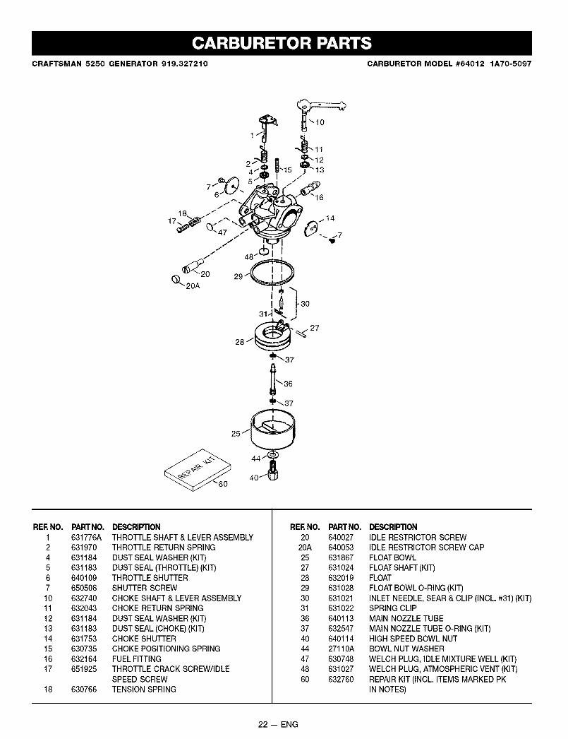
CRAFTSMAN 5250 GENERATOR 919.327210 CARBURETOR MODEL #64012 1A70-5097
REE NO.1245671011121314151617
18
PARTNO.631776A631970631184631183640109650506632740632043631184631183631753630735632164651925
630766
DESCRIPTIONTHROTTLE SHAFT & LEVERASSEMBLYTHROTTLE RETURN SPRING
DUST SEAL WASHER (KIT)DUST SEAL (THROTTLE)(KIT)THROTTLE SHUTTERSHUTTER SCREWCHOKE SHAFT & LEVERASSEMBLYCHOKE RETURN SPRING
DUST SEAL WASHER (KIT)DUST SEAL (CHOKE) (KIT)CHOKE SHUTTERCHOKE POSITIONING SPRINGFUELFITTINGTHROTTLE CRACK SCREW/IDLESPEED SCREWTENSION SPRING
REE NO. PARTNO.20 640027
20A 64005325 63186727 63102428 63201929 63102830 63102131 63102236 64011337 63254740 64011444 27110A47 63074848 63102760 632760
DESCRIPTIONIDLE RESTRICTOR SCREWIDLE RESTRICTORSCREW CAPFLOAT BOWL
FLOAT SHAFT(KIT)FLOATFLOAT BOWL O-RING (KIT)INLET NEEDLE,SEAR & CLIP (INCL. #31) (KIT)SPRING CLIPMAIN NOZZLE TUBE
MAIN NOZZLE TUBE O-RING (KIT)HIGH SPEED BOWL NUTBOWL NUT WASHER
WELCH PLUG, IDLE MIXTURE WELL (KIT)WELCH PLUG, ATMOSPHERIC VENT (KIT)REPAIR KIT (INCL. ITEMS MARKED PKIN NOTES)
22 -- ENG

CRAFTSMAN 5250 GENERATOR 919.327210 STARTER #590745
--11
13 12
6j 6
RERNO.12345678111213
PARTNO.590599A590600590679590601590678590680590412590681590747590535590701
DESCRIPTION
SPRING PIN (INCL. 4)WASHERRETAINERWASHERBRAKE SPRINGSTARTER DOGDOG SPRINGPULLEY & REWIND SPRING ASSEMBLYSTARTER HOUSING ASSEMBLY
STARTER ROPE (LENGTH 98" X 9/64" DIA.)STARTER HANDLE
23 -- ENG

CALIFORNIA & US EPA EMISSION CONTROL WARRANTY STATEMENT
The U. S. Environmental Protection Agency ("EPA"), the California Air Resources Board ("CARB") and Tecumseh Products Co.are pleased to explain the Federal and California Emission Control Systems Warranty on your new utility or lawn and gardenequipment engine. In California, new 1995 and later utility and lawn and garden equipment engines must be designed, built andequipped to meet the State's stringent anti-smog standards. In other states, new 1997 and later model year engines must bedesigned, built and equipped, at the time of sale, to meet the U.S. EPA regulations for small non-road engines. TecumsehProducts Co. will warrant the emission control system on your utility or lawn and garden equipment engine for the periods of timelisted below, provided there has been no abuse, neglect, unapproved modification, or improper maintenance of your utility or lawnand garden equipment engine.
Your emission control system may include parts such as the carburetor, ignition system and exhaust system. Also included maybe the compression release system and other emission-related assemblies.
Where a warrantable condition exists, Tecumseh Products Co. will repair your utility or lawn and garden equipment engine at no
cost to you for diagnosis, parts and labor.
MANUFACTURER'S EMISSION CONTROL SYSTEM WARRANTY COVERAGE
Emission control systems on 1995 and later model year California utility and lawn and garden equipment engines are warrantedfor two years as hereinafter noted. In other states, 1997 and later model year engines are also warranted for two years. If, duringsuch warranty period, any emission-related part on your engine is defective in materials or workmanship, the part will be repairedor replaced by Tecumseh Products Co.
OWNER'S WARRANTY RESPONSIBILITIES
As the utility or lawn and garden equipment engine owner, you are responsible for the performance of the required maintenancelisted in your Owner's Manual, but Tecumseh Products Co. will not deny warranty solely due to the lack of receipts or for yourfailure to provide written evidence of the performance of all scheduled maintenance.
As the utility or lawn and garden equipment engine owner, you should, however, be aware that Tecumseh Products Co. maydeny you warranty coverage if your utility or lawn and garden equipment or a part thereof has failed due to abuse, neglect,improper maintenance or unapproved modifications.
You are responsible for presenting your utility or lawn and garden equipment engine to a Tecumseh Authorized Service Outlet(any Tecumseh Registered Service Dealer, Tecumseh Authorized Service Distributor or Tecumseh Central Warehouse Distribu-tor) as soon as a problem exists. The warranty repairs should be completed in a reasonable amount of time, not to exceed 30days.
Warranty service can be arranged by contacting either a Tecumseh Authorized Service Outlet or by contacting TecumsehProducts Co., c/o Service Manager, Engine and Transmission Group Service Division, 900 North Street, Grafton, Wl 53024-1499.Telephone 1-414-377-2700, or see your local telephone yellow pages under "Engines, Gasoline" for the name, address andtelephone number of a Tecumseh Authorized Service Outlet near you.
IMPORTANT NOTE
This warranty statement explains your rights and obligations under the Emission Control System Warranty ("ECS Warranty")which is provided to you by Tecumseh Products Co. pursuant to California law. Tecumseh Products Co. also provides to odginalpurchasers of new Tecumseh Products Co. engines. The Tecumseh Products Co. Limited Warranties for New Tecumseh Engineand Electronic Ignition Modules ("Tecumseh Products Co. Warranty') Which is enclosed with all new Tecumseh Products Co.engines on a separate sheet. The ECS Warranty applies only to the emission control system of your new engine. To the extentthat there is any conflict in terms between the EC$ Warranty and the Tecumseh Products Co. Warranty, the ECS Warranty shallapply except in any circumstances in which the Tecumseh Products Co. Warranty may provide a longer warranty period. Boththe ECS Warranty and the Tecumseh Products Co. Warranty describe important rights and obligations with respect to your newengine.
Warranty service can only be performed by a Tecumseh Products Co. Authorized Service Outlet, or by Tecumseh Products Co.at its factory in Grefton, Wl. At the time of requesting warranty service, evidence must be presented of the date of sale to theoriginal purchaser. The purchaser shall pay any charges for making service cells and/or for transporting the products to and fromthe place where the inspection and/or warranty work is performed. The purchaser shall be responsible for any damage or lossincurred in connection with the transportation of any engine or any part(s) thereof submitted for inspection and/or warranty work.
If you have any questions regarding your warranty dghts and responsibilities, you should contact Tecumseh Products Co. at1-414-377-2700.
24 -- ENG

EMISSION CONTROL SYSTEM WARRANTY
Emission Control System Warranty ('ECS Warranty') for 1995 and later model year California utility and lawn and garden equip-ment engines (for other states, 1997 and later model year engines):
A. APPLICABILITY: This warranty shall apply to 1995 and later model year California utility and lawn and garden equipmentengines (for other states, 1997 and later model year engines). The ECS Warranty Period shall begin on the date the newengine or equipment is delivered to its original, end-use purchaser, and shall continue for 24 consecutive months thereafter.
B. GENERAL EMISSIONS WARRANTY COVERAGE: Tecumseh Products Co. warrants to the original, end-use purchaser ofthe new engine or equipment and to each subsequent purchaser that each of its utility and lawn and garden equipmentengines is:
1. Designed, built and equipped so as to conform with all applicable regulations adopted by the Air Resources Board pursuantto its authodty in Chapters 1 and 2, Part 5, Division 26 of the Health and Safety Code, and
2. Free from defects in materials and workmanship which, at any time during the ECS Warranty Period, will cause a warrantedemissions-related part to fail to be identical in all material respects to the part as described in the engine manufacturer'sapplication for certification.
C. The ECS Warranty only pertains to emissions-related parts on your engine, as follows:
1. Any warranted emissions-related parts which are not scheduled for replacement as required maintenance in the Owner'sManual shall be warranted for the ECS Warranty Period. If any such part fa s dur ng the ECS Warranty Per od, it shall berepaired or replaced by Tecumseh Products Co. according to Subsection 4 below. Any such part repaired or replacedunder the ECS Warranty shall be warranted for any remainder of the ECS Warranty Period.
.
3,
4,
Any warranted, emissions-related part which is scheduled only for regular inspection as specified in the Owner's Manualshall be warranted for the ECS Warranty Period. A statement in such written instructions to the effect of "repair or replaceas necessary" shall not reduce.the ECSWarranty Period. Any such part repaired or replaced under the ECS Warrantysha be warranted for the remainder of the ECS Warranty Period.
Any warranted, emissions-related part which is scheduled for replacement as required maintenance in the Owner's Manual,shall be warranted for the period of time prior to the first scheduled replacement point for that part. If the part fails prior tothe first scheduled replacement, the part shall be repaired or replaced by Tecumseh Products Co. according to Subsection4 below. Any such emissions-related part repaired or replaced under the ECS Warranty, shall be warranted for the remain-der of the ECS Warranty Period prior to the first scheduled replacement point for such emissions-related part.
Repair or replacement of any warranted, emissions-related part under this ECS Warranty shall be performed at no charge tothe owner at a Tecumseh Au[h_ri_ed S_rvice Outlet. -
5.
6.
7.
8.
9_
The owner shall not be charged for diagnostic labor which leads to the determination that a part covered by the ECSWarranty is in fact defective, provided that such diagnostic work is performed at a Tecumseh Authorized Service Outlet,
Tecumseh Products Co. shall be liable for damages to other original engine components or approved modifications proxi-mately caused by a failure under warranty of an emission-related part covered by the ECS Warranty.
Throughout the ECS Warranty Period, Tecumseh Products Co. shall maintain a supply of warranted emission-related partssufficient to meet the expected demand for such emission-related pads.
Any Tecumseh Products Co. authorized and approved emission-related replacement part may be used in the performanceof any ECS Warranty maintenance or repair and will be provided without charge to the owner. Such use shall not reduceTecumseh Products Co. ECS Warranty obligations.
Unapproved add-on or modified parts may not be used to modify or repair a Tecumseh Products Co. engine. Such usevoids this ECS Warranty and shall be sufficient grounds for disallowing an ECS Warranty claim. Tecumseh Products Co.shall not be liable hereunder for failures of any warranted parts of a Tecumseh Products Co. engine caused by the use ofsuch an unapproved add-on or modified part.
EMISSION-RELATED PARTS INCLUDE THE FOLLOWING:
2_
3.
Carburetor Assembly and its Internal Componentsa) Fuel filterb) Carburetor gasketsc) Intake pipe
Air Cleaner Assemblya) Air filter element
Ignition System, including:a) Spark plugb) Ignition module
4. Catalytic Muffler (if so equipped)a) Muffler gasket (if so equipped)b) Exhaust manifold (if so equipped)
5. Crankcase Breather Assembly and its Componentsa) Breather connection tube
25 -- ENG

For in-home major brand repair service:
Call 24 hours a day, 7 days a week
1-800-4-MY-HOME TM(1-800-469-46631Para pedir servicio de reparacion a domicillo m 1-800-676-5811
In Canada for all your service and parts needs call1-800-665-4455
Au Canada pour tout le service ou les pieces
For the repair or replacement parts you need:
Call 6 am - 11 pm CST, 7 days a week
PartsDirectTM
1-800-366-PART (1-800-366-7278)
Para ordenar piezas con entrega a domicillo -- 1-800-1659-7084
For the location of a Sears Parts and Repair Center in your area:
Call 24 hours a day, 7 days a week
1-800-488-1222
For information on purchasing a Sears Maintenance Agreement
or to inquire about an existing Agreement:
Call 9 am _ 5 pm, Monday _ Saturday
1-800-827-6655
HomeCentraF