OWNER’S MANUAL AND SERVICE GUIDE - Carrus Carts … · Fig. 6 Horn Switch ... Headlight...
50
ELECTRIC POWERED THREE WHEEL SERVICE VEHICLE ISSUED APRIL 2005 OWNER’S MANUAL AND SERVICE GUIDE 29175-G01
Transcript of OWNER’S MANUAL AND SERVICE GUIDE - Carrus Carts … · Fig. 6 Horn Switch ... Headlight...

ELECTRIC POWERED THREE WHEELSERVICE VEHICLE
ISSUED APRIL 2005
OWNER’S MANUALAND SERVICE GUIDE
29175-G01

SAFETYRead and understand all labels located on the vehicle. For any questions on any of the information, contact a represen-tative for clarification.
Always replace any damaged or missing labels.
On steep hills it is possible for vehicles to coast at greater than normal speeds encountered on a flat surface. To pre-vent loss of vehicle control and possible serious injury, speeds should be limited to no more than the maximum speedon level ground. (See vehicle specification.) Limit speed by applying the service brake.
Catastrophic damage to the drive train components due to excessive speed may result from driving the vehicle abovespecified speed. Damage caused by excessive speed may cause a loss of vehicle control, is costly, is consideredabuse and will not be covered under warranty.
If the vehicle is to be used in a commercial environment, signs similar to the ones illustrated should be used to warn ofsituations that could result in an unsafe condition.
Be sure that this manual remains as part of the permanent service record should the vehicle be resold.
WASH HANDSAFTER HANDLING!
Battery posts,terminals and relatedaccessories contain
lead and lead compounds,chemicals known
to cause cancer andreproductive harm.
BATTERY WARNING
WASH HANDSAFTER HANDLING!
WARNING: Battery posts, terminals and relatedaccessories contain lead and lead compounds,
chemicals known to cause cancer and reproductive harm.
BATTERIESCONTAIN LEAD
AND RELATED PARTS
NOTES, CAUTIONS AND WARNINGS
Throughout this guide NOTE, CAUTION and WARNINGwill be used.
A NOTE indicates a condition that should beobserved.
A CAUTION indicates a condition thatmay result in damage to the vehicle.
A WARNING indicates ahazardous condition thatcould result in severe
injury or death.
Please observe these NOTES, CAUTIONS and WARN-INGS; be aware that servicing a vehicle requiresmechanical skill and a regard for conditions that could behazardous. Improper service or repair may damage thevehicle or render it unsafe.
Battery posts, terminalsand related accessoriescontain lead and lead
compounds. Wash hands after handling.! !
! !
(NOTES, CAUTIONS AND WARNINGS CONTINUED ON INSIDE OF BACK COVER)

Cushman Division of TEXTRON, Inc. reserves thmation contained in this manual is subject to cha
Cushman Division of TEXTRON, Inc. is not liablthis manual.
TO CONTACT US
NORTH AMERICA: TECHNICAL ASSISTANCE & WAR SERVICE PARTS PHONE: 1-888
INTERNATIONAL: PHONE: 010-1-706-798-4311, FAX
CUSHMAN DIVISION OF TEXTRO
OWNER’S MANUALAND SERVICE GUIDE
ELECTRIC POWEREDTHREE WHEEL
SERVICE VEHICLE
CUSHMAN MINUTE MISER™
Starting Model Year 2004
Page iOwner’s Manual and Service Guide
e right to make design changes without obligation to make these changes on units previously sold and the infor-nge without notice.
e for errors in this manual or for incidental or consequential damages that result from the use of the material in
RANTY PHONE: 1-800-774-3946, FAX: 1-800-448-8124-GET-EZGO (1-888-438-3946), FAX: 1-800-752-6175
: 010-1-706-771-4609
N, INC., 1451 MARVIN GRIFFIN ROAD, AUGUSTA, GEORGIA USA 30906-3852
NOTES
To obtain a copy of the limited warranty applicable to the vehicle, call or write a local Distributor, an authorized Branch or the Warranty Department with vehicle serial number
and manufacturer code.
The use of non Original Equipment Manufacturer (OEM) parts may void the warranty.
Overfilling of batteries may void the warranty.
BATTERY PROLONGED STORAGE
All batteries will self discharge over time. The rate of self discharge varies depending on theambient temperature and the age and condition of the batteries.
A fully charged battery will not freeze in winter temperatures unless the temperature falls below -75° F (-60° C).
For winter storage, the batteries must be clean, fully charged and disconnected from any source of electrical drain, such as the battery charger. Disconnect the battery charger cable
from the vehicle batteries when not charging.
As with all electric vehicles, the batteries must be checked and recharged as required or at a minimum of 30 day intervals.
Refer to the ‘Prolonged Storage’ section within the BATTERIES AND CHARGING section of this manual.
Page ii Owner’s Manual and Service Guide
TABLE OF CONTENTS
GENERAL .................................................................................................................................vii
GENERAL OPERATION ...........................................................................................................vii
MAINTENANCE ....................................................................................................................... viii
VENTILATION ............................................................................................................................ix
GENERAL ..................................................................................................................................xi
STANDARDS AND PUBLICATIONS ......................................................................................... 1Standards ............................................................................................................................................................1Publications .........................................................................................................................................................1
BEFORE INITIAL USE ............................................................................................................... 2Fig. 1 Initial Service Chart ......................................................................................................................2
On Board Charger ...............................................................................................................................................2
IDENTIFICATION ....................................................................................................................... 2Fig. 2 Model Number, Model Year and Serial Number .........................................................................2
CONTROLS, METERS AND SWITCHES .................................................................................. 2Fig. 3 Serial Numbers Under Seat ........................................................................................................3Fig. 4 Controls On Dashboard ...............................................................................................................3Fig. 5 Controls On Floorboard ..............................................................................................................3Fig. 6 Horn Switch ................................................................................................................................3
Key Switch ...........................................................................................................................................................3Fig. 7 Key Switch ..................................................................................................................................4
Direction Selector Switch .....................................................................................................................................4Fig. 8 Direction Selector Switch .............................................................................................................4
Power ON/Battery Condition Meter .....................................................................................................................4Headlight (Accessory) ..........................................................................................................................................4Service/Parking Brake Pedal ...............................................................................................................................4
Fig. 9 Speed Control Pedal ...................................................................................................................4Speed Control Pedal ............................................................................................................................................5Horn and Handlebar ............................................................................................................................................5Handlebar Installation ..........................................................................................................................................5Seat Switch ..........................................................................................................................................................5
Fig. 10 Seat Switch ...............................................................................................................................5Hour Meter (Accessory) .......................................................................................................................................5
ADDITIONAL FEATURES .......................................................................................................... 5Battery Charger ...................................................................................................................................................5Fold Down Backrest .............................................................................................................................................6
Fig. 11 Battery Charger ........................................................................................................................6Fig. 12 Fold Down Backrest ..................................................................................................................6
Programmable Speed Controller .........................................................................................................................6
EE UNITS ................................................................................................................................... 6
BEFORE ENTERING VEHICLE ................................................................................................. 6
OPERATING THE VEHICLE ...................................................................................................... 6
STARTING THE VEHICLE ......................................................................................................... 7
COASTING ................................................................................................................................. 7
OPERATION .............................................................................................................................. 7
DRIVING THE VEHICLE ............................................................................................................ 8
SERVICING THE ELECTRIC VEHICLE .................................................................................... 9
TOWING ..................................................................................................................................... 9
Page iiiOwner’s Manual and Service Guide

Page iv
TABLE OF CONTENTS
LIFTING THE VEHICLE .............................................................................................................9
SAFETY COMPONENTS .........................................................................................................10Seat Switch ....................................................................................................................................................... 10Thermal Circuit Breaker .................................................................................................................................... 10
Fig. 13 Lifting the Vehicle .................................................................................................................... 10Parking The Vehicle .......................................................................................................................................... 10
Fig. 14 Parking The Vehicle ............................................................................................................... 10
ROUTINE MAINTENANCE ......................................................................................................10
REAR AXLE ..............................................................................................................................11Checking the Lubricant Level ............................................................................................................................ 11
Fig. 15 Lubrication Points .................................................................................................................... 11Fig. 16 Rear Axle Lubricant Check and Fill ......................................................................................... 11
BRAKES ...................................................................................................................................11Test Method ...................................................................................................................................................... 11
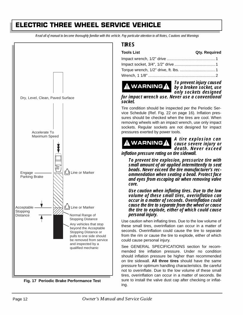
Fig. 17 Periodic Brake Performance Test ........................................................................................... 12
TIRES .......................................................................................................................................12Tire Repair ........................................................................................................................................................ 13Wheel Installation .............................................................................................................................................. 13
Fig. 18 Wheel Installation .................................................................................................................... 13Fig. 19 Wheel Installation .................................................................................................................... 13
LIGHT BULB REPLACEMENT .................................................................................................14
CARE AND CLEANING OF THE VEHICLE .............................................................................14
TRAILERING ............................................................................................................................14
HARDWARE .............................................................................................................................15Fig. 20 Bolt Grades ............................................................................................................................. 15
TORQUE SPECIFICATIONS ..................................................................................................15Fig. 21 Torque Specifications .............................................................................................................. 15
PERIODIC SERVICE SCHEDULE ..........................................................................................16Fig. 22 Periodic Service Schedule ...................................................................................................... 16
BATTERIES AND CHARGING .................................................................................................18Safety ................................................................................................................................................................ 18
BATTERY .................................................................................................................................18
BATTERY MAINTENANCE ......................................................................................................18At Each Charging Cycle .................................................................................................................................... 19Monthly ............................................................................................................................................................. 19Electrolyte Level and Water .............................................................................................................................. 19
Fig. 23 Correct Electrolyte Level ......................................................................................................... 19Fig. 24 Water Purity Table .................................................................................................................. 19Fig. 25 Automatic Watering Gun ......................................................................................................... 19
Cleaning Batteries ............................................................................................................................................. 19Fig. 26 Preparing Acid Neutralizing Solution ....................................................................................... 19
Battery Replacement ........................................................................................................................................ 19Fig. 27 Battery Connections ................................................................................................................ 20
Prolonged Storage ............................................................................................................................................ 20Fig. 28 Freezing Point of Electrolyte ................................................................................................... 20
Battery Charging ............................................................................................................................................... 21AC Voltage ........................................................................................................................................................ 21
TROUBLESHOOTING ..............................................................................................................22Hydrometer ....................................................................................................................................................... 22Using A Hydrometer .......................................................................................................................................... 23
Owner’s Manual and Service Guide

TABLE OF CONTENTS
Fig. 29 Hydrometer ..............................................................................................................................23Fig. 30 Hydrometer Temperature Correction .......................................................................................23Fig. 31 Factory Settings .......................................................................................................................30Fig. 32 Wiring Diagram ........................................................................................................................32Fig. 32 Wiring Diagram ........................................................................................................................33
GENERAL SPECIFICATIONS ................................................................................................. 29
ELECTRIC POWERED THREE WHEEL SERVICE VEHICLE ................................................ 30Fig. 33 Vehicle Dimensions and Incline Specifications ........................................................................31Fig. 34 Vehicle Turning Clearance Diameter and Intersecting Aisle Clearance ..................................32
Page vOwner’s Manual and Service Guide

Page vi
TABLE OF CONTENTS
Notes:
Owner’s Manual and Service Guide
SAFETY INFORMATION
This manual has been designed to assist the owner-operator in maintaining the vehicle in accordance with proceduresdeveloped by the manufacturer. Adherence to these procedures and troubleshooting tips will ensure the best possibleservice from the product. To reduce the chance of personal injury and/or property damage, the following instructionsmust be carefully observed:
Certain replacement parts can be used independently and/or in combination with other accessories to modify an E-Z-GO-manufactured vehicle to permit the vehicle to operate at or in excess of 20mph. When an E-Z-GO-manufacturedvehicle is modified an any way by the Distributor, Dealer or customer to operate at or in excess of 20mph, UNDERFERERAL LAW the modified product will be a Low Speed Vehicle (LSV) subject to the strictures and requirements ofFederal Motor Vehicle Safety Standard 571.500. In these instances, pursuant to Federal law the Distributor or DealerMUST equip the product with headlights, rear lights, turn signals, seat belts, top, horn and all other modifications forLSV’s mandated in FMVSS 571.500, and affix a Vehicle Identification Number to the product in accordance with therequirements of FMVSS 571.565. Pursuant to FMVSS 571.500, and in accordance with the State laws applicable in theplaces of sale and use of the product, the Distributor, Dealer or customer modifying the vehicle also will be the FinalVehicle Manufacturer for the LSV, and required to title or register the vehicle as mandated by State law.
E-Z-GO will NOT approve Distributor, Dealer or customer modifications converting E-Z-GO products into LSV’s.
The Company, in addition, recommends that all E-Z-GO products sold as personal transportation vehicles BE OPER-ATED ONLY BY PERSONS WITH VALID DRIVERS LICENSES, AND IN ACCORDANCE WITH APPLICABLE STATE REQUIREMENTS. This restriction is important to the SAFE USE AND OPERATION of the product. On behalf of E-Z-
GO, I am directing that E-Z-GO Branch personnel, Distributors and Dealers advise all customers to adhere to this SAFETY RESTRICTION, in connection with the use of all products, new and used, the Distributor or Dealer has rea-
son to believe may be operated in personal transportation applications.
Information on FMVSS 571.500 can be obtained at Title 49 of the Code of Federal Regulations, section 571.500, orthrough the Internet at the website for the U.S. Department of Transportation - at Dockets and Regulation, then to Title49 of the Code of Federal Regulations (Transportation).
GENERAL
Many vehicles are used for a variety of tasks beyond the original intended use of the vehicle; therefore it is impossibleto anticipate and warn against every possible combination of circumstances that may occur. No warnings can take theplace of good common sense and prudent driving practices.
Good common sense and prudent driving practices do more to prevent accidents and injury than all of the warningsand instructions combined. The manufacturer strongly suggests that the owner-operator read this entire manual payingparticular attention to the CAUTIONS and WARNINGS contained therein. It is further recommended that employeesand other operators be encouraged to do the same.
If you have any questions, contact your closest representative or write to the address on the back cover of this publica-tion, Attention: Product Service Department.
E-Z-GO Division of TEXTRON Inc., reserves the right to make design changes without obligation to make thesechanges on units previously sold and the information contained in this manual is subject to change without notice.
E-Z-GO Division of TEXTRON Inc., is not liable for errors in this manual or for incidental or consequential damagesthat result from the use of the material in this manual.
Owner’s Manual and Service Guide Page vii

SAFETY INFORMATION
P
This vehicle conforms to the current applicable standard for safety and performance requirements.
These vehicles do not conform to Federal Motor Vehicle Safety Standards and are not equipped for operation on publicstreets.
With electric powered vehicles, be sure that all electrical accessories are grounded directly to the battery (-) post.Never use the chassis or body as a ground connection.
Refer to GENERAL SPECIFICATIONS for vehicle seating capacity.
Never modify the vehicle in any way that will alter the weight distribution of the vehicle, decrease its stabilityor increase the speed beyond the factory specification. Such modifications can cause serious personal injuryor death. Modifications that increase the speed and/or weight of the vehicle will extend the stopping distance and mayreduce the stability of the vehicle. Do not make any such modifications or changes. The manufacturer prohibits anddisclaims responsibility for any such modifications or any other alteration which would adversely affect the safety of thevehicle.
GENERAL OPERATION
Always use the vehicle in a responsible manner and maintain the vehicle in safe operating condition.
Always read and observe all warnings and operation instruction labels affixed to the vehicle.
Always follow all safety rules established in the area where the vehicle is being operated.
Always reduce speed to compensate for poor terrain or conditions.
Always apply service brake to control speed on steep grades.
Always maintain adequate distance between vehicles.
Always reduce speed in wet areas.
Always use extreme caution when approaching sharp or blind turns.
Always use extreme caution when driving over loose terrain.
Always use extreme caution in areas where pedestrians are present.
MAINTENANCE
Always maintain your vehicle in accordance with the manufacturer’s periodic service schedule.
Always ensure that mechanics performing repairs are trained and qualified to do so.
Always follow the manufacturer’s directions if you do any maintenance on your vehicle. Be sure to disable the vehiclebefore performing any maintenance. Disabling includes removing the key from the key switch and removal of a batterywire.
Always insulate any tools used within the battery area in order to prevent sparks or battery explosion caused by short-ing the battery terminals or associated wiring. Remove the batteries or cover exposed terminals with an insulatingmaterial.
Owner’s Manual and Service Guideage viii

SAFETY INFORMATION
Always check the polarity of each battery terminal and be sure to rewire the batteries correctly.
Always use specified replacement parts. Never use replacement parts of lesser quality.
Always use recommended tools.
Always determine that tools and procedures not specifically recommended by the manufacturer will not compromisethe safety of personnel nor jeopardize the safe operation of the vehicle.
Always support the vehicle using wheel chocks and safety stands. Never get under a vehicle that is supported by ajack. Lift the vehicle in accordance with the manufacturer’s instructions.
Never attempt to maintain a vehicle in an area where exposed flame is present or persons are smoking.
Always be aware that a vehicle that is not performing as designed is a potential hazard and must not be operated.
The manufacturer cannot anticipate all situations, therefore people attempting to maintain or repair the vehicle musthave the skill and experience to recognize and protect themselves from potential situations that could result in severepersonal injury or death and damage to the vehicle. Use extreme caution and, if unsure as to the potential for injury,refer the repair or maintenance to a qualified mechanic.
Always test drive the vehicle after any repairs or maintenance. All tests must be conducted in a safe area that is free ofboth vehicular and pedestrian traffic.
Always replace damaged or missing warning, caution or information labels.
Always keep complete records of the maintenance history of the vehicle.
VENTILATION
Hydrogen gas is generated in the charging cycle of batteries and is explosive in concentrations as low as 4%. Becausehydrogen gas is lighter than air, it will collect in the ceiling of buildings necessitating proper ventilation. Five airexchanges per hour is considered the minimum requirement.
Never charge a vehicle in an area that is subject to flame or spark. Pay particular attention to natural gas or propanegas water heaters and furnaces.
Always use a dedicated circuit for each battery charger. Do not permit other appliances to be plugged into the recepta-cle when the charger is in operation.
Chargers must be installed and operated in accordance with charger manufacturers recommendations or applicableelectrical code (whichever is more restrictive).
Owner’s Manual and Service Guide Page ix

Owner’s Manual and Service Guide
SAFETY INFORMATION
Page x
Notes:

SAFETY INFORMATIONRead all of manual to become thoroughly familiar with this vehicle. Pay particular attention to all Notes, Cautions and Warnings
GENERALThe following text is provided as recommended by part IIof ASME/ANSI B56.8-1988. The manufacturer stronglyendorses the contents of this specification.
PART IIFOR THE USER
4 GENERAL SAFETY PRACTICES
4.1 Introduction
4.1.1 Like other machines, carriers can cause injuryif improperly used or maintained. Part II contains broadsafety practices applicable to carrier operations. Beforeoperation, the user shall establish such additional spe-cific safety practices as may reasonably be required forsafe operation.
4.2 Stability
4.2.1 Experience has shown that this vehicle, whichcomplies with this standard, is stable when properlyoperated and when operated in accordance with specificsafety rules and practices established to meet actualoperating terrain and conditions. However, improperoperation, faulty maintenance, or poor housekeepingmay contribute to a condition of instability and defeat thepurpose of the standard. Some of the conditions whichmay affect stability are failure of the user to follow safetypractices; also, ground and floor conditions, grade,speed, loading, the operation of the carrier with improperloads, battery weight, dynamic and static forces, and thejudgement exercised by the carrier operator.
(a) The user shall train carrier operators to adherestrictly to the operating instructions stated in this Stan-dard.
(b) The user shall survey specific operating conditionsand environment, and establish and train carrier opera-tors to comply with additional, specific safety practices.
4.3 Nameplates, Markings, Capacity, and Modifica-tions
4.3.1 The user shall maintain in a legible conditionall nameplates, warnings, and instructions which aresupplied by the manufacturer.
4.3.2 The user shall not perform any modification oraddition which affects capacity or safe operation, ormake any change not in accordance with the owner’s
manual without the manufacturer’s prior written authori-zation. Where authorized modifications have been made,the user shall ensure that capacity, operation, warning,and maintenance instruction plates, tags, or decals arechanged accordingly.
4.3.3 As required under paras. 4.3.1 or 4.3.2, themanufacturer shall be contacted to secure new name-plates, warnings, or instructions which shall then beaffixed in their proper place on the carrier.
4.4 Fuel Handling and Storage
4.4.1 The user shall supervise the storage and han-dling of liquid fuels (when used) to be certain that it is inaccordance with appropriate paragraphs of ANSI/NFPA505 and ANSI/NFPA 30.
4.4.2 Storage and handling of liquefied petroleumgas fuels shall be in accordance with appropriate para-graphs of ANSI/NFPA 505 and ANSI/NFPA 58. If suchstorage or handling is not in compliance with these stan-dards, the user shall prevent the carrier from being useduntil such storage and handling is in compliance withthese standards.
4.5 Changing and Charging Storage Batteries forElectric Personnel and Burden Carriers
4.5.1 The user shall require battery changing andcharging facilities and procedures to be in accordancewith appropriate paragraphs of ANSI/NFPA 505.
4.5.2 The user shall periodically inspect facilitiesand review procedures to be certain that appropriateparagraphs of ANSI/NFPA 505, are strictly compliedwith, and shall familiarize carrier operators with it.
4.6 Hazardous Locations
4.6.1 The user shall determine the hazard classifi-cation of the particular atmosphere or location in whichthe carrier is to be used in accordance with ANSI/NFPA505.
4.6.2 The user shall permit in hazardous areas onlythose carriers approved and of the type required byANSI/NFPA 505.
4.7 Lighting for Operating Areas
4.7.1 The user, in accordance with his responsibilityto survey the environment and operating conditions, shalldetermine if the carrier requires lights and, if so, shallequip the carrier with appropriate lights in accordancewith the manufacturer’s recommendations.
Page xiOwner’s Manual and Service Guide

SAFETY INFORMATIONRead all of manual to become thoroughly familiar with this vehicle. Pay particular attention to all Notes, Cautions and Warnings
4.8 Control of Noxious Gases and Fumes
4.8.1 When equipment powered by internal com-bustion engines is used in enclosed areas, the atmo-sphere shall be maintained within limits specified in theAmerican Conference of Governmental IndustrialHygienists publication, “Threshold Limit Values forChemical Substances and Physical Agents in the Work-room Environment”. This shall be accomplished by venti-lation provided by the user, and/or the installation, use,and proper maintenance of emission control equipmentrecommended or provided by the manufacturer of theequipment.
4.9 Warning Device(s)
4.9.1 The user shall make periodic inspections ofthe carrier to be certain that the sound-producing and/orvisual device(s) are maintained in good operating condi-tion.
4.9.2 The user shall determine if operating condi-tions require the carrier to be equipped with additionalsound-producing and/or visual devices and be responsi-ble for providing and maintaining such devices, in accor-dance with the manufacturer’s recommendations.
5 OPERATING SAFETY RULES AND PRACTICES
5.1 Personnel and Burden Carrier Operator Qualifications
5.1.1 Only persons who are trained in the properoperation of the carrier shall be authorized to operate thecarrier. Operators shall be qualified as to visual, auditory,physical, and mental ability to safely operate the equip-ment according to Section 5 and all other applicableparts of this Standard.
5.2 Personnel and Burden Carrier Operator’s Training
5.2.1 The user shall conduct an operator’s trainingprogram.
5.2.2 Successful completion of the operator’s train-ing program shall be required by the user before opera-tion of the carrier. The program shall be presented in itsentirety to all new operators and not condensed for thoseclaiming previous experience.
5.2.3 The user should include in the operators’ train-ing program the following:
(a) instructional material provided by the manufac-
turer;
(b) emphasis on safety of passengers, material loads,carrier operator, and other employees;
(c) general safety rules contained within this Standardand the additional specific rules determined by the userin accordance with this Standard, and why they were for-mulated;
(d) introduction of equipment, control locations andfunctions, and explanation of how they work when usedproperly and when used improperly, and surface condi-tions, grade, and other conditions of the environment inwhich the carrier is to be operated;
(e) operational performance tests and evaluationsduring, and at completion of, the program.
5.3 Personnel and Burden Carrier Operator Responsibility
5.3.1 Operators shall abide by the following safetyrules and practices in paras. 5.4, 5.5, 5.6, and 5.7.
5.4 General
5.4.1 Safeguard the pedestrians at all times. Do notdrive carrier in a manner that would endanger anyone.
5.4.2 Riding on the carrier by persons other than theoperator is authorized only on personnel seat(s) providedby the manufacturer. All parts of the body shall remainwithin the plan view outline of the carrier.
5.4.3 When a carrier is to be left unattended, stopcarrier, apply the parking brake, stop the engine or turnoff power, turn off the control or ignition circuit, andremove the key if provided. Block the wheels if machineis on an incline.
5.4.4 A carrier is considered unattended when theoperator is 25 ft. (7.6 m) or more from the carrier whichremains in his view, or whenever the operator leaves thecarrier and it is not within his view. When the operator isdismounted and within 25 ft. (7.6 m) of the carrier still inhis view, he still must have controls neutralized, and theparking brake(s) set to prevent movement.
5.4.5 Maintain a safe distance from the edge oframps and platforms.
5.4.6 Use only approved carriers in hazardous loca-tions, as defined in the appropriate safety standards.
5.4.7 Report all accidents involving personnel,building structures, and equipment.
5.4.8 Operators shall not add to, or modify, the car-rier.
Page xii Owner’s Manual and Service Guide

SAFETY INFORMATIONRead all of manual to become thoroughly familiar with this vehicle. Pay particular attention to all Notes, Cautions and Warnings
5.4.9 Carriers shall not be parked or left unattendedsuch that they block or obstruct fire aisles, access tostairways, or fire equipment.
5.5 Traveling
5.5.1 Observe all traffic regulations, including autho-rized speed limits. Under normal traffic conditions keepto the right. Maintain a safe distance, based on speed oftravel, from a carrier or vehicle ahead; and keep the car-rier under control at all times.
5.5.2 Yield the right of way to pedestrians, ambu-lances, fire trucks, or other carriers or vehicles in emer-gency situations.
5.5.3 Do not pass another carrier or vehicle travel-ing in the same direction at intersections, blind spots, orat other dangerous locations.
5.5.4 Keep a clear view of the path of travel,observe other traffic and personnel, and maintain a safeclearance.
5.5.5 Slow down or stop, as conditions dictate, andactivate the sound-producing warning device at crossaisles and when visibility is obstructed at other locations.
5.5.6 Ascend or descend grades slowly.
5.5.7 Avoid turning, if possible, and use extremecaution on grades, ramps, or inclines; normally travelstraight up and down.
5.5.8 Under all travel conditions the carrier shall beoperated at a speed that will permit it to be brought to astop in a safe manner.
5.5.9 Make starts, stops, turns, or direction rever-sals in a smooth manner so as not to shift the load,endanger passengers, or overturn the carrier.
5.5.10 Do not indulge in dangerous activities, such asstunt driving or horseplay.
5.5.11 Slow down when approaching, or on, wet orslippery surfaces.
5.5.12 Do not drive carrier onto any elevator unlessspecifically authorized to do so. Approach elevatorsslowly, and then enter squarely after the elevator car isproperly leveled. Once on the elevator, neutralize thecontrols, shut off power, and set parking brakes. It isadvisable that all other personnel leave the elevatorbefore a carrier is allowed to enter or exit.
5.5.13 Avoid running over loose objects, potholes,and bumps.
5.5.14 To negotiate turns, reduce speed to improvestability, then turn hand steering wheel or tiller in a
smooth, sweeping motion.
5.6 Loading
5.6.1 Handle only stable and safely arranged loads.When handling off-center loads which cannot be cen-tered, operate with extra caution.
5.6.2 Handle only loads within the capacity of thecarrier as specified on the nameplate.
5.6.3 Handle loads exceeding the dimensions usedto establish carrier capacity with extra caution. Stabilityand maneuverability may be adversely affected.
5.7 Operator Care of Personnel and Burden Carriers
5.7.1 At the beginning of each shift during which thecarrier will be used, the operator shall check the carriercondition and inspect the tires, warning devices, lights,battery(s), speed and directional controllers, brakes, andsteering mechanism. If the carrier is found to be in needof repair, or in any way unsafe, the matter shall bereported immediately to the designated authority and thecarrier shall not be operated until it has been restored tosafe operating condition.
5.7.2 If during operation the carrier becomes unsafein any way, the matter shall be reported immediately tothe designated authority, and the carrier shall not beoperated until it has been restored to safe operating con-dition.
5.7.3 Do not make repairs or adjustments unlessspecifically authorized to do so.
5.7.4 The engine shall be stopped and the operatorshall leave the carrier while refueling.
5.7.5 Spillage of oil or fuel shall be carefully andcompletely absorbed or evaporated and fuel tank capreplaced before starting engine.
5.7.6 Do not operate a carrier with a leak in the fuelsystem or battery(s).
5.7.7 Do not use open flames for checking electro-lyte level in storage battery(s) or liquid level in fuel tanks.
6 MAINTENANCE PRACTICES
6.1 Introduction
6.1.1 Carriers may become hazardous if mainte-nance is neglected. Therefore, maintenance facilities,trained personnel, and procedures shall be provided.Such facilities may be on or off the premises.
Page xiiiOwner’s Manual and Service Guide

SAFETY INFORMATIONRead all of manual to become thoroughly familiar with this vehicle. Pay particular attention to all Notes, Cautions and Warnings
6.2 Maintenance Procedures
6.2.1 Maintenance and inspection of all carriersshall be performed in conformance with the manufac-turer’s recommendations and the following practices.
(a) A scheduled preventive maintenance, lubrication,and inspection system shall be followed.
(b) Only qualified and authorized personnel shall bepermitted to maintain, repair, adjust, and inspect carriers.
(c) Before undertaking maintenance or repair, followthe manufacturer’s recommendations for immobilizingthe carrier.
(d) Block chassis before working underneath it.
(e) Before disconnecting any part of the engine fuelsystem of a gasoline or diesel powered carrier with grav-ity feed fuel systems, be sure shutoff valve is closed, andrun engine until fuel system is depleted and engine stopsrunning.
(f) Before disconnecting any part of the engine fuelsystem of LP gas powered carriers, close the LP gas cyl-inder valve and run the engine until fuel in the system isdepleted and the engine stops running.
(g) Operation to check performance of the carrier shallbe conducted in an authorized area where safe clear-ance exists.
(h) Before commencing operation of the carrier, followthe manufacturer’s instructions and recommended pro-cedures.
(i) Avoid fire hazards and have fire protection equip-ment present in the work area. Do not use an open flameto check level or leakage of fuel, battery electrolyte, orcoolant. Do not use open pans of fuel or flammablecleaning fluids for cleaning parts.
(j) Properly ventilate the work area.
(k) Handle LP gas cylinders with care. Physical dam-age, such as dents, scrapes, or gouges, may danger-ously weaken the tank and make it unsafe for use.
(l) Brakes, steering mechanisms, speed and direc-tional control mechanisms, warning devices, lights, gov-ernors, guards, and safety devices shall be inspectedregularly and maintained in a safe operating condition.
(m) Special carriers or devices designed andapproved for hazardous area operation shall beinspected to ensure that maintenance preserves the orig-inal approved safe operating features.
(n) Fuel systems shall be checked for leaks and condi-tion of parts. If a leak is found, action shall be taken to
prevent the use of the carrier until the leak has beeneliminated.
(o) The carrier manufacturer’s capacity, operation,and maintenance instruction plates, tags, or decals shallbe maintained in legible condition.
(p) Batteries, motors, speed and directional control-lers, limit switches, protective devices, electrical conduc-tors, and connections shall be inspected and maintainedin conformance with manufacturers recommended pro-cedures.
(q) Carriers shall be kept in a clean condition to mini-mize fire hazards and facilitate detection of loose ordefective parts.
(r) Modifications and additions which affect capacityand safe machine operation shall not be performed bythe customer or user without manufacturer’s prior writtenauthorization; where authorized modifications have beenmade, the user shall ensure that capacity, operation,warning, and maintenance instruction plates, tags, ordecals are changed accordingly.
(s) Care shall be taken to ensure that all replacementparts are interchangeable with the original parts and of aquality at least equal to that provided in the originalequipment.
Page xiv Owner’s Manual and Service Guide

ELECTRIC THREE WHEEL SERVICE VEHICLERead all of manual to become thoroughly familiar with this vehicle. Pay particular attention to all Notes, Cautions and Warnings
STANDARDS AND PUBLICATIONSThis unit is not a motor vehicle within the definition of theNational Traffic Motor Vehicle Safety Act. It is notdesigned or manufactured for use on roads, streets, orhighways, and is not appropriate for such use. This unitis not meant to be licensed as a motor vehicle.
The Electric 3 wheel service vehicle is available as Type"E" and Type "EE" Units. Type "E" Units are electricallypowered units having minimum acceptable safeguardsagainst inherent fire hazards.Type "EE" Units have addi-tional safeguards against such hazards.
Users, operators and service persons should be familiarwith the following standards and publications:
Standards(The material may be obtained from the address shown).
• Factory Mutual Approval Standard: Class # 7820; Electric Battery Powered Trucks,Types E and EE.ADDRESS:Factory Mutual Research Corp.1151 Boston--Providence HighwayNorwood, Massachusetts 02062 USA
• National Fire Protection Association:ANSI/NFPA #505; Powered Industrial Trucks.ADDRESS:National Fire Protection AssociationBatterymarch ParkQuincy, Massachusetts 02269 USA
• ANSI/ASME B56.8Personnel and Burden CarriersADDRESS:American National Standards Institute, Inc.1430 BroadwayNew York, New York 10018 USA
• ANSI/UL 583; Electric Battery Powered IndustrialTrucksADDRESS:American National Standards Institute, Inc.1430 BroadwayNew York, New York 10018 USA
OR
Underwriters Laboratories Inc.333 Pfingsten RoadNorthbrook, Illinois 60062 USA
This Electric Vehicle complies with ANSI B56.8 as itapplies to OSHA for Powered Industrial Trucks under theType E and EE classifications. This vehicle has beenapproved by Factory Mutual Research Corporation. Tomeet the manufacturer portions of the OSHA require-ments (as stated in section 1910.178, Paragraph a3)Powered Industrial Trucks must bear the approval markof either UL (Underwriters Laboratory) or FM (FactoryMutual) or other nationally recognized testing laborato-ries.
Publications
Additional operator’s manuals and parts manuals areavailable for a minimum charge.
Parts Manual 29177-G01
Repair Manual 29178-G01
Thank you for this purchase. The vehicle is equippedwith an electronic speed control unit that is the mostadvanced in the industry. Before driving the vehicle, weask you to spend some time reading this Owner’s Man-ual and Service Guide. This guide contains informationthat will assist you in maintaining your highly reliablevehicle. Some illustrations may show items that areoptional for your vehicle.
Most of the service procedures in this guide can beaccomplished by an individual using common automotivehand tools. Refer to an authorized service representativefor information on servicing the vehicle in accordancewith the Periodic Service Schedule.
To facilitate maintenance, a Service Parts Manual and aTechnician’s Repair and Service Manual is availablefrom a local Distributor, an authorized Branch or the Ser-vice Parts Department. When ordering parts or request-ing information for your vehicle, provide vehicle model,serial number and manufacture code.
Page 1Owner’s Manual and Service Guide
ELECTRIC THREE WHEEL SERVICE VEHICLERead all of manual to become thoroughly familiar with this vehicle. Pay particular attention to all Notes, Cautions and Warnings
BEFORE INITIAL USERead, understand and follow safety label on the instru-ment panel. The vehicle has been designed to operate ina warehouse or factory environment with semi-smoothfloors, road and ramps.
Be sure you understand the vehicle, its equipment andhow to use it safely. Although the vehicle has beendesigned to provide safe and reliable operation, main-taining good performance depends to a large extent onthe operator.
Vehicle batteries must be fully charged before initial use.
Hydrogen gas is generat-ed as a natural part of thelead acid battery charg-
ing process. A 4% concentration of hydrogen gas isexplosive and could cause severe injury or death.Charging must take place in an area that is adequate-ly ventilated (minimum of 5 air exchanges per hour).
To reduce the chance of battery explosion that couldresult in severe injury or death, never smoke aroundor charge batteries in an area that has open flame orelectrical equipment that could cause an electricalarc.
Hydrogen gas is generated in the charging cycle of bat-teries and is explosive in concentrations as low as 4%.Because hydrogen gas is lighter than air, it will collect inthe ceiling of buildings necessitating proper ventilation.Five air exchanges per hour is considered the minimumrequirement.
Never charge a vehicle in an area that is subject to flameor spark. Pay particular attention to natural gas or pro-pane gas water heaters and furnaces.
Before a new vehicle is put into operation, it is recom-mended that the items listed in the INITIAL SERVICECHART be performed (Ref Fig. 1 on page 2).
On Board ChargerThe on board charger is wired directly to the batteries,only requiring it be plugged into a dedicated 15 amp ACoutlet to be operational. When charge cycle is complete,replace cord in appropriate area under cargo deck.
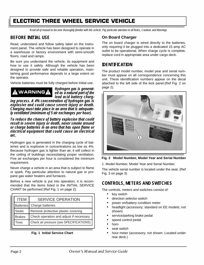
IDENTIFICATIONThe product model number, model year and serial num-ber must appear on all correspondence concerning thisunit. These identification numbers appear on the decalattached to the left side of the kick panel.(Ref Fig. 2 onpage 2).
1. Model Number, Model Year and Serial Number.
The vehicle serial number is located under the seat. (RefFig. 3 on page 3)
CONTROLS, METERS AND SWITCHESThe controls, meters and switches consist of:
• key switch• direction selector switch• power on/battery condition meter• headlight (accessory; standard on EE models; not
shown)• service/parking brake pedal• speed control pedal• horn• seat switch• hour meter (accessory; not shown. Located under
rear deck.)Fig. 1 Initial Service Chart
! !
ITEM SERVICE OPERATIONBatteries Charge batteries
Seats Remove protective plastic covering
Brakes Check operation and adjust if necessary
Tires Check air pressure (see SPECIFICATIONS)
Fig. 2 Model Number, Model Year and Serial Number
1
Page 2 Owner’s Manual and Service Guide

ELECTRIC THREE WHEEL SERVICE VEHICLERead all of manual to become thoroughly familiar with this vehicle. Pay particular attention to all Notes, Cautions and Warnings
1. Serial Numbers Under Seat.
(Ref. Fig. 4 on page 3) and (Ref. Fig. 5 on page 3) showthe controls on the dash and the floorboard.
1. Key Switch
2. Direction Selector Switch
3. Power On/Battery Condition Meter
4. Headlight Switch
1. Service/Parking Brake Pedal
2. Speed Control Pedal
(Ref Fig. 6 on page 3) shows the horn button and handle-bar.
1. Handlebar
2. Horn
Key SwitchThe key switch, located in the vehicle dash, supplies orinterrupts power to the vehicle electrical system.
Fig. 3 Serial Numbers Under Seat
Fig. 4 Controls On Dashboard
1
4
3
1 2
Fig. 5 Controls On Floorboard
Fig. 6 Horn Switch
1
2
1
2
Page 3Owner’s Manual and Service Guide

ELECTRIC THREE WHEEL SERVICE VEHICLERead all of manual to become thoroughly familiar with this vehicle. Pay particular attention to all Notes, Cautions and Warnings
ON POSITION: Supplies power
OFF POSITION: Interrupts power (Ref Fig. 7 on page 4)
1. On Position
2. Off Position
To prevent unexpectedvehicle movement oru n a u t h o r i z e d u s e ,
always turn the key switch to the OFF position andremove the key when the vehicle is not in use.
Direction Selector SwitchThe direction selector switch, located on the dash panel,controls the direction of vehicle movement. The panel ismarked with FORWARD, NEUTRAL and REVERSEpositions. Push to the NEUTRAL position when leavingthe vehicle seat.
To prevent unexpectedvehicle movement whenyou or other persons
next operate the vehicle, ALWAYS place the directionselector switch in the NEUTRAL position when leav-ing the vehicle seat.
Remove the key to prevent unauthorized use of thevehicle.
Power ON/Battery Condition MeterThe power on/battery condition meter indicates whetherpower is supplied to the unit and the state of batterycharge. The meter illuminates only when power is beingsupplied.
The meter scale is a 10--bar LED (light emitting diode)displaying the state of charge successively, bar by bar,from full to empty.
• At 70% of discharge, a flashing light signals an“energy reserve” alert.
• At 80% of discharge, a double flashing light sig-nals as “empty” alarm. The batteries should befully charged before using the vehicle.
Headlight (Accessory)The headlight can be pivoted on the mounting asrequired. Push the headlight switch on the dash panel toturn the headlight on or off.
Service/Parking Brake PedalThe service and parking brakes are combined in the leftpedal on the floorboard. Depressing the pedal will slowor stop the vehicle. Once the vehicle has stopped, theparking brake can be engaged by pressing the front por-tion of the pedal.
The floorboard catch should engage in the first notch ofthe parking brake lock catch when the brake is properlyadjusted. (Ref. Fig. 9 on page 4).
To release the parking brake, depress the service/park-ing brake pedal.
Fig. 7 Key Switch
Fig. 8 Direction Selector Switch
2
1
! !
NEUTRAL
FORWARD
REVERSE
! !
Fig. 9 Speed Control Pedal
FRONT OF VEHICLE
DEPRESS TORELEASE PARKINGBRAKE
DEPRESS TO ENGAGEPARKING BRAKE CATCH
FLOORBOARD
FLOORBOARD CATCH
PARKING BRAKELOCK CATCHFIRST NOTCH
Page 4 Owner’s Manual and Service Guide

ELECTRIC THREE WHEEL SERVICE VEHICLERead all of manual to become thoroughly familiar with this vehicle. Pay particular attention to all Notes, Cautions and Warnings
ALWAYS apply the park-ing brake when the vehi-c l e i s t o b e l e f t
unattended. The parking brake is NOT automaticallyapplied.
Speed Control PedalDepressing the speed control pedal starts the motor;releasing the pedal stops the motor.
Operation with the pedal fully depressed gives maximumspeed but is recommended only when the vehicle can beoperated safely. For slower speeds, depress the pedal asrequired.
Reverse speed is half of forward speed.
To prevent loss of vehi-c l e c o n t r o l , N E V E Rexceed safe operating
speed. ALWAYS adjust speed to conditions.
Horn and HandlebarThe horn button switch is attached to the handlebar onthe standard equipment vehicle.
A vehicle equipped with optional wheel type steering willhave the horn button located on the right side of thesteering console.
Depress the button to sound the horn. The horn will notsound when the key is in off position.
Handlebar Installation
If the handlebar is factory installed,make sure the retaining nut is tight.
Otherwise install the fork spindle key, handle, lockwasher andnut. Tighten the nut to 50 ft. lbs. (68 Nm) torque.
Failure to install the forkspindle key and to tight-en the handlebar retain-
ing nut may allow the handlebar to come loose,resulting in loss of vehicle steering control.
Seat SwitchThe seat switch, located under the operator’s seat,allows the vehicle to function only when the seat is inposition and the operator is properly seated. Should theoperator leave the seat during operation, the vehicle willstop.(Ref. Fig. 10 on page 5).
To prevent unexpectedvehicle movement, NEV-ER operate the vehicle if
the seat switch is malfunctioning.
Hour Meter (Accessory)The hour meter, located in the motor compartment,behind the speed controller, records the number of hoursthe vehicle has been operated.
ADDITIONAL FEATURESAdditional features include a built-in battery charger, afold down backrest and a programmable speed control-ler.
Battery ChargerThe standard vehicle is equipped with a built-in 24 volt,25 amp DC, 120 volt AC, 60 Hz, fully automatic charger,located under the driver’s seat. There is also a storagearea under the seat for the charger cord. (Ref Fig. 11 onpage 6).
! !
! !
! !
Fig. 10 Seat Switch
! !
Page 5Owner’s Manual and Service Guide

ELECTRIC THREE WHEEL SERVICE VEHICLERead all of manual to become thoroughly familiar with this vehicle. Pay particular attention to all Notes, Cautions and Warnings
Fold Down BackrestThe backrest is easily positioned to provide seating for apassenger or, in a raised position, for cargo.
To lower the backrest, lift it upward and toward the frontof the vehicle. When the pins on either side have clearedthe slots, slowly lower the backrest into position. Reversethe procedure when raising the backrest. (Ref Fig. 12 onpage 6).
To prevent possible inju-ry, make sure the seat isin the lowered position
when carrying a passenger. Raise the seat if no pas-senger will be carried. DO NOT allow a passenger tostand on the rear step.
Programmable Speed ControllerThe vehicle is equipped with a programmable speed con-troller, which provides a variety of diagnostic data andcan be used to change factory speed settings. For infor-mation about diagnostics, troubleshooting, adjustmentsand factory settings, see pages 27 - 30 of this manual.
EE UNITSThis vehicle is available in “EE” versions. “EE” Unitsmeet all the requirements of “E” Units and provide addi-tional safeguards against inherent fire and electrical haz-ards, as specified per U.L. 583.
The additional components used on “EE” vehiclesinclude:
• head light guard• rear light guard• terminal boots for the circuit breaker, motor, and
forward, reverse and main solenoids• a static strap• a safety hasp to keep the battery compartment
securely closed
“EE” Units function identically to “E” Units.
BEFORE ENTERING VEHICLE1. Check for correct tire inflation.
2. Inspect for fluid leaks.
3. Be sure everything is properly stored and secured.
If vehicle has built-in charger, unplug power cord fromelectrical outlet and properly store cord under instrumentpanel prior to moving vehicle. If vehicle has a portablecharger, remove charger plug from vehicle receptacleand properly store cable prior to moving vehicle.
OPERATING THE VEHICLEImproper use of the vehicle or the lackof proper maintenance may result in
decreased performance or damage to the vehicle.
Read and understand the following warnings beforeattempting to operate the vehicle:
To reduce the possibilityof severe injury or deathresulting from loss of
vehicle control, the following warnings must beobserved:
Fig. 11 Battery Charger
Fig. 12 Fold Down Backrest
2
1
COMBINATIONBACKRESTAND SEAT
SLOT
PIN
! !
! !
Page 6 Owner’s Manual and Service Guide

ELECTRIC THREE WHEEL SERVICE VEHICLERead all of manual to become thoroughly familiar with this vehicle. Pay particular attention to all Notes, Cautions and Warnings
Drive the vehicle only as fast as terrain and safetyconsiderations allow. Consider the terrain, trafficconditions and the environmental factors whicheffect the terrain and the ability to control thevehicle.Use extra care and reduced speed when drivingon poor surfaces, such as loose dirt, wet grass,gravel, etc.Avoid extremely rough terrain.Avoid driving fast down hill. A sudden stop orchange of direction may result in loss of control.Use service brake to control speed when travelingdown an incline.Slow down before and during turns. All turnsshould be executed at reduced speed.All travel should be directly up or down hills.Use extra care when driving the vehicle acrossany incline.
Stay in designated areas and avoid steep slopes. Toreduce the possibility of severe injury or death result-ing from improper vehicle operation, the followingwarnings must be observed:
Refer to GENERAL SPECIFICATIONS for capacity.Make sure that the direction selector is in correctposition before attempting to start the vehicle.Do not take vehicle out of ‘gear’ while in motion(coast).Always bring the vehicle to a complete stopbefore shifting the direction selector.Check the area behind the vehicle before operat-ing in reverse.Always hold on while the vehicle is in motion.Keep feet, legs, hands and arms inside the vehicleat all times.To prevent inadvertent movement when the vehi-cle is to be left unattended, set parking brake ped-al completely, move direction selector switch toneutral position, turn key to ‘OFF’ position andremove key.
STARTING THE VEHICLETo start the vehicle: Place the key in the key switch andturn to the ‘ON’ position. Move the direction selector to
the direction desired, release park brake and press theaccelerator pedal to start the vehicle.
When the direction selector is in the reverseposition, a warning signal will sound. This is a
device to indicate the vehicle is ready to run in reverse.
Releasing the accelerator slows the vehicle. To stop thevehicle more quickly, depress the brake pedal.
To avoid component damage, the vehi-cle must be brought to a complete stop
before shifting the direction selector switch.
Do not hold vehicle on hill by using accelerator and motor. Leav-ing motor in a stalled condition for more than 3-4 seconds willcause permanent damage to motor.
COASTINGTo prevent in jury ordeath resul t ing f romcoasting at above recom-
mended speeds, limit speed with service brake.On steep hills/ramps, it is possible for vehicles to coast atfaster than normal speeds that may be encountered on aflat surface. To prevent loss of vehicle control, speedsshould be limited to no more than the maximum speedon level ground (see GENERAL SPECIFICATIONS).Limit speed by releasing the accelerator pedal and apply-ing pressure to the heel of the pedal. Severe damage tothe drive train components due to excessive speed mayresult from driving the vehicle above specified speed.Damage caused by excessive speed may cause a lossof control, is costly, is considered abuse and will not becovered under warranty.
OPERATIONThe SAFETY WARNING decal shown is located on theupper portion of the right kick panel. All information onthe decal is of the utmost importance. This decal and allothers must remain on the vehicle.
Failure to heed thesewarnings may result inpersonal or fatal injury to
you or others and may also result in equipment andor property damages.
Before operating vehicle:Read and understand operator’s manual (locatedunder seat).
! !
! !
Page 7Owner’s Manual and Service Guide

ELECTRIC THREE WHEEL SERVICE VEHICLERead all of manual to become thoroughly familiar with this vehicle. Pay particular attention to all Notes, Cautions and Warnings
All occupants must be seated in factory approvedseats, switches spark-do not operate in explosiveor commuatible atmosphere.While operating vehicle:Keep body inside vehicle passenger must beseated and use hand holds provided.Sudden sharp turns unbalanced or top heavyloads can cause upset.Cargo must be secured to platform.Avoid sudden starts and stops to avoid unseatingof passengers.Adjust speed to conditions.Before leaving vehicle:Set direction selector to ‘OFF’ position.Turn key to vertical ‘OFF’ position and remove.If malfunction occurs, or adjustment is needed,do not use, have all work performed by authorizedpersonnel.Apply hand or foot brake-not automaticallyapplied.It is your responsibility to keep all labels (decals)and instructional literature legible and intact.Replacement labels (decals) and literature areavailable from the factory.
Your safety and the safety of others around you dependson your conscientious operation of this vehicle. Read thefollowing section carefully and thoroughly to becomefamiliar with proper operating procedures. Be sure toread and understand the following warnings beforeattempting to operate the vehicle.
DO NOT operate thisvehicle until this own-er’s manual is read and
understood.DO NOT allow untrained or unauthorized personsto operate this vehicle. NEVER allow children tooperate the vehicle.Before using the equipment, check all parts andany attachments. If a malfunction is found, do notuse the vehicle until the problem is corrected.NEVER carry more than one passenger or a pas-senger along with a cargo load. Passenger mustremain seated in rear at all times during transport.
Passengers MUST NOT stand on rear footrest.Keep both hands on steering mechanism whenever possible and keep arms and legs inside vehi-cle while moving. Passenger must use the handholds provided with the rear seat.
Be aware of object haz-ards that can impact theoperator or passenger
within the confines of the vehicle; for example, lowhanging tree branches or laterally protruding objects.
Make sure the operating area is clear of debris.Use extreme care when backing up. Make sure noone is behind you. Back the vehicle carefully at areasonable speed.NEVER use the vehicle in or near an area wherethere is explosive dust or fumes. The electricalsystem of the unit creates sparks which can igniteexplosive materials.Adjust your speed to current driving conditions.Travel directly up or down inclines. DO NOT travelacross the face of any incline, ramp, grade orslope.Avoid driving fast down hill. A sudden stop orchange of direction can result in loss of control.Use the service brake to control speed when trav-eling down an incline.NEVER overload the vehicle. See identificationdecal on kick panel for rated capacity.Position loads carefully so they cannot shift or tipover suddenly. Distribute loads evenly over therear area. Keep loads low to avoid top heaviness.
DRIVING THE VEHICLE• Make sure you are properly seated in the opera-
tor’s seat.• Make sure the direction selector switch is in the
NEUTRAL position.• Apply the parking brake, if it isn’t already applied,
by depressing the front portion of the service/park-ing brake pedal.
• Insert the key in the key switch and turn it to theON position.
• Move the direction selector switch to the desireddirection.
! !
! !
Page 8 Owner’s Manual and Service Guide

ELECTRIC THREE WHEEL SERVICE VEHICLERead all of manual to become thoroughly familiar with this vehicle. Pay particular attention to all Notes, Cautions and Warnings
If the selector is moved to the REVERSE posi-tion, a backup warning alarm will sound until
the vehicle is again placed in NEAUTRAL or FORWARD.
SERVICING THE ELECTRIC VEHICLETo prevent severe injuryor death, resulting fromimproper servicing tech-
niques, observe the following Warnings: Do not attempt any type of servicing operationsbefore reading and understanding all notes, cau-tions and warnings in this manual.Any servicing requiring adjustments to be madeto the powertrain while the motor is running mustbe made with the entire vehicle raised.
Wear eye protection when working onthe vehicle. In particular, use carewhen working around batteries, orusing solvents or compressed air.
To reduce the possibility of causing an electricalarc, which could result in a battery explosion, turnoff all electrical loads from the batteries beforeremoving any heavy gauge battery wires.To prevent the possibility of motor disintegration,never operate vehicle at full throttle for more than4 - 5 seconds while vehicle is in a “no load” condi-tion.Battery posts, terminals and related accessoriescontain lead and lead compounds. Wash handsafter handling.
It is in the best interest of both vehicle owner and servic-ing dealer to carefully follow the procedures recom-mended in this manual. Adequate preventativemaintenance, applied at regular intervals, is the bestguarantee for keeping the vehicle both dependable andeconomical.
TOWINGT h i s v e h i c l e i s n o tdesigned to be towed.
It is recommended that this vehicle be moved by placingthe entire vehicle on a trailer, flatbed truck or other suit-able transport.
LIFTING THE VEHICLETool List Qty. Required
Floor jack..................................................................... 1Jack stands ................................................................. 4Chocks ........................................................................ 4Chain hoist .................................................................. 1
Some servicing operations may require the vehicle beraised.
To prevent possible inju-ry or death resul t ingfrom a vehicle fall ing
from a jack, be sure the vehicle is on a firm and levelsurface. Never get under a vehicle while it is support-ed by a jack. Use jack stands and test the stability ofthe vehicle on the stands. Always place chocks infront and behind the wheels not being raised. Useextreme care since the vehicle is extremely unstableduring the lifting process.
Never attempt to raise the rear wheels of a threewheel vehicle without first raising the front of thevehicle and supporting on jack stands.
When lifting vehicle, position jacks andjack stands only on the areas indicated.
Due to the low ground clearance and short wheel base,the vehicle should only be raised enough to remove thefront axle or the rear wheels. Servicing that requiresaccess to the underside of the vehicle should be accom-plished by raising the front of the vehicle with a chainhoist attached to the front frame members. Always usean additional safety chain to prevent injury should thehoist malfunction.
To remove a wheel or the front axle, loosen the hard-ware. Position a jack in the location indicated and care-fully raise the front of the vehicle. Position the jack standsas shown. Use care not to place the jack or stands wherethey could interfere with wiring or linkages. Slowly lowerthe jack and test the stability of the vehicle.
To raise the rear of the vehicle, first raise the front of thevehicle as previously described and support on jackstands. Then position the jack in the position shown atthe rear of the vehicle. Carefully raise the rear of thevehicle with the jack and place two jack stands in theposition shown. Slowly lower the jack and check that thevehicle is securely supported by the jack stands beforeproceeding.
Lower the vehicle by reversing the lifting sequence.
! !
! !
! !
Page 9Owner’s Manual and Service Guide

ELECTRIC THREE WHEEL SERVICE VEHICLERead all of manual to become thoroughly familiar with this vehicle. Pay particular attention to all Notes, Cautions and Warnings
SAFETY COMPONENTS
The vehicle electrical circuit includes two protective com-ponents: a seat switch and a thermal circuit breaker.
Seat Switch
Removing body weight from the vehicle seat will causethe seat switch to interrupt electrical power to the control-ler. You must remain seated during vehicle operation.
Thermal Circuit Breaker
The thermal circuit breaker prevents overloading of thedrive motor. Should the vehicle be stopped by the open-ing of the circuit breaker, turn the vehicle off to avoid anaccidental start when the breaker resets. The breakerautomatically resets after approximately 20 seconds. Anaudible click will sound when the breaker resets.
If the circuit breaker continues to open, a problem existswithin the circuit or the vehicle is overloaded. Do notoperate the vehicle until the problem is resolved.
I f the circuit breakershould open while driv-ing on an incline, imme-
diately apply the service and parking brakes toprevent loss of vehicle control.
Parking The VehicleTo park the vehicle, complete the following steps beforeleaving the operator’s seat:
1. Stop the vehicle and move the direction selectorswitch to the NEUTRAL position.
2. Apply the parking brake.
3. Turn the key switch to the vertical OFF position andremove the key.
When parking the vehicle on an incline, thefront wheel should be curbed whenever possi-
ble. (Ref Fig. 14 on page 10).
ROUTINE MAINTENANCEThis vehicle will give years of satisfactory service, provid-ing it receives regular maintenance. Refer to the PeriodicService Schedule for appropriate service intervals (RefFig. 22 on page 16). Refer to Lubrication Points forappropriate lubrication locations (Ref Fig. 15 on page11).
Some maintenance items must be servicedmore frequently on vehicles used under severe
driving conditions.
Use maximum of three pumps of greasefor each grease fitting - Overgreasing
may damage grease seals.
Putting more than three pumps of grease in a grease fit-ting could damage grease seals and cause prematurebearing failure.
Fig. 13 Lifting the Vehicle
View from underside of vehicle
1
3
2
44
2
(See detail)
Turn wheel as shownto permit jack placement
Place jack alongthe flat edge of
footrest
Detail
Fig. 14 Parking The Vehicle
! !
Page 10 Owner’s Manual and Service Guide

ELECTRIC THREE WHEEL SERVICE VEHICLERead all of manual to become thoroughly familiar with this vehicle. Pay particular attention to all Notes, Cautions and Warnings
REAR AXLEThe only maintenance required for the first five years isthe periodic inspection of the lubricant level. The rearaxle is provided with a lubricant level check/fill pluglocated on the bottom of the differential. Unless leakageis evident, the lubricant need only be replaced after fiveyears.
Checking the Lubricant LevelWith the vehicle on level ground, clean the area aroundthe check/fill plug and remove plug (Ref Fig. 16 on page11). The correct lubricant level is just below the bottom ofthe threaded hole. If lubricant is low, add as required.Add lubricant slowly until lubricant starts to seep from thehole. Install the check/fill plug. In the event that the lubri-cant is to be replaced, the vehicle must be elevated andthe oil pan removed or the oil siphoned out through thecheck/fill hole.
BRAKESService brakes in accordance with the Periodic ServiceSchedule (Ref Fig. 22 on page 16). After the vehicle hasbeen put into service, it is recommended that the brakesbe checked by performing the following test:
Test Method
To prevent severe injuryor death resulting fromoperating a vehicle with
improperly operating brake system, the braking sys-tem must be properly maintained. All driving braketests must be done in a safe location with regard forthe safety of all personnel.
Over time, a subtle loss of performance maytake place. Therefore, it is important to estab-
lish the normal braking distance with a new vehicle.
Determine the braking performance of the vehicle byengaging the parking brake at a common point on a flat,dry, clean paved surface while traveling at maximumspeed (Ref Fig. 17 on page 12). Observe the vehiclestopping location. If the vehicle stops in a significantlygreater distance than normal or pulls to one side, itshould be tested again.
If the vehicle fails the second test, it should immediatelybe removed from service. The vehicle needs to beinspected by a qualified mechanic.
Fig. 15 Lubrication Points
Wheel bearingsand fork pivot
View from underside of vehicle
Rear axlecheck and
fill
Fig. 16 Rear Axle Lubricant Check and Fill
Check/Fill Plug
! !
Page 11Owner’s Manual and Service Guide
ELECTRIC THREE WHEEL SERVICE VEHICLERead all of manual to become thoroughly familiar with this vehicle. Pay particular attention to all Notes, Cautions and Warnings
TIRESTools List Qty. Required
Impact wrench, 1/2" drive ............................................1Impact socket, 3/4", 1/2" drive .....................................1Torque wrench, 1/2" drive, ft. lbs. ................................1Wrench, 1 1/8" .............................................................2
To prevent injury causedby a broken socket, useonly sockets designed
for impact wrench use. Never use a conventionalsocket.Tire condition should be inspected per the Periodic Ser-vice Schedule (Ref. Fig. 22 on page 16). Inflation pres-sures should be checked when the tires are cool. Whenremoving wheels with an impact wrench, use only impactsockets. Regular sockets are not designed for impactpressures exerted by power tools.
A t i re explosion cancause severe injury ordeath . Never exceed
inflation pressure rating on tire sidewall.To prevent tire explosion, pressurize tire withsmall amount of air applied intermittently to seatbeads. Never exceed the tire manufacturer’s rec-ommendation when seating a bead. Protect faceand eyes from escaping air when removing valvecore.Use caution when inflating tires. Due to the lowvolume of these small tires, overinflation canoccur in a matter of seconds. Overinflation couldcause the tire to separate from the wheel or causethe tire to explode, either of which could causepersonal injury.
Use caution when inflating tires. Due to the low volume ofthese small tires, overinflation can occur in a matter ofseconds. Overinflation could cause the tire to separatefrom the rim or cause the tire to explode, either of whichcould cause personal injury.
See GENERAL SPECIFICATIONS section for recom-mended tire inflation pressure. Under no conditionshould inflation pressure be higher than recommendedon tire sidewall. All three tires should have the samepressure for optimum handling characteristics. Be carefulnot to overinflate. Due to the low volume of these smalltires, overinflation can occur in a matter of seconds. Besure to install the valve dust cap after checking or inflat-ing.
Fig. 17 Periodic Brake Performance Test
EngageParking Brake
Line or Marker
AcceptableStoppingDistance Normal Range of
Stopping Distance
Any vehicles that stop beyond the Acceptable Stopping Distance or pulls to one side should be removed from service and inspected by a qualified mechanic
Accelerate ToMaximum Speed
Line or Marker
Dry, Level, Clean, Paved Surface
! !
! !
Page 12 Owner’s Manual and Service Guide

ELECTRIC THREE WHEEL SERVICE VEHICLERead all of manual to become thoroughly familiar with this vehicle. Pay particular attention to all Notes, Cautions and Warnings
Tire RepairThe vehicle is fitted with tubeless tires mounted on onepiece rims.
Generally, the most cost effective way to repair a flat tireresulting from a puncture in the tread portion of the tire isto use a commercial tire plug.
Tire plug tools and plugs are available at mostautomotive parts outlets and have the advan-
tage of not requiring the tire be removed from the rim.
If the tire is flat, remove the wheel and inflate the tire tothe maximum recommended pressure for the tire.Immerse the tire in water to locate the leak and mark withchalk. Insert tire plug in accordance with manufacturer’sspecifications.
If tire is to be removed from or mounted on rim, the tirechanging machine manufacturer’s recommendationsmust be followed to reduce possibility of personal injury.
To prevent injury, besure mounting/demount-ing machine is anchored
to floor. Wear OSHA approved safety equipment whenmounting/demounting tires.
Follow all instructions and safety warnings provided bythe mounting/demounting machine manufacturer.
Wheel Installation
Do not tighten lug nuts to more than85 ft. lbs. (115 Nm) torque.
It is important to follow the ‘cross sequence’pattern when installing lug nuts. This will
assure even seating of the wheel against the hub.
With the valve stem to the outside, mount the wheel ontothe hub with lug nuts. Finger tighten lug nuts in a ‘crosssequence’ pattern (Ref Fig. 18 on page 13). Then,tighten lug nuts to 50 - 85 ft. lbs. (70 - 115 Nm) torque in20 ft. lbs. (30 Nm) increments following the same ‘crosssequence’ pattern.
Removing and Reinstalling Front Tire
To remove and reinstall the front tire, complete the fol-lowing steps and (Ref. Fig. 19 on page 13).
1. Front Axle Lock
2. Axle Nut
3. Retaining Washer
4. Wheel Retaining Nut
5. Valve Stem
1. Loosen the axle nuts and lower entire wheel, hub andaxle assembly from front fork. Remove the four wheelretaining nuts.
2. Completely deflate the tire, then remove from wheel.
3. Reinstall tire and wheel by reversing the abovesequence and tighten wheel retaining nuts. Tighten to70 to 80 ft. lbs. (95 to 108.5 Nm) torque.
4. Position the large flat washer located on the ends ofthe axle above the front axle locks.
5. Tighten axle nuts to 100 to 120 ft. lbs. (130 to 156Nm) torque.
! !
Fig. 18 Wheel Installation
Fig. 19 Wheel Installation
Tire stylemay vary
1
2
3
4
'Cross Sequence'
1
5
4
2
3
Page 13Owner’s Manual and Service Guide

ELECTRIC THREE WHEEL SERVICE VEHICLERead all of manual to become thoroughly familiar with this vehicle. Pay particular attention to all Notes, Cautions and Warnings
Install the wheel assembly with the valve stemon the same side as the wheel retaining nuts.
To prevent possible inju-ry, always deflate the tirec o m p l e t e l y b e f o r e
removing from the wheel.
When reinstalling the front wheel assembly, alwaysplace the axle and retaining washer over the axlelocks (as shown) and tighten the axle nuts. Tightenaxle nuts to 100 to 120 ft. lbs. (130 to 156 Nm) torque.Failure to follow the procedure may allow the axle todrop, resulting in loss of vehicle control.
Removing and Reinstalling Rear Tire
1. Remove the wheel retaining nuts and remove thewheel assembly from the hub.
2. Completely deflate the tire, then remove from wheel.
3. Reinstall the tire and wheel by reversing abovesequence and tighten wheel retaining nuts. Tighten to70 to 80 ft. lbs. (95 to 108.5 Nm) torque.
4. Make sure the valve stem is located toward the out-side.
LIGHT BULB REPLACEMENTTo replace the headlight bulb, pivot the headlight forwardand remove the two Phillips head screws from back sideand separate light assembly. Place new light bulb inplace and secure with screws previously removed.
To replace the taillight bulb, remove hardware securinglens and remove lens. Install replacement bulb.
CARE AND CLEANING OF THE VEHICLETo prevent cosmetic damage, do notuse any abrasive or reactive solvents to
clean plastic parts.
It is important that proper techniques and cleaning mate-rials be used.
Normal cleaning of the vinyl backrest and plastic or rub-ber trim requires the use of a mild soap solution appliedwith a sponge or soft brush and wipe with a damp cloth.
Removal of oil, tar, asphalt, shoe polish, etc. will requirethe use of a commercially available vinyl/rubber cleaner.
The painted surfaces of the vehicle provide attractiveappearance and durable protection. Frequent washing
with lukewarm or cold water is the best method of pre-serving the painted surfaces.
Do not use hot water, strong soap or harsh chemicaldetergents.
Rubber parts should be cleaned with nonabrasive house-hold cleaner.
Occasional cleaning and waxing with nonabrasive prod-ucts designed for ‘clear coat’ automotive finishes willenhance the appearance and durability of the paintedsurfaces.
Corrosive materials used for dust control can collect onthe underbody of the vehicle. These materials will accel-erate corrosion of underbody parts. It is recommendedthat the underbody be flushed occasionally with plainwater. Thoroughly clean any areas where mud or otherdebris can collect. Sediment packed in closed areasshould be loosened to ease its removal, taking care notto chip or otherwise damage paint.
TRAILERINGTo prevent personal inju-ry to occupants of otherhighway vehicles, be
sure that the vehicle and contents are adequatelysecured to trailer.
Do not ride on vehicle being trailered.
Always check that the vehicle and contents are ade-quately secured before trailering the vehicle. The ratedcapacity of the trailer must exceed the weight of the vehi-cle and load plus 400 pounds (180 kg) (see GENERALSPECIFICATIONS section for vehicle weight). Securethe vehicle to the trailer using ratchet tie downs.
! !
! !
Page 14 Owner’s Manual and Service Guide
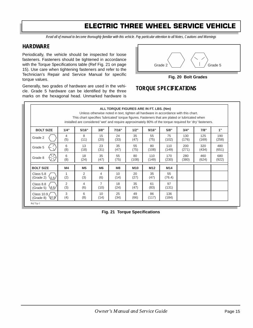
ELECTRIC THREE WHEEL SERVICE VEHICLERead all of manual to become thoroughly familiar with this vehicle. Pay particular attention to all Notes, Cautions and Warnings
HARDWAREPeriodically, the vehicle should be inspected for loosefasteners. Fasteners should be tightened in accordancewith the Torque Specifications table (Ref Fig. 21 on page15). Use care when tightening fasteners and refer to theTechnician’s Repair and Service Manual for specifictorque values.
Generally, two grades of hardware are used in the vehi-cle. Grade 5 hardware can be identified by the threemarks on the hexagonal head. Unmarked hardware is
TORQUE SPECIFICATIONS
Fig. 20 Bolt Grades
Grade 2 Grade 5
Fig. 21 Torque Specifications
ALL TORQUE FIGURES ARE IN FT. LBS. (Nm)
BOLT SIZE
Grade 2
1/4" 5/16" 3/8" 7/16" 1/2" 9/16" 5/8" 3/4" 7/8" 1"
Unless otherwise noted in text, tighten all hardware in accordance with this chart.This chart specifies 'lubricated' torque figures. Fasteners that are plated or lubricated when
installed are considered 'wet' and require approximately 80% of the torque required for 'dry' fasteners.
4(5)
8(11)
15(20)
24(33)
35(47)
55(75)
75(102)
130(176)
125(169)
190(258)
Grade 5
Grade 8
6(8)
13(18)
23(31)
35(47)
55(75)
80(108)
110(149)
200(271)
320(434)
480(651)
6(8)
18(24)
35(47)
55(75)
80(108)
110(149)
170(230)
280(380)
460(624)
680(922)
BOLT SIZE
Class 5.8(Grade 2)
M4 M5 M6 M8 M10 M12 M14
1(2)
2(3)
4(6)
10(14)
20(27)
35(47)
55(76.4)
Class 8.8(Grade 5)
2(3)
4(6)
7(10)
18(24)
35(47)
61(83)
97(131)
Class 10.9(Grade 8)
3(4)
6(8)
10(14)
25(34)
49(66)
86(117)
136(184)
5.8
8.8
10.9
Ref Tsp 1
Page 15Owner’s Manual and Service Guide

ELECTRIC THREE WHEEL SERVICE VEHICLERead all of manual to become thoroughly familiar with this vehicle. Pay particular attention to all Notes, Cautions and Warnings
PERIODIC SERVICE SCHEDULE
✓ Check ♦ Clean, Adjust, etc. ▲ Replace
NOTE: Some maintenance items must be serviced more frequently on vehicles used under severe driving conditions
DAILY
BODY ♦ Clean body components as required
REVERSE WARNING DEVICE ✓ Check operation when direction selector is in reverse
TIRES ✓ Examine for cuts, excessive wear and pressure(See GENERAL SPECIFICATIONS)
WHEELS ✓ Check for bent rims, missing or loose lug nuts
BATTERIES ♦ Recharge to full state of charge after each day’s use
MONTHLY - 20 HOURS (includes items listed in previous table & the following)
BATTERIES♦ Clean batteries & terminals with 1/4 cup (60 ml) baking soda to 1 1/2 gallons (6 liters)
water solution, rinse with clear water
✓ Check charge condition and all connections
SERVICE/ PARK BRAKE✓ Check brake performance, smooth operation
♦ Adjust if required
WIRING ✓ Check all wiring for loose connections and broken/missing insulation
ACCELERATOR ✓ Check for smooth movement
STEERING ✓ Check for excessive play, tightness of all hardware and bent or loose components
REAR AXLE ✓ Check for oil leakage, add lubricant (SAE 80-90 oil) as required 10 Oz (.3L) Capacity.
QUARTERLY - 50 HOURS (includes items listed in previous tables & the following)
FRONT FORK ✓ Check for damage to axle and loose or missing hardware
FRONT WHEEL ALIGNMENT ✓ Check for unusual tire wear, align if required
SERVICE / PARK BRAKE✓ Check for bent/binding linkage rods
✓ Check for damage or wear
Fig. 22 Periodic Service Schedule
Page 16 Owner’s Manual and Service Guide

ELECTRIC THREE WHEEL SERVICE VEHICLERead all of manual to become thoroughly familiar with this vehicle. Pay particular attention to all Notes, Cautions and Warnings
Notes:SEMI-ANNUAL - 125 HOURS (includes items listed in previous tables & the following)
SERVICE / PARK BRAKES♦ Clean and adjust, see Technician’s Repair and Service Manual
✓ Check brake shoe linings, see Technician’s Repair and Service Manual
BODY ♦ Clean body components and wax all painted surfaces
STEERING ♦ Lubricate, use wheel bearing grease
ANNUAL - 250-300 HOURS (includes items listed in previous tables & the following)
FRONT WHEEL BEARINGS♦ Adjust, see Technician’s Repair and Service Manual
♦ Pack, use lithium based wheel bearing grease
REAR AXLE✓ Check lubricant, add lubricant (SAE 80-90 oil) as required
▲ Replace lubricant after 5 years
Fig. 22 Periodic Service Schedule
Page 17Owner’s Manual and Service Guide

ELECTRIC THREE WHEEL SERVICE VEHICLERead all of manual to become thoroughly familiar with this vehicle. Pay particular attention to all Notes, Cautions and Warnings
BATTERIES AND CHARGINGSafety
Always observe the following warnings whenworking on or near batteries:
To prevent burns or bat-tery explosion that couldresult in severe personal
injury or death, keep all smoking materials, openflame or sparks away from the batteries.
Hydrogen gas is formed when charging batteries.Do not charge batteries without adequate ventila-tion. A 4% concentration of hydrogen gas isexplosive.Be sure that the key switch is off and all electricalaccessories are turned off before starting work onvehicle.Never disconnect a circuit under load at a batteryterminal.
Batteries are heavy. Use proper lift-ing techniques when moving them.Always lift the battery with a com-mercially available battery liftingdevice. Use care not to tip batterieswhen removing or installing them;spilled electrolyte can cause burnsand damage.
The electrolyte in a storage battery is an acidsolution which can cause severe burns to the skinand eyes. Treat all electrolyte spills to the bodyand eyes with extended flushing with clear water.Contact a physician immediately.
Always wear a safety shield or approvedsafety goggles when adding water or charg-ing batteries.
Any electrolyte spills should be neutralized with asolution of 1/4 cup (60 ml) sodium bicarbonate(baking soda) dissolved in 1 1/2 gallons (6 liters)of water and flushed with water.Overfilling batteries may result in electrolytebeing expelled from the battery during the chargecycle. Expelled electrolyte may cause personalinjury and damage to the vehicle and storagefacility.
Wrap wrenches wi thvinyl tape to prevent thepossibility of a droppedwrench from ‘shorting
out’ a battery, which could result in an explosionand severe personal injury or death.Aerosol containers of battery terminal protectantmust be used with extreme care. Insulate metalcontainer to prevent can from contacting batteryterminals which could result in an explosion.
BATTERYA battery is defined as two dissimilar metals immersed inan acid. If the acid is absent or if the metals are not dis-similar, a battery has not been created. The batteriesmost commonly used in these vehicles are lead acid.
A battery does not store electricity, but is able to produceelectricity as the result of a chemical reaction whichreleases stored chemical energy in the form of electricalenergy. The chemical reaction takes place faster in warmconditions and slower in cold conditions. Temperature isimportant when conducting tests on a battery and testresults must be corrected to compensate for temperaturedifferences.
As a battery ages, it still performs adequately except thatits capacity is diminished. Capacity describes the timethat a battery can continue to provide its design amperesfrom a full charge.
A battery has a maximum life, therefore good mainte-nance is designed to maximize the available life andreduce the factors that can reduce the life of the battery.
BATTERY MAINTENANCETool List Qty. Required
Insulated wrench, 9/16" ...............................................1Battery carrier ..............................................................1Hydrometer P/N 50900-G1..........................................1Battery maintenance kit P/N 25587-G01 .....................1
At Each Charging Cycle
! !
Page 18 Owner’s Manual and Service Guide
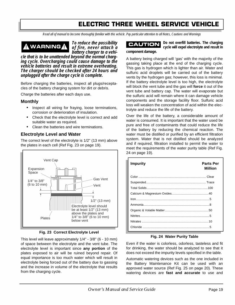
ELECTRIC THREE WHEEL SERVICE VEHICLERead all of manual to become thoroughly familiar with this vehicle. Pay particular attention to all Notes, Cautions and Warnings
To reduce the possibilityof fire, never attach abattery charger to a vehi-
cle that is to be unattended beyond the normal charg-ing cycle. Overcharging could cause damage to thevehicle batteries and result in extreme overheating.The charger should be checked after 24 hours andunplugged after the charge cycle is complete.
Before charging the batteries, inspect all plugs/recepta-cles of the battery charging system for dirt or debris.
Charge the batteries after each days use.
Monthly• Inspect all wiring for fraying, loose terminations,
corrosion or deterioration of insulation.• Check that the electrolyte level is correct and add
suitable water as required.• Clean the batteries and wire terminations.
Electrolyte Level and WaterThe correct level of the electrolyte is 1/2" (13 mm) abovethe plates in each cell (Ref Fig. 23 on page 19).
This level will leave approximately 1/4" - 3/8" (6 - 10 mm)of space between the electrolyte and the vent tube. Theelectrolyte level is important since any portion of theplates exposed to air will be ruined beyond repair. Ofequal importance is too much water which will result inelectrolyte being forced out of the battery due to gassingand the increase in volume of the electrolyte that resultsfrom the charging cycle.
Do not overfill batteries. The chargingcycle will expel electrolyte and result in
component damage.
A battery being charged will ‘gas’ with the majority of thegassing taking place at the end of the charging cycle.This gas is hydrogen which is lighter than air. Water andsulfuric acid droplets will be carried out of the batteryvents by the hydrogen gas; however, this loss is minimal.If the battery electrolyte level is too high, the electrolytewill block the vent tube and the gas will force it out of thevent tube and battery cap. The water will evaporate butthe sulfuric acid will remain where it can damage vehiclecomponents and the storage facility floor. Sulfuric acidloss will weaken the concentration of acid within the elec-trolyte and reduce the life of the battery.
Over the life of the battery, a considerable amount ofwater is consumed. It is important that the water used bepure and free of contaminants that could reduce the lifeof the battery by reducing the chemical reaction. Thewater must be distilled or purified by an efficient filtrationsystem. Water that is not distilled should be analyzedand if required, filtration installed to permit the water tomeet the requirements of the water purity table (Ref Fig.24 on page 19).
Even if the water is colorless, odorless, tasteless and fitfor drinking, the water should be analyzed to see that itdoes not exceed the impurity levels specified in the table.
Automatic watering devices such as the one included inthe Battery Maintenance Kit can be used with anapproved water source (Ref Fig. 25 on page 20). Thesewatering devices are fast and accurate to use and
Fig. 23 Correct Electrolyte Level
! !
Vent Cap
1/4" to 3/8"(6 to 10 mm)
Plates
1/2" (13 mm)
Vent
Gas Vent
ExpansionSpace
Electrolyte level shouldbe at least 1/2" (13 mm)above the plates and1/4" to 3/8" (6 to 10 mm)below vent
Impurity Parts Per Million
Color ............................................................................... Clear
Suspended...................................................................... Trace
Total Solids .......................................................................100
Calcium & Magnesium Oxides...........................................40
Iron......................................................................................5
Ammonia.............................................................................8
Organic & Volatile Matter...................................................50
Nitrites.................................................................................5
Nitrates ..............................................................................10
Chloride ..............................................................................5
Fig. 24 Water Purity Table
Page 19Owner’s Manual and Service Guide
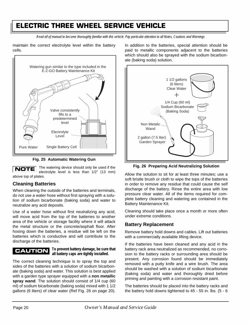
ELECTRIC THREE WHEEL SERVICE VEHICLERead all of manual to become thoroughly familiar with this vehicle. Pay particular attention to all Notes, Cautions and Warnings
maintain the correct electrolyte level within the batterycells.
The watering device should only be used if theelectrolyte level is less than 1/2" (13 mm)
above top of plates.
Cleaning BatteriesWhen cleaning the outside of the batteries and terminals,do not use a water hose without first spraying with a solu-tion of sodium bicarbonate (baking soda) and water toneutralize any acid deposits.
Use of a water hose without first neutralizing any acid,will move acid from the top of the batteries to anotherarea of the vehicle or storage facility where it will attackthe metal structure or the concrete/asphalt floor. Afterhosing down the batteries, a residue will be left on thebatteries which is conductive and will contribute to thedischarge of the batteries.
To prevent battery damage, be sure thatall battery caps are tightly installed.
The correct cleaning technique is to spray the top andsides of the batteries with a solution of sodium bicarbon-ate (baking soda) and water. This solution is best appliedwith a garden type sprayer equipped with a non metallicspray wand. The solution should consist of 1/4 cup (60ml) of sodium bicarbonate (baking soda) mixed with 1 1/2gallons (6 liters) of clear water (Ref Fig. 26 on page 20).
In addition to the batteries, special attention should bepaid to metallic components adjacent to the batterieswhich should also be sprayed with the sodium bicarbon-ate (baking soda) solution.
Allow the solution to sit for at least three minutes; use asoft bristle brush or cloth to wipe the tops of the batteriesin order to remove any residue that could cause the selfdischarge of the battery. Rinse the entire area with lowpressure clear water. All of the items required for com-plete battery cleaning and watering are contained in theBattery Maintenance Kit.
Cleaning should take place once a month or more oftenunder extreme conditions.
Battery ReplacementRemove battery hold downs and cables. Lift out batterieswith a commercially available lifting device.
If the batteries have been cleaned and any acid in thebattery rack area neutralized as recommended, no corro-sion to the battery racks or surrounding area should bepresent. Any corrosion found should be immediatelyremoved with a putty knife and a wire brush. The areashould be washed with a solution of sodium bicarbonate(baking soda) and water and thoroughly dried beforepriming and painting with a corrosion resistant paint.
The batteries should be placed into the battery racks andthe battery hold downs tightened to 45 - 55 in. lbs. (5 - 6
Fig. 25 Automatic Watering Gun
Watering gun similar to the type included in the E-Z-GO Battery Maintenance Kit
Pure Water
Valve consistentlyfills to a
predeterminedlevel
ElectrolyteLevel
Single Battery Cell
Fig. 26 Preparing Acid Neutralizing Solution
1 1/2 gallons(6 liters)
Clear Water
1/4 Cup (60 ml)Sodium Bicarbonate
(Baking Soda)
Non MetalicWand
2 gallon (7.5 liter) Garden Sprayer
Page 20 Owner’s Manual and Service Guide

ELECTRIC THREE WHEEL SERVICE VEHICLERead all of manual to become thoroughly familiar with this vehicle. Pay particular attention to all Notes, Cautions and Warnings
Nm) torque, to prevent movement but not tight enough tocause distortion of the battery cases.
Inspect all wires and terminals. Clean any corrosion fromthe battery terminals or the wire terminals with a solutionof sodium bicarbonate (baking soda) and brush clean ifrequired.
To prevent battery explo-sion that could result insevere personal injury or
death, extreme care must be used with aerosol con-tainers of battery terminal protectant. Insulate themetal container to prevent the metal can from con-tacting battery terminals which could result in anexplosion.
Use care to connect the battery wires as shown (Ref. Fig.27 on page 21) . Tighten the battery post hardware to 50- 70 in. lbs. (6 - 8 Nm) torque. Protect the battery termi-nals and battery wire terminals with a commercially avail-able protective coating.
Prolonged Storage
Battery charger and controller must bedisconnected since they will contribute
to the premature discharge of batteries. Other electronic devicesmay need to be disconnected.
During periods of storage, the batteries will need atten-tion to keep them maintained and prevent discharge. In high temperatures the chemical reaction is faster,while low temperatures cause the chemical reaction toslow down. A vehicle that is stored at 90° F (32° C) willlose .002 of specific gravity each day. If a fully chargedbattery has a specific gravity of 1.275, and the battery is
allowed to sit unused, it will become partially discharged.When it reaches 1.240, which it will do in less thantwenty days, it should be recharged. If a battery is left ina discharged state, sulfating takes place on and withinthe plates. This condition is not reversible and will causepermanent damage to the battery. In order to preventdamage, the battery should be recharged. A hydrometercan be used to determine the specific gravity and there-fore the state of charge of a battery.
In winter conditions, the battery must be fully charged toprevent the possibility of freezing (Ref Fig. 28 on page21). A fully charged battery will not freeze in tempera-tures above -75° F (-60° C). Although the chemical reac-tion is slowed in cold temperatures, the battery must bestored fully charged, and disconnected from any circuitthat could discharge the battery. For portable chargers,disconnect the charging plug from the vehicle receptacle.For on-board chargers, disconnect the charging harnessfrom the batteries. The batteries must be cleaned and alldeposits neutralized and removed from the battery caseto prevent self discharge. The batteries should be testedor recharged at thirty day minimum intervals.
Battery Charging
The battery charger is designed to fully charge the bat-tery set. If the batteries are severely deep cycled, some
Fig. 27 Battery Connections
! !
BL- toESC
BL+ toSolenoid
-
+
-
+
-
+
-
+
RED to Fuse inside Console
BLK toCharger
WHT toCharger
Front of Vehicle
Fig. 28 Freezing Point of Electrolyte
1.1001.120 1.160 1.200 1.240 1.280
1.140 1.180 1.220 1.260 1.300
-9
-15
-21
-26
-32
-37
-43
-48
-54
-60
-65
-71
ELECTROLYTE
TEMPERATURE
SPECIFIC GRAVITY ELECTROLYTE FREEZING POINT
OC
+15
+5
-5
-15
-25
-35
-45
-55
-65
-75
-85
-95
OF
Page 21Owner’s Manual and Service Guide

ELECTRIC THREE WHEEL SERVICE VEHICLERead all of manual to become thoroughly familiar with this vehicle. Pay particular attention to all Notes, Cautions and Warnings
automatic battery chargers contain an electronic modulethat may not activate and the battery charger will notfunction. Automatic chargers will determine the correctduration of charge to the battery set and will shut offwhen the battery set is fully charged. Always refer to theinstructions of the specific charger used.
Before charging, the following should be observed:
Do not overfill batteries. The chargingcycle will expel electrolyte and result in
component damage.
• The electrolyte level in all cells must be at the rec-ommended level and cover the plates.
• The charging must take place in an area that iswell ventilated and capable of removing the hydro-gen gas that is generated by the charging pro-cess. A minimum of five air exchanges per houris recommended.
• The charging connector components are in goodcondition and free from dirt or debris.
• The charger connector is fully inserted into thevehicle receptacle.
• The charger connector/cord set is protected fromdamage and is located in an area to prevent injurythat may result from personnel running over ortripping over the cord set.
• The charger is automatically turned off during theconnect/disconnect cycle and therefore no electri-cal arc is generated at the DC plug/receptaclecontacts.
AC VoltageBattery charger output is directly related to the input volt-age. If multiple vehicles are receiving an incompletecharge in a normally adequate time period, low AC volt-age could be the cause and the power company shouldbe consulted.
TROUBLESHOOTINGIn general, troubleshooting will be done for two distinctreasons. First, a battery that performs poorly and is out-side of the manufacturers specification should be identi-fied in order to replace it under the terms of themanufacturer’s warranty. Different manufacturers havedifferent requirements. Consult the battery manufactureror a service representative for specific requirements.
The second reason is to determine why a particular vehi-cle does not perform adequately. Performance problems
may result in a vehicle that runs slowly or in a vehicle thatis unable to operate for the time required.
A new battery must mature before it will develop its max-imum capacity. Maturing may take up to 100 charge/dis-charge cycles. After the maturing phase, the older abattery gets, the lower the capacity. The only way todetermine the capacity of a battery is to perform a loadtest using a discharge machine following manufacturer’srecommendations.
A cost effective way to identify a poorly performing bat-tery is to use a hydrometer to identify a battery in a setwith a lower than normal specific gravity. Once the partic-ular cell or cells that are the problem are identified, thesuspect battery can be removed and replaced. At thispoint there is nothing that can be done to salvage thebattery; however, the individual battery should bereplaced with a good battery of the same brand, type andapproximate age.
HydrometerA hydrometer (P/N 50900-G1) is used to test the state ofcharge of a battery cell (Ref Fig. 29 on page 23). This isperformed by measuring the density of the electrolyte,which is accomplished by measuring the specific gravityof the electrolyte. The greater the concentration of sulfu-ric acid, the more dense the electrolyte becomes. Thehigher the density, the higher the state of charge.
To prevent battery explo-sion that could result insevere personal injury or
death, never insert a metal thermometer into a bat-tery. Use a hydrometer with a built in thermometerthat is designed for testing batteries.
Specific gravity is the measurement of a liquid that iscompared to a baseline. The baseline is water which isassigned a base number of 1.000. The concentration ofsulfuric acid to water in a new golf car battery is 1.280which means that the electrolyte weighs 1.280 times theweight of the same volume of water. A fully charged bat-tery will test at 1.275 - 1.280 while a discharged batterywill read in the 1.140 range.
Do not perform a hydrometer test on a batterythat has just been watered. The battery must
go through at least one charge and discharge cycle in order topermit the water to adequately mix with the electrolyte.
The temperature of the electrolyte is important since thehydrometer reading must be corrected to 80° F (27° C).High quality hydrometers are equipped with an internal
! !
Page 22 Owner’s Manual and Service Guide

ELECTRIC THREE WHEEL SERVICE VEHICLERead all of manual to become thoroughly familiar with this vehicle. Pay particular attention to all Notes, Cautions and Warnings
thermometer that will measure the temperature of theelectrolyte and will include a conversion scale to correctthe float reading. It is important to recognize that theelectrolyte temperature is significantly different from theambient temperature if the vehicle has been operated.
Using A Hydrometer1. Draw electrolyte into the hydrometer several times to
permit the thermometer to adjust to the electrolytetemperature and note the reading. Examine the colorof the electrolyte. A brown or gray coloration indicatesa problem with the battery and is a sign that the bat-tery is nearing the end of its life.
2. Draw the minimum quantity of electrolyte into thehydrometer to permit the float to float freely withoutcontacting the top or bottom of the cylinder.
3. Hold the hydrometer in a vertical position at eye leveland note the reading where the electrolyte meets thescale on the float.
4. Add or subtract four points (.004) to the reading forevery 10° F (6° C) the electrolyte temperature isabove or below 80° F (27° C). Adjust the reading to
conform with the electrolyte temperature, e.g., if thereading indicates a specific gravity of 1.250 and theelectrolyte temperature is 90° F (32° C), add fourpoints (.004) to the 1.250 which gives a correctedreading of 1.254. Similarly if the temperature was 70°F (21° C), subtract four points (.004) from the 1.250to give a corrected reading of 1.246 (Ref Fig. 30 onpage 23).
Fig. 29 Hydrometer
32282420161284048
12162024283236
3228242016128404 4 8
1212161620202424282832323636
1100
1125
1150
1200
1225
1250
1275
1300
1100
1125
1150
1200
1225
1250
1275
1300
Add to FloatReading
Subtract from FloatReading
Bulb Cylinder
Float
Weight
Thermometer
1175
Fig. 30 Hydrometer Temperature Correction
160 71 +.032+.030
150 66 +.028+.026
140 60 +.024+.022
130 54 +.020+.018
120 49 +.016+.014
110 43 +.012+.010
100 38 +.008+.006
90 32 +.004+.002
80 27 0–.002
70 21 –.004–.006
60 16 –.008–.010
50 10 –.012–.014
40 4 –.016–.018
30 –1 –.020–.022
2 –7 –.024–.026
10 –12 –.028
EXAMPLE #1:
Electrolyte TemperatureAbove 80˚ F (27˚ C)
Electrolyte temperature90˚ F (32˚ C)Hydrometer reading 1.2501.250 + .004 = 1.254corrected specific gravity
Electrolyte TemperatureBelow 80˚ F (27˚ C)
Electrolyte temperature70˚ F (21˚ C)Hydrometer reading 1.2501.250 - .004 = 1.246corrected specific gravity
EXAMPLE #2:
˚ F ˚ C
ElectrolyteTemperature
Page 23Owner’s Manual and Service Guide
ELECTRIC THREE WHEEL SERVICE VEHICLERead all of manual to become thoroughly familiar with this vehicle. Pay particular attention to all Notes, Cautions and Warnings
5. Test each cell and note the readings (corrected to 80°F or 27° C). A variation of fifty points between any twocell readings (example 1.250 - 1.200) indicates aproblem with the low reading cell(s).
As a battery ages the specific gravity of the electrolytewill decrease at full charge. This is not a reason toreplace the battery, providing all cells are within fiftypoints of each other.
Since the hydrometer test is in response to a vehicleexhibiting a performance problem, the vehicle should berecharged and the test repeated. If the results indicate aweak cell, the battery or batteries should be removedand replaced with a good battery of the same brand, typeand approximate age.
Page 24 Owner’s Manual and Service Guide

ELECTRIC THREE WHEEL SERVICE VEHICLERead all of manual to become thoroughly familiar with this vehicle. Pay particular attention to all Notes, Cautions and Warnings
E-Z-GO FACTORY SET CONTROLLER PARAMETERS
PARAMATER RANGE DEFAULT DESIRED UNITS DESCRIPTION
Current Limit, Main 20 - 250 250 250 Amps Maximum current forward speed
Current Limit, Low SpeedMain 20 - 250 250 250 Amps Maximum current reverse speed
Current Limit, Plug 20 - 250 70 70 Amps Max. plug current forward speed
Current Limit, Low SpeedPlug 20 - 250 70 70 Amps Max. plug current reverse speed
Current Limit, EmergencyReverse 20 - 250 140 250 Amps Max. plug current in emergency
reverse
Current Limit, Low SpeedEmergency Reverse 20 - 250 140 250 Amps Max. plug current in low speed emer-
gency reverse
Current Limit, Ramp Start 20 - 250 140 250 Amps Max. plug current during ramp start
Current Limit, Low SpeedRamp Start 20 - 250 140 250 Amps Max. plug current during ramp start in
low speed
Acceleration Rate 0 - 3 1 0.8 Sec. Time to reach full output from zerooutput
Quick Start 0 - 6 1.4 0.2 Output will respond to rate of throttlechange
Throttle type type 1, 2, 3 type 1 type 2 Ohm orVolts
Type of throttle input type 2 = 0-5V, 3-wire pot
Ramp Shape 20 - 70 50 50 %Adjust desired PWM output at 50%
throttle to vary throttle sensitivity atlow speed
Creep Speed/Min. DutyCycle 0 - 25 10 0 % Speed at min. throttle setting
Low Speed 40 - 100 60 55 % Max. speed in reverse
High Speed 40 - 100 100 100 % Max. speed in forward
Emergence Reverse Speed 25 - 100 100 100 % Speed during emergency reverse
Sequencing Delay 0 - 3 0 0 Sec. Delays HPD and SRO from brakeafter controller is enabled
Variable Plug On/Off On On On = plug current dependent uponthrottle position. Off = fixed
High Pedal Disable (HPD) 0 - 2 0 1 Option to disable controller if throttle
is applied before brake or keyswitchinput (KSI)
Static Return To Off (SRO) type 0, 1, 2 type 1brake
type 0 NoSRO
Sequencing of KSI or brake beforedirection is selected
Anti - tiedown On/Off On Off Prevents high speed mode if HSS innot released after brake
Fig. 31 Factory Settings
Page 25Owner’s Manual and Service Guide

ELECTRIC THREE WHEEL SERVICE VEHICLERead all of manual to become thoroughly familiar with this vehicle. Pay particular attention to all Notes, Cautions and Warnings
Fig. 32 Wiring Diagram
8
P14CONTROLLERP2P12
16 M--
892999
891653
890495
891862
REAR LIGHT(COM)
886649
886649
887855 892458
TL (+) BL (+)
CB
W R
891655
RESISTOR893142
P4
REV
BL
OR
OR
W
B
BRBR R
Y
W/B 4
CHARGER24V 89286036V 893090
STOPLIGHT SWITCH814005 (MINUTE MISER)
STOPLIGHT SWITCH886182 (TUG)
MINUTE MISER 892671TUG 884890
HOUR METER 886802
BL
R
R
W/R
R
W/B
B
B
R
R
W/BL
R
W/G
G
BL
G
BR
R
RW
Y
A--YELLOWB--WHITEC--BLUE
OR
Y
WBL
OR 11Y 7
W 6BL 5
TAILLIGHT892676
CONTROLLER892789
A2B+B--M--P3
P16P11P5
P6P7
REARLIGHT
P2-- REVERSEP3-- FORWARDP4-- MAIN CONTACTP5-- POT HIGHP6-- 0--5V INPUTP7-- POT LOWP11-- REVERSE (INPUT)P12-- FORWARD (INPUT)P14-- HIGH (INPUT)P16-- KEYSWITCH (INPUT)
FWD
24V 84120836V 841112
R
RPOT AY892894
W
CA
UT
ION
1 9
W/BL 2W/G 3
G 12BR 14
W/B
R
W
G
BR
R
W/BLW/G
B
R
A2
B--
B+
BR
Y
B
W
R
ALL WIRES IN MAIN HARNESS SEAT SWITCH AY158135--01
WIRE COLOR CHARTB BLACKBL BLUEBR BROWNG GREEN
OR ORANGEPK PINKR REDW WHITE
W/B WHITE/BLACKW/BL WHITE/BLUEW/BR WHITE/BROWNW/R WHITE/REDW/Y WHITE/YELLOW
Y YELLOWW/G WHITE/GREEN
R
B
G
A1
S1
A2
S2
MAINCONTACT
24V84124836V841123
24V84124836V841123
B
RBGORBR
RR
B
W
Y
887855
W/R
R
R
DIODE884398
897160 UNLESS NOTED.
W/Y
W/Y
892901
Y
Y
84076616--CONNECT OR
840765TERMINAL
W/Y 16R 15
Page 26 Owner’s Manual and Service Guide

ELECTRIC THREE WHEEL SERVICE VEHICLERead all of manual to become thoroughly familiar with this vehicle. Pay particular attention to all Notes, Cautions and Warnings
Fig. 33 Wiring Diagram
MEMORYMODULE841852
BR
S1
BRR
OR G
OPTIONALQUICK
DISCONNECT
AC RELAY
883078
CHARGER
HORN BUTTON
KEY
SEAT SW
YY
Y
HORN886090
OR
EC TUG MM
TUG LIFTOUT RACK
BROR
OR
CONNECTION FOR WIRINGHORN WITH TUG STEERINGWHEEL MOD.
OR
FO
RW
AR
D
RE
VE
RS
E
891693
891657
EC TUG MM
884045
887204
TUG LIFTOUT RACK
893383893282
TOCIRCUITBRKR
24V MINUTEMISER
FRONT
6V
6V 6V
6V
B
36V TUG
B
FOOTSWITCH
W/B
BRIDGERECTIFIER840679
B
RB
W/BW/B
BR
CIRCUIT BRKR: MINUTE MISER 829164TUG 824800
R
R
BR
B B
BBL
6V
MINUTE MISERBRAKE LIGHT SW
6V
MAIN CONTACT
0R
2 4 1
CCW
0V
5V
DIRECTIONSWITCH
TUG BRAKELIGHT SW
HEADLIGHTSWITCH
A2S2
A1
+
ACAC
B-- B+
FORWARD
REVERSE
REVERSEWARNINGBUZZER890000
BATTERIES
Y W/BL
W/BL
W/BL
W/B
W/B
Y G
YBR
BR
W
B
B
W/BL
Y
YR
B R
20 AMPCIRCUIT BREAKER829780
BR
KEY SWITCH886311
892523HEADLIGHT
AC
CIG
N
BA
TT
B
BL
6V
6V
HEADLIGHTSWITCH
830640HORN BUTTON
806791
FRONT
R
6V
6V
DIRECTIONSWITCH836354
BATTERYCONDITIONMETER:24V 84052636V 841111
HEADLIGHT
HORN
BCI
HOURMETER
REVALARM
RR
B
W
Y
0RBR
GBR
B
2 4 1
W/BLB RB
3
RB
NOT USED ON STD.BAT. COND. METER
WIRE DESTINATIONSSAME AS STD. METER
36V BAT. COND.METER 841851
LIFTOUT BATTERYRACK APPLICATION(24V MINUTE MISER
BATTERY ARRANGEMENTSHOWN IN SCHEMATIC)
892833
Y
Y
Page 27Owner’s Manual and Service Guide
ELECTRIC THREE WHEEL SERVICE VEHICLERead all of manual to become thoroughly familiar with this vehicle. Pay particular attention to all Notes, Cautions and Warnings
Notes:
Page 28 Owner’s Manual and Service Guide

Page 29
GENERAL SPECIFICATIONS
Owner’s Manual and Service Guide
GENERAL SPECIFICATIONS

GENERAL SPECIFICATIONS
ELECTRIC POWERED THREE WHEEL SERVICE VEHICLEBATTERY MONITORING.................................................. LED State of charge meterBATTERIES....................................................................... Four 6 volt deep cycle (105 minute minimum, 225 amp-hour @ 20 hour discharge
rate)SPEED CONTROLLER..................................................... Programmable Solid state, 250 amp capacityMOTOR ............................................................................. 24 VDC, series wound 1.5 hp (1.1 kW) @ 2800 rpm & 4.3 hp (3.2 kW) @ 1200
rpm, brazed armature and solid copper windingsREAR AXLE ...................................................................... Bevel gear with spur and helical gearreduction with input pinion shaft directly
connected to motor shaftBRAKES............................................................................ Dual rear wheel, self adjusting mechanical drum brakesPARKING BRAKE ............................................................. Toe lock combined with service brakeFRONT SUSPENSION ..................................................... Rubber mounted torque armREAR SUSPENSION........................................................ Coil springs and hydraulic shock absorberSTEERING ........................................................................ Handlebar connected directly to front forkSEATING........................................................................... Driver and rear facing passengerTOTAL LOAD CAPACITY.................................................. 550 lbs. (250 kg) including operator, accessories & cargoSPEED .............................................................................. 10 1/2 mph (17 kph)CHASSIS........................................................................... Welded tubular steel; powder coated (Durashield™)VEHICLE PROTECTION .................................................. NoneBODY ................................................................................ Diamond pattern body with Durashield™ Industrial Yellow powder coat paintSTANDARD COLOR ......................................................... Industrial YellowLOAD BED ........................................................................ 22 3/4" (58cm) x 28 1/2" (72cms) x 4" (10cms)LOAD BED FEATURES .................................................... Removable panel for powertrain accessLIGHTING (Standard)........................................................ Rear brake lightTIRES (Standard) .............................................................. 4.80 x 8 Industrial Load Range BTIRE PRESSURE ............................................................. 60 psi (415 kPa)WEIGHT (with batteries) ................................................... 690 lbs. (315 kg)OPERATING CONTROLS & INSTRUMENTATION .......... Removable key, ‘deadman’ accelerator control, direction selector, audible reverse
warningBATTERY CHARGER ....................................................... Lestronic II built-in 24 V, 120 VAC, fully automatic, line compensating, 25 amp DC
output at 24 volts, 60 Hz, UL recognized, CSA certifiedRANGE (Nominal) ............................................................. 35 miles (56kms) max
Specifications subject to change without notice
Page 30 Owner’s Manual and Service Guide

GENERAL SPECIFICATIONS
Fig. 33 Vehicle Dimensions and Incline Specifications
RECOMMENDED MAXIMUM RAMP GRADE25% or 14˚ MAXIMUM
RECOMMENDED MAXIMUM SIDE TILT25% or 14˚ MAXIMUM
22.75 in(58 cm)
28.5 in(73 cm)
30 in(76 cm)
25.8 in(65 cm)
4 in(10 cm)
39 in(99 cm)
53 in(135 cm)
85 in (216 cm)
Page 31Owner’s Manual and Service Guide

GENERAL SPECIFICATIONS
Fig. 34 Vehicle Turning Clearance Diameter and Intersecting Aisle Clearance
TURNING CLEARANCEDIAMETER
54 in.(137 cm)
54 in(137 cm)
INTERSECTINGAISLE CLEARANCE
130 in (330 cm) (Handlebar)154 in (391 cm)
Page 32 Owner’s Manual and Service Guide

Read and understand the following warningsbefore attempting to operate the vehicle:
To prevent personalinjury or death, observethe following:
When vehicle is to be left unattended, release ped-al completely, move direction selector to neutral,turn key to ‘OFF’ position and remove key.Drive vehicle only as fast as terrain and safetyconsiderations allow. Consider the terrain andtraffic conditions. Consider environmental factorswhich effect the terrain and the ability to controlthe vehicle.Avoid driving fast down hill. Sudden stops orchange of direction may result in a loss of control.Use service brake to control speed when travelingdown an incline.Use extra care and reduced speed when drivingon poor surfaces, such as loose dirt, wet grass,gravel, etc.All travel should be directly up or down hills.Use extra care when driving the vehicle across anincline.Stay in designated areas and avoid steep slopes.Use the parking brake whenever the vehicle isparked.Keep feet, legs, hands and arms inside vehicle atall times.Avoid extremely rough terrain.Check area behind the vehicle before operating inreverse.Make sure the direction selector is in correct posi-tion before attempting to start the vehicle.Slow down before and during turns. All turnsshould be executed at reduced speed.Always bring vehicle to a complete stop beforeshifting the direction selector.See GENERAL SPECIFICATIONS for standardvehicle load and occupant capacity.
Read and understand the following text andwarnings before attempting to service vehicle:
In any product, components will eventually fail to performproperly as the result of normal use, age, wear or abuse.It is virtually impossible to anticipate all possible compo-nent failures or the manner in which each componentmay fail.Be aware that a vehicle requiring repair indicates that thevehicle is no longer functioning as designed and there-fore should be considered potentially hazardous. Useextreme care when working on any vehicle. When diag-nosing, removing or replacing any components that arenot operating correctly, take time to consider the safety ofyourself and others around you should the componentmove unexpectedly.Some components are heavy, spring loaded, highly cor-rosive, explosive or may produce high amperage orreach high temperatures. Battery acid and hydrogen gascould result in serious bodily injury to the technician/mechanic and bystanders if not treated with the utmostcaution. Be careful not to place hands, face, feet or bodyin a location that could expose them to injury should anunforeseen situation occur.
To prevent personalinjury or death, observethe following:
Before working on the vehicle, remove all jewelry(rings, watch, necklaces, etc.).Be sure no loose clothing or hair can contactmoving parts.Use care not to touch hot objects.Raise entire vehicle and support on jack standsbefore attempting to run or adjust powertrain.Wear eye protection when working on or aroundthe vehicle. In particular, use care when workingaround batteries, using solvents or compressedair.Hydrogen gas is formed when charging batteries.Do not charge batteries without adequate ventila-tion.Do not permit open flame or anyone to smoke inan area that is being used for charging batteries.A concentration of 4% hydrogen gas or more isexplosive.
! !
! !

Copyrighted MaterialThis manual may not be reproduced in whole or
in part without the express permission ofE-Z-GO Division of TEXTRON Inc.
Technical Communications Department
1451 Marvin Griffin Road, Augusta, Georgia USA 30906-3852
TO CONTACT US
North America: Technical Assistance & Warranty Phone: 1-800-774-3946, FAX: 1-800-448-8124 Service Parts Phone: 1-888-GET-EZGO (1-888-438-3946), FAX: 1-800-752-6175
International: Phone: 010-1-706-798-4311, FAX: 010-1-706-771-4609