OWNER’S GUIDE - Link Mfg
14
Link Mfg. Ltd. 223 15th St. N.E. Sioux Center, IA USA 51250-2120 www.linkmfg.com QUESTIONS? CALL CUSTOMER SERVICE 1-800-222-6283 80002291 MAY 31, 2016 OWNER’S GUIDE 8A000726 DURALIFT II 8000 LB. CAPACITY DEALER / INSTALLER: Complete this section and give to vehicle owner. Serial No: ____________________________________________________ Part No: 8A000726 Capacity: 8000 lbs. Date Installed: ________________________________________________ Refer to separate Installation Instructions for installation details. Link Mfg. Ltd. 223 15th St. N.E. Sioux Center, IA USA 51250-2120 www.linkmfg.com QUESTIONS? CALL CUSTOMER SERVICE 1-800-222-6283 80002291 MAY 31, 2016 OWNER’S GUIDE 8A000726 DURALIFT II 8000 LB. CAPACITY DEALER / INSTALLER: Complete this section and give to vehicle owner. Serial No: ____________________________________________________ Part No: 8A000726 Capacity: 8000 lbs. Date Installed: ________________________________________________ Refer to separate Installation Instructions for installation details.
Transcript of OWNER’S GUIDE - Link Mfg

Link Mfg. Ltd. 223 15th St. N.E.
Sioux Center, IA USA 51250-2120
www.linkmfg.com
QUESTIONS? CALL CUSTOMER
SERVICE 1-800-222-6283
80002291 MAY 31, 2016
OWNER’S GUIDE
8A000726 DURALIFT II 8000 LB. CAPACITY
DEALER / INSTALLER: Complete this section and give to vehicle owner.
Serial No: ____________________________________________________ Part No: 8A000726 Capacity: 8000 lbs. Date Installed: ________________________________________________
Refer to separate Installation Instructions for installation details.
Page 2
IMPORTANT: PLEASE READ THIS ENTIRE MANUAL BEFORE OPERATING YOUR SUSPEN-SION AND KEEP IT FOR FUTURE REFERENCE. 1. INTRODUCTION Thank you for choosing a Link Duralift II liftable suspension. We want to help you to get the best results from the suspen-sion and to operate it safely. This manual contains information to introduce you to the Link Duralift II liftable suspension and to assist you with its operation and maintenance. The manual is intended solely for use with this product. All information in this manual is based on the latest information available at the time of printing. Link Manufacturing re-serves the right to change its products or manuals at any time without notice. Contact Link at (800) 222-6283 or visit www.linkmfg.com for information on recent changes to products.
Table of Contents
1. Introduction 2
2. Axle Identification 3
3. Safety Warnings 3
4. Operation 4-5
5. Maintenance 5-6
6. Troubleshooting 6
7. Warranty 7
8. Parts Lists 8-14
Page 3
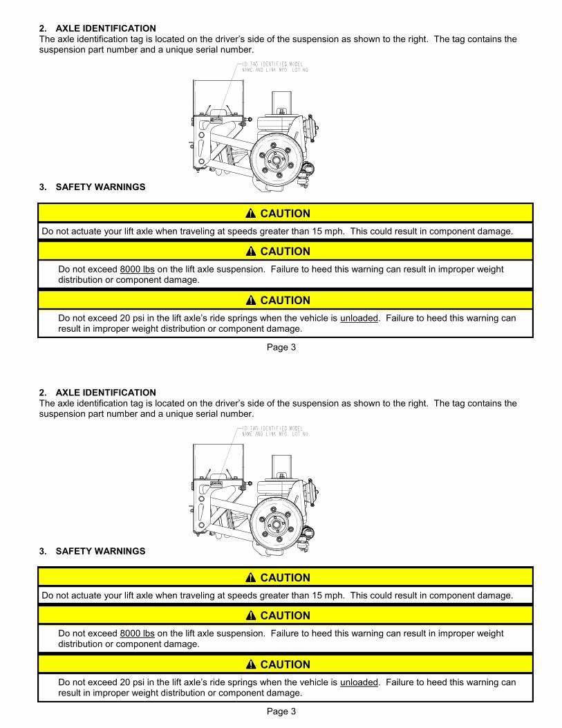
2. AXLE IDENTIFICATION The axle identification tag is located on the driver’s side of the suspension as shown to the right. The tag contains the suspension part number and a unique serial number. 3. SAFETY WARNINGS
CAUTION
Do not exceed 20 psi in the lift axle’s ride springs when the vehicle is unloaded. Failure to heed this warning can result in improper weight distribution or component damage.
CAUTION
Do not exceed 8000 lbs on the lift axle suspension. Failure to heed this warning can result in improper weight distribution or component damage.
CAUTION
Do not actuate your lift axle when traveling at speeds greater than 15 mph. This could result in component damage.
Page 3
2. AXLE IDENTIFICATION The axle identification tag is located on the driver’s side of the suspension as shown to the right. The tag contains the suspension part number and a unique serial number. 3. SAFETY WARNINGS
CAUTION
Do not exceed 20 psi in the lift axle’s ride springs when the vehicle is unloaded. Failure to heed this warning can result in improper weight distribution or component damage.
CAUTION
Do not exceed 8000 lbs on the lift axle suspension. Failure to heed this warning can result in improper weight distribution or component damage.
CAUTION
Do not actuate your lift axle when traveling at speeds greater than 15 mph. This could result in component damage.

Page 4
8K AIR PRESSURE AXLE LOAD CHART (For reference only. Use scale to determine actual loads.)
LOAD IN LBS AT GROUND DURALIFT II PSI
4000 28
5000 37
6000 46
7000 55
8000 64
CAUTION
Do not actuate your lift axle when traveling at speeds greater than 15 mph. This could result in component damage.
CAUTION
Do not exceed 8000 lbs on the lift axle suspension. Failure to heed this warning can result in improper weight distribution or component damage.
CAUTION
Do not exceed 20 psi in the lift axle’s ride springs when the vehicle is unloaded. Failure to heed this warning can result in improper weight distribution or component damage.
4. OPERATION 4.1 Lowering Your Lift Axle
4.1.1 To lower the axle, move the toggle switch to the “Lower” position. 4.1.2 Use the regulator to adjust the air pressure as on the gauge to the appropriate air pressure for the vehicle load conditions. Refer to chart below for recommended pressures.

Page 5
5. MAINTENANCE
After first month or 1,000 miles
❑ Check for loose suspension fasteners (Tighten to values given on Torque Table on following page).
Every month or 1,000 miles
❑ Check wheel bearing oil level and inspect wheels for leaks (SAE 80W-90 Mineral Based Gear Lube). ❑ Check suspension for debris rubbing air springs. ❑ Check for worn steering stabilizer shocks.
Every three months or 2,500 miles
❑ Grease camshaft bushings (Multipurpose NLGI 2). ❑ Check for worn suspension bushings. ❑ Check for loose suspension fasteners (Tighten to values given on Torque Table on following page). ❑ Check brake lining wear and replace any cracked, broken or oil soaked linings. ❑ Inspect brake drums for heat checks, grooves, hot spots, glazing, cracks and out of round and replace if necessary. ❑ Inspect wheel ends for excessive play.
Every twelve months or 10,000 miles
❑ Grease slack adjusters (Multipurpose NLGI 2). ❑ Replace wheel bearings lubricating oil (SAE 80W-90 Mineral Based or SAE 75W-80 Synthetic Gear Lube). ❑ Check brake chambers and slack adjusters for proper function and excessive wear. ❑ Inspect brake rollers, roller shafts, anchor pins and bushings for excessive wear and replace if necessary. ❑ Check shoes for bent shoe ribs, cracks in shoe table welds and elongated rivet holes and replace if necessary. ❑ Inspect suspension air controls for proper function and leaks.
4. OPERATION (continued) 4.2 Raising Your Lift Axle
4.2.1 To raise the axle, move the toggle switch to the “Raise” position.
CAUTION
Do not actuate your lift axle when traveling at speeds greater than 15 mph. This could result in component damage.
Page 6
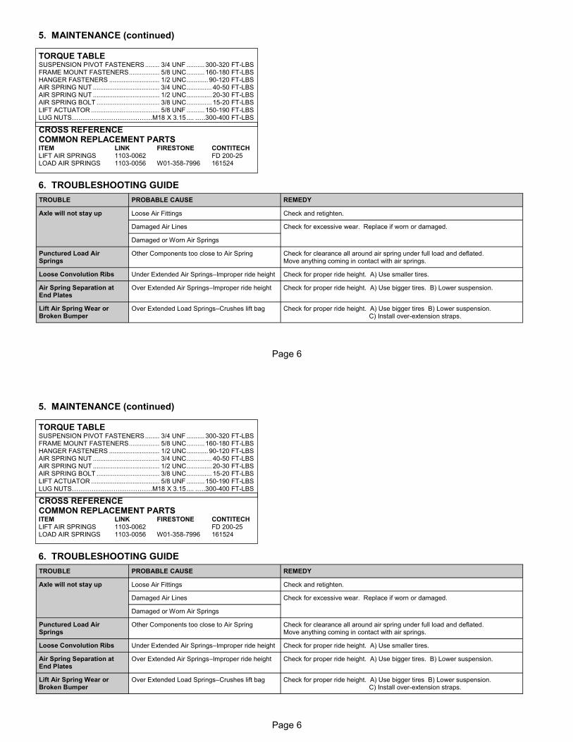
TORQUE TABLE SUSPENSION PIVOT FASTENERS ........ 3/4 UNF .......... 300-320 FT-LBS FRAME MOUNT FASTENERS ................. 5/8 UNC .......... 160-180 FT-LBS HANGER FASTENERS ............................ 1/2 UNC ............ 90-120 FT-LBS AIR SPRING NUT ..................................... 3/4 UNC .............. 40-50 FT-LBS AIR SPRING NUT ..................................... 1/2 UNC .............. 20-30 FT-LBS AIR SPRING BOLT ................................... 3/8 UNC .............. 15-20 FT-LBS LIFT ACTUATOR ...................................... 5/8 UNF .......... 150-190 FT-LBS LUG NUTS……………………………….M18 X 3.15 .... .….300-400 FT-LBS
6. TROUBLESHOOTING GUIDE
TROUBLE PROBABLE CAUSE REMEDY
Loose Air Fittings Check and retighten. Axle will not stay up
Damaged Air Lines Check for excessive wear. Replace if worn or damaged.
Damaged or Worn Air Springs
Punctured Load Air Springs
Other Components too close to Air Spring Check for clearance all around air spring under full load and deflated. Move anything coming in contact with air springs.
Loose Convolution Ribs Under Extended Air Springs–Improper ride height Check for proper ride height. A) Use smaller tires.
Air Spring Separation at End Plates
Over Extended Air Springs–Improper ride height Check for proper ride height. A) Use bigger tires. B) Lower suspension.
Lift Air Spring Wear or Broken Bumper
Over Extended Load Springs–Crushes lift bag Check for proper ride height. A) Use bigger tires B) Lower suspension. C) Install over-extension straps.
CROSS REFERENCE COMMON REPLACEMENT PARTS ITEM LINK FIRESTONE CONTITECH LIFT AIR SPRINGS 1103-0062 FD 200-25 LOAD AIR SPRINGS 1103-0056 W01-358-7996 161524
5. MAINTENANCE (continued)
Page 6
TORQUE TABLE SUSPENSION PIVOT FASTENERS ........ 3/4 UNF .......... 300-320 FT-LBS FRAME MOUNT FASTENERS ................. 5/8 UNC .......... 160-180 FT-LBS HANGER FASTENERS ............................ 1/2 UNC ............ 90-120 FT-LBS AIR SPRING NUT ..................................... 3/4 UNC .............. 40-50 FT-LBS AIR SPRING NUT ..................................... 1/2 UNC .............. 20-30 FT-LBS AIR SPRING BOLT ................................... 3/8 UNC .............. 15-20 FT-LBS LIFT ACTUATOR ...................................... 5/8 UNF .......... 150-190 FT-LBS LUG NUTS……………………………….M18 X 3.15 .... .….300-400 FT-LBS
6. TROUBLESHOOTING GUIDE
TROUBLE PROBABLE CAUSE REMEDY
Loose Air Fittings Check and retighten. Axle will not stay up
Damaged Air Lines Check for excessive wear. Replace if worn or damaged.
Damaged or Worn Air Springs
Punctured Load Air Springs
Other Components too close to Air Spring Check for clearance all around air spring under full load and deflated. Move anything coming in contact with air springs.
Loose Convolution Ribs Under Extended Air Springs–Improper ride height Check for proper ride height. A) Use smaller tires.
Air Spring Separation at End Plates
Over Extended Air Springs–Improper ride height Check for proper ride height. A) Use bigger tires. B) Lower suspension.
Lift Air Spring Wear or Broken Bumper
Over Extended Load Springs–Crushes lift bag Check for proper ride height. A) Use bigger tires B) Lower suspension. C) Install over-extension straps.
CROSS REFERENCE COMMON REPLACEMENT PARTS ITEM LINK FIRESTONE CONTITECH LIFT AIR SPRINGS 1103-0062 FD 200-25 LOAD AIR SPRINGS 1103-0056 W01-358-7996 161524
5. MAINTENANCE (continued)
Page 7
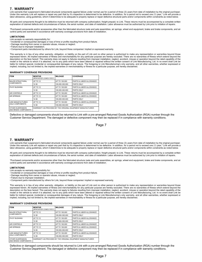
7. WARRANTY Link warrants their suspension’s fabricated structural components against failure under normal use for a period of three (3) years from date of installation by the original purchaser. Under this warranty Link will replace or repair any part that by it’s inspection is determined to be defective. In addition, for a period not to exceed one (1) year,* Link will provide a labor allowance, using guidelines, which it determines to be adequate to properly replace or repair defective structural parts and/or components within constraints as noted below. All parts and components thought to be defective must be returned with company authorization, freight prepaid, to Link. These returns must be accompanied by a complete written explanation of claimed defects and circumstances of failure, the serial number, and date of installation. Labor allowance must be authorized by Link prior to initiation of repairs. *Purchased components and/or accessories other than the fabricated structure (axle and axle assemblies, air springs, wheel end equipment, brake and brake components, and air control parts) are warranted in accordance with warranty coverage provisions from date of installation.
LIMITATIONS Link accepts no warranty responsibility for: • Incidental or consequential damages or loss of time or profits resulting from product failure. • Damage resulting from owner or operator abuse, misuse or neglect. • Failure due to improper installation. • Component parts manufactured by others for Link, beyond those companies’ implied or expressed warranty. This warranty is in lieu of any other warranty, obligation, or liability on the part of Link and no other person is authorized to make any representation or warranties beyond those expressed herein. All implied warranties of fitness and merchantability for any particular purpose are hereby excluded. There are no warranties of fitness which extend beyond the description on the face hereof. This warranty does not apply to failures resulting from improper installation, neglect, accident, misuse or operation beyond the rated capability of the model or the vehicle to which it is attached, nor to any parts which have been altered or repaired without the written consent of Link Manufacturing, Ltd. In no event shall Link be liable for indirect special, incidental or consequential damages of any nature. The foregoing is Link Manufacturing’s only warranty, and all other warranties, whether expressed or implied, including, but not limited to, the implied warranties or merchantability or fitness for a particular purpose, are hereby disclaimed.
WARRANTY COVERAGE PROVISIONS ITEM MONTHS
(WHICHEVER COMES FIRST)
MILEAGE COVERAGE
MAJOR STRUCTURAL COMPONENTS
UP TO 12 UP TO 100,000 PARTS & LABOR ALLOWANCE
12-36 100,000-300,000 PARTS ONLY
PIVOT BUSHING UP TO 12 UP TO 100,000 PARTS & LABOR ALLOWANCE
12-36 100,000-300,000 PARTS ONLY
AIR CONTROLS UP TO 12 UP TO 100,000 PARTS & LABOR ALLOWANCE
AIR SPRINGS UP TO 12 UP TO 100,000 PARTS & LABOR ALLOWANCE
12-36 100,000-300,000 PARTS ONLY
LINK MANUFACTURED AXLE COMPONENTS
UP TO 12 UP TO 100,000 PARTS & LABOR ALLOWANCE
12-36 100,000-300,000 PARTS ONLY
OTHER SUSPENSION AND BRAKE COMPONENTS
WARRANTY AS PROVIDED BY THE ORIGINAL EQUIPMENT MANUFACTURER
Defective or damaged components should be returned to Link with a pre-arranged Returned Goods Authorization (RGA) number through the Customer Service Department. The damaged or defective component may then be replaced if in compliance with warranty conditions.
Page 7
7. WARRANTY Link warrants their suspension’s fabricated structural components against failure under normal use for a period of three (3) years from date of installation by the original purchaser. Under this warranty Link will replace or repair any part that by it’s inspection is determined to be defective. In addition, for a period not to exceed one (1) year,* Link will provide a labor allowance, using guidelines, which it determines to be adequate to properly replace or repair defective structural parts and/or components within constraints as noted below. All parts and components thought to be defective must be returned with company authorization, freight prepaid, to Link. These returns must be accompanied by a complete written explanation of claimed defects and circumstances of failure, the serial number, and date of installation. Labor allowance must be authorized by Link prior to initiation of repairs. *Purchased components and/or accessories other than the fabricated structure (axle and axle assemblies, air springs, wheel end equipment, brake and brake components, and air control parts) are warranted in accordance with warranty coverage provisions from date of installation.
LIMITATIONS Link accepts no warranty responsibility for: • Incidental or consequential damages or loss of time or profits resulting from product failure. • Damage resulting from owner or operator abuse, misuse or neglect. • Failure due to improper installation. • Component parts manufactured by others for Link, beyond those companies’ implied or expressed warranty. This warranty is in lieu of any other warranty, obligation, or liability on the part of Link and no other person is authorized to make any representation or warranties beyond those expressed herein. All implied warranties of fitness and merchantability for any particular purpose are hereby excluded. There are no warranties of fitness which extend beyond the description on the face hereof. This warranty does not apply to failures resulting from improper installation, neglect, accident, misuse or operation beyond the rated capability of the model or the vehicle to which it is attached, nor to any parts which have been altered or repaired without the written consent of Link Manufacturing, Ltd. In no event shall Link be liable for indirect special, incidental or consequential damages of any nature. The foregoing is Link Manufacturing’s only warranty, and all other warranties, whether expressed or implied, including, but not limited to, the implied warranties or merchantability or fitness for a particular purpose, are hereby disclaimed.
WARRANTY COVERAGE PROVISIONS ITEM MONTHS
(WHICHEVER COMES FIRST)
MILEAGE COVERAGE
MAJOR STRUCTURAL COMPONENTS
UP TO 12 UP TO 100,000 PARTS & LABOR ALLOWANCE
12-36 100,000-300,000 PARTS ONLY
PIVOT BUSHING UP TO 12 UP TO 100,000 PARTS & LABOR ALLOWANCE
12-36 100,000-300,000 PARTS ONLY
AIR CONTROLS UP TO 12 UP TO 100,000 PARTS & LABOR ALLOWANCE
AIR SPRINGS UP TO 12 UP TO 100,000 PARTS & LABOR ALLOWANCE
12-36 100,000-300,000 PARTS ONLY
LINK MANUFACTURED AXLE COMPONENTS
UP TO 12 UP TO 100,000 PARTS & LABOR ALLOWANCE
12-36 100,000-300,000 PARTS ONLY
OTHER SUSPENSION AND BRAKE COMPONENTS
WARRANTY AS PROVIDED BY THE ORIGINAL EQUIPMENT MANUFACTURER
Defective or damaged components should be returned to Link with a pre-arranged Returned Goods Authorization (RGA) number through the Customer Service Department. The damaged or defective component may then be replaced if in compliance with warranty conditions.
Page 8
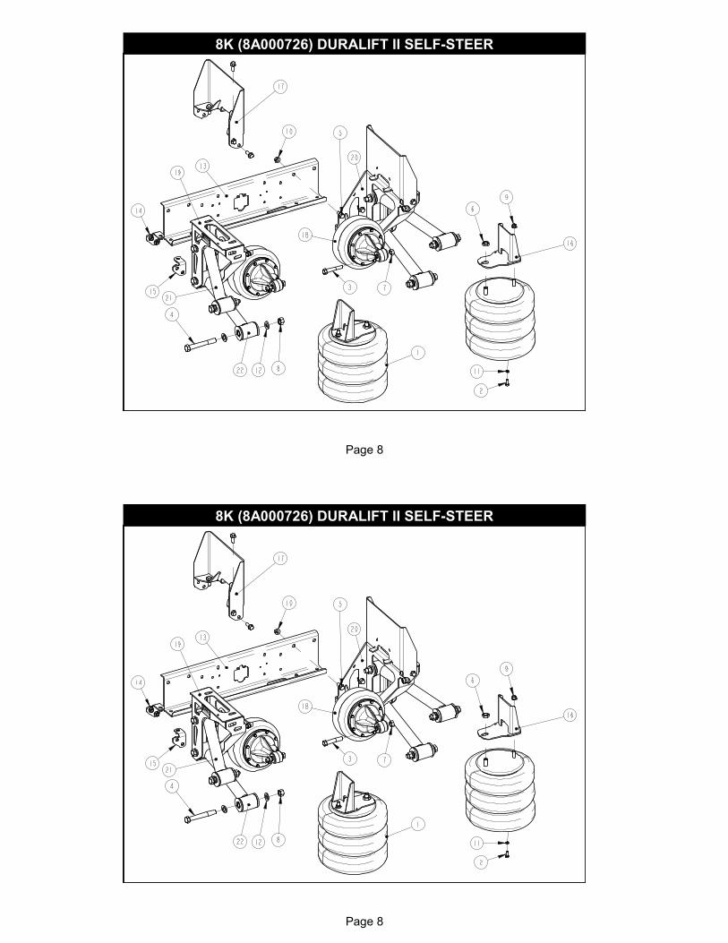
8K (8A000726) DURALIFT II SELF-STEER
Page 8
8K (8A000726) DURALIFT II SELF-STEER
Page 9
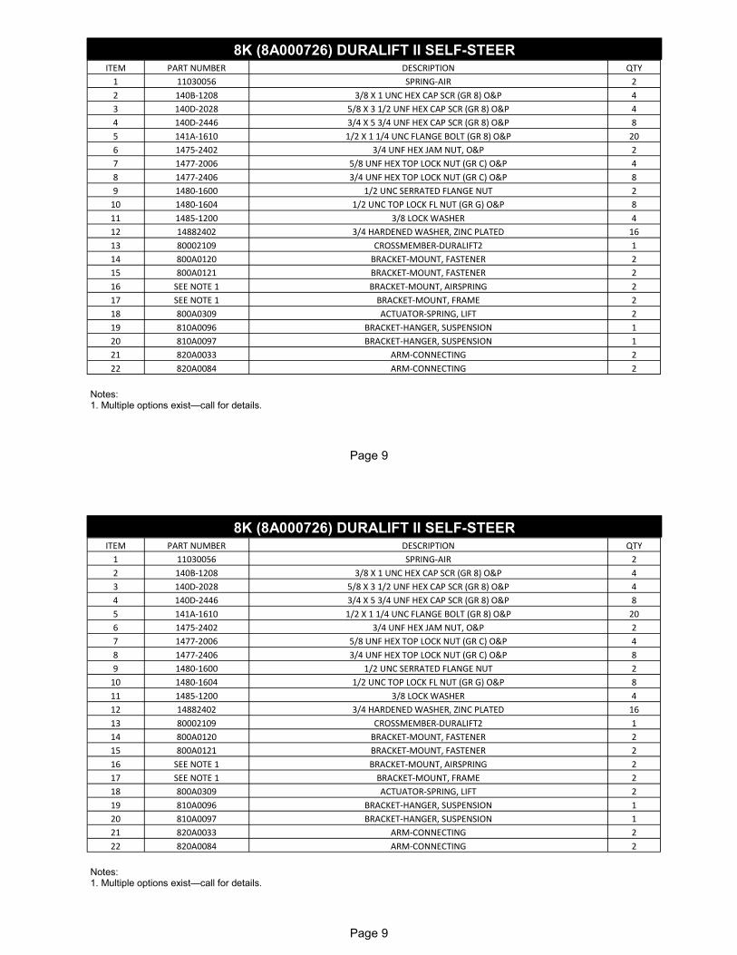
Notes: 1. Multiple options exist—call for details.
8K (8A000716) DURALIFT II SELF-STEER ITEM PART NUMBER DESCRIPTION QTY
1 11030056 SPRING-AIR 2
2 140B-1208 3/8 X 1 UNC HEX CAP SCR (GR 8) O&P 4
3 140D-2028 5/8 X 3 1/2 UNF HEX CAP SCR (GR 8) O&P 4
4 140D-2446 3/4 X 5 3/4 UNF HEX CAP SCR (GR 8) O&P 8
5 141A-1610 1/2 X 1 1/4 UNC FLANGE BOLT (GR 8) O&P 20
6 1475-2402 3/4 UNF HEX JAM NUT, O&P 2
7 1477-2006 5/8 UNF HEX TOP LOCK NUT (GR C) O&P 4
8 1477-2406 3/4 UNF HEX TOP LOCK NUT (GR C) O&P 8
9 1480-1600 1/2 UNC SERRATED FLANGE NUT 2
10 1480-1604 1/2 UNC TOP LOCK FL NUT (GR G) O&P 8
11 1485-1200 3/8 LOCK WASHER 4
12 14882402 3/4 HARDENED WASHER, ZINC PLATED 16
13 80002109 CROSSMEMBER-DURALIFT2 1
14 800A0120 BRACKET-MOUNT, FASTENER 2
15 800A0121 BRACKET-MOUNT, FASTENER 2
16 SEE NOTE 1 BRACKET-MOUNT, AIRSPRING 2
17 SEE NOTE 1 BRACKET-MOUNT, FRAME 2
18 800A0309 ACTUATOR-SPRING, LIFT 2
19 810A0096 BRACKET-HANGER, SUSPENSION 1
20 810A0097 BRACKET-HANGER, SUSPENSION 1
21 820A0033 ARM-CONNECTING 2
22 820A0084 ARM-CONNECTING 2
8K (8A000726) DURALIFT II SELF-STEER
Page 9
Notes: 1. Multiple options exist—call for details.
8K (8A000716) DURALIFT II SELF-STEER ITEM PART NUMBER DESCRIPTION QTY
1 11030056 SPRING-AIR 2
2 140B-1208 3/8 X 1 UNC HEX CAP SCR (GR 8) O&P 4
3 140D-2028 5/8 X 3 1/2 UNF HEX CAP SCR (GR 8) O&P 4
4 140D-2446 3/4 X 5 3/4 UNF HEX CAP SCR (GR 8) O&P 8
5 141A-1610 1/2 X 1 1/4 UNC FLANGE BOLT (GR 8) O&P 20
6 1475-2402 3/4 UNF HEX JAM NUT, O&P 2
7 1477-2006 5/8 UNF HEX TOP LOCK NUT (GR C) O&P 4
8 1477-2406 3/4 UNF HEX TOP LOCK NUT (GR C) O&P 8
9 1480-1600 1/2 UNC SERRATED FLANGE NUT 2
10 1480-1604 1/2 UNC TOP LOCK FL NUT (GR G) O&P 8
11 1485-1200 3/8 LOCK WASHER 4
12 14882402 3/4 HARDENED WASHER, ZINC PLATED 16
13 80002109 CROSSMEMBER-DURALIFT2 1
14 800A0120 BRACKET-MOUNT, FASTENER 2
15 800A0121 BRACKET-MOUNT, FASTENER 2
16 SEE NOTE 1 BRACKET-MOUNT, AIRSPRING 2
17 SEE NOTE 1 BRACKET-MOUNT, FRAME 2
18 800A0309 ACTUATOR-SPRING, LIFT 2
19 810A0096 BRACKET-HANGER, SUSPENSION 1
20 810A0097 BRACKET-HANGER, SUSPENSION 1
21 820A0033 ARM-CONNECTING 2
22 820A0084 ARM-CONNECTING 2
8K (8A000726) DURALIFT II SELF-STEER

Page 10
BILL OF MATERIALS FOR ASSEMBLY: 820A0033
ITEM PART NUMBER DESCRIPTION QTY
1 820A0036 ARM-CONNECTING 1
2 15000890 BUSHING 4
3 80001210 TUBE-BUSHING 2
BILL OF MATERIALS FOR ASSEMBLY: 820A0084
ITEM PART NUMBER DESCRIPTION QTY
1 15000890 BUSHING 4
2 80001210 TUBE-BUSHING 2
3 820A0083 ARM-CONNECTING 1

Page 11
ITEM PART NUMBER DESCRIPTION QTY
1 11030062 SPRING-AIR 1
2 1302-5104 ELBOW-3/8 TB, 1/4 M-NPT 1
3 1401-0808 1/4 X 1 UNC HEX CAP SCR (GR 5) 16
4 1485-0800 1/4 LOCK WASHER 16
5 15000846 BUSHING 4
6 15000891 STOP-BUMPER, CYL. 1
7 15000932 BEARING-LINEAR 2
8 80000835 TUBE-BUSHING 2
9 80001328 RING-RETAINER, AIRSPRING 4
10 80002243 PISTON-CYL., AIR 1
11 80002244 ROD-SUPPORT 1
12 80002245 CAP-CYL., AIR 1
BILL OF MATERIALS FOR ASSEMBLY: 800A0309
Page 12
8K DURALIFT II SELF-STEER AXLE ASSEMBLY BILL OF MATERIAL (830A0315)
Page 12
8K DURALIFT II SELF-STEER AXLE ASSEMBLY BILL OF MATERIAL (830A0315)

Page 13
8K DURALIFT II SELF-STEER AXLE ASSEMBLY BILL OF MATERIAL (830A0315)
* Items included in Kingpin Kit 84001997
ITEM PART # DESCRIPTION QTY ITEM PART # DESCRIPTION QTY
1 12100012 SHOCK ABSORBER, WIDE BODY 2 18 84001928 * PIN-DRAW, LOCKING 2
2 14871600 1/2 TYPE A PLAIN WASHER 4 19 84001988 * SHIM (.005) 2
3 14881602 1/2 HARDENED WASHER, ZINC PLATED 24 20 84001989 * SHIM (.010) 2
4 80000009 BUSHING-SHOCK, ACETAL 4 21 84001990 * PIN-KING, 8K 2
5 83000079 SPACER-MOUNT, SHOCK 2 22 84001995 PIN-COTTER, .13 X 1.75 2
6 84001048 TIE-ROD ASSEMBLY, 8K 1 23 84002009 ARM-STEERING, MACHINED 2
7 84001049 KEY-WOODRUFF 2 24 84002013 * SHIM (.015) 2
8 84001050 PIN-COTTER, .18 X 2.25 2 25 140D-1616 1/2 X 2 UNF HEX CAP SCR (GR 8) O&P 12
9 84001051 NUT-HEX, SLOTTED, 1.00-14 2 26 140D-1626 1/2 X 3 1/4 UNF HEX CAP SCR (GR 8) O&P 2
10 84001052 * CAP-KING PIN, 8K 4 27 140D-1630 1/2 X 3 3/4 UNF HEX CAP SCR (GR 8) O&P 2
11 84001249 KNUCKLE-STEER, LH 1 28 1474-1600 1/2 UNC HEX JAM NUT 2
12 84001250 KNUCKLE-STEER, RH 1 29 1477-1606 1/2 UNF HEX TOP LOCK NUT (GR C) O&P 4
13 84001433 * BEARING-THRUST 2 30 1480-1404 * 7/16 UNC TOP LOCK FL NUT (GR G) O&P 2
14 84001434 * CAP-BEARING 2 31 1480-1605 1/2 UNF TOP LOCK FL NUT (GR G) O&P 12
15 84001612 BRAKE ASSY –L 1 32 830A0310 AXLE-FAB., 8K DURALIFT2 1
16 84001613 BRAKE ASSY –R
17 84001699 BOLT-STOP, STEERING 2
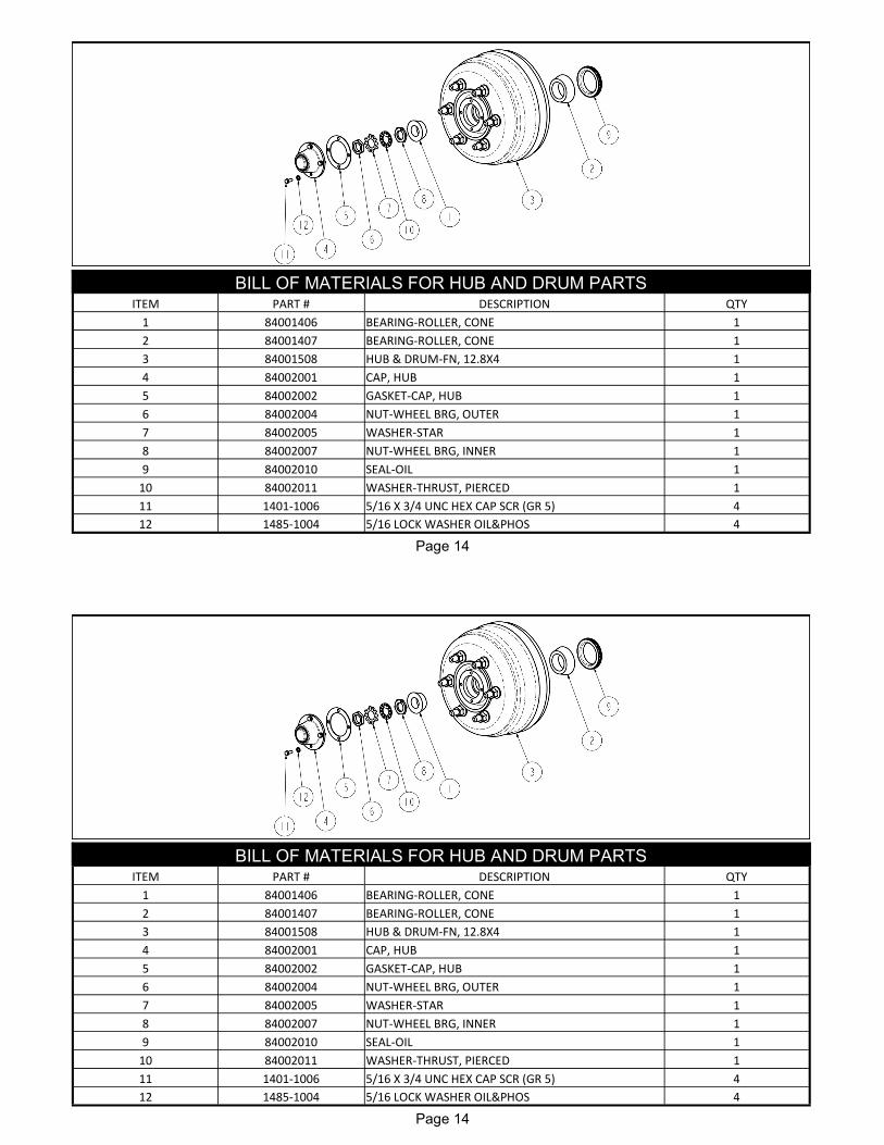
Page 14
BILL OF MATERIALS FOR HUB AND DRUM PARTS ITEM PART # DESCRIPTION QTY
1 84001406 BEARING-ROLLER, CONE 1
2 84001407 BEARING-ROLLER, CONE 1
3 84001508 HUB & DRUM-FN, 12.8X4 1
4 84002001 CAP, HUB 1
5 84002002 GASKET-CAP, HUB 1
6 84002004 NUT-WHEEL BRG, OUTER 1
7 84002005 WASHER-STAR 1
8 84002007 NUT-WHEEL BRG, INNER 1
9 84002010 SEAL-OIL 1
10 84002011 WASHER-THRUST, PIERCED 1
11 1401-1006 5/16 X 3/4 UNC HEX CAP SCR (GR 5) 4
12 1485-1004 5/16 LOCK WASHER OIL&PHOS 4