OwnerOperation and ROTARY MOWER … The mower has four grease fittings, one on each blade housing...
6
• • • Owner Operation and Maintenance Manual TO THE OWNER This is an operational and general maintenance manual only and does not cover major repair. All major repair work must be performed by an authorized BOLENS DEALER or the factory warranty is void. Bolens equipment is .carefully engineered to give good performance if properly operated and maintained. Keep your equipment clean and lubricate it as prescribed in this manual. Periodically inspect your unit and perform any upkeep maintenance necessary. Your dealer is obligated by the factory to completely assemble and service new equipment prior to first delivery, and thoroughly explain and demonstrate its operation. He will repair or replace any parts which fail due to defective material and/or workmanship during the warranty period, and also provide future repair service and supply genuine factory repair parts. IN EVENT OF ANY PROBLEM OR PARTS REQUIRED . ALWAYS CONTACT YOUR DEALER. DO NOT RETURN PARTS TO THE FACTORY. WE REQUIRE PRIOR FACTORY APPROVAL ON RETURNS, AND APPROVALS ARE ISSUED ONLY TO BOLENS DEALERS OR DISTRIBUTORS. GENERAL SAFETY PRECAUTIONS Preventing accidents is the responsibility of every e qui pment operator. The following general safety precautions must be fully understood and followed by every operator of this equipment. Review them frequently and NEVER TAKE CHANCES. BE CAREFUL BEFORE, DURING AND RIGHT AFTER USE OF ANY POWERED EQUIPMENT. ACCIDENTS CAN BE PREVENTED. (1) Regard your mower as a piece of power equipment. Teach this to all who operate the equipment. Power equipment not properly operated can be very dangerous. ROTARY MOWER ATTACHMENT 28 INCH MODEL 15100-01 (2) Do not allow children to operate powered equipment at any time. The average child is not capable of coping with the intricacies of operating a power tool. (3) Be sure you know how to stop the mower and engine quickly, in case a child, person, pet or object suddenly appears in the path of or dangerously close to unit. (4) Before using mower, clear the entire lawn area of all debris that could be thrown by the blade. Debris can be accidently ejected at high velocity out of the discharge chute causing injury to persons or pets and damage to objects the debris would strike. (5) When you mow on rough terrain, in high grass, the mower should be set at the highest cutting level to minimize possible ejection of debris. (6) MOW ONLY DURING DAYLIGHT HOURS. If you mowed after sundown you would be unable to see any object accidently left on the lawn. Artificial lighting may not illuminate the area to be mowed properly. (7) Be alert at all times. Give complete and undivided attention to the job you are doing. This would minimize the possibility of getting into dangerous situations. (8) No persons should be allowed in or near working area when mower is being used, particularly small children. This will minimize the possibility of other persons or children being injured by the mower or debris ejected by the mower. (9) Disengage mower and stop the engine when ever you leave the tractor. This will help prevent runaways and/or injury to children or another person. (10) When operating over uneven terrain and slopes use extreme care and make sure of solid firm footing at all times. This will help prevent both the operator from being thrown from unit or the unit being upset accidently. (11) Use special care when mowing near objects to prevent the blades from striking them, as severe damage could result. (12) Stop the tractor and disengage mower when any other person approaches. Do not pass or stand on the grass discharge side of the mower or allow anyone else to do so with the engine running. Objects such as wire, sticks, stones, small toys etc. can be ejected at high velocity out of the discharge chute. (13) Do not carry passengers. The passengers could fall off unit receiving injuries. (14) Engine must be stopped and spark plug wire disconnected before adjusting mower, or changing attachments. A gasoline engine can be started if the blade or P.T.O. shaft is turned in the course of making adjustments or repairs and injury would result. (15) Efficient mowing results and maximum safety can only be expected if the mower is maintained and operated correctly. Keep mower free of excess grease and oil. (16) Never wear loose clothing when operating unit. It could become entangled in moving parts causing injury to the wearer. FORM NO. 552172 PORT WISCONSIN,U.S.A. 4-70 BrentChalmers.com
Transcript of OwnerOperation and ROTARY MOWER … The mower has four grease fittings, one on each blade housing...

•
•
•
Owner Operation andMaintenance Manual
TO THE OWNER
This is an operational and general maintenance manual onlyand does not cover major repair. All major repair workmust be performed by an authorized BOLENS DEALER orthe factory warranty is void. Bolens equipment is .carefullyengineered to give good performance if properly operatedand maintained. Keep your equipment clean and lubricateit as prescribed in this manual. Periodically inspect yourunit and perform any upkeep maintenance necessary.
Your dealer is obligated by the factory to completelyassemble and service new equipment prior to first delivery,and thoroughly explain and demonstrate its operation. Hewill repair or replace any parts which fail due to defectivematerial and/or workmanship during the warranty period,and also provide future repair service and supply genuinefactory repair parts.
IN EVENT OF ANY PROBLEM OR PARTS REQUIRED. ALWAYS CONTACT YOUR DEALER. DO NOT
RETURN PARTS TO THE FACTORY. WE REQUIREPRIOR FACTORY APPROVAL ON RETURNS, ANDAPPROVALS ARE ISSUED ONLY TO BOLENSDEALERS OR DISTRIBUTORS.
GENERAL SAFETY PRECAUTIONS
Preventing accidents is the responsibility of everyequi pment operator. The following general safetyprecautions must be fully understood and followed byevery operator of this equipment. Review them frequentlyand NEVER TAKE CHANCES. BE CAREFUL BEFORE,DURING AND RIGHT AFTER USE OF ANY POWEREDEQUIPMENT. ACCIDENTS CAN BE PREVENTED.
(1) Regard your mower as a piece of power equipment.Teach this to all who operate the equipment. Powerequipment not properly operated can be very dangerous.
ROTARY MOWERATTACHMENT
28 INCH
MODEL 15100-01
(2) Do not allow children to operate powered equipmentat any time. The average child is not capable of coping withthe intricacies of operating a power tool.
(3) Be sure you know how to stop the mower and enginequickly, in case a child, person, pet or object suddenlyappears in the path of or dangerously close to unit.
(4) Before using mower, clear the entire lawn area of alldebris that could be thrown by the blade. Debris can beaccidently ejected at high velocity out of the dischargechute causing injury to persons or pets and damage toobjects the debris would strike.
(5) When you mow on rough terrain, in high grass, themower should be set at the highest cutting level tominimize possible ejection of debris.
(6) MOW ONLY DURING DAYLIGHT HOURS. If youmowed after sundown you would be unable to see anyobject accidently left on the lawn. Artificial lighting maynot illuminate the area to be mowed properly.
(7) Be alert at all times. Give complete and undividedattention to the job you are doing. This would minimizethe possibility of getting into dangerous situations.
(8) No persons should be allowed in or near working areawhen mower is being used, particularly small children. Thiswill minimize the possibility of other persons or childrenbeing injured by the mower or debris ejected by the mower.
(9) Disengage mower and stop the engine when ever youleave the tractor. This will help prevent runaways and/orinjury to children or another person.
(10) When operating over uneven terrain and slopes useextreme care and make sure of solid firm footing at alltimes. This will help prevent both the operator from beingthrown from unit or the unit being upset accidently.
(11) Use special care when mowing near objects to preventthe blades from striking them, as severe damage couldresult.(12) Stop the tractor and disengage mower when any otherperson approaches. Do not pass or stand on the grassdischarge side of the mower or allow anyone else to do sowith the engine running. Objects such as wire, sticks,stones, small toys etc. can be ejected at high velocity out ofthe discharge chute.(13) Do not carry passengers. The passengers could fall offunit receiving injuries.(14) Engine must be stopped and spark plug wiredisconnected before adjusting mower, or changingattachments. A gasoline engine can be started if the bladeor P.T.O. shaft is turned in the course of makingadjustments or repairs and injury would result.(15) Efficient mowing results and maximum safety canonly be expected if the mower is maintained and operatedcorrectly. Keep mower free of excess grease and oil.(16) Never wear loose clothing when operating unit. Itcould become entangled in moving parts causing injury tothe wearer.
FORM NO. 552172 PORT WASHI~GTON, WISCONSIN,U.S.A. 4-70
BrentChalmers.com

MODEL NUMBER
•
•
•
•
Figure 4
Figure 3
ASSEMBLY
This unit is shipped complete with all parts required tomount it to your HUSKY tractor.
(1) Attach the two gauge wheels to the mower assemblyby securing the wheels to their respective axles with a flatwasher on each side of the wheel and cotter key and theninserting the axle into the outside second notch of thewheel mounting bracket on the rear of the mower deck.Secure the axles with the KLIK pins supplied. See figure 3.
MOUNTING
To attach mower to the tractor, slide the mower under thetractor. Bring the attachment arms up to the hitch bracketsof the tractor and install hitch pins from outside in; securewith spring cotter. On tractors equipped with lift kit,position the tractOl,' attachment lift lever in the full forwardposition. Attach lift chains to lift arms using the flat washerand spring cotter. Grasp the Handle "A" of the springloaded mower drive pulley (see figure 4); pull the springloaded pulley in a clockwise direction with the right handand slip the belt onto the tractorP.T.O. pulley with the lefthand.
LEVELING THE MOWER
For best cutting results, it is important that the mower beleveled from front to back. Set mower on the gauge wheelson a flat level area, and check the tractor tire pressures, 30Ibs. in the rear, 30 Ibs. in front.
NOTE: Be certain gauge wheels are positioned in the sa~cutting height position. Place mower on ground level. Usinga level on the mower deck check for front to back leveling.Should adjustment be required, refer to "A" figures 5 and6. If mower is too high in front, tum screws "A" on bothsides of mower, equal turns counterclockwise, until moweris level. If it is too low in front, tum screws "A" on bothsides of mower, equal turns clockwise, until mower is level.
I CAUTION: DO NOT use the mower deck as a step plate.j
i
o 0
172·1972SPACER
171-9672KLICK
PIN
189-0234WASHER
000000000000
170-3011SPRINGCOTTER
IJ...·\, 11
171·9742GAUGE WHEEL
AXLE
171-9324CLEVIS
PIN
172-1268 172-1970LINK R.H. ARM ASSEMBLY
rllJl\1
t rttT\t110-0349COTTER
PIN
U&170-9622CLEVIS
PIN
~."
181036GAUGE WHEEL
Figure 2LOOSE PARTS
172-1971L.H. ARM ASSEMBLY
••
(17) Always wear shoes when operating unit to give yourfeet as much protection as possible.
(18) Do not allow adults to operate unit without properinstructions including all safety instructions. In doing so,you will be sure they know how to operate unit properlyand also are aware of all the safety precautions.
(19) Study your manual. Know your equipment beforeoperating it. Take time to operate the unit in the safestmanner.
(20) Always follow manufacturer's operational suggestionsfor most efficient and safest operation of unit.
(21) Always look back to be certain no one is in the waybefore using reverse. This will avoid the possibility ofrunning over any children, persons or pets who might be inthe area in back of the unit.
To ensure prompt service when repairs or adjustments arerequired, your Bolens Dealer must have the followinginformation:
For your own personal reference, fill in the space providedbelow.Model Number of Unit _
Serial Number of Unit _
Your Bolens dealer has available a master Parts List foryour unit. He can. identify any parts you may require andfurnish genuine factory replacements.
BrentChalmers.com

•
•
•
•
OPERATION
CAUTION: BEFORE USING MOWER, REMOVESTONES, WIRE, ETC. FROM AREA TO BE MOWED. BESURE TO A VOID STRIKING PROTRUDING OBJECTSSUCH AS PIPES, ROO1S, AND EARTH MOUNDS WITHCUTTING BLADES AS THIS COULD RESULT INDAMAGE TO THE MOWER. NEVER PLACE HANDS ORFEET UNDER MOWER BASE WHEN ENGINE ISRUNNING.
There is one control for operating the mower: a tractorpower take-off lever for engaging the mower blades. Atractor lift lever kit for raising and lowering the mower canbe purchased as an optional accessory.
BE SURE THE TRACTOR POWER TAKE-OFF LEVER(P.T.O.) IS DISENGAGED AND THE TRACTOR GEARSIllFT LEVER IS IN NEUTRAL BEFORE STARTINGTHE ENGINE. For best results the engine should run at fullthrottle to maintain sufficient blade speed. The groundspeed should be controlled with the tractor gear shift andnot by changing throttle setting. The engine governor willcontrol for any increase or decrease in power requirements.If the engine begins to lag in heavy cutting, the groundspeed should be reduced by shifting to a lower gear speed.The mower will not cut clean when the ground speed is toohigh or when the blade speed drops due to overload.
For transport, disengage the tractor P.T.O. and raise themower.
- ... ~- ...~- ----
HEIGHT OF CUT
The cutting height is regulated by raising or lowering thetwo rear gauge wheels. The approximate cutting heights are1-3/4,2-1/4 and 2-3/4 inches.
CUTTING BLADES
For efficient cutting, maintain sharp cutting edges on theblades at all times. When sharpening blades, be sure to grindor file equal amounts off both ends to maintain balance, asan unbalanced blade will cause excessive vibration andultimately premature blade bearing failure. Always checkblades on a blade balancer before reinstallation.
DRIVE BELTS
The mower has two drive belts. These belts are underconstant spring tension and require no adjustment. (Seefigures 7 and 8.)
To replace the drive belt, remove the 3/8 inch nut "A" andlockwasher holding the spring loaded drive pulley and idlerarm. Remove the 5/16 inch cap screw "B" and raise theidler arm up and away from pulley; then remove belt.Install new belt and reassemble.
To replace blade drive belt proceed as follows:
Remove the two 3/8 inch hex nuts "C" on top of beltcover, figure 7. Remove the nine hex head capscrews "D"securing belt cover to mower deck. Remove the two hexhead capscrews "F" securing the two hitch assemblies "E"to mower. Raise end of hitch assemblies as far as possibleand remove belt cover. Remove spring loaded drive pulleyidler arm as described above. Remove blade drive belt.Reverse the above procedure to install belt.
Figure 7
BrentChalmers.com

LUBRICATION
The mower has four grease fittings, one on each bladehousing located on the top side of the mower deck and oneon the input sheave; lubricate grease fittings every 8 hoursof operation. Oil all other working parts, especially gaugewheel axles, and idler arm pivots with light oil.
CARE AND MAINTENANCE
'lour mower is equipped with a hose fitting insert whichenables you to wash out the underside of your mowerwithout removing it from the tractor. To attach hose, shutoff tractor engine, remove the plastic cap from the hosefitting. Attach hose, lower mower to its lowest cuttingposition, start tractor engine.
NOTE: Be sure tractor shift lever is in NEUTRAL.
Engage mower blades, then turn water on full force forapproximately 3 to 4 minutes. Shut off water and allowblades to continue running for several more minutes. Thiswill partially air-dry the under side of the deck. Shut offengine, remove hose and replace hose fitting cap.
NOTE: ALWAYS REPLACE HOSE FIITING CAPAFTER WASHING OUT DECK.
Periodically place a few drops of oil on all linkage joints,especially on idler arm pivots after washing out mowerdeck. Regularly check the complete unit for loose screwsand nuts.
•
Bolens reserves the right to change specifications, addimprovements or discontinue the manufacture of any of itsequipment without notice or obligation to purchasers of itsequipment when equipment was purchased prior todecision to make changes, add improvements or discontinuemanufacture.
Bolens' approval of the use of attachments manufacturedby other manufacturers is lirrJted to assurance that such usewill not void Bolens warranty on the Bolens equipment towhich the outside manufactured attachments are adapted.The responsibility for the design, performance, durability,safety in operation, service repair availability, and warrantyobligation remain with the outside manufacturer. Bolensspecifically excludes from its warranty obligation all suchoutside manufactured attachments.
Bolens warranty will be voided if unapproved attachmentsare adapted to use with Bolens equipment and are so used.
•
••
BrentChalmers.com

• Installation InstructionsDUAL RANGE KIT
MODEL 15106-01
"A" "B"
"H" '''E'' "'0"
"G" "c"
"F"
6. Insert nylon bushings #171-7263 into hole "D" ofsteering support; see Figure 2.
7. Place one #170-0821 flat washer onto shaft of idlerassembly. Install shaft into nylon bushings previouslyinstalled in hole "D" of steering support.
Figure 2
5. Remove drive belt "e", Figure 2. Refer to OwnersManual, Figures 13 and 14 for removal procedure.
IDLER ASSEMBLY
INTERMEDIATEPULLEY ASSEMBLY
"V" BELT172·2993
2. Remove battery (disconnect negative (-) cable first),drain gasoline tank, remove spark plug and tip tractor up onend on its rear fender.
1. Count and check parts against Figure 1.
•SPRING NYLON BUSHING RETAINING RING BRACKET172-3117 171-7263 111-3527 171-3686 8. Place remaining #170-0821 flat washer over upper end
of idler shaft and secure with one #111-3527 retainer ring.
t::··_-O 009. Remove nut from rear carriage bolt on rear right handmower hanger bracket. Install #171-3686 spring bracket"A" over bolt and secure with nut and lockwasherj seeFigure 3.
•
BELT GUIDE FLAT WASHER LOCKWASHER HEX HEAD172-2988 170-0821 110-0241 CAPSCREW
1/4-20 x 1Figure 1 LOOSE PARTS 110-6840
NOTE
TO PREVENT THE TRACTOR FROM TIPPINGDOWN ACCIDENTALLY CAUSING INJURIES,THE TRACTOR SHOULD BE SECURELY HELD INTHE VERTICAL POSITION WITH A CHAIN ANDHOIST.
3. Remove belt guide "A" and studs, Figure 2.
4. Remove P.T.O. belt "B", Figure 2.
FORM NO. 552298 PORT WA SHIN GTON, WI sea NSIN, U.S.A. 11/70PRINTED IN U.S ,A.
BrentChalmers.com
10. Rook idler spring #172-3117 into spring bracket andthen into hole provided in idler arm. See "B", Figure 3.
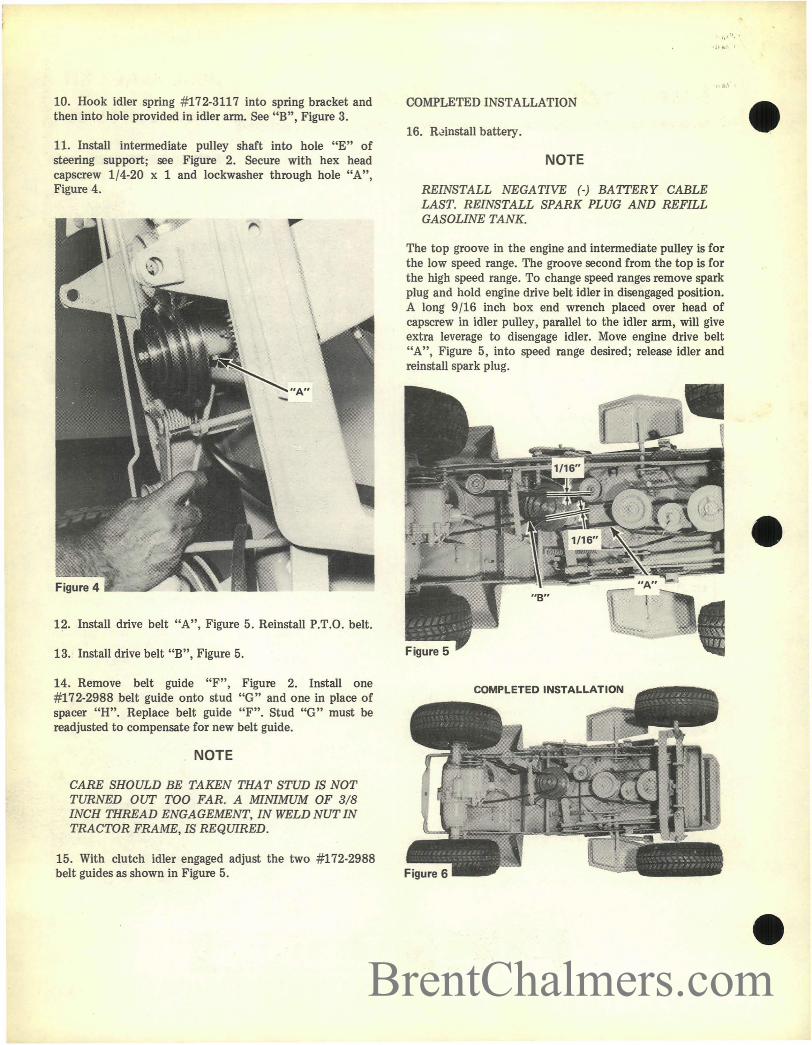
11. Install intermediate pulley shaft into hole "E" ofsteering support; see Figure 2. Secure with hex headcapscrew 1/4-20 x 1 and lockwasher through hole "A",Figure 4.
12. Install drive belt "A", Figure 5. Reinstall P.T.O. belt.
13. Install drive belt "B", Figure 5.
14. Remove belt guide "F", Figure 2. Install one#172-2988 belt guide onto stud "G" and one in place ofspacer "R". Replace belt guide "F". Stud "G" must bereadjusted to compensate for new belt guide.
NOTE
CARE SHOULD BE TAKEN THAT STun IS NOTTURNED OUT TOO FAR. A MINIMUM OF 3/8INCH THREAD ENGAGEMENT, IN WELD NUT INTRACTOR FRAME, IS REQUIRED.
15. With clutch idler engaged adjust the two #172-2988belt guides as shown in Figure 5.
';1'..' I
COMPLETED INSTALLATION
16. R~install battery.
NOTE
REINSTALL NEGATIVE (-) BAITERY CABLELAST. REINSTALL SPARK PLUG AND REFILLGASOLINE TANK.
The top groove in the engine and intermediate pulley is forthe low speed range. The groove second from the top is forthe high speed range. To change speed ranges remove sparkplug and hold engine drive belt idler in disengaged position.A long 9/16 inch box end wrench placed over head ofcapscrew in idler pulley, parallel to the idler arm, will giveextra leverage to disengage idler. Move engine drive belt"A", Figure 5, into speed range desired; release idler andreinstall spark plug.
•
•
•BrentChalmers.com