Owner’s Manual - imgix Manuals... · have chosen other than what characteristics individual...
24
Owner’s Manual
Transcript of Owner’s Manual - imgix Manuals... · have chosen other than what characteristics individual...
Owner’s Manual

Hello from the Tone FarmThank You for choosing the CabClone™ IR and Welcome to the MESA/Boogie Family! This product benefits from the same strict code of fine instrument building employed that all MESA/Boogie Products share and we hope you find years of inspiration and enjoyment through its features and sounds. Like our amplifiers and cabinetry, this device was built by hand in our one and only Shop in Petaluma California by the same talented craftspeople that build our hand-made vacuum tube amplifiers … most with us for decades.
This operating guide will help you attain the most from your new product and hopefully answer most interfacing and operating questions you might have. However, should you find you need additional help or advice for your specific applications and/or needs, don’t hesitate to call us directly and one of our Product Specialists will be happy to assist you.

Table of ContentsPRECAUTIONSOVERVIEW ____________________________________________________________________________________ 1-2HELPFUL HINTS ________________________________________________________________________________ 3
REAR PANEL (Interface Connections) INPUT: LINE ____________________________________________________________________________________ 3INPUT: FROM AMP SPKR OUT _____________________________________________________________________ 3OUTPUT: TO SPKR______________________________________________________________________________ 3-6MIDI THRU _____________________________________________________________________________________ 7MIDI IN ________________________________________________________________________________________ 7POWER: 18VDC/1 AMP ___________________________________________________________________________ 7USB ___________________________________________________________________________________________ 7LIFT/GROUND __________________________________________________________________________________ 8180/PHASE _____________________________________________________________________________________ 8D.I. OUTPUT ____________________________________________________________________________________ 8LINE OUT (DRY) _________________________________________________________________________________ 8HEADPHONES __________________________________________________________________________________ 8
TOP PANEL CONTROLS CLIP LEDs _____________________________________________________________________________________ 9INPUT LEVEL ___________________________________________________________________________________ 9PRESENCE _____________________________________________________________________________________ 9OUTPUT LEVEL _________________________________________________________________________________ 9CAB SELECT ROTARY & BANK SELECT SWITCH _____________________________________________________ 9
ORGANIZING AND LOADING IR’s _________________________________________________________________ 10EXAMPLE LIVE AND STUDIO CONNECTION DIAGRAMS ____________________________________________ 11-15SPECIFICATIONS _______________________________________________________________________________ 16
READ AND FOLLOW INSTRUCTIONS OF PROPER USAGE.
IMPORTANT SAFETY INSTRUCTIONSRead these instructions.
Keep these instructions.
Heed all warnings.
Follow all instructions.
Do not use this apparatus near water.
Clean only with dry cloth.
Do not block any ventilation openings. Install in accordance with the manufacturer’s instructions.
Do not install near any heat sources such as radiators, heat registers, stoves, or other apparatus that produce heat.
Do not defeat the safety purpose of the polarized or grounding-type plug. A polarized plug has two blades with one wider than the other. A grounding type plug has two blades and a third grounding prong. The wide blade or the third prong are provided for your safety. If the provided plug does not fit into your outlet, consult an electrician for replacement of the obsolete outlet.
Protect the power cord from being walked on or pinched particularly at plugs, convenience receptacles, and the point where they exit from the apparatus.
Only use attachments/accessories specified by the manufacturer.
Unplug this apparatus during lightning storms or when unused for long periods of time.
Refer all servicing to qualified service personnel. Servicing is required when the apparatus has been damaged in any way, such as power-supply cord or plug is damaged, liquid has been spilled or objects have fallen into the apparatus, the apparatus has been exposed to rain or moisture, does not operate normally, or has been dropped.
CAUTION: When using the Internal Load with high output amplifiers (100+ watts), do not set the amplifier’s Output (Master) all the way up. This can stress the amp and prematurely wear the output tubes, the same as if it were connected to a speaker. If the CCIR chassis gets hot to the touch, back down the Master Volume. Your amp will thank you.
No naked flame sources, such as lighted candles, should be placed on the apparatus.
The apparatus shall not be exposed to dripping or splashing and no objects filled with liquids, such as vases, shall be placed on the apparatus.
WARNING: To reduce the risk of fire or electric shock, do not expose this apparatus to rain or moisture.
The plug is the mains disconnect. The plug should remain accessible after installation.
WARNING: EU: permission from the Supply Authority is needed before connection.
WARNING: Always make sure proper load is connected before operating the unit. Failure to do so could pose a shock hazard and may result in damage to the amplifier.
Do not expose to direct sunlight or extremely high temperatures.
To avoid damaging your speakers and other playback equipment, turn off the power of all related equipment before making the connections.
Do not use excessive force when handling buttons, switches and controls. Do not use solvents such as benzene or paint thinner to clean the unit.
Always connect to a power supply that meets the power supply specifications listed on the rear of the unit. Make certain grounding conforms with local standards.

Operating Instructions OVERVIEW
The CabClone IR is a digital Cabinet Simulator/Impulse Response Reader that holds 16 instantly accessible popular MESA speaker cabinet and iconic microphone combinations in Presets of IR Captures within its two Banks of 8 User Preset locations. These can be accessed from the Top Panel BANK Switch and CAB SELECT rotary control manually or via MIDI program change commands. It also provides an on-board reactive Speaker load that is automatically activated to protect your amplifier and make it safe to record silently Direct or feed a Live console and run your amp with no cabinet for an in-ear monitor stage setup where cabinet bleed is not desirable or very low stage volumes are required.
Along with the 16 Factory supplied IR PRESETS, there is ample room to download and save hundreds of third party IRs within the CabClone IR’s processor memory. Once accessed and viewed on your computer via the standard USB connection, IRs can easily be dragged and dropped as separate files — one for each of the CabClone’s 16 User Locations within the two Banks. This flexibility allows you to instantly access the IR PRESETS within the two Banks for your own playing, recording, or live performance sets.
Interfacing options appear in the form of Inputs and Outputs for speaker cabinet signals and line level signals to and from the unit. MIDI Program Change commands are supported and can be used to access the 16 IR PRESETS via the MIDI IN DIN jack. A MIDI THRU jack is also provided to pass those program change messages on to other devices that recognize MIDI commands.
The Internal Reactive load provides an impedance-matched (per your choice at purchase) safe way to forego the Speaker Cabinet or internal Combo speaker and record Direct or send a DI signal silently to a Live (FOH/Monitor) console. A speaker cabinet may also be used simultaneously for stage sound and monitoring your amplifier through guitar cabinets, this having no effect on the IR Preset you have chosen other than what characteristics individual speakers may impart on the output transformer. The Internal load is defeated automatically when a cable is connected to the ¼” TO SPKR Output. Make sure you choose the proper impedance CabClone IR, as they are built specifically for 4, 8 (most common) or 16 Ohm applications. The load portion of the CabClone IR is a reactive circuit that functions regardless of whether or not power is supplied to the unit. You may use the Internal Reactive load without powering up the unit with the power supply.
An internal signal-triggered Cooling Fan is included to ensure proper operating temperature. The small fan spins only when there is sufficient power being generated by the amplifier in use.
The CabClone IR Inputs include: LINE ¼” phono, FROM AMP SPEAKER OUT Input ¼” phono, MIDI IN 5-Pin Standard DIN, POWER/18 Volt DC Power Supply (Included) Connection - standard, USB Port (For connecting to your Computer).The CabClone IR Outputs include: OUTPUT (To Speaker) ¼” phono, MIDI THRU standard 5-Pin DIN, 3-Pin Male XLR balanced DI OUTPUT, LINE OUT (DRY/Non-Simulated) ¼” phono and a HEADPHONES Stereo ¼” phono.
Moving to the Top Panel of the Unit, the upper three Controls Right to Left are:
CLIP LEDs (INPUT): Provide indication of the Input Signal strength from either your amplifier’s Speaker Output (preferred) or, if a preamp is your Source, the Output of your preamp. Optimal level illuminates the Yellow LED. The Red LED INDICATES YOU ARE OVERLOADING THE INPUT STAGE OF THE CCIR. Reduce the Input Level Control or Output level strength at either your amplifier’s MASTER output stage if you are using the Power section, or the Preamp Output level control until the Red LED no longer illuminates.
PAGE 1

INPUT: Controls the Input Signal to the unit from the two ¼” INPUTS, LINE and FROM AMP SPKR OUT ¼” jacks. This control also sets the Output Signal Level at the LINE OUT (DRY) 1/4” output jack.
PRESENCE: Provides a global EQ control that affects the XLR balanced Output and the ¼” Stereo HEADPHONES Output and offers enhanced brightness and cut in the upper frequencies when rotated clockwise or high frequency roll-off when dialed in the counterclockwise direction.
OUTPUT: Controls the signal level to the Recording Interface/console or other destination via the DI OUTPUT and ¼” HEAD-PHONES jack (not the ¼” LINE OUT (DRY) output.
Below those controls, on a lower horizontal line, ride the 8-Position CAB SELECT Rotary and the BANK SELECT mini toggle switch, which allow selection of the IR Presets contained in either BANK A or B, depending on which is selected.
The CabClone IR ships with 16 MESA Proprietary Cabinet Impulse Responses, loaded into the two Banks of 8 Presets. BANK A contains the “LIVE” IRs, which were recorded with Dynamic and Ribbon Microphones and BANK B contains IRs recorded with Con-denser and Ribbon microphones, for the “STUDIO” versions of the same eight cabinets appearing in the same order. This allows you to compare the microphone choices by simply flipping the BANK switch between A and B Banks.
The Factory loaded Cabinet Models captured two ways, LIVE/BANK A and STUDIO/BANK B, are as follows and loaded in the 8 Preset CAB SELECT Locations:
1. 4x12 RECTO STANDARD – Celestion V30s – MESA Proprietary – 8 Ohm
2. 4x12 RECTO TRADITIONAL - Celestion V30s – MESA Proprietary – 8 Ohm
3. 2x12 RECTO HORIZONTAL - Celestion V30s – MESA Proprietary – 16 Ohm
4. 1x12 RECTO - Celestion V30 – MESA Proprietary – 8 Ohm
5. 1x12 THIELE - Celestion C90 – MESA Proprietary – 8 Ohm
6. 2x12 LONE STAR - Celestion C90 – MESA Proprietary – 16 Ohm
7. 1x12 LONE STAR 23 - Celestion C90 – MESA Proprietary – 8 Ohm
8. 1x12 CALIFORNIA TWEED 23 – Jensen 100w Alnico “Blackbird” – 8 Ohm
The BANK A/LIVE versions were captured with a Shure SM57 Dynamic microphone and a Beyer M160 Ribbon microphone on each cabinet.
BANK B/STUDIO versions were captured using a Tube Neumann U67 Condenser mic and a Royer 122 Ribbon mic on each cab.
The two versions can be compared on any of the 8 Cabinet Types by simply toggling between BANK A and BANK B on the BANK SELECT mini toggle switch.
These 16 Factory loaded IR Presets can be moved to any of the 2 Bank’s 8 Preset locations or removed altogether to make room for IRs you might already have elsewhere or prefer to purchase and download into the CabClone IR. The Cab Library folder can be used as a storage location while transferring the Factory IRs, and for keeping any purchased MESA or 3rd party IRs for easy access later on. Depending on the size of the files, the Cab Library can hold as many as several hundred IRs.
The IR lengths are 100ms, which offers incredible resolution for high quality IRs. Longer IRs you may download into the CabClone will play just fine, but will be truncated to 100ms.
PAGE 2
Helpful Hints
We have provided within the CabClone IR’s 16 IR Presets, the very best, most accurate captures of our most popular MESA Cabinetry recorded in a world class studio environment using the most iconic combinations of microphones.
Sound, like color, is subjective. No two artists hear or see things alike. With the vast number of listening environments, including headphones, monitors — be they recording or Live PA — we feel we’ve provided something for almost any need and every style in the Factory loaded Presets. From cabinetry that excels at open sounding, transparent cleans, to vintage-voiced open-back cabs that sing and howl for semi-saturated Blues overdrive, to closed-back 2x12s and Quad Boxes that chunk and grind for gained-up, Heavy Rock, there’s a cabinet and a voice for everyone here in the CabClone IRs 16 Presets. Spend the time matching up your different sounds to the included Presets and you will quickly realize what a powerful tool you’ve chosen for trouble free DI recording and Live applications.
Use caution when setting the Master Volume on your amp. While the CCIR can handle up to 150 Watts, setting the amp extremely loud is usually not the best approach to obtaining great Tone. Setting the Master Volume all the way up will generally sound less desirable and mean that you sacrifice most of the control over the character and response you’ve dialed in with the preamp. It will also wear out your power tubes faster, the same as if the amp were connected to a speaker. In most cases, you’ll find the sweet spot is somewhere between 11:00-2:00 on the amp’s Master Volume. In that region you’ll be introducing plenty of power section color and fullness, but you will still retain much of the preamp’s control over the sound and the response. When the power section is driven to full clip, the sound you’ve dialed up on the preamp’s controls will be overshadowed by the power section’s behavior, good or bad.
The firmware inside the device includes many error detection mechanisms. When an error is detected, the red clip LED will blink an error code. To reset the error, unplug and reconnect the power supply, or push the Boot switch located through a small hole on the bottom of the unit.
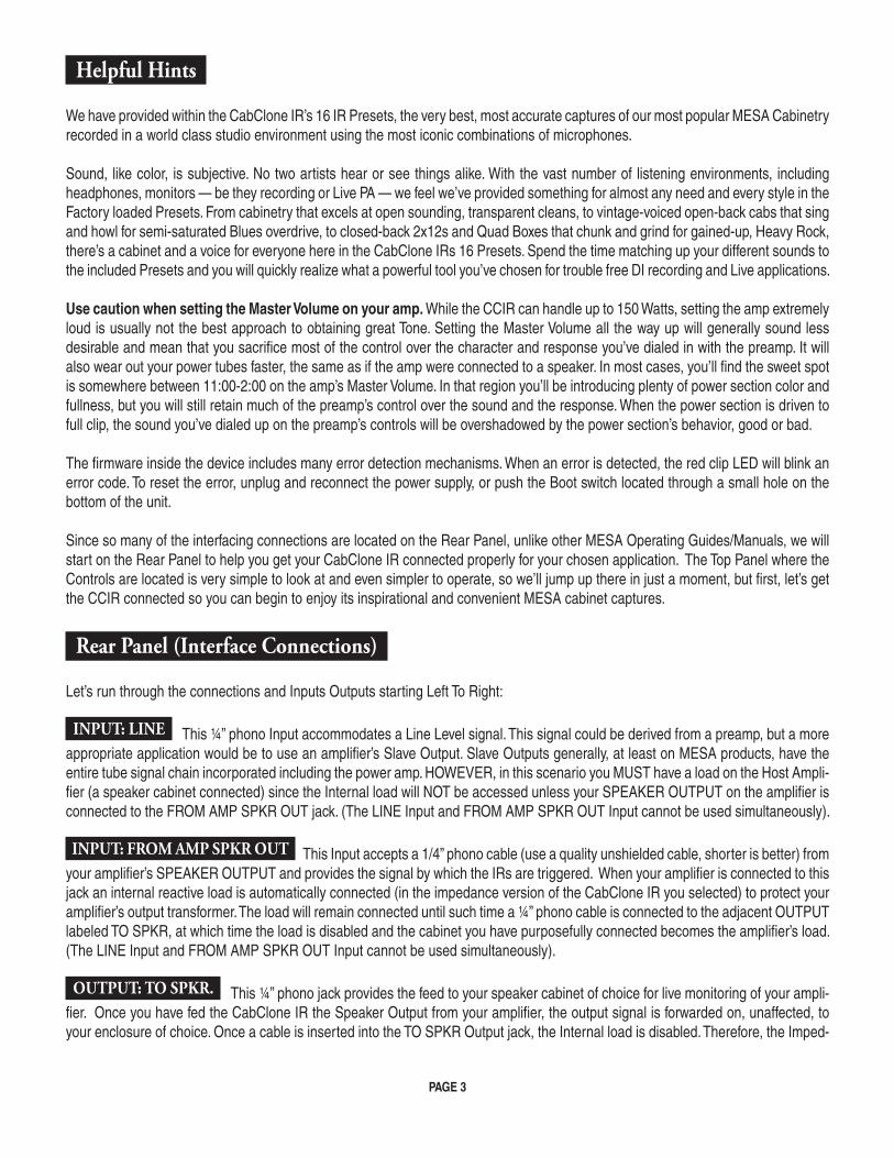
Since so many of the interfacing connections are located on the Rear Panel, unlike other MESA Operating Guides/Manuals, we will start on the Rear Panel to help you get your CabClone IR connected properly for your chosen application. The Top Panel where the Controls are located is very simple to look at and even simpler to operate, so we’ll jump up there in just a moment, but first, let’s get the CCIR connected so you can begin to enjoy its inspirational and convenient MESA cabinet captures.
Rear Panel (Interface Connections)
Let’s run through the connections and Inputs Outputs starting Left To Right:
INPUT: LINE This ¼” phono Input accommodates a Line Level signal. This signal could be derived from a preamp, but a more appropriate application would be to use an amplifier’s Slave Output. Slave Outputs generally, at least on MESA products, have the entire tube signal chain incorporated including the power amp. HOWEVER, in this scenario you MUST have a load on the Host Ampli-fier (a speaker cabinet connected) since the Internal load will NOT be accessed unless your SPEAKER OUTPUT on the amplifier is connected to the FROM AMP SPKR OUT jack. (The LINE Input and FROM AMP SPKR OUT Input cannot be used simultaneously).
INPUT: FROM AMP SPKR OUT This Input accepts a 1/4” phono cable (use a quality unshielded cable, shorter is better) from your amplifier’s SPEAKER OUTPUT and provides the signal by which the IRs are triggered. When your amplifier is connected to this jack an internal reactive load is automatically connected (in the impedance version of the CabClone IR you selected) to protect your amplifier’s output transformer. The load will remain connected until such time a ¼” phono cable is connected to the adjacent OUTPUT labeled TO SPKR, at which time the load is disabled and the cabinet you have purposefully connected becomes the amplifier’s load. (The LINE Input and FROM AMP SPKR OUT Input cannot be used simultaneously).
OUTPUT: TO SPKR. This ¼” phono jack provides the feed to your speaker cabinet of choice for live monitoring of your ampli-fier. Once you have fed the CabClone IR the Speaker Output from your amplifier, the output signal is forwarded on, unaffected, to your enclosure of choice. Once a cable is inserted into the TO SPKR Output jack, the Internal load is disabled. Therefore, the Imped-
PAGE 3
ance you’ve chosen for the internal safety load when purchasing your CCIR does not affect the impedance load at this jack. Once the internal load is disabled in this manner, the load impedance is determined by the Speaker Cabinet(s) you are connecting here.
NOTE: It is possible to feed more than one speaker cabinet from the TO SPKR Output. On MESA Cabinetry, use the PARALLEL Jack on the rear jack plate to “daisy-chain” cabinets. Please note the overall combined impedance and make sure you are connecting the correct load to your amplifier. The combined impedance of two cabinets connected in parallel will be ½ of an individual cabinet’s impedance (i.e. 2 x 8 Ohm cabinets in parallel creates a 4 Ohm load). In this scenario, connect the 4 Ohm output of the amplifier to the FROM AMP SPKR OUT on the CCIR. Next, connect the TO SPKR output of the CCIR to the 8 Ohm input of the first cabinet. Lastly, connect the Parallel out of the first cabinet to the 8 Ohm input of the second cabinet. This would be a safe and proper impedance match. On non-MESA cabinetry (or older MESA cabinetry that does not have a PARALLEL jack), a parallel box can be used to create the same result (See diagrams on the following pages for proper connection).
PAGE 4

PAGE 5
INTERNAL LOAD
OHMS 150W RMS
18VDC1 AMPINPUTS
FROM AMPSPKR OUT
TO SPKR
LINE OUT (DRY)LINE / INST
MIDI THRU MIDI IN HEADPHONESUSB DI OUTPUTPHASE
(OPTIONAL)
GROUND
LIFT
180º
OUTPUT
WARNING:Read User Manual Before Use.
Do Not Expose To Rain Or Moisture.
CAUTION:Do Not Set Amp Output To Max -
Damage May Occur.®
MADE IN PETALUMA, CALIFORNIA, USA WITH THE WORLD’S FINEST MATERIALS
FOH CONSOLE
4 OHM OUT
8 OHM IN
8 OHM IN
PARALLELOUT
8 OHM GUITAR CABINETS(OPTIONAL)
PA SPEAKERS
GUITAR AMP
LIVE ON STAGE WITH TWO 8 OHM CABINETS
(SHOWN WITH 8 OHM CABCLONE™ IR)

PAGE 6
INTERNAL LOAD
OHMS 150W RMS
18VDC1 AMPINPUTS
FROM AMPSPKR OUT
TO SPKR
LINE OUT (DRY)LINE / INST
MIDI THRU MIDI IN HEADPHONESUSB DI OUTPUTPHASE
(OPTIONAL)
GROUND
LIFT
180º
OUTPUT
WARNING:Read User Manual Before Use.
Do Not Expose To Rain Or Moisture.
CAUTION:Do Not Set Amp Output To Max -
Damage May Occur.®
MADE IN PETALUMA, CALIFORNIA, USA WITH THE WORLD’S FINEST MATERIALS
FOH CONSOLE
4 OHM OUT
8 OHM IN
8 OHM IN
8 OHM GUITAR CABINETS(OPTIONAL)
PA SPEAKERS
GUITAR AMP
LIVE ON STAGE WITH TWO 8 OHM CABINETS(Using Parallel Box)
(SHOWN WITH 8 OHM CABCLONE™ IR)
PARALLELBOX
*optionalaccessory
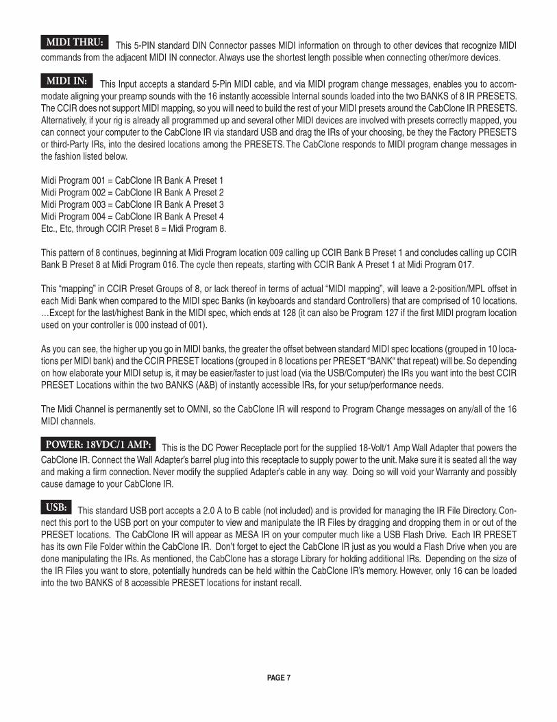
MIDI THRU: This 5-PIN standard DIN Connector passes MIDI information on through to other devices that recognize MIDI commands from the adjacent MIDI IN connector. Always use the shortest length possible when connecting other/more devices.
MIDI IN: This Input accepts a standard 5-Pin MIDI cable, and via MIDI program change messages, enables you to accom-modate aligning your preamp sounds with the 16 instantly accessible Internal sounds loaded into the two BANKS of 8 IR PRESETS. The CCIR does not support MIDI mapping, so you will need to build the rest of your MIDI presets around the CabClone IR PRESETS. Alternatively, if your rig is already all programmed up and several other MIDI devices are involved with presets correctly mapped, you can connect your computer to the CabClone IR via standard USB and drag the IRs of your choosing, be they the Factory PRESETS or third-Party IRs, into the desired locations among the PRESETS. The CabClone responds to MIDI program change messages in the fashion listed below.
Midi Program 001 = CabClone IR Bank A Preset 1 Midi Program 002 = CabClone IR Bank A Preset 2 Midi Program 003 = CabClone IR Bank A Preset 3Midi Program 004 = CabClone IR Bank A Preset 4Etc., Etc, through CCIR Preset 8 = Midi Program 8.
This pattern of 8 continues, beginning at Midi Program location 009 calling up CCIR Bank B Preset 1 and concludes calling up CCIR Bank B Preset 8 at Midi Program 016. The cycle then repeats, starting with CCIR Bank A Preset 1 at Midi Program 017.
This “mapping” in CCIR Preset Groups of 8, or lack thereof in terms of actual “MIDI mapping”, will leave a 2-position/MPL offset in each Midi Bank when compared to the MIDI spec Banks (in keyboards and standard Controllers) that are comprised of 10 locations. …Except for the last/highest Bank in the MIDI spec, which ends at 128 (it can also be Program 127 if the first MIDI program location used on your controller is 000 instead of 001).
As you can see, the higher up you go in MIDI banks, the greater the offset between standard MIDI spec locations (grouped in 10 loca-tions per MIDI bank) and the CCIR PRESET locations (grouped in 8 locations per PRESET “BANK“ that repeat) will be. So depending on how elaborate your MIDI setup is, it may be easier/faster to just load (via the USB/Computer) the IRs you want into the best CCIR PRESET Locations within the two BANKS (A&B) of instantly accessible IRs, for your setup/performance needs.
The Midi Channel is permanently set to OMNI, so the CabClone IR will respond to Program Change messages on any/all of the 16 MIDI channels.
POWER: 18VDC/1 AMP: This is the DC Power Receptacle port for the supplied 18-Volt/1 Amp Wall Adapter that powers the CabClone IR. Connect the Wall Adapter’s barrel plug into this receptacle to supply power to the unit. Make sure it is seated all the way and making a firm connection. Never modify the supplied Adapter’s cable in any way. Doing so will void your Warranty and possibly cause damage to your CabClone IR.
USB: This standard USB port accepts a 2.0 A to B cable (not included) and is provided for managing the IR File Directory. Con-nect this port to the USB port on your computer to view and manipulate the IR Files by dragging and dropping them in or out of the PRESET locations. The CabClone IR will appear as MESA IR on your computer much like a USB Flash Drive. Each IR PRESET has its own File Folder within the CabClone IR. Don’t forget to eject the CabClone IR just as you would a Flash Drive when you are done manipulating the IRs. As mentioned, the CabClone has a storage Library for holding additional IRs. Depending on the size of the IR Files you want to store, potentially hundreds can be held within the CabClone IR’s memory. However, only 16 can be loaded into the two BANKS of 8 accessible PRESET locations for instant recall.
PAGE 7

LIFT / GROUND: A mini toggle Ground Float switch is provided for the DI Output, which can lift the circuit Ground (Pin 1) from the chassis Ground. This Ground float switch can be helpful in eliminating ground loops caused by different references to Ground between consoles and the CabClone IR’s circuitry. Always start with the unit set to the GROUND (toggle down) position when con-necting the unit to a console. If you experience noise in the form of hum or buzz, you can try the LIFT (toggle up) position to see if perhaps the noise you are experiencing is caused from a different ground reference between the console and the CabClone IR. The switch does not always cure the noise problems associated with these differences in Ground, but it is very often effective and a welcomed feature when your anxious to get rolling in the studio or do a timely sound check at a gig.
180 / PHASE: Like the GROUND / LIFT feature above, the DI Output also has a Phase switch. This PHASE Reversal switch is a common and useful feature in the Pro Audio world, and allows you to flip the phase 180 degrees and get a much closer relation-ship to “in phase” when things are obviously out. This can come in handy not only when recording with an ensemble, but also when combining tracks of overdubbed parts that may have been recorded with very different amplifiers, cabinets or even instruments than that which you are attempting to blend. It also is invaluable should you want to combine amplifiers for a blended sound. This is even more true if the sounds are very different in gain structure, like say a clean sound with one amp and an overdriven sound in a different amp or even different Channel or Mode in the same amp. Very often different channels in an amp flip the phases depending on gain staging. Regardless of the application, the PHASE REVERSE switch is a great feature most professional pieces include. As with the GROUND switch, we suggest you start in the (toggle down) PHASE Normal position and try the 180 (toggle up) position if you notice the sound being strange or unusually dry, harsh or brittle and/or the low end lacking or unusually rolled off. Often times this is caused by an out of alignment phase relationship with other instruments.
DI OUTPUT: The standard male XLR provides the main feed to a console, interface or any other destination your IRs need to feed. The sound here will always be that of one of 16 PRESETS in the two BANKS, be they Factory IRs or others you might have dragged and dropped into one of the PRESET locations. The volume level at this balanced output is controlled by the Top Panel’s OUTPUT Level control. Being a balanced output, and therefore resistant to top end roll off due to capacitance, reasonably long cable lengths may be used when interfacing to your destination, say up to 50 or 60 feet, without much if any signal degradation. Brightness and top end cut/forwardness can be added or reduced with the Top Panel PRESENCE control.
NOTE: It is always good practice to start any session or sound check, Recording and Live, with the OUTPUT Level Control on the CCIR’s Top Panel, as well as the input level fader or control on the console/interface, zeroed out before connecting the XLR cable to the CabClone IR’s OUTPUT. This safeguard will prevent accidental overload of the console Input, Monitors, Headphones and ears as well as possible component damage in other parts of the system. Everyone involved in the production, as well as your own ears, will appreciate the thoughtfulness.
LINE OUT (DRY): A mono ¼” phono Output is provided here for the unprocessed signal direct from the INPUT jacks, whether it be the signal from your amplifier’s SPEAKER OUTPUT connected to the FROM AMP SPKR OUT Input, or the sound of a preamp fed into the LINE Input. The processed IRs are fed ONLY to the DI OUTPUT and the HEADPHONES ¼” stereo Output. The signal strength of the LINE OUT (DRY) Output is determined by the Top Panel’s INPUT Level Control (as well as whatever Output Controls affect signal strength of the source sent to the CCIR’s INPUTS). The PRESENCE and OUTPUT Level controls have no effect on the signal present at the LINE OUT (DRY) Output.
HEADPHONES: The standard ¼” stereo phono jack provides the Output for Headphones. This allows the CabClone IR to not only be easy to control in private between live performance as well as Recording passes, but also a great tool for “silent” consider-ate practicing when you need an inspiring sound but don’t want to disturb those around you. Like the balanced XLR DI OUTPUT, the volume level and brightness/character at the HEADPHONES Output is also determined by the Top Panel’s OUTPUT Level and PRESENCE controls.
PAGE 8

TOP PANEL CONTROLS
CLIP LEDs: These three LED lights indicate the signal level at the LINE and FROM AMP SPKR OUT INPUTS. The Green, Yel-low, Red increment LEDs indicate just what you’d think: Green indicates signal, but lower (workable but not ideal) signal level. Yellow shows an optimum (nominal/perfect) level signal strength and Red indicates an overly high/too hot, you are either about to, or are, clipping the Input, signal level. Whenever possible it is best to have the Yellow LED illuminated fully but not to light the Red LED. A weak Input signal level may generate excess noise and too high of an Input signal strength will cause clipping which may produce an unwanted (and unpleasant sounding) clip at the processor’s input stage.
INPUT LEVEL: This control determines the input signal strength to the processor. It also determines the signal strength/Output Level that appears at the LINE OUT (DRY) ¼” Output. Set your amplifier’s (or preamplifier’s) Master Volume (if applicable) to an adequate but not overly loud/high setting. Use the adjacent CLIP LEDs to help you adjust the INPUT control so that you achieve an optimum input signal strength that illuminates the Yellow LED with most all of your dynamic range applied without lighting the Red LED. This scenario should provide a solid signal level with which to trigger the IRs/Cabinet Simulations and deliver great performance.
PRESENCE: This control provides tonal options by providing an easy way to brighten or roll off of the high frequencies/upper harmonics. Use the PRESENCE to alter the response of the attack characteristics in the different types of Cabinet Simulations. Compensate more easily for differing rooms in Live situations. or adjust the sound for more accuracy in how your parts sound, feel and blend in recording environments. The PRESENCE control is flat when set to 12 o’clock, so this would be the best starting point. This real time adjustability has the distinct benefit of being instant, easy to use and extremely effective at sculpting the most important parts of the sound for both clean and overdrive styles.
OUTPUT LEVEL: This control determines the signal level at the balanced XLR DI OUTPUT and the HEADPHONES ¼” Stereo jack. It does NOT control the signal level at the TO SPKR Output, which is controlled by your amp’s Master Volume, or the LINE OUT (DRY) Output, which derives its level from the INPUT control on the Top Panel of the CabClone IR.
Note that overloading the Input stage of your console or other destination device will result in unpleasant “digital” sounding clipping and should be avoided. Reduce the level of the OUTPUT control and/or the Input Trim on the console until there is sufficient level for an optimum signal to noise ratio, yet no clipping is detected. It is best to start sessions with the OUTPUT set to zero/off, then set the destination’s Input Trim at unity and then increase the signal level with the CCIR’s OUTPUT control such that the signal remains clean and does not clip, even on your most dynamic passages (hardest strikes of the strings).
If you plan to monitor your playing through Headphones from the CabClone IR HEADPHONES Output directly and not your console, you will need to set the listening level of the Headphones first with the OUTPUT control, then set the console Input Trim accordingly, not the other way around. As mentioned earlier, the OUTPUT control is responsible for both the DI OUPTUT level and the HEAD-PHONES Output levels simultaneously.
CAB SELECT ROTARY & BANK SELECT SWITCH: This 8-position rotary selector and 8 corresponding LEDs, along with the two position BANK SELECT mini toggle, allow you to sequence through the 8 IRs in each BANK. Notice that the color of the LEDs changes from green in BANK A to red when you select BANK B. This informs you that you are on the lower BANK of 8 IRs (STUDIO versions as loaded from Factory).
IRs can be loaded into any order you choose, but from the Factory, the CabClone IR ships with the identical biggest closed-back cabinets loaded in the first five positions and the open-back Cabinets in the following three positions of both BANKS. This was done to place the biggest sounding/most popular cabinets first, and the smaller, less popular, style-specific cabinets last. You may rearrange or replace any of them by connecting the USB port to your computer and placing the IR Files in your desired locations, one through eight.
PAGE 9

ORGANIZING AND LOADING IR’s:
To load files into the CCIR, connect the device to a computer (Mac or Windows) using a standard USB 2.0 Cable. When connected and recognized by the computer, the CCIR appears on your computer file system as a Flash Drive named MESA IR. The CabClone IR uses the standard mass storage protocol, so in most cases, no specific driver is required to read the Files. In Windows, if a driver is needed it will automatically install when connected the first time. Allow this process to finish (which takes approximately one minute) before continuing.
While the unit is connected to a computer:• The 8 Preset LEDs will remain illuminated
• The audio is muted at all Outputs
• The BANK toggle switch and PRESET rotary are rendered inoperative
• MIDI commands will be ignored and not be sent to the MIDI THRU.
Within the MESA IR Flash Drive will be three folders: Bank A, Bank B, and Cab Library. Within each Bank Folder will be Eight Sufold-ers, labeled File 1 through File 8. These folders correspond to the 8 IR Presets that are accessible with the CAB SELECT rotary and Bank A/B Switch.
Only one IR file should be placed in each file folder. If more than one file is placed within a folder, or if no file at all is placed in a file folder, the device will ignore that folder location, resulting in silence when selecting the corresponding CCIR PRESET location. The corresponding Preset LED will also flash.
The Cab Library folder can be used as a storage folder for either new MESA, or 3rd party IRs. Depending on the IR file sizes, the folder can hold several hundred IRs. This allows for easy drag and drop placement of any stored IR file into the IR Preset locations.
After dragging and dropping IRs to the folders, just like you would a portable flash drive, ejecting the USB device through the Eject function of Windows or Mac OS is required. As with any computer and USB storage medium, disconnecting the CCIR without this procedure may result in lost data.
Note: To ensure fast IR switching especially when addressing the unit via MIDI, the 16 IR files in the “File” folders are buffered to an internal high speed library. This takes place when the device is ejected. When the 16 files are new, the process can take up to 20 sec-onds. During that time, the input LEDs blink and progress is indicated on the Preset LEDs. Allow this process to finish before continuing.
That wraps it up for the rundown of Features and Controls. We hope the CabClone IR provides you with a useful and convenient tool for both your recording and live DI needs and helps inspire you in your musical endeavors.
From all of us at the MESA/Boogie Ltd, Thank You for trusting us with your Tone. If we can assist you in any way, now or in the future, don’t hesitate to reach out by email or phone as we’re here to help you sound your very best every time you play. Enjoy!
PAGE 10

Example Live and Studio Connection Diagrams:
PAGE 11
INTERNAL LOAD
OHMS 150W RMS
18VDC1 AMPINPUTS
FROM AMPSPKR OUT
TO SPKR
LINE OUT (DRY)LINE / INST
MIDI THRU MIDI IN HEADPHONESUSB DI OUTPUTPHASE
(OPTIONAL)
GROUND
LIFT
180º
OUTPUT
WARNING:Read User Manual Before Use.
Do Not Expose To Rain Or Moisture.
CAUTION:Do Not Set Amp Output To Max -
Damage May Occur.®
MADE IN PETALUMA, CALIFORNIA, USA WITH THE WORLD’S FINEST MATERIALS
MIXER
RECORDING STUDIO
8 OHM OUT
OUT OF MIXERTO MONITORS
8 OHM IN
MIXER CHANNEL IN
(SHOWN WITH 8 OHM CABCLONE™ IR)
STUDIO MONITORS
GUITAR AMP
GUITAR CABINET (OPTIONAL)

PAGE 12
INTERNAL LOAD
OHMS 150W RMS
18VDC1 AMPINPUTS
FROM AMPSPKR OUT
TO SPKR
LINE OUT (DRY)LINE / INST
MIDI THRU MIDI IN HEADPHONESUSB DI OUTPUTPHASE
(OPTIONAL)
GROUND
LIFT
180º
OUTPUT
WARNING:Read User Manual Before Use.
Do Not Expose To Rain Or Moisture.
CAUTION:Do Not Set Amp Output To Max -
Damage May Occur.®
MADE IN PETALUMA, CALIFORNIA, USA WITH THE WORLD’S FINEST MATERIALS
AUDIO INTERFACE
INPUT
PREAMP
GAINOUTPUT INPUTTREBLE MID BASS PRESENCE MASTER
SLAVE OUT
STUDIO MONITORS COMPUTER
GUITAR CABINET(REQUIRED WHEN USING
SLAVE OUT)
SLAVE OUT / LINE LEVEL
OR
GUITAR AMP
OUT OFMIXER TO MONITORS

PAGE 13
INTERNAL LOAD
OHMS 150W RMS
18VDC1 AMPINPUTS
FROM AMPSPKR OUT
TO SPKR
LINE OUT (DRY)LINE / INST
MIDI THRU MIDI IN HEADPHONESUSB DI OUTPUTPHASE
(OPTIONAL)
GROUND
LIFT
180º
OUTPUT
WARNING:Read User Manual Before Use.
Do Not Expose To Rain Or Moisture.
CAUTION:Do Not Set Amp Output To Max -
Damage May Occur.®
MADE IN PETALUMA, CALIFORNIA, USA WITH THE WORLD’S FINEST MATERIALS
AUDIO INTERFACE
INPUT
OUT OFMIXER TO
MONITORS
8 OHM OUT
8 OHM IN
STUDIO MONITORS COMPUTER
GUITAR CABINET(OPTIONAL)
GUITAR AMP
CONNECT TO DAW / RECORDING
(SHOWN WITH 8 OHM CABCLONE™ IR)
PAGE 14
INTERNAL LOAD
OHMS 150W RMS
18VDC1 AMPINPUTS
FROM AMPSPKR OUT
TO SPKR
LINE OUT (DRY)LINE / INST
MIDI THRU MIDI IN HEADPHONESUSB DI OUTPUTPHASE
(OPTIONAL)
GROUND
LIFT
180º
OUTPUT
WARNING:Read User Manual Before Use.
Do Not Expose To Rain Or Moisture.
CAUTION:Do Not Set Amp Output To Max -
Damage May Occur.®
MADE IN PETALUMA, CALIFORNIA, USA WITH THE WORLD’S FINEST MATERIALS
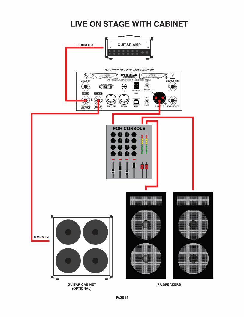
FOH CONSOLE
8 OHM OUT
8 OHM IN
GUITAR CABINET(OPTIONAL)
PA SPEAKERS
GUITAR AMP
LIVE ON STAGE WITH CABINET
(SHOWN WITH 8 OHM CABCLONE™ IR)

PAGE 15
INTERNAL LOAD
OHMS 150W RMS
18VDC1 AMPINPUTS
FROM AMPSPKR OUT
TO SPKR
LINE OUT (DRY)LINE / INST
MIDI THRU MIDI IN HEADPHONESUSB DI OUTPUTPHASE
(OPTIONAL)
GROUND
LIFT
180º
OUTPUT
WARNING:Read User Manual Before Use.
Do Not Expose To Rain Or Moisture.
CAUTION:Do Not Set Amp Output To Max -
Damage May Occur.®
MADE IN PETALUMA, CALIFORNIA, USA WITH THE WORLD’S FINEST MATERIALS
8 OHM OUT GUITAR AMP
HEADPHONES
SILENT WITH HEADPHONES
(SHOWN WITH 8 OHM CABCLONE™ IR)
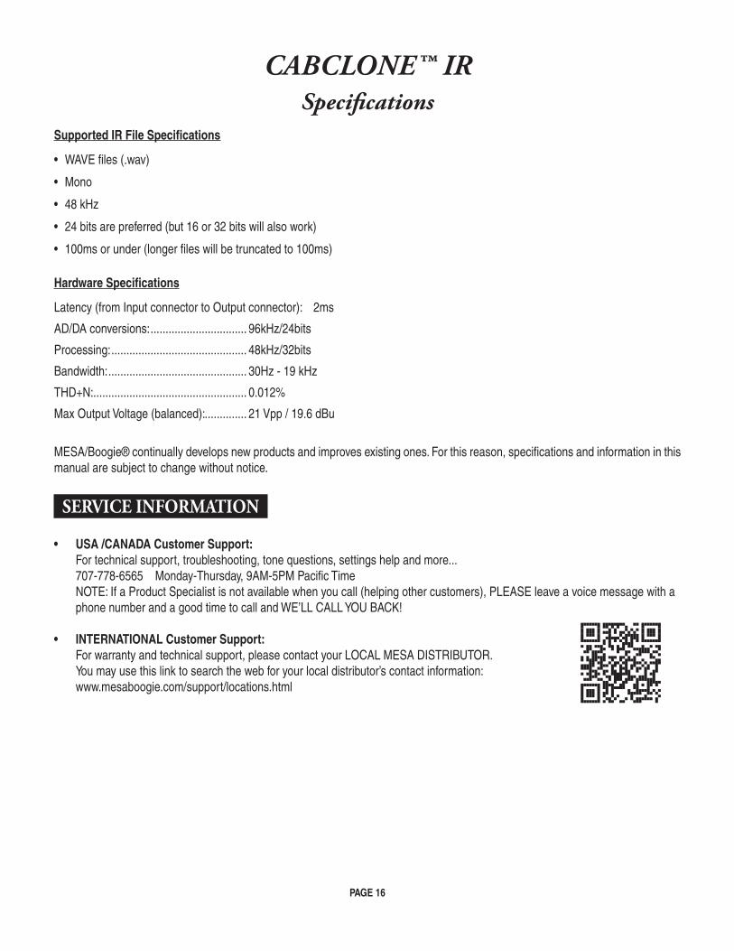
CABCLONE™ IRSpecifications
Supported IR File Specifications
• WAVE files (.wav)
• Mono
• 48 kHz
• 24 bits are preferred (but 16 or 32 bits will also work)
• 100ms or under (longer files will be truncated to 100ms)
Hardware Specifications
Latency (from Input connector to Output connector): 2ms
AD/DA conversions: ................................ 96kHz/24bits
Processing: ............................................. 48kHz/32bits
Bandwidth: .............................................. 30Hz - 19 kHz
THD+N: ................................................... 0.012%
Max Output Voltage (balanced): .............. 21 Vpp / 19.6 dBu
MESA/Boogie® continually develops new products and improves existing ones. For this reason, specifications and information in this manual are subject to change without notice.
SERVICE INFORMATION
• USA /CANADA Customer Support: For technical support, troubleshooting, tone questions, settings help and more... 707-778-6565 Monday-Thursday, 9AM-5PM Pacific Time NOTE: If a Product Specialist is not available when you call (helping other customers), PLEASE leave a voice message with a phone number and a good time to call and WE’LL CALL YOU BACK!
• INTERNATIONAL Customer Support: For warranty and technical support, please contact your LOCAL MESA DISTRIBUTOR. You may use this link to search the web for your local distributor’s contact information: www.mesaboogie.com/support/locations.html
PAGE 16


NOTE: This equipment has been tested and found to comply with the limits for a Class A digital device, pursuant to part 15 of the FCC Rules. These limits are designed to provide reasonable protection against harmful interference when the equipment is operated in a commercial environment. This equipment generates, uses and can radiate radio frequency energy and, if not installed and used in accordance with the instruction manual, may cause harmful interference to radio communications. Operation of this equipment in a residential area is likely to cause harmful interference in which case the user will be required to correct the interference at his own expense.

19/12/31