Overview: The Map Window - Max Online · of the Map window. The tools and visualization controls...
33
UG-MPW-1 © Copyright ThinkSpace Inc., 1998, Version 1 Overview: The Map Window The MFworks Map window is a powerful facility for the visualization and manipulation of map layer data. It permits you to view each data point individually or in context with all the other data points. The Map window is the focal point for all the other windows associated with the map layer: the Legend window, the Information window, the Comment window, and the Layout window. Actions performed in an associated window can affect the appearance and characteristics of the Map window and vice versa. The Map window comes with a set of tools and controls that give you the ability to mark, measure, view, and alter the appearance of the map layer and change its underlying data. Title Bar Drawing Value Polygon Tool Pencil Tool Selection Tool Map Name Numeric Magnifying Glass Line Tool Paint Can Tool Zoom Ratio Zoom Out Zoom In Redraw/Stop Button Drawing Colour Map Display Horizontal Scroll Bar Vertical Scroll Bar Overview: The Map Window The Map Menu Map Window Tools and Controls Map Drawing Tools Clipboard Commands Undoing Edits
-
Upload
hoangduong -
Category
Documents
-
view
218 -
download
1
Transcript of Overview: The Map Window - Max Online · of the Map window. The tools and visualization controls...

d
is the
he Map to ange
Overview: The Map WindowThe MFworks Map window is a powerful facility for the visualization anmanipulation of map layer data. It permits you to view each data point individually or in context with all the other data points. The Map windowthe focal point for all the other windows associated with the map layer:Legend window, the Information window, the Comment window, and the Layout window. Actions performed in an associated window can affect tappearance and characteristics of the Map window and vice versa. Thewindow comes with a set of tools and controls that give you the ability mark, measure, view, and alter the appearance of the map layer and chits underlying data.
Title Bar
Drawing Value
Polygon Tool
Pencil Tool
Selection Tool
Map NameNumeric Magnifying Glass
Line Tool
Paint Can Tool
Zoom Ratio
Zoom Out
Zoom In
Redraw/StopButton
Drawing Colour
Map Display Horizontal Scroll Bar
VerticalScroll Bar
Overview: The Map WindowThe Map MenuMap Window Tools and ControlsMap Drawing ToolsClipboard CommandsUndoing Edits
UG-MPW-1© Copyright ThinkSpace Inc., 1998, Version 1

e top the
e
ve
he Map pen
for om
e top inter
The name of the map layer appears on the left side of the title bar on thof the Map window. The tools and visualization controls appear aroundoutside of the Map window. The scroll bars on the right-hand side andbottom of the window permit you to scroll the map if it is larger than theMap window's field of view. The Map window can be moved around thdesktop and resized.
The Map MenuThe Map window has its own menu in the menu bar when it is the actiwindow. The Map menu allows you to show or hide several features of tMap window. It contains zoom commands which can be used when the window tools are hidden. It permits you to add active map layers to the oproject. It has options to switch the rulers to display a user defined coordinate system and define or update a coordinate system. And, it has an option that allows you to dither the Map window colours to compensatemonitors with limited colour display capabilities. The settings chosen frthe Map menu apply only to the active Map window.
Rulers Rulers are graduated scales which, when selected, are displayed on thand left-hand sides of the map. The rulers can be set to display the poposition by row and column number, distance from the point (0,0), or a user defined coordinate system. Rulers display the position of the pointer as it
UG-MPW-2© Copyright ThinkSpace Inc., 1998, Version 1

f
e
the acker t to
moves over the map by two sliding triangles. The triangles track the horizontal and vertical movement of the pointer relative to the rulers.
Use the Show Rulers or Hide Rulers options from the Map menu to turn the rulers on or off.
Tracker Use the Tracker option from the Map menu to turn the numeric display othe pointer tracker on or off.
The tracker displays four different numeric items along the bottom of thmap window, below the scroll bar. The first two numbers, beside the vertical and horizontal arrows, are the coordinates of the cell over whichpointer is passing. When the rulers are set to display in distances, the trgives position as distance from the point (0,0). When the rulers are se
UG-MPW-3© Copyright ThinkSpace Inc., 1998, Version 1

rner e is
ect. of
r top cell the
display in a user defined coordinate system, the tracker will give position in either Latitude and Longitude, or in UTM metres.
The number beside the diagonal arrow is the pointer’s distance from aselected cell. If more than one cell is selected, then the top left-hand cocell of the selection is the cell from which distance is measured. Distancgiven in number of cell units, the number of data units (i.e., mm, cm, m, or km), or the number of real world units depending on which ruler you selDistance is measured from the centre of the specified cell to the centrethe cell over which the pointer is passing.
The next pair of numbers are related to the azimuth of the map. The first number is the bearing in degrees from the centre of the selected cell, oleft-hand corner cell if more than one cell is selected, to the centre of theover which the pointer is passing. The second number, in brackets, is
222
446
UG-MPW-4© Copyright ThinkSpace Inc., 1998, Version 1

ified
g
next
ly to
back bearing from the cell over which the pointer is passing to the speccell.
Tools The Tools menu option allows you to turn the tool box on or off. Turninthe tool box off affords a wider display area.
To maximize the size of the Map window, turn off the tools, rulers, andtracker and expand the Map window to fill the entire screen adjust the magnification of the view using the Zoom controls in the Map menu to set the map size to fit in the full screen window. Choose the tool to be used on the map before hiding the tools, otherwise Show Tools will have to be used again to select the tool.
Add to project To add a map layer reference that has been removed from a project map layer reference list back to the list, use the Add to Project option in the Map menu. When a map is opened or created, it is added automatical
N
Bearing Back Bearing
Show Tools Hide Tools
UG-MPW-5© Copyright ThinkSpace Inc., 1998, Version 1

d in a
ins data ap,
or the
ap t
and
the reference list of the open project. To make the addition permanent,save the project before closing it.
If a map layer has not been added to the open project, it cannot be usescript. Attempting to do so will cause the following error message to bedisplayed:
Map Window Tools and ControlsThe tool box located in the top left-hand corner of the Map window contathe tools and controls necessary to select portions of the map, view thevalues of selected cells, change the value of cells by “drawing” on a malter the magnification of the Map window, and redraw the window.
The tool box can be hidden to make a greater area of screen available fmap display. Use the Tools option in the Map menu to do this.
Selection tool The selection tool is used to select a cell, or rectangle of cells, in the Mwindow. Clicking on a single cell with the selection tool will highlight thacell with a marquee. When a single cell is selected, the drawing colour
Numeric MagnifyingGlass
Line Tool
Paint Can Tool
Zoom In
Redraw Button
Selection Tool
Pencil Tool
PolygonTool
Zoom Ratio
Zoom Out
UG-MPW-6© Copyright ThinkSpace Inc., 1998, Version 1

ct
the , use
ed to
cells t. ce.
sing
value in the bottom left-hand corner of the Map window change to reflethe value and colour of the cell.
To select more than one cell, click and drag a marquee to encompasscells to be specified. When more than one cell is selected, the drawingcolour and value in the bottom left-hand corner of the Map window willremain unchanged. To change a selection after it has initially been setshift-click to increase or decrease the marquee to the pointer position.
The selection tool can be used in conjunction with the rulers and the trackers to measure distance and direction from specified cells. It can also be usselect portions of the map for editing.
The selection tool can be used to direct the zoom commands. Selectedalways remain in the centre of the Map window when zooming in or ouThis is useful for viewing a map and then focusing in on a particular plaSimply click on a cell in the centre of the area of interest and zoom in uthe zoom controls from the tool box or the zoom commands from the Map menu.
UG-MPW-7© Copyright ThinkSpace Inc., 1998, Version 1

he
also
. To p
and
the this
The selection tool can be used with the redraw button to redraw only tarea within the selection marquee.
The selection tool can be used to set the drawing colour and value it isused to specify an area to be placed in the Clipboard , or to specify the position on the map where cells from the Clipboard are to be pasted.
Numericmagnifying
glass
The numeric magnifying glass is a tool to view the actual values in cellsuse the magnifying glass, click on the magnifying glass button at the toright-hand corner of the tool box. Move the pointer over the map area the pointer will change from an arrow to a magnifying glass.
Move the pointer so that the cell, or cells, of interest are centred undermagnifying glass, then press and hold down the mouse button. Doing
UG-MPW-8© Copyright ThinkSpace Inc., 1998, Version 1

the
ove l. If l en
e
s.
brings up a 5 cell by 5 cell matrix displaying the values and colours of cells that are centred under the pointer.
Move the pointer with the mouse button depressed and the matrix will mwith it and change to reflect the new values surrounding the centre celthe pointer is moved beyond the edge of the Map window, the map wilscroll until the last row or column is reached. The matrix is not visible whthe map is scrolling.
Drawing tools The drawing tools are grouped together below the selection tool and thmagnifying glass. Please refer to Map Drawing Tools, for a complete discussion of the drawing tools.
There are four drawing tools:
The Pencil toolThe Pencil tool is used for marking one cell at a time or for freehand drawing.
The Line toolThe Line tool is used for drawing straight segments between two point
UG-MPW-9© Copyright ThinkSpace Inc., 1998, Version 1

t line illed
nt
p n o
in g
The Polygon toolThe Polygon tool is used for drawing a sequence of connected straighsegments (open polygons) between two points or for creating closed, fpolygons.
The Paint Can toolThe Paint Can tool is used for filling areas that contain identical adjacevalues.
Zoom controls The zoom controls affect the magnification at which the map in the Mawindow is viewed. The zoom controls set the Map window magnificatioas a cell-to-pixel ratio. The Map window zoom can be adjusted from twplaces: the tool box, and the Map menu.
The Map window magnification can be set in two ways using the zoomcontrols in the tool box. The first is by clicking on the zoom out or zoombuttons. Pressing zoom out reduces the magnification by 50% pressinzoom in increases the magnification by 200%. The change in zoom is reflected automatically on the zoom ratio button display.
Zoom In
Zoom Ratio
Zoom Out
UG-MPW-10© Copyright ThinkSpace Inc., 1998, Version 1

to
atio ere by by els can
The second way to adjust the magnification using the zoom controls isclick and hold the zoom ratio button. Clicking on this button causes thezoom ratio drop-down list to be displayed.
To adjust the magnification select a zoom ratio from the menu. A zoom rof 2:1 reduces magnification by 50% from a 1:1 ratio. In other words, thare two cells in each axis direction (four cells all together) representedeach pixel on the screen. A zoom ratio of 1:2 increases magnification 200% from a 1:1 ratio. In other words, there is one cell for every two pixin each axis direction (four pixels per cell) on the screen. Magnification go from a minimum of 32:1 to a maximum of 1:32.
These same capabilities are available from the Map menu. Use the zoom commands in the Map menu when the tool box is hidden.
UG-MPW-11© Copyright ThinkSpace Inc., 1998, Version 1

ed
, s. The and
the ed,
and lour
ing,
Instead of buttons, the Map menu has Zoom out and Zoom in commands, and a Zoom ratio submenu. Magnification can be set in increments bason powers of 2 from 32:1 to 1:32.
Note: drawing tools do not function below a ratio of 1:1.
Redraw tool Redraw is used when the Map window, or a portion of the Map windowneeds to be redrawn. The ESC key is used to halt the redrawing procesonly time this button is likely to be used is when the map is very large is being viewed at a high zoom ratio (e.g., 32:1) or when only a small partof the map is to be viewed.
To view only a small portion of the map, click on the stop button to halt redrawing process, use the selection tool to specify the area to be viewthen click on redraw button only the selected area will redraw.
Drawing colourand value
The current drawing colour and value are displayed in the bottom left-hcorner of the Map window. When a map layer is opened, the drawing coand value fields in the bottom left-hand corner of the Map window will reflect the colour and value of the first legend entry.
Map Drawing ToolsThe Map window tool box comes equipped with four different drawing tools that can be used to modify a map by marking, tracing, erasing, fill
UG-MPW-12© Copyright ThinkSpace Inc., 1998, Version 1
and
s
.
st be
the
set. ouse d or t,
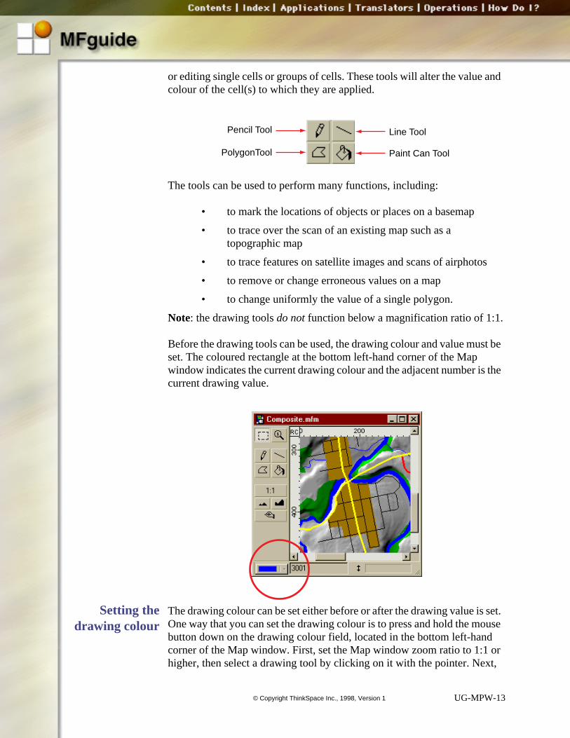
or editing single cells or groups of cells. These tools will alter the value colour of the cell(s) to which they are applied.
The tools can be used to perform many functions, including:
• to mark the locations of objects or places on a basemap
• to trace over the scan of an existing map such as a topographic map
• to trace features on satellite images and scans of airphoto
• to remove or change erroneous values on a map
• to change uniformly the value of a single polygon.
Note: the drawing tools do not function below a magnification ratio of 1:1
Before the drawing tools can be used, the drawing colour and value muset. The coloured rectangle at the bottom left-hand corner of the Map window indicates the current drawing colour and the adjacent number iscurrent drawing value.
Setting thedrawing colour
The drawing colour can be set either before or after the drawing value isOne way that you can set the drawing colour is to press and hold the mbutton down on the drawing colour field, located in the bottom left-hancorner of the Map window. First, set the Map window zoom ratio to 1:1higher, then select a drawing tool by clicking on it with the pointer. Nex
Line Tool
Paint Can Tool
Pencil Tool
PolygonTool
UG-MPW-13© Copyright ThinkSpace Inc., 1998, Version 1

rop-
press and hold on the drawing colour field to display the colour palette ddown list. Choose a colour from the menu, or select Other to open the Colour Picker dialog box.
UG-MPW-14© Copyright ThinkSpace Inc., 1998, Version 1

mple, 15.
If the Other option is selected, the Colour Picker dialog box will open in either RGB, CMY , or HSL mode, depending on what colour model wasused last (RGB is the default).
If you are most comfortable choosing colours from the standard Windows System Colours, click on the System button to set the drawing colour. Toswitch between colour models, click on the Model drop-down list and selectthe colour model to be used.
Use the Colour Picker to select the colour (refer to the Legend Window document), then click on the OK button. By default, the drawing value willbe set to the last value found in the map layer data set plus one. For exaif the last value in the data set is 14, then the drawing value will be set to
UG-MPW-15© Copyright ThinkSpace Inc., 1998, Version 1

r. en
data
ing
Refer to Setting the drawing value, below, to find out how to change thisvalue.
Setting thedrawing value
The drawing value can be set before or after setting the drawing colouSelect a drawing tool, then click on the value field with the pointer. Whthe existing value is highlighted, type in the new drawing value.
If the drawing colour is not set, MFworks will assign a random colour automatically. If a value is entered that already exists in the map layer set, then the colour for that value will be used automatically.
Using theselection tool to
draw withexisting colours
and values
To draw with a colour and value that already exists in the map, use theselection tool to click on a cell that is the required colour and value. Do
Hilight the drawing value andtype in a new value
UG-MPW-16© Copyright ThinkSpace Inc., 1998, Version 1

the
t
and
ly try is
this will automatically set the drawing colour and value display to reflect colour and value of the selected cell.
With the drawing colour and value set, click on a drawing tool and stardrawing.
Using theLegend window
to set existingcolours and
values
Another way to set the drawing colour and value to an existing colour value is to make the Legend window the active window, then click on the legend entry with the required colour and value. To use this method onone legend entry can be selected at a time. If more than one legend en
Click on a cell to copy its drawingcolour and value
UG-MPW-17© Copyright ThinkSpace Inc., 1998, Version 1

our
ing
the set ged nd
uch . To d
cell
highlighted, the first legend entry selected will become the drawing coland value.
The drawing tool can be selected either before or after setting the drawcolour and value if the colour and value are set from the Legend window.
Pencil tool The pencil tool is a freehand drawing tool that can be used to change colour and value of a single cell or group of cells. To mark a single cell,the drawing colour and value, then click on the cell in the map to be chanwith the pencil tool. The specified cell will be assigned the new colour avalue.
The pencil tool is the ideal drawing tool for tracing complicated shapes sas rivers and rock outcrops where there are very few long, straight linesuse the pencil tool continuously, click at the start point of the outline anhold down the mouse button slowly drag the tool along the outline. Each
UG-MPW-18© Copyright ThinkSpace Inc., 1998, Version 1

d the
ow
ess
ng
that the tool passes over will be changed to the new colour and value anLegend window will be updated automatically to reflect the change.
If the pencil tool is dragged beyond the visible cell area, the Map windwill scroll.
To restrict the pencil tool to drawing vertical and horizontal lines only, prthe Shift key before clicking and dragging.
Hint : Set the mouse tracking (speed) to the slowest setting when tracicomplicated shapes. This will permit finer control of the pencil tool. To
UG-MPW-19© Copyright ThinkSpace Inc., 1998, Version 1

change the mouse tracking, open the Mouse Properties control panel in the Control Panels folder.
UG-MPW-20© Copyright ThinkSpace Inc., 1998, Version 1

gin.
t to til oint, utton.
d to d
Line tool The line tool is used to mark straight lines between two points. Set thedrawing colour and value, then click on the point where the line is to beThis point is called the anchor point.
Hold down the mouse button and drag the line out from the anchor pointhe end point. The line will move with the tool from the anchor point unthe mouse button is released. Carefully position the tool over the end pcheck to be sure that the line is positioned correctly, then release the b
To constrain the angle at which the line is drawn, hold down the Shift key while drawing. This will limit the line to be drawn to 45° increments fromthe vertical (i.e., 0°, 45°, 90°, 135°, etc.).
If the line is dragged beyond the visible cell area, the Map window willscroll.
Polygon tool The polygon tool can be used in two ways: to draw an open polygon, andraw a closed, filled polygon. In both cases, set the drawing colour anvalue, then start drawing.
UG-MPW-21© Copyright ThinkSpace Inc., 1998, Version 1

ex e to
ade
be
45°
t and a new . A
lar nd
Using the Polygon Tool to Draw Open PolygonsThe polygon tool works better than the line tool for tracing fairly comploutlines because it allows continuous drawing. A new line does not havbe started for each line segment.
The polygon tool is ideal for tracing the course of a winding road or themeanders and turns of a river network — any continuous path that is mup of multiple segments.
As with the line tool, the angle that each line segment is drawn at can constrained by holding down the Shift key while dragging out the line segment from the anchor point. This limits the segment to be drawn toincrements from the vertical (i.e., 0°, 45°, 90°, 135°, etc.).
To use the polygon tool, click and release the mouse button at the starend points of each line segment. Click each time a segment ends and anchor point will be placed from which the next segment can be drawnline will track from the new anchor point and follow the pointer until thenext point is placed by clicking.
To complete the open polygon, double click as the last anchor point isplaced.
Using the Polygon Tool to Draw Closed PolygonsThe polygon tool can also be used to outline and fill regular and irregushaped areas. To trace the outline of the polygon use the same click amove technique outlined above.
1
23
45
67
8
Click Hereto Start
Double Clickto Close
UG-MPW-22© Copyright ThinkSpace Inc., 1998, Version 1

st ls of int. fill
area ct lls his
n
y or the cell he
the to
To draw a closed polygon, click on the first point so that the first and lapoint are the same. When the polygon tool is moved to within three celthe first anchor point the line segment will automatically “snap” to the poTo close the polygon, click the mouse button. The closed polygon will automatically with the specified drawing colour and value.
Paint can tool This tool is used to change the colour and value of an existing uniform of cells with identical values. The cells to be changed must be in contawith each other either horizontally or vertically. Diagonally adjacent ceof the same value will not be affected by applying the paint can tool. Tprocess is known as filling . A fill can be applied to an object that has beeoutlined with the pencil tool, the line tool, or the polygon tool.
The paint can tool works by checking the cell values that are horizontallvertically adjacent to the first cell that was clicked on. If the values aresame, the cell will be assigned the new value; if they are different, the value will remain unchanged. Picture a flood of paint spilling out from tfirst cell into all the horizontally and vertically connected cells with the same value as the first cell. Each cell with a value that is different fromfirst cell repels the paint and remains unchanged. The paint continues
12
3
4
5
Click to Close
UG-MPW-23© Copyright ThinkSpace Inc., 1998, Version 1

lls
t nd
flow until no more horizontally and vertically connected same-value ceare encountered.
To use the paint can tool, position the very end of the drop of paint thaappears to be pouring from the paint can over the first cell to be filled aclick the mouse button.
12
3
Apply Paint CanTool to this cell
New colour andvalue do not spillover intodiagonally adjacensimilar cells
12
Click on cell to be filled with this part
of the tool
UG-MPW-24© Copyright ThinkSpace Inc., 1998, Version 1

is
iew
e
layer yer
The fill operation can take a long time to perform, especially if the maplarge. The routine checks the whole map for “leaks” where the paint might spill out into adjacent cells.
Use Shift-click with the paint can tool to constrain the fill to the current window view. First make sure that there are no cells outside the current vthat should be included in the fill, then hold down the Shift key and click the mouse button on the cell where the fill is to start.
Only similar horizontally and vertically adjacent cells within the visible Map window will be filled. This technique also allows you to employ thedge of the Map window as a “fence” to block the flow of paint.
Clipboard CommandsMFworks supports all the standard Clipboard editing commands. You canCut, Copy, and Paste to and from the Clipboard facility. Cut, copy, and paste can be performed either on the same map layer or from one mapto another. Individual map layers can be edited, sections of one map la
UG-MPW-25© Copyright ThinkSpace Inc., 1998, Version 1

en
ct
er of
the ap tre of igin.
n it. that
can be pasted onto another, a new map layer can be created from a subscene of an existing map layer or a mosaic of several map layers together.
To perform Clipboard commands on a map, the Map window must be opand active.
Selection tool Before using the Cut and Copy commands, use the selection tool to selethe cell or cells to be acted on.
Use the pointer to choose the selection tool from the top left-hand cornthe Map window tool box.
The selection tool can be used to select a cell or a rectangle of cells frommap in the Map window. When the selection tool is passed over the mviewing area it becomes a cross-hair the cell beneath the dot in the centhe cross-hair defines the position of the selection tool relative to the orIts position can be determined using the rulers and tracker.
To select a single cell, centre the selection tool over the cell and click oTo select a range of cells, click on one of the corners of the rectangle
UG-MPW-26© Copyright ThinkSpace Inc., 1998, Version 1

rag area.
king new
ill ssing
tion
from l e
will define the area to be selected, hold down the mouse button, then dthe marquee from the anchor point to encompass the desired selection
Release the mouse button and the marquee will remain in position. Clicanywhere on the map will de-select the specified area and will cause acell or cell area to be selected.
To resize or reshape the marquee, hold down the Shift key and click near the corner of the marquee to be adjusted. The corner of the marquee wsnap to the specified position. Resize and reshape the marquee by preShift-click and holding down the mouse button. To define the new selecreposition the mouse then release the mouse button.
Cutting To cut, use the selection marquee to define the cell or cell area to be cutthe map, then choose Cut from the Edit menu. The selected cell or cells wilbe placed in the Clipboard and their values and colours in the map will b
UG-MPW-27© Copyright ThinkSpace Inc., 1998, Version 1
ed
opied
d at the
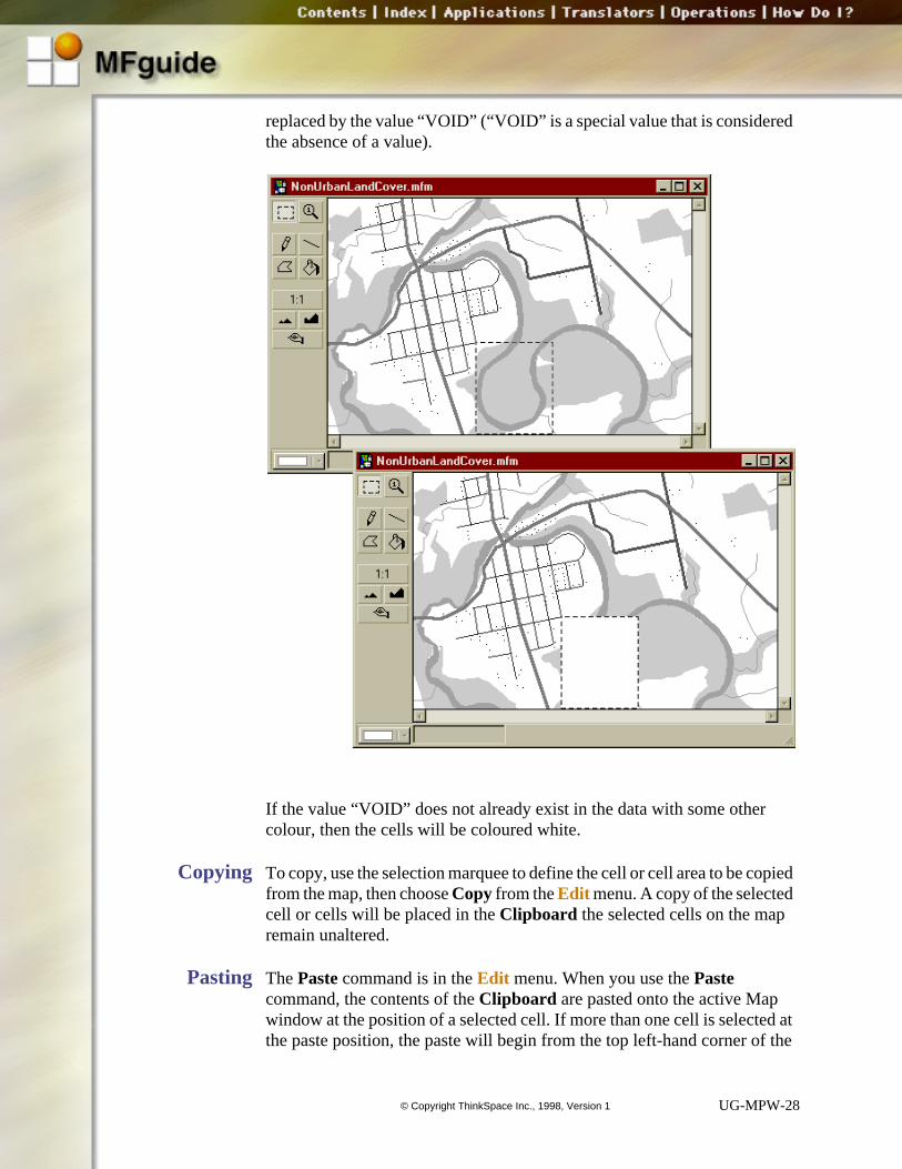
replaced by the value “VOID” (“VOID” is a special value that is considerthe absence of a value).
If the value “VOID” does not already exist in the data with some other colour, then the cells will be coloured white.
Copying To copy, use the selection marquee to define the cell or cell area to be cfrom the map, then choose Copy from the Edit menu. A copy of the selectedcell or cells will be placed in the Clipboard the selected cells on the mapremain unaltered.
Pasting The Paste command is in the Edit menu. When you use the Paste command, the contents of the Clipboard are pasted onto the active Map window at the position of a selected cell. If more than one cell is selectethe paste position, the paste will begin from the top left-hand corner of
UG-MPW-28© Copyright ThinkSpace Inc., 1998, Version 1

bjects
be
nd er y 5
nd rts
marquee and continue until the full contents of the Clipboard are pasted onto the map. Only map fragments can be pasted onto a map text and ocannot be pasted from the Clipboard into a Map window.
The size of the cell area that is pasted onto the receiving map cannot constrained by the selection marquee. Whatever is in the Clipboard will be pasted onto the receiving map beginning at the selected cell position awill replace the equivalent number of cells in the receiving map. In othwords, if the selection marquee on the receiving map defines a 5 cell bcell area, but a 10 cell by 10 cell area was placed into the Clipboard from the source map, then a 10 cell by 10 cell area will be pasted onto the receiving map.
If the area being pasted from the Clipboard is too large to fit onto the receiving map, then MFworks will fit as much as it can onto the map awill crop the excess cells at the edge of the map. The paste always sta
UG-MPW-29© Copyright ThinkSpace Inc., 1998, Version 1

left-
are
f the w,
n,
from the top left-hand corner of the selection and matches it to the tophand corner of the area in the Clipboard .
The colours of the cells in the area being pasted from the Clipboard are re-coloured to reflect the colour scheme of the receiving map layer if thereidentical values in the source map layer and the receiving map layer.
There are some restrictions on what can be pasted to a Map window. IClipboard contents were not cut or copied from a MFworks Map windothe contents cannot be pasted into the Map window. The source and receiving map layers must be of the same data type (floating point or fixed point) however, they do not have to have the same origin, cell resolutiodata units, or azimuth. A MFworks map layer can be pasted to other applications. The map fragment will become a EMF graphic in other applications.
1. Select and copy cell area to clipboard
2. Select paste position by clicking on a cell
3. Paste the contents of the clipboard
UG-MPW-30© Copyright ThinkSpace Inc., 1998, Version 1

ap
, the f the
is a me
If a cell position is not defined with the selection tool in the receiving Mwindow, MFworks will locate the paste position based on the cell coordinates of the paste area and the receiving map layer. In this casecoordinates of the cells being pasted must be coincidental with those oreceiving map layer or the following error message will be posted:
Pasting does not clear the contents of the Clipboard . It is possible to paste the same selection several times. The selection will be lost under the following circumstances:
• If something new is copied into the Clipboard
• MFworks is quit and restarted
• The computer is shut down.
Paste to newmap
The Clipboard commands can be used to create a new map layer thatsubscene of the source map layer. The new map layer will have the sacharacteristics as the source map layer including the same data type, azimuth, cell resolution, data units, and colour scheme for those zones
UG-MPW-31© Copyright ThinkSpace Inc., 1998, Version 1

mns n.
lue
can er
contained within the subscene. The origin and number of rows and coluof the new map layer will depend on the origin and size of the selectio
After cutting or copying a selection from the source map layer, choosePaste To New Map from the Edit menu. A new map layer will be createdand added to the open project. Save the map layer to make it permanent.
Clearing Use Clear to change all the cells within the selection marquee to the va“VOID”. From the Edit menu, choose Clear. Nothing is copied to the Clipboard .
Selecting all Select All is a shortcut command when you want to perform an editingcommand on the whole map layer. For example, the whole map layer be copied to the Clipboard and then pasted into a map mosaic. It is fastto choose Select All from the Edit menu, than it is to click on the selection
UG-MPW-32© Copyright ThinkSpace Inc., 1998, Version 1

rly
ls by
e
er. If rks
dits.
tool and drag a marquee around the whole map layer. This is particulatrue if the map layer is larger than the viewing window.
The Clipboard has a design limit of 32 kilobytes for efficient cutting andpasting. It is recommended that the operations Subscene and Cover be used when fragments of map layers are greater than approximately 250 cel250 cells.
Undoing EditsSometimes you will make a mistake while using the drawing tools or thediting commands. Fortunately MFworks comes equipped with an Undo command that allows you to undo the last change made to the map layyou realize that you really did want to make the change after all, MFwoallows a redo.
Caution: MFworks only supports one level of Undo/Redo if any additionaledits are made to a map layer, it will not be possible to undo previous e
To undo the last edit to the Map window, choose Undo from the File menu.
To redo the last edit to the Map window, choose Redo from the File menu. As soon as the Undo command is used, it will be replaced in the File menu by the Redo command.
UG-MPW-33© Copyright ThinkSpace Inc., 1998, Version 1