OVERVIEW OF THE PROCEDURE - McCrometer
19
Copyright © 2016 McCrometer, Inc. All printed material should not be changed or altered without permission of McCrometer. Any published technical data and instructions are subject to change without notice. Contact your McCrometer representative for current technical data and instructions. www.mccrometer.com 3255 WEST STETSON AVENUE • HEMET, CALIFORNIA 92545 USA TEL: 951-652-6811 • 800-220-2279 • FAX: 951-652-3078 Printed In The U.S.A. Lit. # 30122-40 Rev. 1.0 / 3-1-17 Page 1 of 19 ™ FlowConnect This retrofit requires the flow meter to be completely removed from the pipe. WITH THIS REPLACE THIS This describes the procedure for retrofitting a Mc Propeller mechanical flow meter to a FlowConnect unit. It requires the following: OVERVIEW OF THE PROCEDURE Retrofit Instruction: From Mc Propeller mechanical unit to remote mount FlowConnect unit, converting the drive shaft 1 - Retrofit Procedure STEP 1: Inventory the parts STEP 2: Prepare a remote area for the telemetry equipment STEP 3: Run power and sensor cables STEP 4: Remove the flow meter from the pipe STEP 5: Remove the mechanical unit and base plate STEP 6: Convert drive assembly from mechanical to FlowCom STEP 7: Install submergible remote mount kit in the meter head STEP 8: Attach the FlowConnect unit at the remote mount location STEP 9: Attach the antenna STEP 10: Connect the batteries and attach the battery cover STEP 11: Attach the tamper evident seals STEP 12: Reinstall the flow meter in the pipe 2 - Installing Sensors and Solar Panel 1: Recommended standards 2: Installing a solar panel 3: Installing a rain gauge 4: Installing a pressure sensor 3 - Connecting Inputs and Outputs 1: Power connector 2: Inputs connector 3: Outputs connector 4 - Setting the New FlowCom Register STEP 1: Enter PROGRAMMING MODE STEP 2: Cycle through the first menu level STEP 3: Cycle through the second menu level STEP 4: Set the total STEP 5: Exit and save settings Retrofit Instruction: From Mc Propeller mechanical unit to remote mount FlowConnect unit, converting the drive shaft ! WARNING! Never remove a meter or top plate assembly while the line is under pressure! • Removing the mechanical register from the meter head • Converting the drive shaft from mechanical to electrical • Setting up a new remote mount location.
Transcript of OVERVIEW OF THE PROCEDURE - McCrometer
Copyright © 2016 McCrometer, Inc. All printed material should not be changed or altered without permission of McCrometer. Any published technical data and instructions are subject to change without notice. Contact your McCrometer representative for current technical data and instructions.
www.mccrometer.com
3255 WEST STETSON AVENUE • HEMET, CALIFORNIA 92545 USATEL: 951-652-6811 • 800-220-2279 • FAX: 951-652-3078 Printed In The U.S.A. Lit. # 30122-40 Rev. 1.0 / 3-1-17
Page 1 of 19
™FlowConnect
This retrofit requires the flow meter to be completely removed from the pipe.
WITH THISREPLACE THIS
This describes the procedure for retrofitting a Mc Propeller mechanical flow meter to a FlowConnect unit. It requires the following:
OVERVIEW OF THE PROCEDURE
Retrofit Instruction: From Mc Propeller mechanical unit to remote mount FlowConnect unit, converting the drive shaft
1 - Retrofit ProcedureSTEP 1: Inventory the partsSTEP 2: Prepare a remote area for the telemetry
equipmentSTEP 3: Run power and sensor cablesSTEP 4: Remove the flow meter from the pipeSTEP 5: Remove the mechanical unit and base
plateSTEP 6: Convert drive assembly from mechanical
to FlowComSTEP 7: Install submergible remote mount kit in
the meter headSTEP 8: Attach the FlowConnect unit at the
remote mount locationSTEP 9: Attach the antennaSTEP 10: Connect the batteries and attach the
battery coverSTEP 11: Attach the tamper evident sealsSTEP 12: Reinstall the flow meter in the pipe
2 - Installing Sensors and Solar Panel1: Recommended standards2: Installing a solar panel3: Installing a rain gauge4: Installing a pressure sensor
3 - Connecting Inputs and Outputs1: Power connector2: Inputs connector3: Outputs connector
4 - Setting the New FlowCom RegisterSTEP 1: Enter PROGRAMMING MODESTEP 2: Cycle through the first menu levelSTEP 3: Cycle through the second menu levelSTEP 4: Set the totalSTEP 5: Exit and save settings
Retrofit Instruction: From Mc Propeller mechanical unit to remote mount FlowConnect unit, converting the drive shaft
!WARNING!Never remove a meter or top plate assembly while the line is under pressure!
• Removing the mechanical register from the meter head
• Converting the drive shaft from mechanical to electrical
• Setting up a new remote mount location.
Copyright © 2016 McCrometer, Inc. All printed material should not be changed or altered without permission of McCrometer. Any published technical data and instructions are subject to change without notice. Contact your McCrometer representative for current technical data and instructions.
www.mccrometer.com
3255 WEST STETSON AVENUE • HEMET, CALIFORNIA 92545 USATEL: 951-652-6811 • 800-220-2279 • FAX: 951-652-3078 Printed In The U.S.A. Lit. # 30122-40 Rev. 1.0 / 3-1-17
Page 2 of 19
™FlowConnect
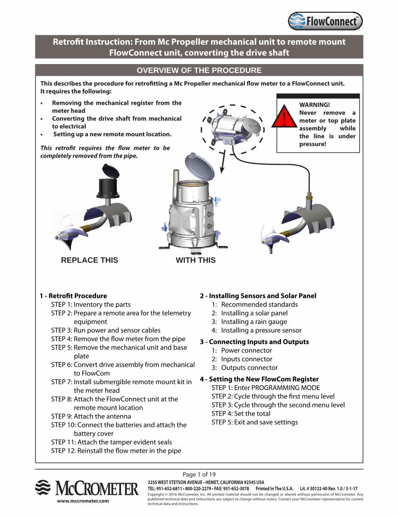
LOCATION OF ACCESSIBLE COMPONENTS
Figure 1. Accessible Components
The figure below shows the location and names of the components you will work with in this IOM.
antenna
antenna support
battery cover
base plate
canopy lidcanopy
connection plate
register (inside canopy)
NOTE: The power and sensor cables cannot be reused. They will need to be replaced with new cables with the appropriate connectors for the FlowConnect unit.
PARTS AND MATERIALS
TOOLS REQUIRED
5/32” hex driver, T-shape wrench recommendedPhillips screwdriverStandard flat head screwdriverPrecision flat head screwdriver
Part Number Description Quantity Part Number Description Quantity
30122-20 IOM Manual 1
TOB008 WS Base Plate 1TOB018 O-Ring for Base Plate 1
R139-00-K Remote mount kit:EJ543-00 FTG CBL PG11 BRS PLT 210736 O-ring 1.5 mm x 16 mm ID EPDM 1R0139-00 K adapter for PG11 fitting S316 110273 O-ring -021 110274 O-ring -121 11-1707-19 In-line Terminal 2 Position 11-1707-18 In-line Terminal 1 Position 110845 Shrink wrap tubing 3
TOB049 O-ring, wall mount bracket 11-2802 Wall mount bracket 1TOB050 #10-32 screw with O-ring 115016-10 Tamper evident seals 3EJ538-00 Plug PG7 1
10015-00 Desiccant 210804 Cable tie 210790 #6 screw x 3/16” SS 2
Sensor cable(s) 1
Antenna or antenna extension 1
Wire cutterRatchet socket driver, ½” drive1-3/8” socket
Copyright © 2016 McCrometer, Inc. All printed material should not be changed or altered without permission of McCrometer. Any published technical data and instructions are subject to change without notice. Contact your McCrometer representative for current technical data and instructions.
www.mccrometer.com
3255 WEST STETSON AVENUE • HEMET, CALIFORNIA 92545 USATEL: 951-652-6811 • 800-220-2279 • FAX: 951-652-3078 Printed In The U.S.A. Lit. # 30122-40 Rev. 1.0 / 3-1-17
Page 3 of 19
™FlowConnect
1 - Retrofit Procedure
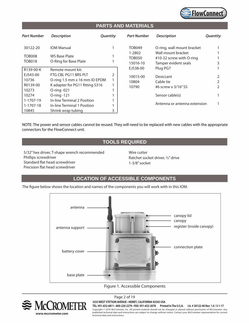
STEP 1: Inventory the parts
a. Check the parts received against the parts list on the previous page.
b. Compare the serial numbers engraved on the lids to confirm they match.
c. Confirm the serial number on the FlowConnect unit corresponds to information on a silver label located on the bottom of the base plate.
Figure 2. Checking engraved serial numbers on lids
Meter serial number engraved on enclosure lid
1x-123451x-12345
STEP 2: Prepare a remote area for the telemetry equipment
Depending on your equipment, the wiring diagram may not necessarily represent your exact configuration. For example, if you plan to use rechargeable batteries in your FlowConnect unit, you will need to have a solar panel installed of a 24V DC power supply. If you have any questions about your specific remote mount configuration, contact your McCrometer representative.
STEP 3: Run power and sensor cables
Run cables from the remote telemetry area to the meter head. At a minimum, you will need to run the sensor cables, and if you plan to install sensors or a solar panel, plan their location at the same time.
Copyright © 2016 McCrometer, Inc. All printed material should not be changed or altered without permission of McCrometer. Any published technical data and instructions are subject to change without notice. Contact your McCrometer representative for current technical data and instructions.
www.mccrometer.com
3255 WEST STETSON AVENUE • HEMET, CALIFORNIA 92545 USATEL: 951-652-6811 • 800-220-2279 • FAX: 951-652-3078 Printed In The U.S.A. Lit. # 30122-40 Rev. 1.0 / 3-1-17
Page 4 of 19
™FlowConnect
! WARNING!Never remove a meter or top plate assembly while the line is under pressure!
STEP 4: Remove the flow meter from the pipe
Remove the flow meter from the pipe as described in Section 3.0 of the Installation, Operation, and Maintenance (IOM) manual for Mc Propeller Flow meters.
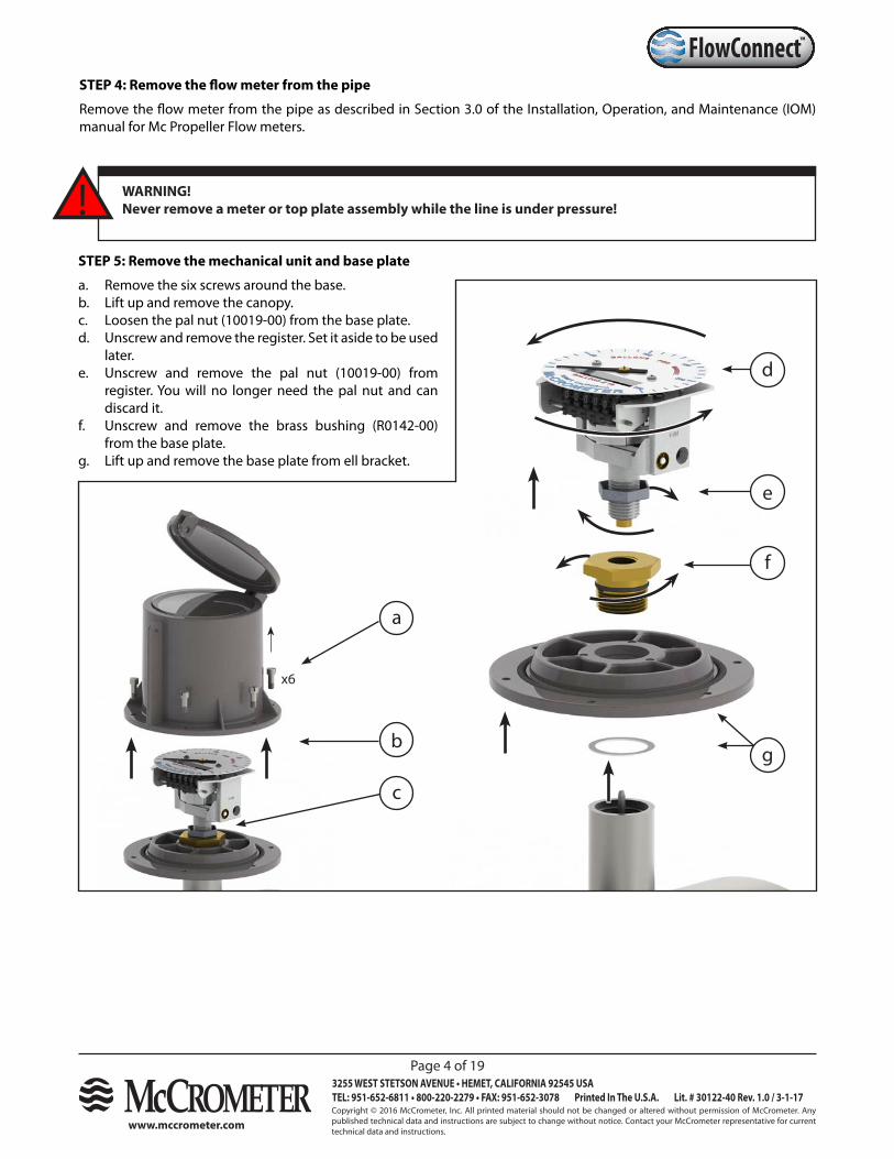
STEP 5: Remove the mechanical unit and base plate
a. Remove the six screws around the base.b. Lift up and remove the canopy.c. Loosen the pal nut (10019-00) from the base plate.d. Unscrew and remove the register. Set it aside to be used
later. e. Unscrew and remove the pal nut (10019-00) from
register. You will no longer need the pal nut and can discard it.
f. Unscrew and remove the brass bushing (R0142-00) from the base plate.
g. Lift up and remove the base plate from ell bracket.
b
x6
a
d
c
e
f
g
Copyright © 2016 McCrometer, Inc. All printed material should not be changed or altered without permission of McCrometer. Any published technical data and instructions are subject to change without notice. Contact your McCrometer representative for current technical data and instructions.
www.mccrometer.com
3255 WEST STETSON AVENUE • HEMET, CALIFORNIA 92545 USATEL: 951-652-6811 • 800-220-2279 • FAX: 951-652-3078 Printed In The U.S.A. Lit. # 30122-40 Rev. 1.0 / 3-1-17
Page 5 of 19
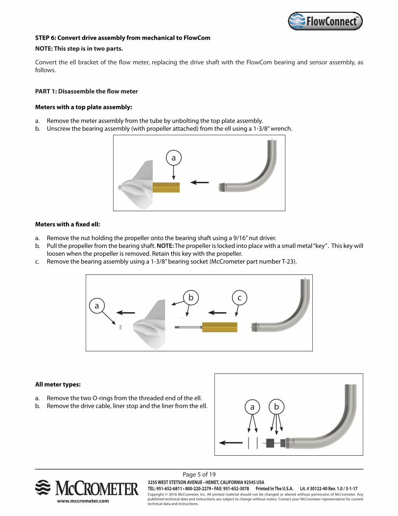
™FlowConnectSTEP 6: Convert drive assembly from mechanical to FlowCom
NOTE: This step is in two parts.
Convert the ell bracket of the flow meter, replacing the drive shaft with the FlowCom bearing and sensor assembly, as follows.
PART 1: Disassemble the flow meter
Meters with a top plate assembly:
a. Remove the meter assembly from the tube by unbolting the top plate assembly.b. Unscrew the bearing assembly (with propeller attached) from the ell using a 1-3/8” wrench.
Meters with a fixed ell:
a. Remove the nut holding the propeller onto the bearing shaft using a 9/16” nut driver.b. Pull the propeller from the bearing shaft. NOTE: The propeller is locked into place with a small metal “key” . This key will
loosen when the propeller is removed. Retain this key with the propeller.c. Remove the bearing assembly using a 1-3/8” bearing socket (McCrometer part number T-23).
All meter types:
a. Remove the two O-rings from the threaded end of the ell.b. Remove the drive cable, liner stop and the liner from the ell.
a
ca
b
a b
Copyright © 2016 McCrometer, Inc. All printed material should not be changed or altered without permission of McCrometer. Any published technical data and instructions are subject to change without notice. Contact your McCrometer representative for current technical data and instructions.
www.mccrometer.com
3255 WEST STETSON AVENUE • HEMET, CALIFORNIA 92545 USATEL: 951-652-6811 • 800-220-2279 • FAX: 951-652-3078 Printed In The U.S.A. Lit. # 30122-40 Rev. 1.0 / 3-1-17
Page 6 of 19
™FlowConnect
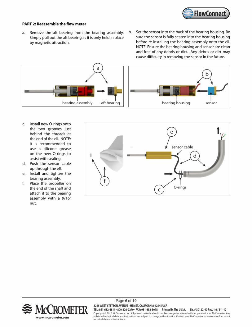
b. Set the sensor into the back of the bearing housing. Be sure the sensor is fully seated into the bearing housing before re-installing the bearing assembly onto the ell. NOTE: Ensure the bearing housing and sensor are clean and free of any debris or dirt. Any debris or dirt may cause difficulty in removing the sensor in the future.
PART 2: Reassemble the flow meter
a. Remove the aft bearing from the bearing assembly. Simply pull out the aft bearing as it is only held in place by magnetic attraction.
c
d
e
fO-rings
sensor cable
c. Install new O-rings onto the two grooves just behind the threads at the end of the ell. NOTE: it is recommended to use a silicone grease on the new O-rings to assist with sealing.
d. Push the sensor cable up through the ell.
e. Install and tighten the bearing assembly.
f. Place the propeller on the end of the shaft and attach it to the bearing assembly with a 9/16” nut.
aft bearingbearing assembly
ab
sensorbearing housing
Copyright © 2016 McCrometer, Inc. All printed material should not be changed or altered without permission of McCrometer. Any published technical data and instructions are subject to change without notice. Contact your McCrometer representative for current technical data and instructions.
www.mccrometer.com
3255 WEST STETSON AVENUE • HEMET, CALIFORNIA 92545 USATEL: 951-652-6811 • 800-220-2279 • FAX: 951-652-3078 Printed In The U.S.A. Lit. # 30122-40 Rev. 1.0 / 3-1-17
Page 7 of 19
™FlowConnect
WARNING!Over tightening the cable compression seal will damage the internal conductors, causing them to be crushed and shorted together, preventing proper operation.
!
e. Reassemble the propeller onto the bearing assembly. Ensure the propeller key is placed in the groove on the bearing before installing the propeller.
f. Test the conversion by spinning the propeller by hand and ensuring the display changes. Install the meter into the line and mount the remote FlowCom in a convenient location.
a
b
remote cable
sensor cable
drive shaft column
submergible remote mount kit
in-line terminal blocks
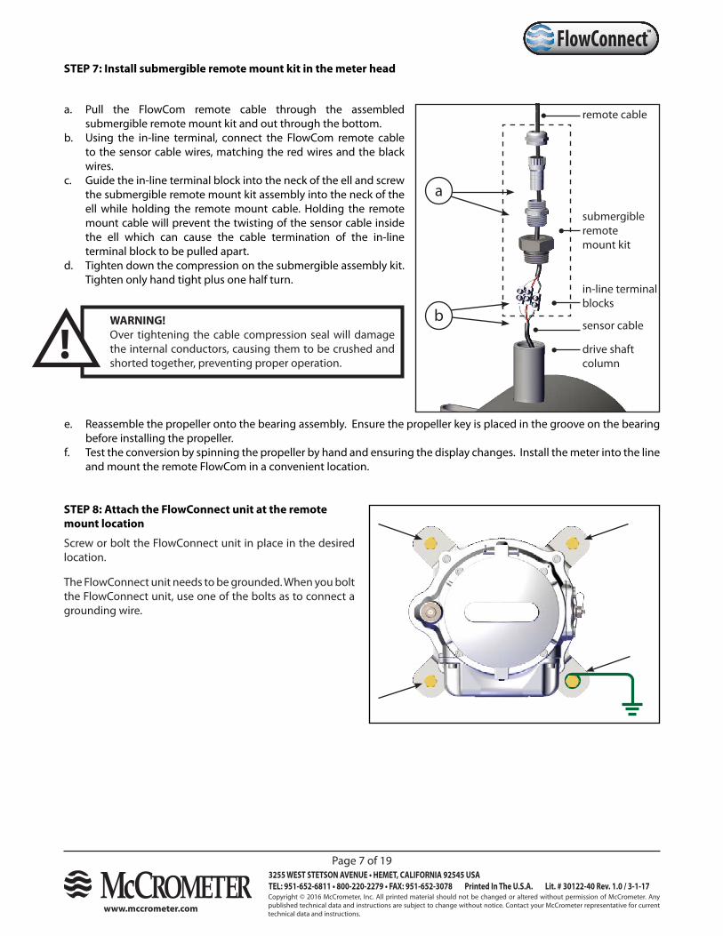
a. Pull the FlowCom remote cable through the assembled submergible remote mount kit and out through the bottom.
b. Using the in-line terminal, connect the FlowCom remote cable to the sensor cable wires, matching the red wires and the black wires.
c. Guide the in-line terminal block into the neck of the ell and screw the submergible remote mount kit assembly into the neck of the ell while holding the remote mount cable. Holding the remote mount cable will prevent the twisting of the sensor cable inside the ell which can cause the cable termination of the in-line terminal block to be pulled apart.
d. Tighten down the compression on the submergible assembly kit. Tighten only hand tight plus one half turn.
STEP 7: Install submergible remote mount kit in the meter head
STEP 8: Attach the FlowConnect unit at the remote mount location
Screw or bolt the FlowConnect unit in place in the desired location.
The FlowConnect unit needs to be grounded. When you bolt the FlowConnect unit, use one of the bolts as to connect a grounding wire.
Copyright © 2016 McCrometer, Inc. All printed material should not be changed or altered without permission of McCrometer. Any published technical data and instructions are subject to change without notice. Contact your McCrometer representative for current technical data and instructions.
www.mccrometer.com
3255 WEST STETSON AVENUE • HEMET, CALIFORNIA 92545 USATEL: 951-652-6811 • 800-220-2279 • FAX: 951-652-3078 Printed In The U.S.A. Lit. # 30122-40 Rev. 1.0 / 3-1-17
Page 8 of 19
™FlowConnect
Figure 3. Attaching the cellular antenna
Figure 4. Attaching the antenna extension
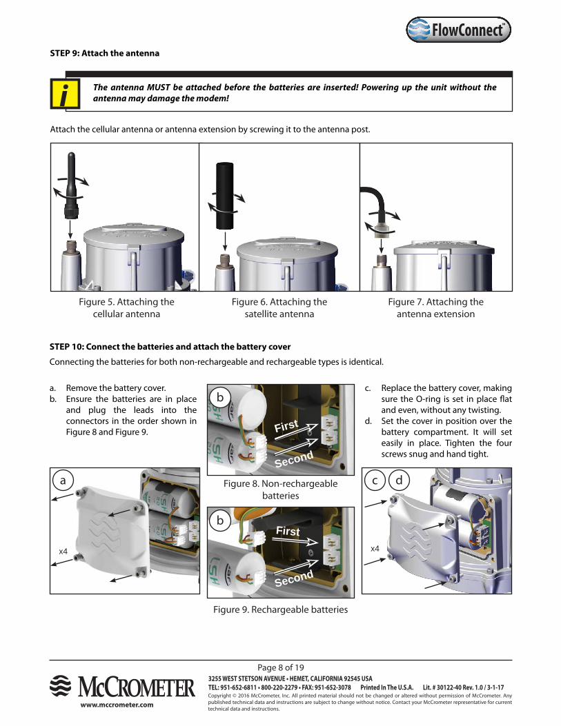
STEP 9: Attach the antenna
Figure 5. Attaching the cellular antenna
Figure 6. Attaching the satellite antenna
Attach the cellular antenna or antenna extension by screwing it to the antenna post.
Figure 7. Attaching the antenna extension
Figure 8. Non-rechargeable batteries
Figure 9. Rechargeable batteries
a. Remove the battery cover.b. Ensure the batteries are in place
and plug the leads into the connectors in the order shown in Figure 8 and Figure 9.
STEP 10: Connect the batteries and attach the battery cover
Connecting the batteries for both non-rechargeable and rechargeable types is identical.
First
First
Second
Second
x4x4
c. Replace the battery cover, making sure the O-ring is set in place flat and even, without any twisting.
d. Set the cover in position over the battery compartment. It will set easily in place. Tighten the four screws snug and hand tight.
a
b
b
c d
The antenna MUST be attached before the batteries are inserted! Powering up the unit without the antenna may damage the modem!i
Copyright © 2016 McCrometer, Inc. All printed material should not be changed or altered without permission of McCrometer. Any published technical data and instructions are subject to change without notice. Contact your McCrometer representative for current technical data and instructions.
www.mccrometer.com
3255 WEST STETSON AVENUE • HEMET, CALIFORNIA 92545 USATEL: 951-652-6811 • 800-220-2279 • FAX: 951-652-3078 Printed In The U.S.A. Lit. # 30122-40 Rev. 1.0 / 3-1-17
Page 9 of 19
™FlowConnect
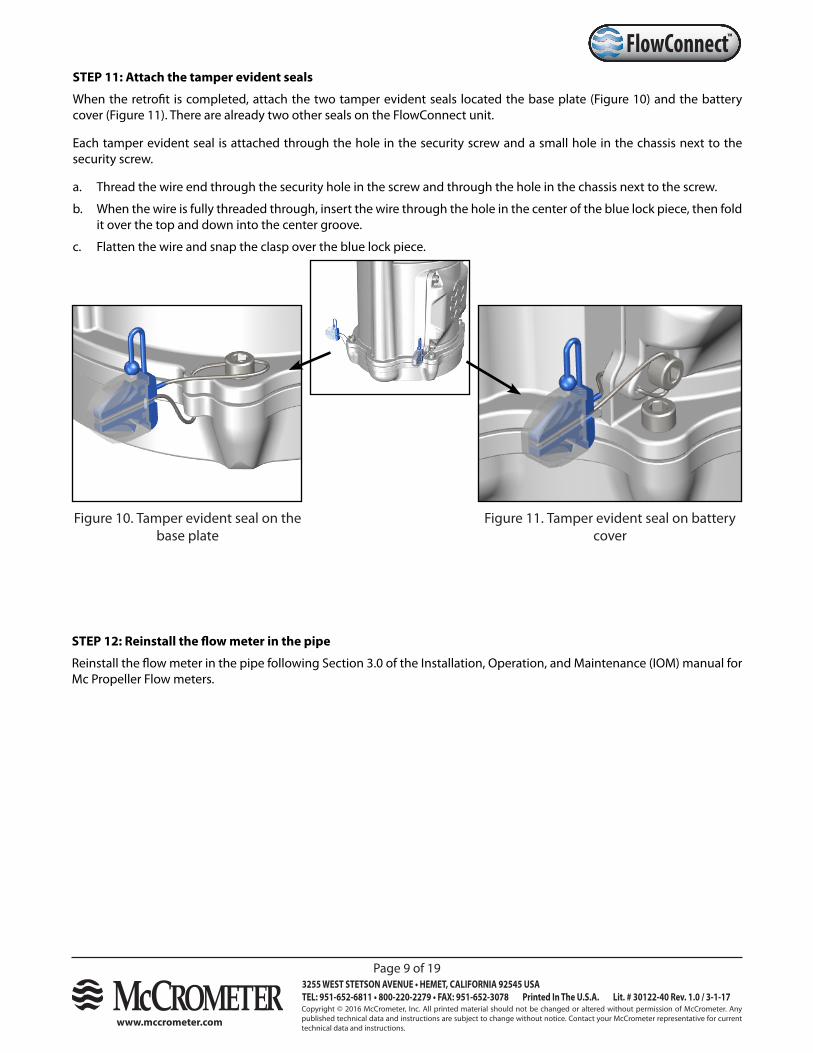
Figure 10. Tamper evident seal on the base plate
STEP 11: Attach the tamper evident seals
When the retrofit is completed, attach the two tamper evident seals located the base plate (Figure 10) and the battery cover (Figure 11). There are already two other seals on the FlowConnect unit.
Each tamper evident seal is attached through the hole in the security screw and a small hole in the chassis next to the security screw.
a. Thread the wire end through the security hole in the screw and through the hole in the chassis next to the screw.
b. When the wire is fully threaded through, insert the wire through the hole in the center of the blue lock piece, then fold it over the top and down into the center groove.
c. Flatten the wire and snap the clasp over the blue lock piece.
Figure 11. Tamper evident seal on battery cover
STEP 12: Reinstall the flow meter in the pipe
Reinstall the flow meter in the pipe following Section 3.0 of the Installation, Operation, and Maintenance (IOM) manual for Mc Propeller Flow meters.
Copyright © 2016 McCrometer, Inc. All printed material should not be changed or altered without permission of McCrometer. Any published technical data and instructions are subject to change without notice. Contact your McCrometer representative for current technical data and instructions.
www.mccrometer.com
3255 WEST STETSON AVENUE • HEMET, CALIFORNIA 92545 USATEL: 951-652-6811 • 800-220-2279 • FAX: 951-652-3078 Printed In The U.S.A. Lit. # 30122-40 Rev. 1.0 / 3-1-17
Page 10 of 19
™FlowConnect
Cable management
It is recommended that you secure sensors or extension cables near any sharp metal edges such as hose clamps.
We also recommend securing cables about every 12” - 18” along the aerial mast.
Additional site protection
Some sites may require additional protection from damage from livestock or vandalism. Fencing, cattle guards, or other measures may be necessary.
2 - Installing Sensors and Solar Panel
1: Recommended standards
Pole set
You may choose to use the McCrometer pole set, or you may use a pole set more to your preferences.
Pole and aerial height
Height of 5’ to 10’, elevating an antenna 4’ to 5’ feet above surrounding obstructions.
Pole diameter
Any pole that is 1.25” to 2” in diameter will work with McCrometer sensors.
Solar panel orientation
If you are installing a solar panel, orient it so that it is facing south in the northern hemisphere.
Securing / anchoring
There are many ways to install and secure an aerial mast for a solar panel, rain gauge, or antenna extension. We recommend installing the mast plumb. The lower part of the mast may be buried or cemented into the ground, or it may be secured to surrounding fixed objects. The installation should be secure enough to withstand the expected environmental conditions (such as strong wind) as well as foot traffic at or near the installation site.
Cable protection
We recommend you consider cable protection for use against animals, foot traffic, or vehicle traffic around the installation site. Common methods include the use of metal or flexible conduit sufficient to accommodate the ½” connectors used on solar panels and sensor cables.
The method you use to install a sensor mount will depend on the sensor type and local site conditions. The site location for a pressure sensor, the aerial mast to mount a rain gauge, or the need for cable protection, may vary.
Because each user’s requirements and conditions will vary, McCrometer does not require any particular way of mounting or securing the sensor pole. However, we do provide recommended standards for how your sensor mount should be installed. These standards are flexible enough to allow you to install your sensors under most conditions while being able to take into account your local circumstances.
Copyright © 2016 McCrometer, Inc. All printed material should not be changed or altered without permission of McCrometer. Any published technical data and instructions are subject to change without notice. Contact your McCrometer representative for current technical data and instructions.
www.mccrometer.com
3255 WEST STETSON AVENUE • HEMET, CALIFORNIA 92545 USATEL: 951-652-6811 • 800-220-2279 • FAX: 951-652-3078 Printed In The U.S.A. Lit. # 30122-40 Rev. 1.0 / 3-1-17
Page 11 of 19
™FlowConnect
Tools and Materials:
Solar Panel kit (200.733.522 or 200.733.520)7 mm socket driver5-pin male to female extension cable
Use a hose clamp and 7 mm socket driver to attach the solar panel to the top of the pole.
Orient the solar panel south so that it gets a maximum amount of light.
Connect the extension cable to the solar panel. When you are finished, the other end of the cable will be plugged into the FlowConnect unit (see next section).
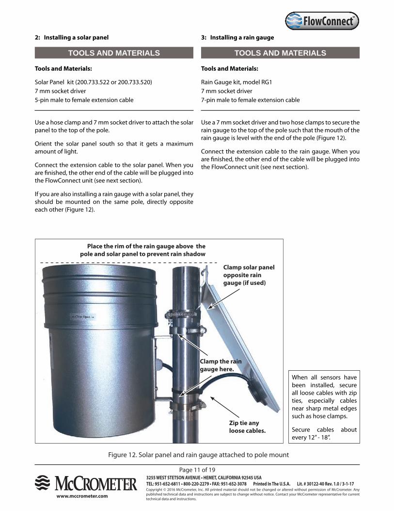
If you are also installing a rain gauge with a solar panel, they should be mounted on the same pole, directly opposite each other (Figure 12).
2: Installing a solar panel 3: Installing a rain gauge
Tools and Materials:
Rain Gauge kit, model RG17 mm socket driver 7-pin male to female extension cable
Use a 7 mm socket driver and two hose clamps to secure the rain gauge to the top of the pole such that the mouth of the rain gauge is level with the end of the pole (Figure 12).
Connect the extension cable to the rain gauge. When you are finished, the other end of the cable will be plugged into the FlowConnect unit (see next section).
Figure 12. Solar panel and rain gauge attached to pole mount
TOOLS AND MATERIALS TOOLS AND MATERIALS
Clamp solar panel opposite rain gauge (if used)
Place the rim of the rain gauge above the pole and solar panel to prevent rain shadow
Clamp the rain gauge here.
Zip tie any loose cables.
When all sensors have been installed, secure all loose cables with zip ties, especially cables near sharp metal edges such as hose clamps.
Secure cables about every 12” - 18”.
Copyright © 2016 McCrometer, Inc. All printed material should not be changed or altered without permission of McCrometer. Any published technical data and instructions are subject to change without notice. Contact your McCrometer representative for current technical data and instructions.
www.mccrometer.com
3255 WEST STETSON AVENUE • HEMET, CALIFORNIA 92545 USATEL: 951-652-6811 • 800-220-2279 • FAX: 951-652-3078 Printed In The U.S.A. Lit. # 30122-40 Rev. 1.0 / 3-1-17
Page 12 of 19
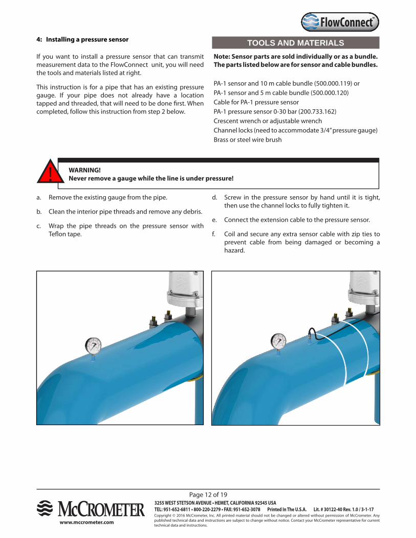
™FlowConnect4: Installing a pressure sensor
If you want to install a pressure sensor that can transmit measurement data to the FlowConnect unit, you will need the tools and materials listed at right.
This instruction is for a pipe that has an existing pressure gauge. If your pipe does not already have a location tapped and threaded, that will need to be done first. When completed, follow this instruction from step 2 below.
a. Remove the existing gauge from the pipe.
b. Clean the interior pipe threads and remove any debris.
c. Wrap the pipe threads on the pressure sensor with Teflon tape.
! WARNING!Never remove a gauge while the line is under pressure!
d. Screw in the pressure sensor by hand until it is tight, then use the channel locks to fully tighten it.
e. Connect the extension cable to the pressure sensor.
f. Coil and secure any extra sensor cable with zip ties to prevent cable from being damaged or becoming a hazard.
TOOLS AND MATERIALSNote: Sensor parts are sold individually or as a bundle. The parts listed below are for sensor and cable bundles.
PA-1 sensor and 10 m cable bundle (500.000.119) orPA-1 sensor and 5 m cable bundle (500.000.120)Cable for PA-1 pressure sensorPA-1 pressure sensor 0-30 bar (200.733.162)Crescent wrench or adjustable wrenchChannel locks (need to accommodate 3/4” pressure gauge)Brass or steel wire brush
Copyright © 2016 McCrometer, Inc. All printed material should not be changed or altered without permission of McCrometer. Any published technical data and instructions are subject to change without notice. Contact your McCrometer representative for current technical data and instructions.
www.mccrometer.com
3255 WEST STETSON AVENUE • HEMET, CALIFORNIA 92545 USATEL: 951-652-6811 • 800-220-2279 • FAX: 951-652-3078 Printed In The U.S.A. Lit. # 30122-40 Rev. 1.0 / 3-1-17
Page 13 of 19
™FlowConnect
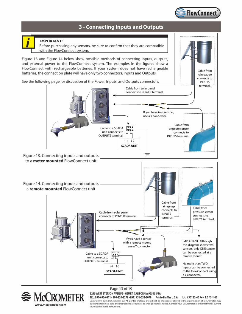
3 - Connecting Inputs and Outputs
IMPORTANT!Before purchasing any sensors, be sure to confirm that they are compatible with the FlowConnect system.
i
SENSOR CABLE
* EARTH GROUND CABLES EACH HAVE GREEN WIRE SINGLE END CRIMPED* EARTH GROUND CABLES EACH HAVE GREEN WIRE SINGLE END CRIMPED
Cable to a SCADA unit connects to
OUTPUTS terminal.
If you have two sensors, use a Y connector.
SCADA UNIT
(+) (−)
SCADA UNIT
(+) (−)
Cable from solar panel connects to POWER terminal.
Cable from rain gauge connects to
INPUTS terminal.
Cable from pressure sensor
connects to INPUTS terminal.
Cable to a SCADA unit connects to
OUTPUTS terminal.
If you have a sensor with a remote mount,
use a Y connector.
IMPORTANT: Although this diagram shows two sensors, only ONE sensor can be connected at a remote mount.
No more than TWO inputs can be connected to the FlowConnect using a Y connector.
SCADA UNIT
(+) (−)
SCADA UNIT
(+) (−)
Cable from solar panel connects to POWER terminal.
Cable from rain gauge connects to INPUTS terminal.
Cable from pressure sensor connects to INPUTS terminal.
Figure 13 and Figure 14 below show possible methods of connecting inputs, outputs, and external power to the FlowConnect system. The examples in the figures show a FlowConnect with rechargeable batteries. If your system does not have rechargeable batteries, the connection plate will have only two connectors, Inputs and Outputs.
See the following page for discussion of the Power, Inputs, and Outputs connectors.
Figure 13. Connecting inputs and outputs to a meter mounted FlowConnect unit
Figure 14. Connecting inputs and outputs a remote mounted FlowConnect unit
Copyright © 2016 McCrometer, Inc. All printed material should not be changed or altered without permission of McCrometer. Any published technical data and instructions are subject to change without notice. Contact your McCrometer representative for current technical data and instructions.
www.mccrometer.com
3255 WEST STETSON AVENUE • HEMET, CALIFORNIA 92545 USATEL: 951-652-6811 • 800-220-2279 • FAX: 951-652-3078 Printed In The U.S.A. Lit. # 30122-40 Rev. 1.0 / 3-1-17
Page 14 of 19
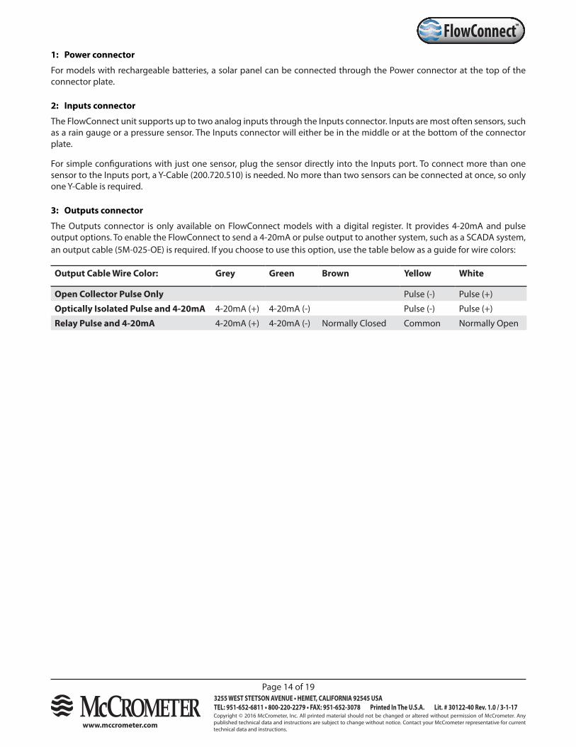
™FlowConnect1: Power connector
For models with rechargeable batteries, a solar panel can be connected through the Power connector at the top of the connector plate.
2: Inputs connector
The FlowConnect unit supports up to two analog inputs through the Inputs connector. Inputs are most often sensors, such as a rain gauge or a pressure sensor. The Inputs connector will either be in the middle or at the bottom of the connector plate.
For simple configurations with just one sensor, plug the sensor directly into the Inputs port. To connect more than one sensor to the Inputs port, a Y-Cable (200.720.510) is needed. No more than two sensors can be connected at once, so only one Y-Cable is required.
3: Outputs connector
The Outputs connector is only available on FlowConnect models with a digital register. It provides 4-20mA and pulse output options. To enable the FlowConnect to send a 4-20mA or pulse output to another system, such as a SCADA system, an output cable (5M-025-OE) is required. If you choose to use this option, use the table below as a guide for wire colors:
Output Cable Wire Color: Grey Green Brown Yellow White
Open Collector Pulse Only Pulse (-) Pulse (+)
Optically Isolated Pulse and 4-20mA 4-20mA (+) 4-20mA (-) Pulse (-) Pulse (+)
Relay Pulse and 4-20mA 4-20mA (+) 4-20mA (-) Normally Closed Common Normally Open
Copyright © 2016 McCrometer, Inc. All printed material should not be changed or altered without permission of McCrometer. Any published technical data and instructions are subject to change without notice. Contact your McCrometer representative for current technical data and instructions.
www.mccrometer.com
3255 WEST STETSON AVENUE • HEMET, CALIFORNIA 92545 USATEL: 951-652-6811 • 800-220-2279 • FAX: 951-652-3078 Printed In The U.S.A. Lit. # 30122-40 Rev. 1.0 / 3-1-17
Page 15 of 19
™FlowConnect
4 - Setting the New FlowCom Register
Brief explanation of why this is necessary:
After a FlowCom unit has been replaced with a new FlowConnect unit, users may want to set the register with the total gallons amount from the previous register. The instructions below are a concise guide to programming and resetting the total gallons only.
See the FlowCom IOM for complete procedures and description of FlowCom programming and features.
RECOVERY FROM ERROR
It is possible to make a wrong selection when programming the FlowCom register. If this happens, you can recover from the error by doing the following:
Cycle through the menu selections
• If you remember the original value, cycle through all of the values until you come to the selection you want.
Time out the programming mode
• If you can’t find the value you want or find the menu you need, allow the programming mode to time itself out. This is done by making no selections or changes while the digital display is still flashing and waiting about 30 - 60 seconds.
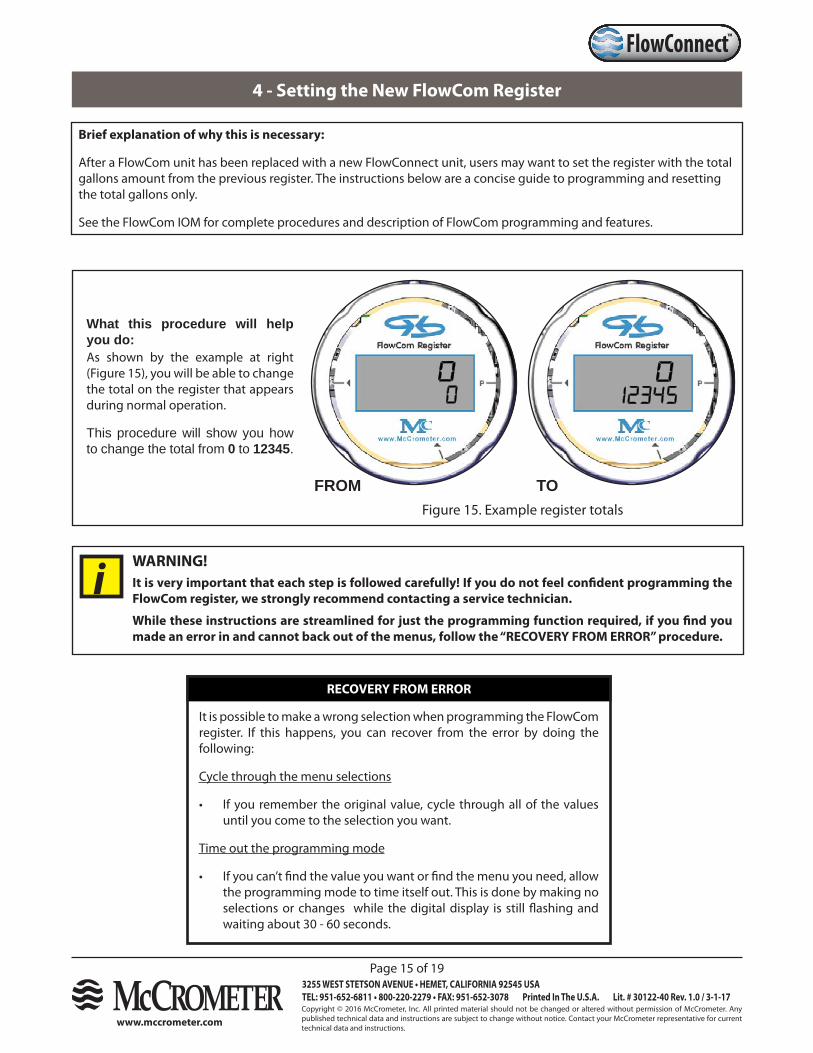
What this procedure will help you do:As shown by the example at right (Figure 15), you will be able to change the total on the register that appears during normal operation.
This procedure will show you how to change the total from 0 to 12345.
FROM TOFigure 15. Example register totals
It is very important that each step is followed carefully! If you do not feel confident programming the FlowCom register, we strongly recommend contacting a service technician.
While these instructions are streamlined for just the programming function required, if you find you made an error in and cannot back out of the menus, follow the “RECOVERY FROM ERROR” procedure.
WARNING!
i
Copyright © 2016 McCrometer, Inc. All printed material should not be changed or altered without permission of McCrometer. Any published technical data and instructions are subject to change without notice. Contact your McCrometer representative for current technical data and instructions.
www.mccrometer.com
3255 WEST STETSON AVENUE • HEMET, CALIFORNIA 92545 USATEL: 951-652-6811 • 800-220-2279 • FAX: 951-652-3078 Printed In The U.S.A. Lit. # 30122-40 Rev. 1.0 / 3-1-17
Page 16 of 19
™FlowConnect
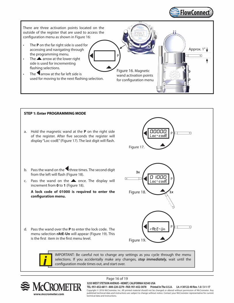
There are three activation points located on the outside of the register that are used to access the configuration menu as shown in Figure 16:
• The P on the far right side is used for accessing and navigating through the programming menu.
• The arrow at the lower right side is used for incrementing flashing selections.
• The arrow at the far left side is used for moving to the next flashing selection.
Approx. 1”
Figure 16. Magnetic wand activation points for configuration menu
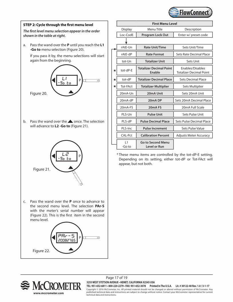
STEP 1: Enter PROGRAMMING MODE
P
P
b. Pass the wand on the three times. The second digit from the left will flash (Figure 18).
c. Pass the wand on the once. The display will increment from 0 to 1 (Figure 18).
A lock code of 01000 is required to enter the configuration menu.
P
P
3x
1x
Figure 17.
Figure 18.
Figure 19.
a. Hold the magnetic wand at the P on the right side of the register. After five seconds the register will display “Loc-codE” (Figure 17). The last digit will flash.
d. Pass the wand over the P to enter the lock code. The menu selection rAtE-Un will appear (Figure 19). This is the first item in the first menu level.
IMPORTANT: Be careful not to change any settings as you cycle through the menu selections. If you accidentally make any changes, stop immediately, wait until the configuration mode times out, and start over.i
Copyright © 2016 McCrometer, Inc. All printed material should not be changed or altered without permission of McCrometer. Any published technical data and instructions are subject to change without notice. Contact your McCrometer representative for current technical data and instructions.
www.mccrometer.com
3255 WEST STETSON AVENUE • HEMET, CALIFORNIA 92545 USATEL: 951-652-6811 • 800-220-2279 • FAX: 951-652-3078 Printed In The U.S.A. Lit. # 30122-40 Rev. 1.0 / 3-1-17
Page 17 of 19
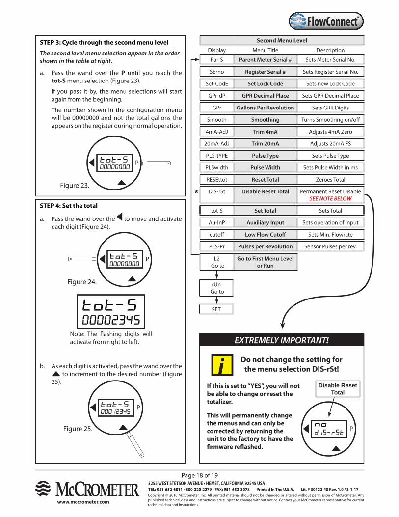
™FlowConnectSTEP 2: Cycle through the first menu level
The first level menu selection appear in the order shown in the table at right.
a. Pass the wand over the P until you reach the L1 -Go to menu selection (Figure 20).
If you pass it by, the menu selections will start again from the beginning.
First Menu Level
Display Menu Title Description
Loc-CodE Program Lock Out Enter w/ preset code
rAtE-Un Rate Unit/Time Sets Unit/Time
rAtE-dP Rate Format Sets Rate Decimal Place
tot-Un Totalizer Unit Sets Unit
tot-dP-E Totalizer Decimal Point Enable
Enables/Disables Totalizer Decimal Point
tot-dP Totalizer Decimal Place Sets Decimal Place
Tot-FAct Totalizer Multiplier Sets Multiplier
20mA-Un 20mA Unit Sets 20mA Unit
20mA-dP 20mA DP Sets 20mA Decimal Place
20mA-FS 20mA FS 20mA Full Scale
PLS-Un Pulse Unit Sets Pulse Unit
PLS-dP Pulse Decimal Place Sets Pulse Decimal Place
PLS-Inc Pulse Increment Sets Pulse Value
CAL-Pct Calibration Percent Adjusts Meter Accuracy
L1-Go to
Go to Second Menu Level or Run
* These menu items are controlled by the tot-dP-E setting. Depending on its setting, either tot-dP or Tot-FAct will appear, but not both.
Figure 20.
b. Pass the wand over the once. The selection will advance to L2 -Go to (Figure 21).
Figure 21.
c. Pass the wand over the P once to advance to the second menu level. The selection PAr-S with the meter’s serial number will appear (Figure 22). This is the first item in the second menu level.
Figure 22.
***
P
P
P
Copyright © 2016 McCrometer, Inc. All printed material should not be changed or altered without permission of McCrometer. Any published technical data and instructions are subject to change without notice. Contact your McCrometer representative for current technical data and instructions.
www.mccrometer.com
3255 WEST STETSON AVENUE • HEMET, CALIFORNIA 92545 USATEL: 951-652-6811 • 800-220-2279 • FAX: 951-652-3078 Printed In The U.S.A. Lit. # 30122-40 Rev. 1.0 / 3-1-17
Page 18 of 19
™FlowConnectSTEP 3: Cycle through the second menu level
The second level menu selection appear in the order shown in the table at right.
a. Pass the wand over the P until you reach the tot-S menu selection (Figure 23).
If you pass it by, the menu selections will start again from the beginning.
The number shown in the configuration menu will be 00000000 and not the total gallons the appears on the register during normal operation.
Second Menu Level
Display Menu Title Description
Par-S Parent Meter Serial # Sets Meter Serial No.
SErno Register Serial # Sets Register Serial No.
Set-CodE Set Lock Code Sets new Lock Code
GPr-dP GPR Decimal Place Sets GPR Decimal Place
GPr Gallons Per Revolution Sets GRR Digits
Smooth Smoothing Turns Smoothing on/off
4mA-AdJ Trim 4mA Adjusts 4mA Zero
20mA-AdJ Trim 20mA Adjusts 20mA FS
PLS-tYPE Pulse Type Sets Pulse Type
PLSwidth Pulse Width Sets Pulse Width in ms
RESEttot Reset Total Zeroes Total
DIS-rSt Disable Reset Total Permanent Reset DisableSEE NOTE BELOW
tot-S Set Total Sets Total
Au-InP Auxiliary Input Sets operation of input
cutoff Low Flow Cutoff Sets Min. Flowrate
PLS-Pr Pulses per Revolution Sensor Pulses per rev.
L2-Go to
Go to First Menu Level or Run
SET
rUn-Go to
Figure 23.
Figure 24.
Figure 25.
b. As each digit is activated, pass the wand over the to increment to the desired number (Figure
25).
STEP 4: Set the total
a. Pass the wand over the to move and activate each digit (Figure 24).
Note: The flashing digits will activate from right to left.
*
P
P
P
Do not change the setting for the menu selection DIS-rSt!
P
EXTREMELY IMPORTANT!
Disable Reset Total
If this is set to “YES”, you will not be able to change or reset the totalizer.
This will permanently change the menus and can only be corrected by returning the unit to the factory to have the firmware reflashed.
i
Copyright © 2016 McCrometer, Inc. All printed material should not be changed or altered without permission of McCrometer. Any published technical data and instructions are subject to change without notice. Contact your McCrometer representative for current technical data and instructions.
www.mccrometer.com
3255 WEST STETSON AVENUE • HEMET, CALIFORNIA 92545 USATEL: 951-652-6811 • 800-220-2279 • FAX: 951-652-3078 Printed In The U.S.A. Lit. # 30122-40 Rev. 1.0 / 3-1-17
Page 19 of 19
™FlowConnect
P
P
P
NOTE: At the L2 - Go To selection, if you pass the wand over P to move to the second menu level, the selection rUn - Go to will appear. Then if you make a second pass over P, any changes made will be set.
STEP 5: Exit and save settings
Note: If you do not save your settings and allow the configuration mode to time out, your settings will be lost.
b. Pass the wand over to increment to the rUn - Go selection (Figure 27).
c. Pass the wand over P. This will end configuration mode and save your changes (Figure 28).
P
a. Pass the wand over the P until you reach the L2 - Go To selection (Figure 26).
Figure 26.
Figure 27.
Figure 28.