Overview of the AMR concept Global System for Mobile ... · Overview of the AMR concept oUnlike...
16
Global System for Mobile Communications (GSM) Eloi Batlle Digital Speech Processing Universitat Pompeu Fabra Overview of the AMR concept o Unlike previous GSM codecs which operate at a fixed rate and constant error protection level, AMR adapts to the local radio channel and traffic conditions o Full-rate only for maximum robustness to channel errors o Half-rate only for maximum capacity advantage Multi-rate adaptation o The AMR adaptation is based on the quality of the radio channel o Modes 7.95 kbits/s 5.90 kbits/s 7.40 kbits/s 5.15 kbits/s 6.70 kbits/s 4.75 kbits/s Half-rate 12.2 kbits/s 6.70 kbits/s 10.2 kbits/s 5.90 kbits/s 7.95 kbits/s 5.15 kbits/s 7.40 kbits/s 4.75 kbits/s Full-rate bit-rate Channel Bit allocation 95 4.75 kbit/s 103 5.15 kbit/s 118 5.90 kbit/s 134 6.70 kbit/s 148 7.40 kbit/s 159 7.95 kbit/s 204 10.2 kbit/s 244 12.2 kbit/s Bits per frame Mode
Transcript of Overview of the AMR concept Global System for Mobile ... · Overview of the AMR concept oUnlike...

1
Global System for Mobile Communications (GSM)
Eloi Batlle
Digital Speech Processing
Universitat Pompeu Fabra
Overview of the AMR concept
o Unlike previous GSM codecs which operate at a fixed rate and constant error protection level, AMR adapts to the local radio channel and traffic conditions
o Full-rate only for maximum robustness to channel errors
o Half-rate only for maximum capacity advantage
Multi-rate adaptation
o The AMR adaptation is based on the quality of the radio channel
o Modes
7.95 kbits/s 5.90 kbits/s7.40 kbits/s 5.15 kbits/s6.70 kbits/s 4.75 kbits/s
Half-rate
12.2 kbits/s 6.70 kbits/s10.2 kbits/s 5.90 kbits/s7.95 kbits/s 5.15 kbits/s7.40 kbits/s 4.75 kbits/s
Full-rate
bit-rateChannel
Bit allocation
954.75 kbit/s
1035.15 kbit/s
1185.90 kbit/s
1346.70 kbit/s
1487.40 kbit/s
1597.95 kbit/s
20410.2 kbit/s
24412.2 kbit/s
Bits per frameMode

2
Transmit side Receive side
Notesn 1) 8-bit A-law or -law PCM (ITU-T recommendation G.711), 8
000 samples/s;n 2) 13-bit uniform PCM, 8 000 samples/s;n 3) Voice Activity Detector (VAD) flag;n 4) Encoded speech frame, 50 frames/s, number of bits/frame
depending on the AMR codec mode;n 5) Silence Descriptor (SID) frame (marked SID_FIRST or
SID_UPD);n 6) TX_TYPE, 2 bits, indicates whether information bits are
available and if they are speech or SID information;n 7) Information bits delivered to the radio subsystem;n 8) Information bits received from the radio subsystem;n 9) RX_TYPE, the type of frame received quantized into three
bits, (classified by the RSS).
Discontinuous transmission
o Each direction of transmission is occupied about 50% of the time
o Discontinuous transmission (DTX)n Mobile Station battery life will be prolongedn Better radio frequency spectrum efficiency
o DTX requires some functionsn Voice Activity Detector (VAD)n Comfort noise

3
Voice Activity Detection
o The input to the VAD is a set of parameters computed by the encoder
o Each 20 ms the system decides whether the frame contains speech or not
Comfort noise insertiono When transmission is on, the background
noise is transmitted together with the speech
o When the speech ends, the connection is off and the perceived noise would drop to a very low level
o This step modulation of noise may be perceived as annoying
o Comfort noisen Evaluation of background noisen Noise parameters encoding and decodingn Generation of comfort noise in the receiver
Lost speech frame substitution
o Frames may be lost due to transmission errors
o In order to mask the effect of an isolated lost frame, it is substituted by a predicted one based on previous frames
o For several lost frames, a muting technique shall be used
AMR codec homing
o All modules shall react on a given input sequence always with the corresponding bit exact output sequence, provided that the tested modules are in their home-state when starting
o Special inband signaling frames have been defined to provoke these homing-functions also in remotely placed modules

4
Frequency responseAMR Codec Frequency Response
-35
-30
-25
-20
-15
-10
-5
0
5
50 470 890 1310 1730 2150 2570 2990 3410 3830
Frequency [Hz]
[dB]
12.2 kbit/s
10.2 kbit/s
7.95 kbit/s
7.40 kbit/s
6.70 kbit/s
5.90 kbit/s
5.15 kbit/s
4.75 kbit/s
Speech encodero Pre-processingo Linear prediction analysis and quantizationo Open-loop pitch analysiso Impulse response computationo Target signal computationo Adaptive codebooko Algebraic codebooko Quantization of the adaptive and fixed
codebook gainso Memory update
Speech encoder (2)
o Speech frames of 20ms (160 samples)
o 8000 samples/s frequencyo Speech frame divided into 4
subframes of 5 ms (40 samples)o Adaptive and fixed codebook
parameters are transmitted every subframe
Speech encoder (and 3)
w indowingand a utoc orr elationR [ ]
Le vinson-Durbin
R[ ] A(z)
A(z)
LSPquantiza tion
c ompute ta rgetfor
innova tion
update filterme mories forne xt subfra me
O pe n-loop pitch se arc h Adaptive c ode bookse ar ch
Innovativ e codebookse ar ch
Filter m em oryupdate
inte rpola tion
subframe sLSP A(z)
LSP
c omputew eighte d
spee ch(4 subfra me s)
findope n-loop pitc h
find be st innova tion
fixed codebook
ga in qua ntiz ation
A(z )^
x(n)
pitchindex
codeinde x
frame subframe
s (n) c ompute targetfor a da ptivec odebook
Tofind be st de lay
a nd gain
x (n)
c omputeimpulse
re spons eA( z)^
A(z) h(n)
h(n)
A(z)
LPC analy sis(twice pe r frame )
A(z)
(twice pe r fram e)
x (n)2
qua ntizeLTP-gain
computeadaptive
codebookcontr ibution
LSPindic es
LTPgain
index
gain indexfixe d code book
inte rpola tionfor the 4
subfr amesLSP A(z)^
for the 4
Pre -proc es sing
Pr e-proc ess ing
computeexcita tion

5
Speech decoder
LSPin dices
d ecode LSP
int erpo latio n of LSP fo r th e4 su bframe s
LSP
d ecodead aptiv eco deboo k
deco deinn ovati veco debo ok
p itchi ndex
c odein dex
deco degains
A(z)^
co nstructexcit ation
frame subfram e post-processing
s'(n)^s(n)^p ost f ilter
g ainsindi ces
sy nthesisf ilter
CELP synthesis modelo Code-excited linear predictive coding model
A(z)1 s(n)^
+
v(n)
c(n)
u(n)
gc
fixedcodebook
adaptive codebook gp
LP synthesis
post-filtering s'(n)^
Pre-processing
o High-pass filteringo Down-scaling (factor of 2)
21
21
1 911376953.0906005859.11927246903.08544941.1927246093.0)( −−
−−
+−+−=
zzzzzHh
Windowing and autocorrelationo 12.2 kbits/sn Twice per frame analysis using two different
asymmetric windows with L 1(I)=160, L 2
(I)=80, L1
(II)=232 and L 2(II)=8
−+=
−−
−=
−
−=
−+=
−
−+
−=
−
−=
1,, , 14
)(2cos
,1,,0 , 12
2cos46.054.0
)(
.1,, , 1
)(cos46.054.0
,1,,0 , 1
cos46.054.0
)(
)(2
)(1
)(1)(
2
)(1
)(1)(
1
)(2
)(1
)(1)(
2
)(1
)(1)(
1
IIIIIIII
II
II
II
II
III
I
I
II
I
LLLnL
Ln
LnL
n
nw
LLLnL
Ln
LnL
n
nw
K
K
K
K
π
π
π
π

6
Windowing and autocorrelation (2)
o 12.2 kbits/s
20 ms5 ms
frame (160 sample s) sub frame(40 sa mples)
fr ame n-1 frame n
t
Iw (n)
IIw (n)
Windowing and autocorrelation (3)
o 12.2 kbits/s
n The autocorrelation is computed by
r k s n s n k kacn k
( ) ' ( ) ' ( ) , , , ,= − ==
∑239
0 10 K
o 12.2 kbits/sn A 60Hz bandwidth expansion used by lag
windowing the autocorrelation
n Where f0=60Hz is the bandwidth expansion and fs=8000Hz is the sampling frequency
Windowing and autocorrelation (4)
( )
,10,1 ),()()('
10,1,2
21
exp2
0
K
K
==
=
−=
kkwkrkr
if
ifiw
lagacac
slag
π
Windowing and autocorrelation (5)
o 12.2 kbits/sn A white noise correction factor is usedn It is equivalent to adding a noise floor of
-40dB
r rac ac' ( ) . ( )0 1 0001 0=

7
Windowing and autocorrelation (and 6)
o All other kbits/s modes
n Once per frame analysis using wII(n) window with L1=200 and L2=40
n Autocorrelation of the windowed speech and a 60Hz bandwidth expansion
n White noise correction factor of -40dB
Levinson-Durbin
[ ]( )
end)1()1()(
end
do 1 to1for
1
)('
1
do 10 to1for
)0(')0(
2
)1()1()(
)(
1
0)1(
)1(0
−−=
+=
−==
−
−−=
=
=
=
−−
−
−
=−
−
∑
iEkiE
akaa
ijka
iE
jirak
a
i
rE
i
ijii
ij
ij
ii
i
i
j acij
i
i
ac
LP to LSP conversion
o The linear prediction coefficients (LP) are converted to the line spectral pair (LSP) representation for quantization and interpolation purposes
o LSPs are defined as the roots of
( ) ( ) ( )( ) ( ) ( )111
2
1111
−−
−−
−=′
+=′
zAzzAzF
zAzzAzF
LP to LSP conversion (2)
o F1’(z) is symmetric and F2
’(z) is anti-symmetric
o All these roots are on the unit circle and they alternate each other
o F1’(z) corresponds to the vocal tract
with the glotis closed and F2’(z) with
the glotis open

8
LP to LSP conversion (3)
o F1’(z) has a root z=-1 (ω=π)
o F2’(z) has a root z=1 (ω=0)
o To eliminate these two roots we define
( ) ( ) ( )( ) ( ) ( )1
22
111
1
1−
−
−′=
+′=
zzFzF
zzFzF
o Each polynomial has 5 conjugate root on the unit circle, therefore they can be written as
o Where qi=cos(ω i) with ω i being the line spectral frequencies (LSF) and qi are the LSP in the cosine domain
LP to LSP conversion (4)
( ) ( )
( ) ( )∏
∏
=
−−
=
−−
+−=
+−=
10,,4,2
212
9,,3,1
211
21
21
K
K
ii
ii
zzqzF
zzqzF
LP to LSP conversion (5)
o The LSP are found by evaluating F1(z) and F2(z) at 60 points equally spaced between 0 and π and checking for sign changes
o The sign change interval is then divided by 4 to better track the root
LP to LSP conversion (6)
o LPC vs. LSP

9
LP to LSP conversion (and 7) LSP coefficients quantization
o 12.2 kbits/sn The two sets of LP coefficients are
quantified using the LSP representation in the frequency domain
( )ff
q iis
i= =2
1 10π
arccos , , , ,K
LSP coefficients quantization (2)
o 12.2 kbits/sn A 1st order MA prediction is applied and
the prediction residual vectors are given by
n Where z(n) are the mean-removed LSF vectors and p(n) is the predicted vector
( ) ( ) ( )( ) ( ) ( )
r z pr z p
( ) ( )
( ) ( ),,
1 1
2 2n n nn n n
= −= −
and
( ) ( )p rn n= −0 65 12. $ ( )
LSP coefficients quantization (3)
o 12.2 kbits/sn The two residual vectors are jointly
quantified using split matrix quantization (SMQ)
n The matrix (r(1) r(2)) is split into 5 submatrices of 2x2
n The 5 submatrices are quantified with 7, 8, 8+1, 8 and 6 bits respectively (the third matrix uses a signed codebook)

10
LSP coefficients quantization (4)
o All other kbits/s modesn The LP coefficients are quantified using
the representation in the frequency domain
n A 1st order MA prediction is applied
LSP coefficients quantization (and 5)
o All other kbits/s modesn The residual vector is split into 3 subvectors of
dimensions 3, 3 and 4
7884.75 kbit/s
7885.15 kbit/s
9985.90 kbit/s
9986.70 kbit/s
9987.40 kbit/s
9997.95 kbit/s
99810.2 kbit/s
Subvector 3Subvector 2Subvector 1Mode
LSP interpolation
o 12.2 kbits/sn The two sets of LP parameters are used
for the 2nd and 4th subframen 1st and 3rd subframes use a linear
interpolation of the parameters in the adjacent subframes
$ . $ . $ ,$ . $ . $ .
( ) ( ) ( )
( ) ( ) ( )q q q
q q q1 4
12
3 2 4
05 0 5
05 05
n n n
n n n= += +
−
LSP interpolation (and 2)
)(4
)1(4
)(3
)(4
)1(4
)(2
)(4
)1(4
)(1
ˆ75.0ˆ25.0ˆ
ˆ5.0ˆ5.0ˆ
ˆ25.0ˆ75.0ˆ
nnn
nnn
nnn
qqq
qqq
qqq
+=
+=
+=
−
−
−
oAll other kbits/s modesnLP parameters are used for the 4th
subframen1st, 2nd and 3rd subframes use a linear
interpolation of the parameters in the adjacent subframes

11
LSP to LP conversion
o Once the LP are quantified and interpolated, they are converted back to the LP coefficients domain
( )( )
( ) ( ) ( )
( ) ( ) ( ) ( )
endend
212 1 down to 1for
2212 5 to1for
1001
111211
11121
1
1
−+−−=−=
−+−−===
=−
−
−
jfjfqjfjfij
ififqifi
ff
i
i
LSP to LP conversion (2)
o f1’(i) and f2’(i) are found by
o And the LP coefficients by
( ) ( ) ( )( ) ( ) ( )′ = + − =′ = − − =
f i f i f i if i f i f i i
1 1 1
2 2 2
1 1 51 1 5, , ,, , ,
KK
( ) ( )( ) ( )a
f i f i i
f i f i ii =′ + ′ =
′ − − ′ − =
05 05 1 5
05 11 0 5 11 6 101 2
1 2
. . , , ,
. . , , ,
K
K
Monitoring resonance
o Resonances in the LPC filter are monitored to detect possible problems
Open-loop pitch analysis
o How to determine the location and height of the impulses?
o Based on analysis-by-synthesiso Filtering of the input signal with a
perceptual weighting filter
( ) ( ) ( )
( ) ( ) ( ) ( ) 1,,0,10
12
10
11
21
−=−−−+=
=
∑∑==
Lninsainsansns
zAzAzW
iw
ii
i
iiw Kγγ
γγ
12
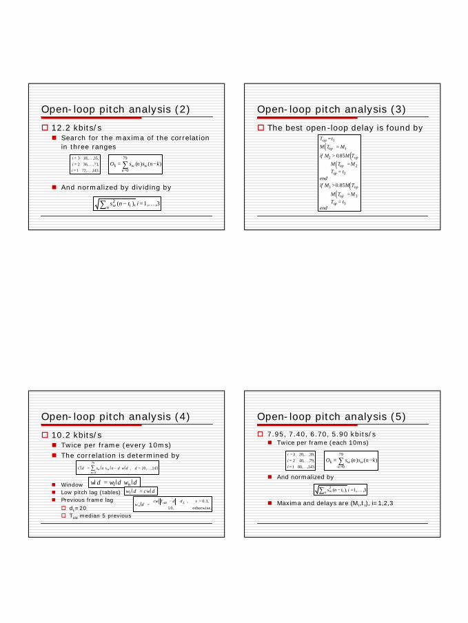
Open-loop pitch analysis (2)
o 12.2 kbits/sn Search for the maxima of the correlation
in three ranges
n And normalized by dividing by
O s n s n kk w wn
= −=∑ ( ) ( )
0
79
.143,,721,71,,362,35,,183
KKK
===
iii
s n t iw in2 ( ),− =∑ 1, ,3K
Open-loop pitch analysis (3)
o The best open-loop delay is found by
( )( )
( )
( )( )
T t
M T M
if M M T
M T MT t
endif M M T
M T MT t
end
op
op
op
op
op
op
op
op
=
=
>
==
>
==
1
1
2
2
2
3
3
3
0 85
0 85
.
.
Open-loop pitch analysis (4)
o 10.2 kbits/sn Twice per frame (every 10ms)n The correlation is determined by
n Windown Low pitch lag (tables)n Previous frame lago dL=20o Told median 5 previous
( ) ( ) ( ) ( )C d s n s n d w d dw wn
= − ==∑
0
79
20 143, , ,K
( ) ( ) ( )w d w d w dl n=( ) ( )w d cw dl =
( ) ( )w d
cw T d d vn
old L=− + >
, . ,
. ,
0 3
1 0 otherwise,
Open-loop pitch analysis (5)
o 7.95, 7.40, 6.70, 5.90 kbits/sn Twice per frame (each 10ms)
n And normalized by
n Maxima and delays are (Mi,t i), i=1,2,3
O s n s n kk w wn
= −=∑ ( ) ( )
0
79
.143,,801,79,,402,39,,203
KKK
===
iii
s n t iw in2 ( ),− =∑ 1, ,3K

13
Open-loop pitch analysis (6)
o The best open-loop delay is found by
( )( )
( )
( )( )
T t
M T M
if M M T
M T MT t
endif M M T
M T MT t
end
op
op
op
op
op
op
op
op
=
=
>
==
>
==
1
1
2
2
2
3
3
3
0 85
0 85
.
.
Open-loop pitch analysis (7)
o 5.15, 4.75 kbits/sn Once per frame (each 20ms)
n And normalized by
n Maxima and delays are (Mi,t i), i=1,2,3
O s n s n kk w wn
= −=∑ ( ) ( )
0
79
.143,,801,79,,402,39,,203
KKK
===
iii
s n t iw in2 ( ),− =∑ 1, ,3K
Open-loop pitch analysis (and 8)
o The best open-loop delay is found by
( )( )
( )
( )( )
T t
M T M
if M M T
M T MT t
endif M M T
M T MT t
end
op
op
op
op
op
op
op
op
=
=
>
==
>
==
1
1
2
2
2
3
3
3
0 85
0 85
.
.
Impulse response
o The impulse response of the weighted synthesis filter is computed each subframe
o This impulse response will be used for the search of codebooks
( ) ( ) ( ) ( ) ( )[ ]H z W z A z A z A z= γ γ1 2$

14
Adaptive codebook
o Adaptive codebook search is performed on a subframe basis
o The parameters are the delay and gain of the pitch filter
o The codebook contain entries taken from the previously synthesized excitation signal
Algebraic codebook
o Based on interleaved single -pulse permutation (ISPP) designn A few sparse impulse sequences that are
phase-shifted versions of each othern All the pulses have the same magnituden Amplitudes are +1 or -1
Algebraic codebook (and 2)o 12.2 kbits/sn 10 non-zero pulses
o 10.2 kbits/sn 8 non-zero pulses
o 7.95, 7.40 kbits/sn 4 non-zero pulses
o 6.70 kbits/sn 3 non-zero pulses
o 5.90, 5.15, 4.75 kbits/sn 2 non-zero pulses
CELP synthesis modelo Code-excited linear predictive coding model
A(z)1 s(n)^
+
v(n)
c(n)
u(n)
gc
fixedcodebook
adaptive codebook gp
LP synthesis
post-filtering s'(n)^

15
CELP synthesis model (and 2)
o To reconstruct speechn A noise-like excitation modeln A pitch filter model of the glottal
vibrationsn A linear prediction filter model of the
vocal tract
Speech decoder
LSPin dices
d ecode LSP
int erpo latio n of LSP fo r th e4 su bframe s
LSP
d ecodead aptiv eco deboo k
deco deinn ovati veco debo ok
p itchi ndex
c odein dex
deco degains
A(z)^
co nstructexcit ation
frame subfram e post-processing
s'(n)^s(n)^p ost f ilter
g ainsindi ces
sy nthesisf ilter
Speech decoder (2)
o Decodingn LP parametersn Adaptive codebook vectorn Adaptive codebook gainn Innovative codebook vectorn Innovative codebook gain
o Smoothing of the fixed codebook gaino Anti-sparseness processingo Speech synthesis
Adaptive codevector
o The received pitch index is used to find the integer and fractional parts of the pitch lag
o The adaptive codebook vector v(n) is obtained by interpolating the past excitation u(n) at the pitch delay
o The received index is used to find the quantised adaptive codebook gain gpfrom the quantisation table

16
Algebraic codebook
o The received index is used to extract the positions and amplitude signs of the excitation pulses and to find the algebraic code vector c(n)
o The received index is used to compute the quantised fixed codebook gain gc
Reconstructing speech
o The input excitation is
o The excitation is filtered by the LP filter
( ) ( ) ( )ncgnvgnu cp +=
( ) ( ) ( )zUzA
zY 1=