Overview of Proflux technologies 27 april 2013
23
-
Upload
dr-jeff-forsyth -
Category
Business
-
view
239 -
download
3
description
Overview of Oilflow Solutions Technologies
Transcript of Overview of Proflux technologies 27 april 2013

Page 2 of 23
TABLE OF CONTENTS
1 OILFLOW SOLUTIONS ............................................................................. 3
1.1 Proflux properties and characteristics ........................................................................... 3 1.2 Proflux technology ........................................................................................................ 4
2 WELL APPLICATIONS .............................................................................. 5
2.1 Wellflux properties and characteristics ......................................................................... 5 2.2 Wellflux applications in cold production ...................................................................... 6
2.2.1 Viscosity constrained wells ........................................................................................ 6 2.2.2 High water cuts wells ................................................................................................. 6 2.2.3 Case studies ................................................................................................................ 7 2.3 Wellflux application in thermal production .................................................................. 8
2.3.1 CSS wells ................................................................................................................... 8 2.3.2 SAGD wedge/infill wells ......................................................................................... 10 2.4 Well servicing applications ......................................................................................... 10 2.4.1 Well loads ................................................................................................................ 10
2.4.2 Flush by .................................................................................................................... 10 2.4.3 Tubing flush and kill ................................................................................................ 10
2.4.4 Rod side coil flushes ................................................................................................ 11 2.4.5 Perforation washes and near well bore stimulations ................................................ 11
2.4.6 Instrumented coiled tubing installations .................................................................. 11 2.4.7 Horizontal well clean outs ....................................................................................... 12
2.5 Wellflux deployment methods .................................................................................... 12
3 ENHANCED OIL RECOVERY APPLICATIONS ............................................. 14
3.1 Terraflux properties and characteristics ...................................................................... 14 3.2 Terraflux development ................................................................................................ 15 3.3 Terraflux Hybrid development ................................................................................... 16 3.4 R&D porous media lab ............................................................................................... 17
4 TRANSPORT APPLICATIONS ................................................................... 19
4.1 Transflux properties and characteristics ..................................................................... 19
4.2 Transflux development ............................................................................................... 19 4.3 Transflux Ultra development ...................................................................................... 22 4.4 R&D flow loop ........................................................................................................... 23
Page 3 of 23
1 OILFLOW SOLUTIONS
Oilflow Solutions Inc (OSI) is an oilfield services technology company that markets an environmentally friendly, proprietary polymer technology known as Proflux which is used to increase primary oil production, transportation and enhanced oil recovery. The company is headquartered in Calgary with a dedicated research and development facility in northeast Calgary with a staff of 22 people including PhD level chemists, engineers and a dedicated business development team. OSI has operating bases in Lloydminster and Peace River to support operations in Western Canada. For international markets Oilflow offers its services through various reseller agreements.
1.1 PROFLUX PROPERTIES AND CHARACTERISTICS
Proflux chemistry is a unique, non hazardous water soluble polymer that when dispersed with heavy oil or bitumen greatly increases the mobility of the oil in a variety of applications.
A summary of the key properties and characteristics of Proflux polymers are as follows:
- Proflux polymers are low molecular weight, non-ionic, water soluble and have high salinity tolerance (>150,000 TDS and >15,000 ppm of hardness ions Ca
2+ & Mg
2+).
- Rapid solubilization of Proflux solutions up to 15 wt % can be achieved. The resulting
concentrate can be rapidly diluted to afford a low viscosity (1 cP) field strength solution (3000 to 5000 ppm) using a variety of produced or source waters.
- Proflux polymers are not sensitive to mechanical shear degradation normally seen with high
molecular weight polymers.
- Proflux polymer solutions are thermally stable up to 200 oC further extending the application
boundaries into thermal production operating environments.
- When the Proflux polymer solution is brought in contact with heavy oil or bitumen a reduction in interfacial tension (IFT) occurs between the oil and water phases allowing the formation of a highly mobile low viscosity oil in water dispersion with apparent viscosities of between 100 to 1000 cP.
- Proflux, unlike many surfactants, demonstrates low oil phase solubility and therefore oil and
water separation is rapid in conventional separation units allowing the Proflux solution to be recycled and reused.
- The non-ionic nature of Proflux ensures that adsorption rates are low in comparison to
conventional polymers and surfactants but sufficient to improve wettability. As a result the product can be used to remove heavy oil and bitumen from surfaces.
- When in contact with the reservoir the Proflux polymer solution will reduce IFT, improve wettablility and enhance the mobility of the oil in the reservoir.
- Independent third party testing has confirmed that Proflux is compatible with generic scale and
corrosion inhibitors, demulsifiers and pump elastomers. Additionally, the Proflux technology has been evaluated by numerous clients and has successfully under gone various management of change (MOC) processes, thus allowing it to be easily incorporated into Canadian oilfield applications.
- In 3
rd party testing, Proflux polymers demonstrate ultra low toxicity and biodegradability.
Page 4 of 23
1.2 PROFLUX TECHNOLOGY
The 3 core applications of the Proflux technology are: Well Applications Well applications of the Proflux technology use Wellflux products to address heavy oil and bitumen production enhancement opportunities and well servicing activities.
- Wellflux and Wellflux S provide a reliable, simple, cost effective means of enhancing production
from cold and thermal wells that are constrained by oil viscosity. Due to ease of separation, the polymer solution can be recycled resulting in substantial savings.
- Wellflux provides a low cost, high performance, environmentally friendly alternative to diluents
for a wide range of heavy oil and bitumen well servicing activities.
Enhanced Oil Recovery (EOR) Applications EOR applications of the Proflux technology utilize Terraflux products for enhanced oil recovery through interfacial tension reduction (IFT) and improved sweep efficiency.
- Terraflux utilizes a unique combination of wettability modification and IFT reduction that leads
to improved oil mobility and enhances recovery and production. Terraflux can be delivered to the field location as a high concentrate blended product or blended on location utilizing simple low cost blending equipment.
- Terraflux Hybrid combines Terraflux with hydrolyzed polyachrylamide (HPAM) which provides
the properties of Terraflux with the added advantage of viscosifying the water which creates a more efficient sweeping of the residual oil while minimizing viscous fingering. The result is an additional improvement in production and recovery factor.
Transport Applications Transport applications of the Proflux technology utilize Transflux products for enhanced mobility of heavy oil and bitumen in pipelines.
- Transflux is used to enhance the mobility of heavy oil in gathering, feeder and transmission
pipelines resulting in additional throughput versus diluents and at lower cost.
- Transflux Ultra performs the same function as Transflux but has been developed to transport bitumen.

Page 5 of 23
2 WELL APPLICATIONS
Well applications utilize Wellflux products to address heavy oil and bitumen production enhancement opportunities and well servicing activities. Four key areas where Wellflux products are used:
- Cold production wells that are viscosity constrained - Cold production wells with high water cuts - Optimize production in Thermal Wells - Well Servicing Applications for Cold and Thermal Wells
2.1 WELLFLUX PROPERTIES AND CHARACTERISTICS
- Rapid solubilization of Wellflux solutions up to 15 wt % can be achieved. The resulting
concentrate can be rapidly diluted to afford a low viscosity (1 cP) field strength solution (3000 to 5000 ppm) using a variety of produced or source waters.
- When Wellflux polymer solutions are brought in contact with heavy oil or bitumen a reduction in
interfacial tension (IFT) occurs between the oil and water phases allowing the formation of highly mobile low viscosity oil in water dispersion with apparent viscosities of between 100 to 1000 cP.
- Wellflux, unlike many surfactants, demonstrates low oil phase solubility and therefore oil and
water separation is rapid in conventional separation units allowing the Wellfux solution to be recycled and reused.
- The non-ionic nature of Wellflux ensures that adsorption rates are low in comparison to
conventional polymers and surfactants but sufficient to improve wettability. As a result the product can be used to remove heavy oil and bitumen from surfaces.
- Independent third party testing has confirmed that Wellflux is compatible with generic scale and
corrosion inhibitors, demulsifiers and pump elastomers. Additionally, the Wellflux technology has been evaluated by numerous clients and has successfully undergone various management of change (MOC) processes, thus allowing it to be easily incorporated into Canadian oilfield applications.
- Wellfux polymers are low molecular weight, non-ionic, water soluble polymers that have high
salinity tolerance (>150,000 TDS and >15,000 ppm of hardness ions Ca2+
& Mg2+
).
- Wellflux polymer solutions are thermally stable up to 200 oC further extending the application
boundaries into thermal production operating environments.
- Wellflux can be modified to be used in wells with high sand cuts. Wellflux S includes an additive that keeps the produced sand with the oil making the product suitable to treat CHOPS wells.
- In 3rd
party testing, Wellfux polymers demonstrate ultra low toxicity and biodegradability.

Page 6 of 23
2.2 WELLFLUX APPLICATIONS IN COLD PRODUCTION
Cold production wells are able to flow oil from the reservoir to surface by utilizing downhole pumps without heating the viscous oil. However, oil production can be constrained due to oil viscosity and high water cut. Wellflux has been used successfully to treat these wells often resulting in a step change improvement in production. 2.2.1 VISCOSITY CONSTRAINED WELLS
Wellflux is used to optimize production in CHOP wells that cannot be optimized due to the viscosity of the oil and water emulsion as it enters the inlet of the downhole pump. As a result an increase in pump torque and fluid height is often observed. The water based Wellflux solution is either continually or batch injected at low pressure into the annulus of a well. Wellflux migrates through the oil column in the annulus to the inlet of the downhole pump creating a low viscosity oil/water dispersion. The increased mobility of the fluid results in a reduction of pump torque and fluid height which often more than doubles the production from the well. Other benefits include a reduction in power consumed by the downhole pump and an improvement in run time. The Wellflux treated fluid is compatible with pump elastomers, production chemicals and heavy oil treatment processes. Unlike conventional surfactant chemistries, Wellflux is water based and not soluble in the oil phase and as a result it is easily separated within the heated production tank. Additionally, depending on the water cut the product can be recycled multiple times resulting in a significant reduction in cost. Wellflux S is used to optimize production in CHOPS wells. Oilflow Solutions has developed an additive to the Wellflux product that keeps the sand with the oil until it reaches the production tank. At the production tank the additive thermally degrades allowing full sand separation. The selection criteria for a viscosity constrained well is:
- Available reservoir fluid to be drawn down - High pump torque or poor pump fillage due to high viscosity - Reservoir water cut below 30% - Pump efficiency high enough to be able to lift a low viscosity dispersion - Available pumping capacity to increase gross production substantially by speeding up RPM or
SPM Note: Wellflux S is recommended for sand cuts above 8%.
2.2.2 HIGH WATER CUTS WELLS
Wellflux and Wellflux S can be used to increase oil production by reducing water cut. By treating the oil and water emulsion with Wellflux in the annulus and at the inlet of the pump the resulting dispersion enables the downhole pump to process additional oil versus a non treated oil and water emulsion. As a result water cut is reduced resulting in additional oil production. The selection criteria for a high water cut well is as follows:
- Water cut at 50%+ - The reservoir is not depleted of oil (accumulated oil is less than predicted) Note: Wellflux S is recommended for sand cuts above 8%.

Page 7 of 23
2.2.3 CASE STUDIES
Table 1 summarizes the benefits of Wellflux treatment in a CHOP well.
Table 1
Factor Baseline Wellflux
Net Oil M3/day 9.2 19.6
Oil Viscosity (cP) 94,400 350
BS&W (sand, H2O) < 1%, 11% < 1%, 29%
PCP rpm 46 (28 series pump) 96 (28 series pump)
Fluid height (JOF) 25 15
Polished Rod Hydraulic Pressure (psi) 2900 2300
Oil : Wellflux Ratio n/a 78:22
Wellflux Injection Rate, bbl/day n/a 48
Table 2 summarizes the benefits of Wellflux S treatment in a CHOPS well.
Table 2
Factor Baseline Wellflux S
Net Oil M3/day 26 65
Oil Viscosity 30,000 cP 400-600 cP
BS&W (sand, H2O) 8%, 5% 3%, 23%
PCP
rpm
200 (35 series)
210 (47 series)
Fluid height (JOF) 25 7
Polished Rod Hydraulic Pressure (psi) 3,000 psi 1200 psi
Oil : Wellflux Ratio n/a 80:20
Wellflux Injection Rate, M3 per day n/a 20
Note: By taking advantage of recycling the above well has operated with a 70% reduction in product cost for 2 years. Over the 2 year period the product cost per incremental barrel produced averaged $1.35 CDN.

Page 8 of 23
Table 3 and 4 summarizes the benefits of Wellflux deployment in a CHOP well with high water cut.
Table 3
Factor Baseline Wellflux S
Gross Production M3/day 60 160
Net Oil M3/day 3 64
Oil Viscosity 40,000 cP 370 cP
BS&W (sand, H2O) 3%, 95% 1%, 60%
PCP rpm 75 195
Fluid height (JOF) 40 25
Polished Rod Hydraulic Pressure (psi) 2.300 psi 1,700 psi
Oil : Wellflux Ratio n/a n/a
Wellflux Injection Rate, M3 per day n/a 35
Table 4
Factor Baseline Wellflux S
Gross Production M3/day 60 60
Net Oil M3/day 1.2 30
Oil Viscosity 35,000 cP 350 cP
BS&W (sand, H2O) 8%, 98% 4%, 50%
PCP rpm 75 195
Fluid height (JOF) 25 25
Polished Rod Hydraulic Pressure (psi) 2.600 psi 1,300 psi
Oil : Wellflux Ratio n/a n/a
Wellflux Injection Rate, M3 per day n/a 15
2.3 WELLFLUX APPLICATION IN THERMAL PRODUCTION
Thermal production wells require the application of thermal techniques to reduce the viscosity of bitumen to enable the bitumen to flow from the reservoir to surface. However, during the life cycle of the well periods exist when the thermal techniques do not adequately treat the viscosity of the oil resulting in lost or reduced production. Wellflux has been used to successfully treat these wells resulting in accelerated and enhanced production. The thermal stability of Wellflux currently extends up to 200
oC and has been
used to treat numerous Cyclic Steam Stimulation Wells (CSS) and Steam Assisted Gravity Drain Wells (SAGD).
2.3.1 CSS WELLS
During cyclic steam applications, the oil produced from the formation progressively cools throughout the duration of the production cycle. A modest reduction in oil temperature can result in a dramatic increase in oil viscosity. This is often evidenced by rod fall issues and decreased production.

Page 9 of 23
Wellflux has successfully been applied as a batch treatment down the tubing and casing annulus to disperse this cooler viscous oil located in the heel, lateral and near wellbore area. By improving the mobility of this oil the pumping system can be sped up drawing in warmer less viscous oil. Successful treatments have the potential to improve production, lower SOR (Steam Oil Ratios) while addressing potential HSE and maintenance concerns caused by rod fall issues. Figures 1 and 2 illustrate the increase in oil production and temperature achieved on a well that previously was shut off due to viscosity related pumping issues.
Figure 1 Wellflux CSS treated Oil production
Figure 2 Wellflux CSS treatment Pump parameters
0
2
4
6
8
10
12
14
16
18
20
03/18/11 03/25/11 04/01/11 04/08/11
Oil P
rod
ucti
on
(m
3/d
) Oil Production
Oil Produciton Rate (m3/d)
Start of Wellflux treatment
0
10
20
30
40
50
60
70
80
90
100
0
1
2
3
4
5
6
7
8
9
10
03/18/11 03/25/11 04/01/11 04/08/11
Pu
mp
In
let
Tem
pera
ture
(d
eg
C)
Beam
Pu
mp
Rate
(S
PM
) Pump Parameters
Pump Rate Pump Inlet Temperature
Much better thermal connectivity, allows oil to flow & sucker rod to fall freely
Page 10 of 23
2.3.2 SAGD WEDGE/INFILL WELLS
Wedge/ Infill wells are used to produce oil from areas of unrecovered bitumen that is located between SAGD well pairs. These areas of unrecovered bitumen are often the result of insufficient heat transfer from the steam chamber causing the bitumen to remain immobile due to increased viscosity. Wellflux has been successfully used to treat wedge/infill wells to accelerate temperature increase resulting in enhanced production.
Wellflux has been applied as a batch treatment down the annulus by spotting the Wellflux solution in the horizontal section of the well. Cooler bitumen is dispersed in the wellbore, slotted liners and in the near wellbore area of the reservoir and when produced it enables warmer bitumen to be drawn into the wellbore.
2.4 WELL SERVICING APPLICATIONS
Wellflux has proven to be a cost effective, environmentally friendly replacement for diluents, oil, produced water and solvents during well servicing operations. Well servicing applications include:
- Well loads - Flush by - Tubing flush and kill - Rod side coil flushes - Perforation washes and near well bore stimulations - Instrumented coil tubing installations - Horizontal well clean outs
2.4.1 WELL LOADS
Periodic or regular loading by batch injecting a blend of produced oil, solvents and or diluents in the annulus has been used for many years to enhance production and minimize operational failures. Wellflux has proven to be a cost effective and environmentally friendly alternative. The Wellflux well load serves to mobilize heavy oil and remove sand build up allowing the well to return to normal operations. 2.4.2 FLUSH BY
In CHOP and CHOPS wells, interruptions in operation and production of the well often occur due to slugs of heavy oil and/or sand entering the intake of the pump (PCP) and stopping the ability of the rotary system at surface to turn the rotor within the stator. The first remedial approach in these cases is to bring in a Flush-By unit to free the pump. The flush-by truck is equipped with a mast or small derrick used to latch and lift the rod string and rotor a small distance out of the pump stator. The flush-by then pumps load fluid, normally hot produced water or oil down the production tubing string and through the stator to flush any heavy oil, sand and debris out of the stator. The rotor and rod string are then re-seated and the well is restarted. The use of Wellflux as the load fluid in replacement of produced water or oil has been extremely effective in enhancing the success of flush-bys as well as helping to establish longer run time on these wells between flushes. 2.4.3 TUBING FLUSH AND KILL
Wellflux has been proven to be highly effective in cleaning completion strings during workovers which allows the tubing and equipment to be stacked and stored clean resulting in reduced handling issues and cost. Wellfux as a flush fluid is typically a third of the cost compared to oil, diluents and solvents; is non-toxic and will eliminate exposure to harmful and volatile products. Several Thermal and Cold production Operators have made Wellflux tubing flush a standard practice.

Page 11 of 23
Wellflux has successfully replaced expensive, toxic chemicals routinely used as a flush fluid to remove bitumen deposits prior to pumping a kill fluid. When performing a workover, the tubing is flushed free of bitumen and debris to ensure that there is enough volume available to allow the subsequent kill fluid to effectively hold back formation pressure and kill the well.
2.4.4 ROD SIDE COIL FLUSHES
Often in CHOPS wells, coiled tubing is applied when the pump rotor is stuck in the stator and it cannot be pulled free due to the combination of sand and heavy oil deposited above the pump. The process involves pumping water through the coiled tubing while progressively advancing coiled tubing into the space between the sucker rod and production tubing. This tight space combined with heavy oil and sand results in high levels of friction which must be overcome. When Wellflux is pumped through the coiled tubing it forms a dispersion with the heavy oil or bitumen which acts as a lubricant improving the rate of penetration and allowing the coil to be easily withdrawn. Without Wellflux, the process slows down considerably, taking anywhere between 10 to 24hrs to complete the operation. This means that a coil truck and a flush by unit are held on location where the combined billing can be up to $500/hr. The Wellflux solution has reduced job time to less than 2 hours.
2.4.5 PERFORATION WASHES AND NEAR WELL BORE STIMULATIONS
Over time, as CHOP and CHOPS wells produce, a gradual buildup of heavy oil, sand and solids will form in the space around and within the perforations in the production casing. This dead heavy oil – sand matrix eventually forms a blockage of the perforation restricting inflow from the formation into the wellbore and limiting production from the well. To alleviate this problem and re-establish production inflow into the wellbore, perforation washes are commonly performed in which a pressure truck is used to inject a pre-determined volume of fluid larger than the volume of the wellbore at a high injection rate and maximum allowable pressure. The objective of this injection is to push back and remove the blockage from the perforations in order to clear them and regain inflow. Normally, produced water, surfactants and oil-solvent blends are used as the perforation wash power fluid with limited success. Wellflux, as the replacement power fluid, has been used very successfully in a number of perforation washes and has been shown to be advantageous versus conventional power fluids. The ability of Wellflux to disperse the oil it encounters means that it mobilizes and removes the perforation blockages rather than pushing them back into the formation where they can block the perforation after a short period of time. 2.4.6 INSTRUMENTED COILED TUBING INSTALLATIONS
In thermal horizontal wells, Oilflow’s customers often install instrumented coiled tubing strings into their deep lateral wellbores to enable them to monitor the pressure and temperature profiles of their wells and evaluate reservoir contribution along the lateral and steam chamber development. Difficulties are often encountered in the installation of these coiled tubing strings due to friction and drag on the string experienced as the coil tubing is advanced into the lateral wellbore caused by the tortuosity of the wellbore and blockage created by bitumen deposition. This friction often limits the depth to which the coil tubing can be run and increases the risk of damaging these coiled tubing strings due to helical buckling. The high level of lubricity imparted by the Wellflux / Oil dispersion has made it an excellent product for use during instrumented coiled tubing installations. The lateral wellbore is pre-flushed with hot Wellflux of an equivalent volume to the total wellbore itself. During the pre-flush, Wellflux disperses any heavy oil or bitumen it encounters in place creating an effective lubricant along the entire lateral wellbore from heel to toe. The instrumented coil is then installed into the well and run into the lateral to as close to the toe of the well as possible. The use of Wellflux in this application has allowed Oilflow’s customers to install coil tubing strings to the toe of their wells on the first attempt while encountering no restrictions and minimal friction as the coil tubing advances in to the well. Large savings have been achieved due to significant rig time reduction and elimination of damage to the coiled tubing strings.

Page 12 of 23
2.4.7 HORIZONTAL WELL CLEAN OUTS
Jetflux is the commercial name for Oilflow’s highly effective lateral wellbore cleanout technology being deployed in vertical and horizontal wells. The Jetflux technology also has a sand suspension component to increase the cleaning ability and reduce settling during shut down. Jetflux is injected at a high rate into the lateral wellbore as coiled tubing advances where it disperses heavy oil and bitumen deposits while lifting and carrying sand and solids up the tubing annulus or return coil string. At surface the returned solution is pumped into a tank or truck for disposal.
2.5 WELLFLUX DEPLOYMENT METHODS
The Wellflux product is blended at Oilflow’s operating base as a concentrate product at 30 to 50 times field strength. Wellflux concentrate is cost effectively delivered to the well site where it is diluted with production water to the required concentration for the desired application. For smaller volumes the concentrate product is often delivered in standard 1 M3 totes, while larger volumes are often delivered in pressure trucks. For ongoing activity Oilflow’s heated 5 M3 tank (Figure 3) can be used to store concentrate product at the field location. The product is available as needed and transport costs are minimized. A metering system is available to measure the amount of product used on a per job basis.
Figure 3
Page 13 of 23
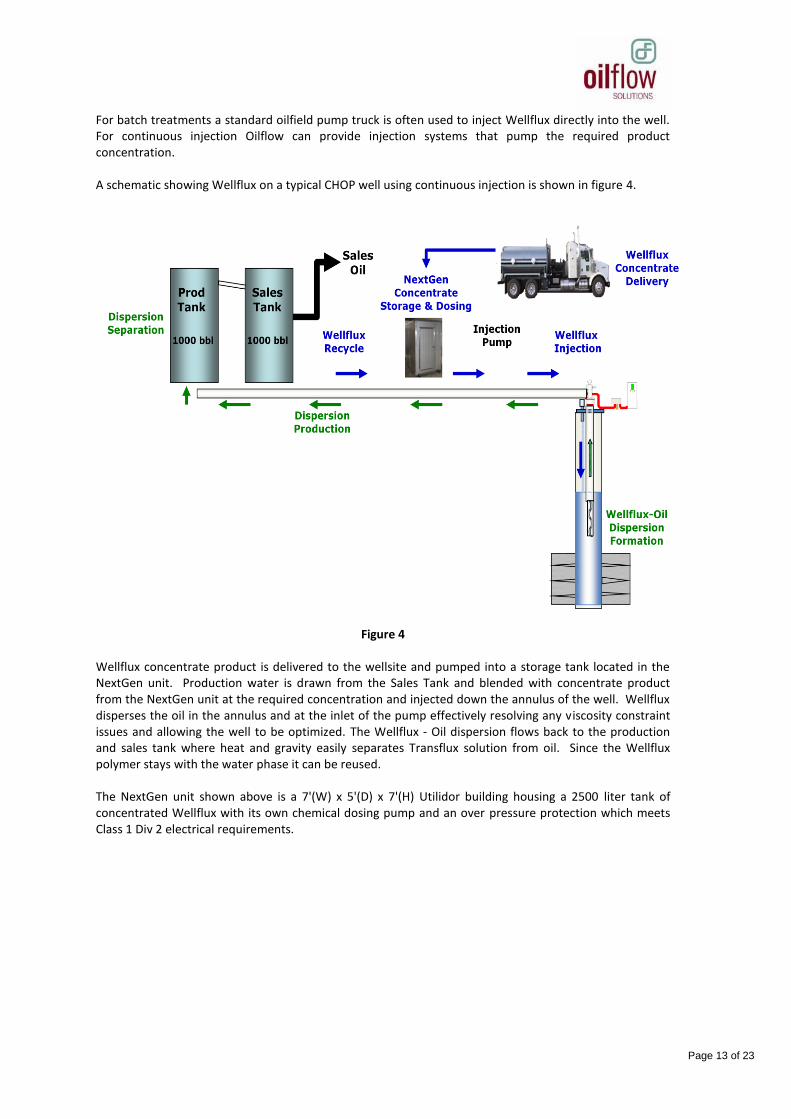
For batch treatments a standard oilfield pump truck is often used to inject Wellflux directly into the well. For continuous injection Oilflow can provide injection systems that pump the required product concentration. A schematic showing Wellflux on a typical CHOP well using continuous injection is shown in figure 4.
Figure 4 Wellflux concentrate product is delivered to the wellsite and pumped into a storage tank located in the NextGen unit. Production water is drawn from the Sales Tank and blended with concentrate product from the NextGen unit at the required concentration and injected down the annulus of the well. Wellflux disperses the oil in the annulus and at the inlet of the pump effectively resolving any viscosity constraint issues and allowing the well to be optimized. The Wellflux - Oil dispersion flows back to the production and sales tank where heat and gravity easily separates Transflux solution from oil. Since the Wellflux polymer stays with the water phase it can be reused. The NextGen unit shown above is a 7'(W) x 5'(D) x 7'(H) Utilidor building housing a 2500 liter tank of concentrated Wellflux with its own chemical dosing pump and an over pressure protection which meets Class 1 Div 2 electrical requirements.

Page 14 of 23
3 ENHANCED OIL RECOVERY APPLICATIONS
Enhanced Oil Recovery (EOR) applications utilize Terraflux products to increase oil production and improve recovery factor by injecting the polymer into reservoirs after primary production or as an enhancement to waterflooding. Terraflux utilizes a unique combination of wettability modification and IFT reduction that leads to improved oil mobility and enhances recovery and production. Terraflux Hybrid combines Terraflux with hydrolyzed polyachrylamide (HPAM) which provides the properties of Terraflux with the added advantage of viscosifying the water which creates a more efficient sweeping of the residual oil while minimizing viscous fingering. The result is an additional improvement in production and recovery factor. Figure 5 below demonstrates the system mechanism.
Figure 5
Terraflux and Terraflux Hybrid are being developed as an improvement to conventional Surfactant Polymer (SP) and Alkali-Surfactant-Polymer (ASP) floods. SP and ASP do achieve a reduction in Residual Oil Saturation (Sor), but they also brought to light other challenges. These challenges require significant investments to mitigate which include:
- Additional demulsifiers to break the tight emulsions created by surfactants. - High adsorption of surfactants in the reservoir which leads to higher chemical costs to
compensate for those loses. - Significant scale issues at the production end caused by the use of Alkali.
3.1 TERRAFLUX PROPERTIES AND CHARACTERISTICS
Oil producers require that injected EOR fluids are cost effective, simple to deploy and compatible with the reservoir and its fluids. Terraflux chemistry fulfills these requirements, exhibiting the following properties:

Page 15 of 23
- Terraflux polymers offer high salinity tolerance (>150,000 TDS and 15000 ppm of hardness ions
Ca2+
& Mg2+
). - Terraflux solutions are thermally stable up to 200
oC.
- Terraflux can be deployed with a surface storage tank and a dosing pump which minimizes
CAPEX.
- Unlike surfactants, Terraflux stays with the water when separated from oil. The water containing Terraflux can then be re-injected in the formation for added commercial benefit.
- Terraflux demonstrate low adsorption rates in comparison to conventional polymers and
surfactants.
- Terraflux polymers do not upset the production separation train and when subject to heat and gravity, the Terraflux oil in water dispersions are easily separated with Terraflux having the potential to be recycled from the separated water phase.
- Third party testing has confirmed that Terraflux is compatible with generic scale and corrosion inhibitors, demulsifiers and pump elastomers. Additionally, Terraflux has been further tested in various client management of change processes (MOC) thus allowing it to be easily incorporated into Canadian oilfield applications.
- In 3rd
party testing, Terraflux polymers demonstrate ultra low toxicity and biodegradability 3.2 TERRAFLUX DEVELOPMENT
Numerous studies have been completed to evaluate the performance of Terraflux as a standalone low cost polymer flooding solution. A sand-pack lab tests using a 21,850cP @ 25degC oil indicate a 40% increase in oil recover factor over waterflood (RF of 28% from water flood and 40% from water/Terraflux). Graph 1 below shows the results form a sand pack test when 3000 ppm of Terraflux solution was tested.
Graph 1
In April 2013, Oilflow started a pilot test for an augmented water flood (adding Terraflux to the injected water) for a major operator in Canada. The plan is to inject be 65 m
3/day of Terraflux at 0.3%
concentration and compare results versus adjacent water floods. The objectives of the pilot project are: - Increase production and enhance oil recovery versus conventional water flood.
0
5
10
15
20
25
30
35
40
45
50
0.0 0.5 1.0 1.5 2.0 2.5 3.0 3.5 4.0 4.5 5.0
Rec
ove
ry F
ac
tor
(%)
Pore Volume of Effluent
Terraflux
Waterflood

Page 16 of 23
- Maintain the project economics. The marginal production per well makes it hard to justify the CAPEX of a full scale viscosifying polymer injection system and the required water treatment.
- Book additional oil reserves in 2014.
3.3 TERRAFLUX HYBRID DEVELOPMENT
The performance of Terraflux Hybrid has been evaluated in multiple sand pack experiments. Graph 2 below is from a sand pack test using 3000 cP @ 25 decC heavy oil, oilfield brine, 30% porosity and a sand pack with a permeability of 9 Darcy. Table 5 below summarizes the results from this sand pack study.
Graph 2
Table 5
Water flood HPAM Terraflux Hybrid
Recovery Factor 26 % 38 % 45 %
Oilflow has been collaborating with the world’s largest hydrolyzed polyachrylamide (HPAM) manufacturer in proving and optimizing this technology. Two client funded core flood studies have been performed at the Oilflow R&D center in Calgary in preparation for two pilot tests in Q4 2013 in Canada. The first pilot test will be implemented in a field that is currently under an ASP flood. The main drivers for the client to explore the Terraflux-Hybrid technology are:
- Find a solution to the expensive major scale and corrosion issues caused by Alkali.

Page 17 of 23
- Poor oil-water separation at the production end caused by the tight emulsions created by surfactants.
- The chemical interaction of Alkali in the reservoir caused a significant change in reservoir pH,
which leads to temporarily shutting in part of the field.
3.4 R&D POROUS MEDIA LAB
Oilflow’s porous media laboratories contain state of the art equipment designed to accommodate a multitude of experimental projects that are performed by experienced professionals. Our Porous Media Lab has the capability to simultaneously perform both sandpack and core flood experiments. Sand pack geometries range from 30 cm length x 2.5 cm ID to 66 / 81.5 cm length x 4 cm ID. Industry-accepted methods for packing are used to ensure optimum reproducibility between comparative trials. We utilize cleaned silica sand with different mesh sizes to provide the desired permeability and porosity range. Core floods can be performed on either 2.5 cm (1”) or 3.8 cm (1.5”) diameter samples, cleaned commercial cores (e.g. Berea or Dundee sandstone) or client supplied cores from target reservoirs. To simulate reservoir conditions the cores are aged after oil saturation and an overburden pressures up to 2500 psi can be applied. Figure 6 is a picture of Oilflow’s porous media lab.
Figure: 6 OSI Porous media laboratory A list of key porous media equipment is shown in table 5 below.
Table 5
• Dual Cylinder Teledyne ISCO pump (10000 psi) • Dual Cylinder Quizzix Pump (6000 psi) with Pumpworks Software • Stainless Steel Transfer Cylinders: • 4 x 1750 mL • 2 x 750 mL
• Stainless Steel Sandpacks : • 1 x 66 cm length x 4 cm ID • 1 x 81.5 cm length x 4 cm ID • 3 x 30 cm length x 2.5 cm ID • Stainless Steel Hassler Cell: • 1 x 15 cm length x 2.5 cm ID (5000 psi) • 2 x 25 cm length x 2.5/3.8 cm ID (5000 psi)
• Rosemount Pressure Transducers (2 x 2000 psi) • Temperature Controlled Ovens (x 3 of various sizes) • Dean-Stark Extraction Glassware • Buchi Rotary Evaporator • Robinson Centrifuge • Amott Cells (x 12) • HTS PAL Robotic Effluent Collectors (x 2)

Page 18 of 23
The accuracy of experimental procedures and measurements is critical to obtaining reliable data for the prediction of EOR performance. Over the last year, Oilflow labs have undergone an important refining of these techniques in order to guarantee higher test result accuracy whilst at the same time expanding its test capabilities. Dual cylinder ISCO and Quizix pumps are used to control injection flow rates when performing brine saturation, oil saturation and oil recovery experiments, while the pressure drop across the length of the core/sandpack is monitored using calibrated pressure transducers so that brine and oil permeabilities can be determined. Transfer cylinders are used to inject the appropriate fluids into the core / sandpack during critical displacement experiments, while the effluent fluid is fractionated by a robotic collector to account for oil, water and polymer recovered. Final fluid saturations are determined by Dean Stark analysis so as to provide a reference endpoint for the flood data collected and to close the material balance for amounts of oil recovered. Polymer effluent analysis is also performed to measure produced polymer concentrations. The entire core/sandpack experiments can be performed in an oven to simulate the actual reservoir temperature. All the data is processed and interpreted in-house by the Oilflow technical team and then utilized by our Senior Reservoir Engineer to history match production and pressure data. The history matched data is then utilized to upscale to EOR field applications. Oilflow uses CMG STARS reservoir simulator and CMOST tool to optimize injection strategies and maximize the net present value (NPV) of target EOR projects.
Page 19 of 23
4 TRANSPORT APPLICATIONS
Transport applications utilize Transflux products that enhance the mobility of heavy oil and bitumen in gathering, feeder and transmission pipe lines where viscosity hinders throughput. Transflux is used to enhance the mobility of heavy oil in gathering, feeder and transmission pipelines resulting in additional throughput versus diluents and at lower cost. Transflux Ultra performs the same function as Transflux but has been developed to transport bitumen.
When injected into a pipeline, Transflux and Transflux Ultra create a dispersion that reduces the apparent viscosity of the flowing fluids in the range of 100 to 1000cP. The dispersion that is created enhances the “slippage” of the oil droplets in the pipeline reducing the energy required to transport heavy oil and bitumen which enables additional through put. 4.1 TRANSFLUX PROPERTIES AND CHARACTERISTICS
- When the Transflux polymer solution is brought in contact with heavy oil a reduction in
interfacial tension (IFT) occurs between the oil and water phases allowing the formation of highly mobile low viscosity oil in water dispersion with apparent viscosities between 100 to 300 cP.
- When Transflux Ultra polymer solution is brought in contact with bitumen a mobile low viscosity
bitumen in water dispersion is formed with apparent viscosities between 500 to 1000 cP. - Transflux, unlike many surfactants, demonstrates low oil phase solubility and therefore oil and
water separation is rapid in conventional separation units allowing the Transflux solution to be recycled and reused.
- Independent third party testing has confirmed that Proflux is compatible with generic scale and
corrosion inhibitors, demulsifiers and pump elastomers. Additionally, the Transflux technology has been evaluated by numerous clients and has successfully under gone various management of change (MOC) processes, thus allowing it to be easily incorporated into Canadian oilfield applications.
- Transflux polymers are low molecular weight, non-ionic, water soluble polymers that have high
salinity tolerance (>150,000 TDS and >15,000 ppm of hardness ions Ca2+
& Mg2+
).
- Rapid solubilization of Transflux solutions up to 15 wt % can be achieved. The resulting concentrate can be rapidly diluted to afford a low viscosity (1 cP) field strength solution (3000 to 5000 ppm) using a variety of produced or source waters.
- Transflux polymers are not sensitive to mechanical shear degradation normally seen with high
molecular weight polymers.
- Transflux polymer solutions are thermally stable up to 200 oC further extending the application to
transport of high temperature heavy oil and bitumen.
- In 3rd
party testing, Transflux polymers demonstrate ultra low toxicity and biodegradability.
4.2 TRANSFLUX DEVELOPMENT
Numerous lab experiments have been completed for the purpose of evaluating the potential of the Transflux technology on a variety of heavy oils. Multiple experiments utilizing Oiflow’s flow loop suggest
Page 20 of 23
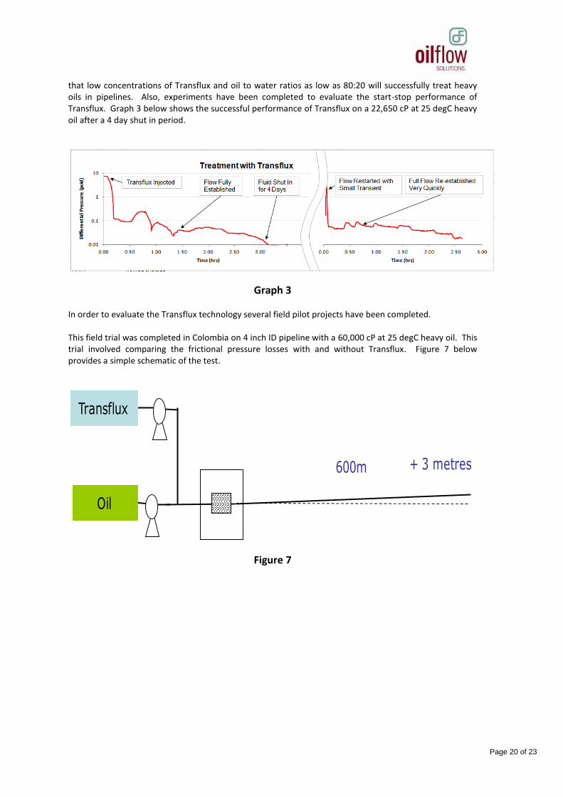
that low concentrations of Transflux and oil to water ratios as low as 80:20 will successfully treat heavy oils in pipelines. Also, experiments have been completed to evaluate the start-stop performance of Transflux. Graph 3 below shows the successful performance of Transflux on a 22,650 cP at 25 degC heavy oil after a 4 day shut in period.
Graph 3 In order to evaluate the Transflux technology several field pilot projects have been completed. This field trial was completed in Colombia on 4 inch ID pipeline with a 60,000 cP at 25 degC heavy oil. This trial involved comparing the frictional pressure losses with and without Transflux. Figure 7 below provides a simple schematic of the test.
Figure 7
+ 3 metres600m
Oil
Transflux

Page 21 of 23
Prior to treating with Transflux, neat untreated oil was first injected through the pipeline until a steady state injection pressure was achieved. The injection pressure was approximately 850psi, the differential pressure along the pipe was approximately 820psi and the residence time in the pipe was approximately 2 hours. Graph 3 shows the evolution of the fluid injection pressure as a Transflux solution (70:30 oil to Transflux ratio) was injected into the flow stream of the dry oil. Over a period of approximately 2 hours the injection pressure fell to around 25psi. This 98% reduction in injection pressure was achieved with a 40% increase in total fluid flow rate, demonstrating the potential to transport increased fluid with reduced energy.
Graph 4
0
100
200
300
400
500
600
700
800
900
1000
0 1 2 3 4
Inje
cti
on
Pre
ssu
re p
si
.
Trial Time hours
Begin Transf lux
Transf lux Dispersion Injection Pressure 25 psi
Oil Injection Pressure: 850 psi
Page 22 of 23
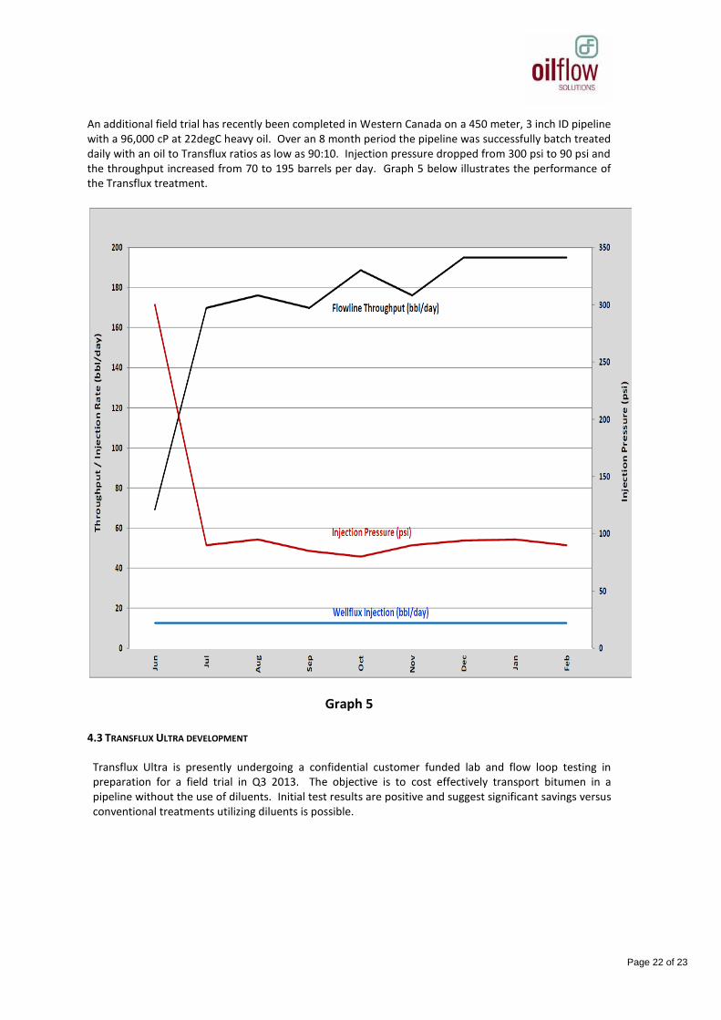
An additional field trial has recently been completed in Western Canada on a 450 meter, 3 inch ID pipeline with a 96,000 cP at 22degC heavy oil. Over an 8 month period the pipeline was successfully batch treated daily with an oil to Transflux ratios as low as 90:10. Injection pressure dropped from 300 psi to 90 psi and the throughput increased from 70 to 195 barrels per day. Graph 5 below illustrates the performance of the Transflux treatment.
Graph 5 4.3 TRANSFLUX ULTRA DEVELOPMENT
Transflux Ultra is presently undergoing a confidential customer funded lab and flow loop testing in preparation for a field trial in Q3 2013. The objective is to cost effectively transport bitumen in a pipeline without the use of diluents. Initial test results are positive and suggest significant savings versus conventional treatments utilizing diluents is possible.
Page 23 of 23
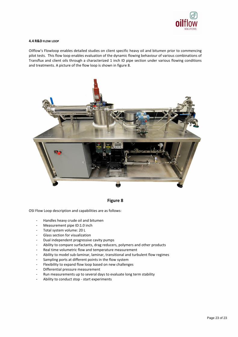
4.4 R&D FLOW LOOP
Oilflow’s Flowloop enables detailed studies on client specific heavy oil and bitumen prior to commencing pilot tests. This flow loop enables evaluation of the dynamic flowing behaviour of various combinations of Transflux and client oils through a characterized 1 inch ID pipe section under various flowing conditions and treatments. A picture of the flow loop is shown in figure 8.
Figure 8 OSI Flow Loop description and capabilities are as follows:
- Handles heavy crude oil and bitumen - Measurement pipe ID:1.0 inch - Total system volume: 20 L - Glass section for visualization - Dual independent progressive cavity pumps - Ability to compare surfactants, drag reducers, polymers and other products - Real time volumetric flow and temperature measurement - Ability to model sub-laminar, laminar, transitional and turbulent flow regimes - Sampling ports at different points in the flow system - Flexibility to expand flow loop based on new challenges - Differential pressure measurement - Run measurements up to several days to evaluate long term stability - Ability to conduct stop - start experiments