Overview of OBD I & II ST060 Introduction
15
OBD II Intro - 2 Overview of On-Board Diagnostics (OBD I & II), • In continuing efforts to improve air quality, the Environmental Protection Agency (EPA) amended the Clean Air Act in 1990. The Clean Air Act was originally mandated in 1970. The Clean Air Act has a direct impact on automobile manufactures whereby they are responsible to comply with the regulations set forth by the EPA. The 1990 amendment of the Clean Air Act set forth all of the changes currently being introduced on vehicles sold in the United States today. • In 1967, the State of California formed the California Air Resources Board (CARB) to develop and carryout air quality improvement programs for California’s unique air pollu- tion conditions. Through the years, CARB programs have evolved into what we now know as ON Board Diagnostics (OBD) and the National Low Emission Vehicle Program. • The EPA has adopted many of the CARB programs as National programs and laws. One of these earlier programs was OBD I and the introduction of the “CHECK ENGINE” Light. • BMW first introduced OBD I and the check engine light in the 1987 model year. This enhanced diagnosis through the display of “flash codes” using the check engine light as well as the BMW 2013 and MoDiC. OBD I was only the first step in an ongoing effort to monitor and reduce tailpipe emissions. • By the 1989 model year all automotive manufactures had to assure that all individual components influencing the composition of exhaust emissions would be electrically monitored and that the driver be informed whenever such a component failed. • Since the 1996 model year all vehicles must comply with OBD II requirements. OBD II requires the monitoring of virtually every component that can affect the emission per- formance of a vehicle plus store the associated fault code and condition in memory. If a problem is detected and then re-detected during a later drive cycle more than one time, the OBD II system must also illuminate the Check Engine Light in the instrument cluster to alert the driver that a malfunction has occurred. However, the flash code func- tion of the Check Engine Light in OBD I vehicles is not a function in OBD II vehicles. • This requirement is carried out by the Engine Control Module (ECM/DME) as well as the Automatic Transmission Control Module (EGS/AGS) and the Electronic Throttle Control Module (EML) to monitor and store faults associated with all components/systems that can influence exhaust and evaporative emissions. CHECK ENGINE
Transcript of Overview of OBD I & II ST060 Introduction
OBD II Intro - 2
Overview of On-Board Diagnostics (OBD I & II),
• In continuing efforts to improve air quality, the Environmental Protection Agency (EPA)amended the Clean Air Act in 1990. The Clean Air Act was originally mandated in 1970.The Clean Air Act has a direct impact on automobile manufactures whereby they areresponsible to comply with the regulations set forth by the EPA. The 1990 amendmentof the Clean Air Act set forth all of the changes currently being introduced on vehiclessold in the United States today.
• In 1967, the State of California formed the California Air Resources Board (CARB) todevelop and carryout air quality improvement programs for California’s unique air pollu-tion conditions. Through the years, CARB programs have evolved into what we nowknow as ON Board Diagnostics (OBD) and the National Low Emission Vehicle Program.
• The EPA has adopted many of the CARB programs as National programs and laws.One of these earlier programs was OBD I and the introduction of the “CHECK ENGINE”Light.
• BMW first introduced OBD I and the check engine light in the 1987model year. This enhanced diagnosis through the display of “flashcodes” using the check engine light as well as the BMW 2013 andMoDiC. OBD I was only the first step in an ongoing effort to monitorand reduce tailpipe emissions.
• By the 1989 model year all automotive manufactures had to assure that all individualcomponents influencing the composition of exhaust emissions would be electricallymonitored and that the driver be informed whenever such a component failed.
• Since the 1996 model year all vehicles must comply with OBD II requirements. OBD IIrequires the monitoring of virtually every component that can affect the emission per-formance of a vehicle plus store the associated fault code and condition in memory.
If a problem is detected and then re-detected during a later drive cycle more than onetime, the OBD II system must also illuminate the Check Engine Light in the instrumentcluster to alert the driver that a malfunction has occurred. However, the flash code func-tion of the Check Engine Light in OBD I vehicles is not a function in OBD II vehicles.
• This requirement is carried out by the Engine Control Module (ECM/DME) as well as theAutomatic Transmission Control Module (EGS/AGS) and the Electronic Throttle ControlModule (EML) to monitor and store faults associated with all components/systems thatcan influence exhaust and evaporative emissions.
CCHHEECCKKEENNGGIINNEE
OBD II Intro - 3
Overview of the National Low Emission VehicleProgram
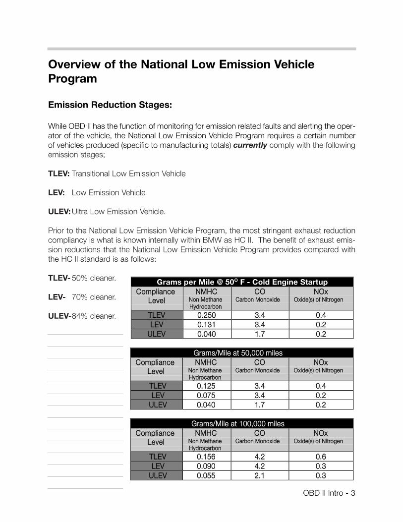
Emission Reduction Stages:
While OBD II has the function of monitoring for emission related faults and alerting the oper-ator of the vehicle, the National Low Emission Vehicle Program requires a certain numberof vehicles produced (specific to manufacturing totals) currently comply with the followingemission stages;
TLEV: Transitional Low Emission Vehicle
LEV: Low Emission Vehicle
ULEV: Ultra Low Emission Vehicle.
Prior to the National Low Emission Vehicle Program, the most stringent exhaust reductioncompliancy is what is known internally within BMW as HC II. The benefit of exhaust emis-sion reductions that the National Low Emission Vehicle Program provides compared withthe HC II standard is as follows:
TLEV- 50% cleaner.
LEV- 70% cleaner.
ULEV-84% cleaner.
Grams per Mile @ 50O F - Cold Engine StartupCCoommpplliiaannccee
LLeevveellNNMMHHCC
NNoonn MMeetthhaanneeHHyyddrrooccaarrbboonn
CCOOCCaarrbboonn MMoonnooxxiiddee
NNOOxxOOxxiiddee((ss)) ooff NNiittrrooggeenn
TTLLEEVV 00..225500 33..44 00..44LLEEVV 00..113311 33..44 00..22
UULLEEVV 00..004400 11..77 00..22
GGrraammss//MMiillee aatt 5500,,000000 mmiilleessCCoommpplliiaannccee
LLeevveellNNMMHHCC
NNoonn MMeetthhaanneeHHyyddrrooccaarrbboonn
CCOOCCaarrbboonn MMoonnooxxiiddee
NNOOxxOOxxiiddee((ss)) ooff NNiittrrooggeenn
TTLLEEVV 00..112255 33..44 00..44 LLEEVV 00..007755 33..44 00..22
UULLEEVV 00..004400 11..77 00..22
GGrraammss//MMiillee aatt 110000,,000000 mmiilleessCCoommpplliiaannccee
LLeevveellNNMMHHCC
NNoonn MMeetthhaanneeHHyyddrrooccaarrbboonn
CCOOCCaarrbboonn MMoonnooxxiiddee
NNOOxxOOxxiiddee((ss)) ooff NNiittrrooggeenn
TTLLEEVV 00..115566 44..22 00..66 LLEEVV 00..009900 44..22 00..33
UULLEEVV 00..005555 22..11 00..33
OBD II Intro - 4
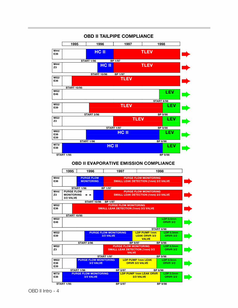
OBD II EVAPORATIVE EMISSION COMPLIANCE
1995 1996 1997 1998
M44/E36 HC II TLEV ➨
START 1/96 BP 1/97M44/Z3 HC II TLEV ➨
START 10/96 BP 1/97M52/E36 TLEV ➨
START 10/95M52/E46 LEV ➨
START 6/98M52/E39 TLEV LEV ➨
START 3/96 BP 9/98M52/Z3 TLEV LEV ➨
START 1/97 BP 9/98M62/E38E39
HC II LEV ➨START 1/96 BP 6/98
M73/E38 HC II LEV ➨
START 1/95 BP 9/98
OBD II EVAPORATIVE EMISSION COMPLIANCE
1995 1996 1997 1998
M44/E36
PURGE FLOWMONITORING
PURGE FLOW MONITORINGSMALL LEAK DETECTION (1mm) 3/2 VALVE ➨
START 1/96 BP 1/97M44/Z3
PURGE FLOWMONITORING ➨ ➨
3/2 VALVE
PURGE FLOW MONITORINGSMALL LEAK DETECTION (1mm) 3/2 VALVE ➨
START 10/96 BP 1/97M52/E36
PURGE FLOW MONITORINGSMALL LEAK DETECTION (1mm) 3/2 VALVE ➨
START 10/95M52/E46
LDP 0.5mmORVR 3/2 ➨
START 6/98M52/E39
PURGE FLOW MONITORING 3/2 VALVE
LDP PUMP 1mmLEAK ORVR 3/2
VALVE
LDP 0.5mmORVR 3/2 ➨
START 3/96 BP 9/97 BP 9/98M52/Z3
PURGE FLOW MONITORING SMALL LEAK DETECTION (1mm) 3/2
VALVE
LDP 0.5mmORVR 3/2 ➨
START 1/97 BP 9/98M62/E38E39
PURGE FLOW MONITORING3/2 VALVE
LDP PUMP 1mm LEAKORVR 3/2 VALVE
LDP 0.5mmORVR 3/2 ➨
START 1/96 BP 5/97 BP 6/98M73/E38
PURGE FLOW MONITORING 3/2 VALVE
LDP PUMP 1mm LEAK ORVR3/2 VALVE
LDP 0.5mmORVR 3/2 ➨
START 1/95 BP 5/97 BP 9/98
OBD II TAILPIPE COMPLIANCE
OBD II Drive Cycle’s & Trips
As defined within CARB mail-out 1968.1:
• A "Drive cycle" consists of engine startup, vehicle operation and engine shutoff.
• "Trip" is defined as vehicle operation (following an engine-off period) of duration and dri-ving style so that all components and systems are monitored at least once by the diag-nostic system except catalyst efficiency or evaporative system monitoring.
This definition is subject to the limitations that the manufacturer-defined trip monitoringconditions are all monitored at least once during the first engine start portion of theFederal Test Procedure (FTP).
• Within this text the term "customer driving cycle" will be used and is defined asengine start-up, operation of vehicle (dependent upon customer drive style) and engineshut-off.
OBD II Intro - 5
Federal Test Procedure (FTP)
The Federal Test Procedure (FTP) is a specific driving cycle that is utilized by the EPA totest light duty vehicles and light duty truck emissions. As part of the procedure for a vehi-cle manufacturer to obtain emission certification for a particular model/engine family themanufacturer must demonstrate that the vehicle(s) can pass the FTP defined driving cycletwo consecutive times while monitoring various components/systems.
Some of the components/systems must be monitored either once per driving cycle orcontinuously.
Systems and their components required to be monitored once within one driving cycle:
• Oxygen Sensors
• Secondary Air Injection System
• Catalyst Efficiency
• Evaporative Vapor Recovery System
Due to the complexity involved in meeting the test criteria within the FTP defineddriving cycle, all tests may not be completed within one "customer driving cycle".The test can be successfully completed within the FTP defined criteria, howevercustomer driving styles may differ and therefore may not always monitor allinvolved components/systems in one "trip".
Components/systems required to be monitored continuously:
• Cylinder Misfire Detection
• Fuel system
• Oxygen Sensors
• All emissions related components/systems providing or getting electrical connections to the DME, EGS, or EML (comprehensive component monitoring).
OBD II Intro - 6
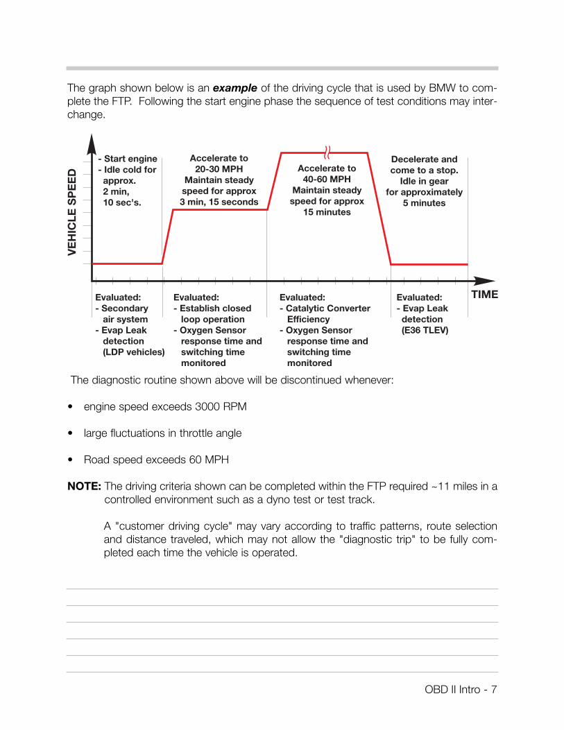
The graph shown below is an example of the driving cycle that is used by BMW to com-plete the FTP. Following the start engine phase the sequence of test conditions may inter-change.
The diagnostic routine shown above will be discontinued whenever:
• engine speed exceeds 3000 RPM
• large fluctuations in throttle angle
• Road speed exceeds 60 MPH
NOTE: The driving criteria shown can be completed within the FTP required ~11 miles in acontrolled environment such as a dyno test or test track.
A "customer driving cycle" may vary according to traffic patterns, route selectionand distance traveled, which may not allow the "diagnostic trip" to be fully com-pleted each time the vehicle is operated.
OBD II Intro - 7
"CHECK ENGINE" Light (MIL)
In conjunction with the CARB/OBD II regulations the "CHECK ENGINE"light (also referred to as the Malfunction Indicator Light - MIL) is to be illu-minated under the following conditions:
• Upon the completion of the next consecutive driving cycle where the previously fault-ed system is monitored again and the emissions relevant fault is again present.
• Immediately if a catalyst damaging fault occurs (see Misfire Detection).
The illumination of the check engine light is performed in accordance with the Federal TestProcedure (FTP) which requires the lamp to be illuminated when:
• A malfunction of a component that can affect the emission performance of the vehicleoccurs and causes emissions to exceed 1.5 times the standards required by the (FTP).
• Manufacturer-defined specifications are exceeded.
• An implausible input signal is generated.
• Catalyst deterioration causes HC-emissions to exceed a limit equivalent to 1.5 times thestandard (FTP).
• Misfire faults occur.
• A leak is detected in the evaporative system
• The oxygen sensors observe no purge flow from the purge valve/evaporative system.
• Engine control module fails to enter closed-loop operation within a specified time interval.
• Engine control or automatic transmission control enters a "limp home" operating mode.
• Key is in the "ignition" on position before cranking (Bulb Check Function).
Within the BMW system the illumination of the check engine light is performed in accor-dance with the regulations set forth in CARB mail-out 1968.1 and as demonstrated via theFederal Test Procedure (FTP).
The following information provides several examples of when and how the "Check Engine"Light is illuminated based on the "customer drive cycle".
OBD II Intro - 8
CCHHEECCKKEENNGGIINNEE
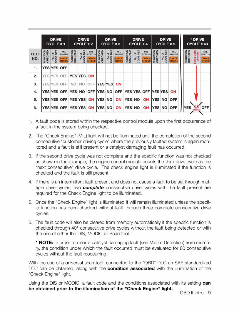
1. A fault code is stored within the respective control module upon the first occurrence ofa fault in the system being checked.
2. The "Check Engine" (MIL) light will not be illuminated until the completion of the secondconsecutive "customer driving cycle" where the previously faulted system is again mon-itored and a fault is still present or a catalyst damaging fault has occurred.
3. If the second drive cycle was not complete and the specific function was not checkedas shown in the example, the engine control module counts the third drive cycle as the“next consecutive“ drive cycle. The check engine light is illuminated if the function ischecked and the fault is still present.
4. If there is an intermittent fault present and does not cause a fault to be set through mul-tiple drive cycles, two complete consecutive drive cycles with the fault present arerequired for the Check Engine light to be illuminated.
5. Once the "Check Engine" light is illuminated it will remain illuminated unless the specif-ic function has been checked without fault through three complete consecutive drivecycles.
6. The fault code will also be cleared from memory automatically if the specific function ischecked through 40* consecutive drive cycles without the fault being detected or withthe use of either the DIS, MODIC or Scan tool.
* NOTE: In order to clear a catalyst damaging fault (see Misfire Detection) from memo-ry, the condition under which the fault occurred must be evaluated for 80 consecutivecycles without the fault reoccurring.
With the use of a universal scan tool, connected to the "OBD" DLC an SAE standardizedDTC can be obtained, along with the condition associated with the illumination of the"Check Engine" light.
Using the DIS or MODIC, a fault code and the conditions associated with its setting canbe obtained prior to the illumination of the "Check Engine" light.
OBD II Intro - 9
Readiness Code
CARB/EPA Requirement:
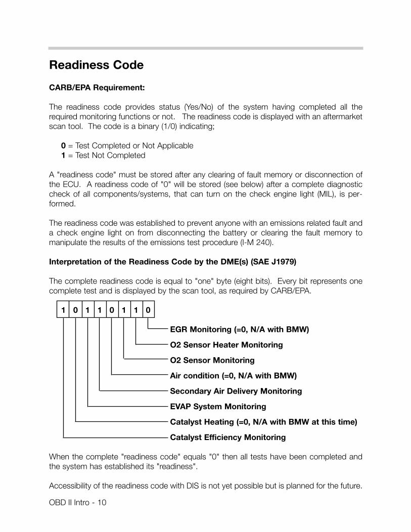
The readiness code provides status (Yes/No) of the system having completed all therequired monitoring functions or not. The readiness code is displayed with an aftermarketscan tool. The code is a binary (1/0) indicating;
0 = Test Completed or Not Applicable1 = Test Not Completed
A "readiness code" must be stored after any clearing of fault memory or disconnection ofthe ECU. A readiness code of "0" will be stored (see below) after a complete diagnosticcheck of all components/systems, that can turn on the check engine light (MIL), is per-formed.
The readiness code was established to prevent anyone with an emissions related fault anda check engine light on from disconnecting the battery or clearing the fault memory tomanipulate the results of the emissions test procedure (I-M 240).
Interpretation of the Readiness Code by the DME(s) (SAE J1979)
The complete readiness code is equal to "one" byte (eight bits). Every bit represents onecomplete test and is displayed by the scan tool, as required by CARB/EPA.
1 0 1 1 0 1 1 0
EGR Monitoring (=0, N/A with BMW)
O2 Sensor Heater Monitoring
O2 Sensor Monitoring
Air condition (=0, N/A with BMW)
Secondary Air Delivery Monitoring
EVAP System Monitoring
Catalyst Heating (=0, N/A with BMW at this time)
Catalyst Efficiency Monitoring
When the complete "readiness code" equals "0" then all tests have been completed andthe system has established its "readiness".
Accessibility of the readiness code with DIS is not yet possible but is planned for the future.
OBD II Intro - 10
Establishment of System Readiness
1. Drive the car in such a manner that all tests listed above can be completed (refer to theFTP cycle).
2. In the future a DIS test module will be created to establish system readiness for most ofthe tests through a single operation. Currently only a partial list of "OBD" related com-ponents can be activated via the DIS - Test Modules/Component Activation.
This function for system readiness is only of use if a customer is subject to an I-M 240test and the readiness code(s) are not set as a result of a previous repair for the follow-ing:
• Secondary Air system
• Leak diagnosis
• Tank Venting valve
OBD II Intro - 11
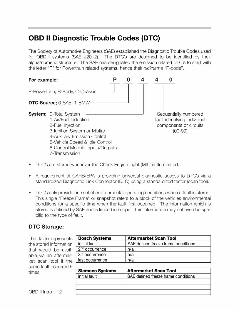
OBD II Diagnostic Trouble Codes (DTC)
The Society of Automotive Engineers (SAE) established the Diagnostic Trouble Codes usedfor OBD II systems (SAE J2012). The DTC’s are designed to be identified by theiralpha/numeric structure. The SAE has designated the emission related DTC’s to start withthe letter “P” for Powertrain related systems, hence their nickname “P-code”.
For example: P 0 4 4 0
P-Powertrain, B-Body, C-Chassis
DTC Source; 0-SAE, 1-BMW
System; 0-Total System1-Air/Fuel Induction2-Fuel Injection3-Ignition System or Misfire4-Auxiliary Emission Control5-Vehicle Speed & Idle Control6-Control Module Inputs/Outputs7-Transmission
• DTC’s are stored whenever the Check Engine Light (MIL) is illuminated.
• A requirement of CARB/EPA is providing universal diagnostic access to DTC’s via astandardized Diagnostic Link Connector (DLC) using a standardized tester (scan tool).
• DTC’s only provide one set of environmental operating conditions when a fault is stored.This single "Freeze Frame" or snapshot refers to a block of the vehicles environmentalconditions for a specific time when the fault first occurred. The information which isstored is defined by SAE and is limited in scope. This information may not even be spe-cific to the type of fault.
DTC Storage:
The table representsthe stored informationthat would be avail-able via an aftermar-ket scan tool if thesame fault occurred 5times.
OBD II Intro - 12
BBoosscchh SSyysstteemmss AAfftteerrmmaarrkkeett SSccaann TTooooll iinniittiiaall ffaauulltt SSAAEE ddeeffiinneedd ffrreeeezzee ffrraammee ccoonnddiittiioonnss 22nndd ooccccuurrrreennccee nn//aa 33rrdd ooccccuurrrreennccee nn//aa llaasstt ooccccuurrrreennccee nn//aa
SSiieemmeennss SSyysstteemmss AAfftteerrmmaarrkkeett SSccaann TTooooll iinniittiiaall ffaauulltt SSAAEE ddeeffiinneedd ffrreeeezzee ffrraammee ccoonnddiittiioonnss
Sequentially numberedfault identifying individualcomponents or circuits
(00-99)
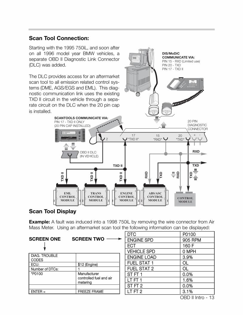
Scan Tool Connection:
Starting with the 1995 750iL, and soon afteron all 1996 model year BMW vehicles, aseparate OBD II Diagnostic Link Connector(DLC) was added.
The DLC provides access for an aftermarketscan tool to all emission related control sys-tems (DME, AGS/EGS and EML). This diag-nostic communication link uses the existingTXD II circuit in the vehicle through a sepa-rate circuit on the DLC when the 20 pin capis installed.
Scan Tool Display
Example: A fault was induced into a 1998 750iL by removing the wire connector from AirMass Meter. Using an aftermarket scan tool the following information can be displayed:
SCREEN ONE SCREEN TWO
OBD II Intro - 13
DDIIAAGG.. TTRROOUUBBLLEECCOODDEESSEECCUU:: $$1122 ((EEnnggiinnee))NNuummbbeerr ooff DDTTCCss:: 11**PP00110000 MMaannuuffaaccttuurreerr
ccoonnttrroolllleedd ffuueell aanndd aaiirrmmeetteerriinngg
EENNTTEERR == FFRREEEEZZEE FFRRAAMMEE
DDTTCC PP00110000EENNGGIINNEE SSPPDD 990055 RRPPMMEECCTT 116600 FFVVEEHHIICCLLEE SSPPDD 00 MMPPHHEENNGGIINNEE LLOOAADD 33..99%%FFUUEELL SSTTAATT 11 OOLLFFUUEELL SSTTAATT 22 OOLLSSTT FFTT 11 00..00%%LLTT FFTT 11 11..66%%SSTT FFTT 22 00..00%%LLTT FFTT 22 33..11%%
OBD II Intro - 14
BMW Fault Code (DIS/MoDiC)
• BMW Codes are stored as soon they occur even before the Check Engine Light (MIL)comes on.
• BMW Codes are defined by BMW, Bosch, and Siemens Engineers to provide greaterdetail to fault specific information.
• Siemens systems - (1) set of (4) fault specific environmental conditions are stored withthe first fault occurrence. This information can change and is specific to each fault codeto aid in diagnosing. A maximum of (10) different faults containing (4) environmental con-ditions can be stored.
• Bosch systems - a maximum of (4) sets of (3) fault specific environmental conditions arestored within each fault code. This information can change and is specific to each faultcode to aid in diagnosing. A maximum of (10) different faults containing (3) environ-mental conditions can be stored.
• BMW Codes also store and displays a "time stamp" when the fault last occurred.
• A fault qualifier gives more specific detailed information about the type of fault (upperlimit, lower limit, disconnection, plausibility, etc.).
• BMW Fault Codes will alert the technician of the current fault status. He will be advisedif the fault is actually still present, not currently present or intermittent. The fault specif-ic information is stored and accessible through DIS or Modic.
• BMW Fault Codes determine the diagnostic output for BMW DIS and Modic.
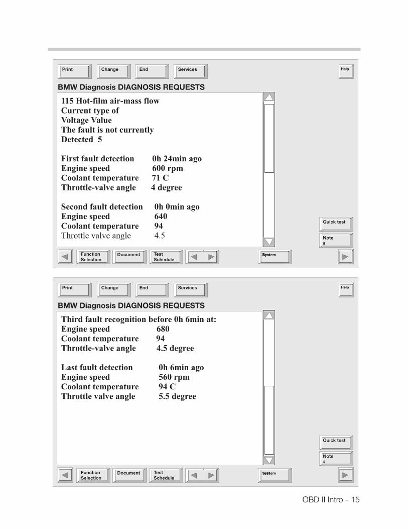
BMW Fault Code Storage:
The table below represents the information that would be available via the DIS tester if thesame fault occurred 5 times.
Bosch Systems DIS Tester Informationinitial fault 3 fault specific environmental conditions with time stamp,
counter, and if fault is currently present or intermittent2nd occurrence 3 fault specific environmental conditions with time stamp,
counter, and if fault is currently present or intermittent3rd occurrence 3 fault specific environmental conditions with time stamp,
counter, and if fault is currently present or intermittentlast occurrence 3 fault specific environmental conditions with time stamp,
counter, and if fault is currently present or intermittentSiemens Systems DIS Tester Informationinitial fault 4 fault specific environmental conditions with time stamp,
counter, and if fault is currently present or intermittent
OBD II Intro - 15
Emission Control Function Monitoring &Comprehensive Component Monitoring
OBD II regulations are based on section 1968.1 of Title 13, California Code of Regulations(CCR), The law set forth in section 1968.1 requires an increased scope of monitoring emis-sion related control functions including:
• Catalyst Monitoring • Heated Catalyst Monitoring (not currently used on BMW vehicles)• Misfire Monitoring• Evaporative System Monitoring• Secondary Air System Monitoring• Air Conditioning System Refrigerant Monitoring (Not applicable for BMW vehicles)• Fuel System Monitoring• Oxygen Sensor Monitoring• Exhaust Gas Recirculation (EGR) System Monitoring (Not applicable for BMW vehicles)• Positive Crankcase Ventilation (PCV) System Monitoring (Not required at this time).• Thermostat Monitoring (Not required at this time)
Monitoring these emission requirements is a function of the engine control module whichuses “data sets” while monitoring the conditions of the environment and the operation ofthe engine using existing input sensors and output actuators.
The data sets are programmed reference values the engine control module refers to whena specific monitoring procedure is occurring. If the control module cannot determine theenvironmental and/or engine operating conditions due to an impaired or missing signal, itwill set a fault and illuminate the Check Engine Light as described on page 9.
This input or control signal monitoring falls under another category called“Comprehensive Component Monitoring”.
The control module must recognize the loss or impairment of the signal or component. Itdetermines a faulted signal or sensor via three conditions:
1. Signal or component shorted to ground.2. Signal or component shorted to B+.3. Signal or component lost (open circuit).
Specific fault codes are used to alert the diagnostician of these conditions.
OBD II Intro - 16


![Autodiagnostico Obd y Obd II[1]](https://static.fdocuments.in/doc/165x107/563db847550346aa9a9238aa/autodiagnostico-obd-y-obd-ii1.jpg)