Overview of HWRF Modeling System - · PDF fileOverview of HWRF Modeling System Vijay...
38
1 Overview of HWRF Modeling System Vijay Tallapragada EMC/NCEP/NOAA Acknowledgements: HWRF Team Members at EMC, HRD/AOML, DTC, GFDL and URI WRF for Hurricanes Tutorial, Boulder, CO 27 th April, 2011
Transcript of Overview of HWRF Modeling System - · PDF fileOverview of HWRF Modeling System Vijay...
1
Overview of HWRF Modeling System
Vijay Tallapragada
EMC/NCEP/NOAA
Acknowledgements: HWRF Team Members at EMC, HRD/AOML, DTC, GFDL and URI
WRF for Hurricanes Tutorial, Boulder, CO
27th April, 2011

Outline
• Overview of the operational coupled HWRF System
• Components of the HWRF Model• HWRF Dynamics (specific to movable nested grid and
coupling)
• HWRF Physics
• Vortex Initialization and GSI
• Coupler and POM TC
• Postprocessing and vortex tracker
2

Hurricane WRF (HWRF)• The Weather Research and Forecast Modeling System for Hurricanes (HWRF) was
designed to address the Nation’s next generation hurricane forecast problems.
• HWRF was developed at NCEP/EMC utilizing the WRF software infrastructure.
• HWRF became operational in the year 2007 preceded by extensive testing and evaluation
for three hurricane seasons (2004-2006), and has been constantly improved to increase
the forecast skill for track, intensity and structure of Atlantic and Eastern Pacific
hurricanes.
• Starting with 2011 hurricane season, the operational coupled HWRF-POM modeling
system is based on a configuration of the general WRF code (V3.3). The use of same
code by research and operations is expected to facilitate and accelerate O2R and R2O.
3

Pre-implementation testing Initial implementation (2007)
Atlantic Track Stats, 2008 Atlantic Track Stats, 2009
4
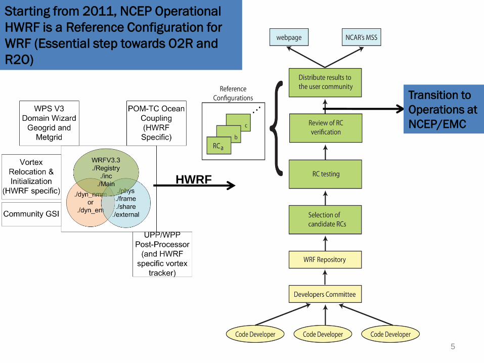
Starting from 2011, NCEP Operational
HWRF is a Reference Configuration for
WRF (Essential step towards O2R and
R2O)
Transition to
Operations at
NCEP/EMC
HWRF
5

WRF V3.2*
WRF V3.1.1
WRF V3.1
WRF V3.0
WRF V2.2
WRF V2.1
WRF V205/2004
07/2009
04/2010
08/2005
12/2006
04/2008
04/2009
FY2011 Operational HWRF Baseline Configuration
HWRF operational configuration (2011)
Extensive Testing (pre implementation)
WRF Repository (hosted by DTC)
HWRF2007
HWRF2008
HWRF2009
HWRF2010
WRF V3.3*05/2011
upgrades2011
•Modified vortex initialization (storm size correction and balanced vortex)•New GFS Deep Convection•Modified Surface Physics, Radiation and Microphysics•Community GSI
Extensive Testing (individual upgrades)
Regional Hurricane Model Development at EMC*Evaluation Completed 6

7
Benchmarking HWRFV3.2 (Atlantic 2008-2009-2010)
HWRFV3.2 produced nearly identical results compared to operational 2010 HWRF in the Atlantic

8
Benchmarking HWRFV3.2 (Eastern Pacific, 2008-2009-2010)
HWRFV3.2 produced very similar results compared to operational 2010 HWRF in the Eastern Pacific (except at 120hr forecast time)

9
Significant improvements
in track errors Reduced East-West Bias
Higher superior performance
2011 HWRF
10-12% improvement compared
to operational HWRF
% e
rro
r re
lati
ve
to
OC
D5

10
Improvements in intensity
errors
Improved intensity bias
20-25% error reduction in
the first 12-hrs
2011 HWRF
Improved Standard Deviation
% e
rro
r re
lati
ve
to
OC
D5

The HWRF Modeling System Regional-scale, moving nest, Ocean-Atmosphere coupled modeling system specially designed to
advance hurricane forecasts.
Makes use of WRF infrastructure for computational efficiency
Non-hydrostatic system of equations
rotated latitude-longitude, Arakawa E-grid
vertical pressure hybrid (sigma-P) coordinate.
NMM dynamics modified for inclusion of
movable nested grid, coupling to ocean model (POM-TC)
HWRF vortex initialization includes
vortex relocation, correction to winds, MSLP, temperature and moisture in the hurricane region
adjustment to actual storm size and intensity
assimilation of conventional observations and clear-sky radiance datasets using community GSI
Physical parameterization schemes designed and tested for tropical purposes
Ocean coupled modeling system (POM-TC of URI).
11

Flow Diagram for HWRF Coupled Modeling System
12

Outer (Parent) 216X432 0.18O (~27 km), 42 levels
Inner (Movable Nest)
60x100, 0.06o (~9 km)
Atmospheric domain
about 75o x 75o
POM-TC United domain
1/6o horizontal, 23 levels
13

Components of HWRF Modeling system
• WRF Pre-processing System (WPS)– Domain Specification and grid selection– Interpolation of GFS forecast (grib files) to generate real data
• WRF Model (HWRF dynamical core and HWRF Physics)– Initialization programs for real (real.exe – same as NMM
dynamical core)– Numerical integration program (wrf.exe)
• HWRF Initialization Software• Ocean Initialization, Ocean Model and Coupler• Post-Processing Program (WPP/UPO)• Vortex tracker• Graphical utilities for both HWRF and POM
14

WPS and real_nmm
• Running WPS– Several executable stages with namelist input
• geogrid.exe (interpolate maps and time-independent fields)• ungrib.exe (convert time-dependent Grib-formatted data to simple
binary format)• metgrid.exe (interpolate time-dependent initial and boundary data)
• Must chose a pre-determined configuration for both parent and nested domains.
• Outer domain (0.18 deg. Resolution – approx. 27 km; grid size: 216x432) and inner nest centered on storm location information obtained from tcvitals (0.06 deg. Resolution, approx. 9 km; grid size: 60x100)
• real_nmm.exe sets up vertical model levels for three-dimensional model input and boundary conditions
15
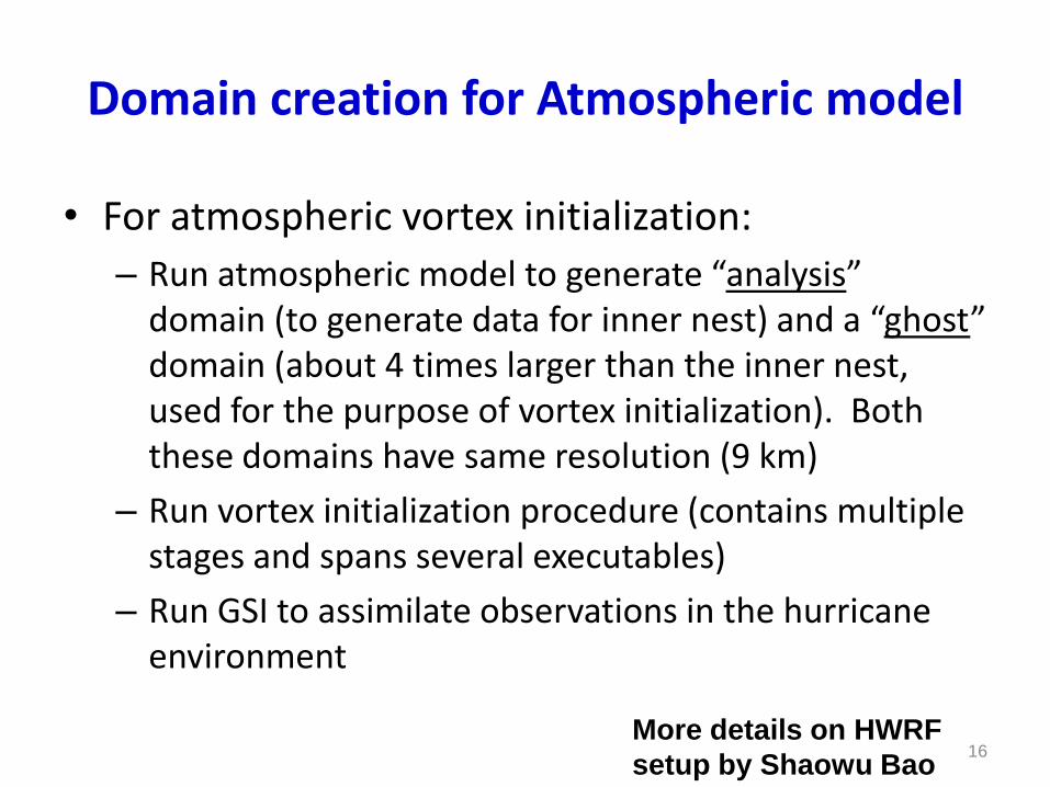
Domain creation for Atmospheric model
• For atmospheric vortex initialization:
– Run atmospheric model to generate “analysis” domain (to generate data for inner nest) and a “ghost” domain (about 4 times larger than the inner nest, used for the purpose of vortex initialization). Both these domains have same resolution (9 km)
– Run vortex initialization procedure (contains multiple stages and spans several executables)
– Run GSI to assimilate observations in the hurricane environment
More details on HWRF
setup by Shaowu Bao16
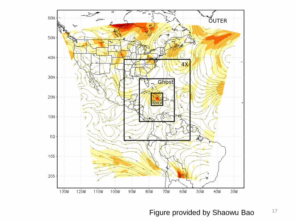
Figure provided by Shaowu Bao 17

HWRF Dynamics
• Modifications to WRF-NMM dynamic core specific to HWRF configurations include
– Vortex following two-way interactive movable nest
• Nest motion based on variations in dynamic pressure
• “Stagnation point” as the center of the storm
– Horizontal diffusion effect from TKE set to zero
– Solve_nmm.F modified to include insertions related to Coupler (send fluxes from atmosphere to ocean and pass SSTs from Ocean to atmosphere)
More details on HWRF
dynamics by Young Kwon18

• All interpolations are done on a rotated lat-lon, E-grid with the reference lat-lon located at the centre of the parent domain.
• Consequently the nested domain can be freely moved anywhere within the grid points of the parent domain, yet the nested domain lat-lon lines will coincide with the lat-lon lines of the parent domain at integral parent-to-nest ratio.
• This coincidence of grid points eliminates the need for more complex, generalized remapping calculations in the WRF Framework.
• Because of the E-grid structure and the fact that the input interface is well separated from dynamic interface, boundaries are updated at every time step of parent domain similar to how parent domain is updated at the mass point from the external data source (bc’s) .
Details specific
to nested grid
computations
More details on nesting
by Xuejin Zhang19

HWRF Physics
• HWRF model consists of advanced physical parameterization schemes adopted from GFS model and used by the highly successful GFDL hurricane model.
• Modified SAS convection scheme, Modified GFDL surface physics, GFS/GFDL planetary boundary layer physics, GFDL slab LSM, GFDL/GFS radiation and Ferrier Microphysical Scheme.
More details on HWRF
Physics by Bob Tuleya20

HWRF vortex initialization
• HWRF model uses an advanced vortex initialization procedure to represent model’s initial storm location, intensity and structure based on observed estimates provided by NHC.
• Coordinates of the observed position of the storm are used to relocate (correct) the storm’s initial location.
• A blend of synthetic vortex and storm perturbation from previous cycle’s 6-hr forecast (if available) are used to adjust (correct) storm’s initial, intensity and size to match the observed estimates.
21
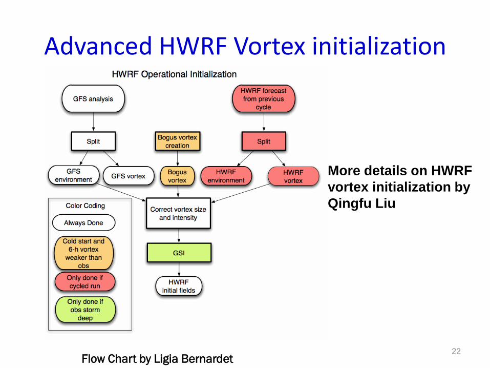
Advanced HWRF Vortex initialization
Flow Chart by Ligia Bernardet
More details on HWRF
vortex initialization by
Qingfu Liu
22
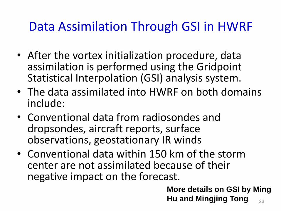
Data Assimilation Through GSI in HWRF
• After the vortex initialization procedure, data assimilation is performed using the GridpointStatistical Interpolation (GSI) analysis system.
• The data assimilated into HWRF on both domains include:
• Conventional data from radiosondes and dropsondes, aircraft reports, surface observations, geostationary IR winds
• Conventional data within 150 km of the storm center are not assimilated because of their negative impact on the forecast.
More details on GSI by Ming
Hu and Mingjing Tong 23

Princeton Ocean model for tropical cyclones (POM-TC)
• HWRF model is coupled to Princeton Ocean Model (POM) in the Atlantic to provide accurate SST fields as input to HWRF.
• POM model is driven by heat, radiative and momentum fluxes passed from HWRF and the SST response from POM is transferred back to HWRF.
• POM employs a sophisticated ocean initialization procedure to properly account for the cold wake generated by storm’s passage, and accurately represent gulf stream, warm and cold core eddies.
• A sophisticated “Coupler” was designed to enable exchange of information between the atmosphere and ocean during the model integration.
• Expanded Eastern Atlantic domain to prevent loss of ocean coupling for westward moving storms
24
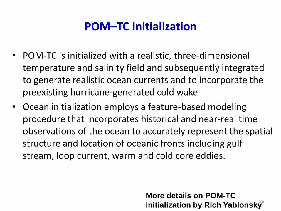
POM–TC Initialization
• POM-TC is initialized with a realistic, three-dimensional temperature and salinity field and subsequently integrated to generate realistic ocean currents and to incorporate the preexisting hurricane-generated cold wake
• Ocean initialization employs a feature-based modeling procedure that incorporates historical and near-real time observations of the ocean to accurately represent the spatial structure and location of oceanic fronts including gulf stream, loop current, warm and cold core eddies.
More details on POM-TC
initialization by Rich Yablonsky25
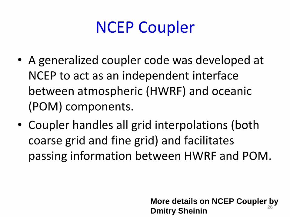
NCEP Coupler
• A generalized coupler code was developed at NCEP to act as an independent interface between atmospheric (HWRF) and oceanic (POM) components.
• Coupler handles all grid interpolations (both coarse grid and fine grid) and facilitates passing information between HWRF and POM.
More details on NCEP Coupler by
Dmitry Sheinin26
HWRF coupled model Integration
• Time integration of HWRF coupled model is done using three executables working in MPMD mode (multiple program multiple data).
• Coupler serves as a hub for MPI communications between HWRF and POM and performs the interpolation of the surface fluxes from the fixed and moving HWRF grids to the POM grid and of the SST from the POM grid to the two HWRF grids.
• Stand-alone atmospheric HWRF is run for Eastern Pacific basin.
• Use HWRF specific namelist file containing description of grid dimensions, time steps, options for HWRF physics and controls for history interval
• Forecast integration is done in MPMD mode, using three executables (WRF, POM and Coupler). For a typical model run at NCEP (operations), WRF uses 78 processors, POM and Coupler run on single processor each. A command file is generated to assign these tasks to load-leveler on IBM.
More details on HWRF coupled model
integration by Shaowu Bao27

WRF POST-processing
• Post-processing of HWRF output (both wrfout_d01 and wrfout_d02 files) is done using a Post-Processor developed at NCEP (WPP/UPP).
• WPP/UPP generates output in standard grib format. Output from parent domain is post-processed to a uniform grid resolution of 0.25 deg. lat/lon and the output from nested grid is post-processed to 0.1 deg. lat/lon resolution.
• A selected set of variables (required for vortex tracker) are collected from both parent and nest grib files and combined to generate 0.1 deg. resolution output for the entire domain. These include u, v components of wind at 10m, 850, 700 and 500 hPa; absolute vorticityand geopotential height at 850 and 700 hPa and mean sea-level pressure.
More details on HWRF post-
processing by Jamie Wolff28

Vortex tracker
• A unified vortex tracking algorithm was developed at GFDL
and is used at NCEP to track the storm movement and
intensity in the model output.
• The grib files on “combined” domain are provided as input to
the vortex tracker, which generates storm track forecast files
in ATCF format.
More details on Vortex Tracker by
Tim Marchok29

Graphical utilities
• HWRF model output on native grid is in rotated lat/lon (E-grid), and cannot be be viewed using several standard visualization tools including NCL, MATLAB, IDL as they cannot ingest the staggered E-grid format. However, there are many tools including “RIP” that can facilitate projecting the output into graphical form.
• HWRF model output in GRiB format can be viewed using several software including GrADS, GEMPACK etc. A set of sample GrADS and GEMPACK scripts are provided with the distributed software.
• POM model output is in standard FORTRAN binary format, and a set of sample GrADS scripts are provided to visualize ocean model output.
More details on HWRF practical sessions and
graphics by Shaowu Bao and Ligia Bernardet 30

Limitations of DTC supported HWRF model
• HWRF V3.3 configuration is somewhat hard-wired to match the operational HWRF configuration. Limitations include:
– Can’t change dimensions of either parent or nest domains (due to vortex initialization and coupling requirements)
– Can’t add more nests (telescopic or secondary), although a preliminary capability is included in the current configuration
– Limited flexibility of options for physics (not all combinations are tested)
– Currently, coupling is supported only for the Atlantic basin.
31

Applications of HWRF model
– Apart from canned cases for tutorial purpose, atmospheric HWRF (stand-alone) can be run for any storm in the Atlantic or Eastern Pacific basin provided GFS initial and boundary conditions are obtained. Coupled model can be run for any storm in the Atlantic (united or eastern Atlantic domain) – if data for loop current and/or warm/cold core eddies is not present, POM-TC initialization uses climatology.
– Sources of GFS Data• NCEP Final Analysis (FNL from GFS, freely available from
http://dss.ucar.edu/datasets/ds083.2/
• GFS forecast data from NOMADS (http://nomads.ncdc.noaa.gov/dods/NCEP_GFS)
– For POM-TC, contact DTC to obtain data for selected storms of 2005/08/09/10• Loop current and warm/cold core eddy datasets
• GFS SST, land-sea mask and grid information
32

Operational HWRF Job Structure
• Runtimes are approximate, and assume job does not have to wait for data
• Exception is posts (JHWRF_POST, JHWRF_AUX_RW) whose runtime is given relative to forecast end time.
• Some JHWRF scripts require external environment variables be set before running.
• Circles indicate when next stage (page of presentation) should be entered. Next page contains start box or circle of same color:
On toStage 1
33

34

Supported Computing platforms and portability
• HWRF Coupled Model is designed to run on massively parallel clusters like NCEP and NCAR IBM machines. The distributed version of HWRF runs on NOAA’s NJET and TJET machines.
• Due to its complex nature, although portable to other Linux clusters, HWRF modeling system is too big and requires too much resources for execution on other machines.
35

What to expect from practical hands-on sessions
• Students will learn – How to obtain and compile the HWRF software
– How to initialize HWRF model, WPS and vortex initialization
– How to initialize POM
– How to configure and run HWRF coupled modeling system (cold start as well as cycling)
– How to post-process HWRF and POM model output
– How to generate track forecast files
More details on practical sessions
by Shaowu Bao and Ligia Bernardet36
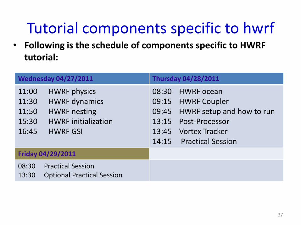
Tutorial components specific to hwrf• Following is the schedule of components specific to HWRF
tutorial:
Wednesday 04/27/2011 Thursday 04/28/2011
11:00 HWRF physics11:30 HWRF dynamics11:50 HWRF nesting15:30 HWRF initialization16:45 HWRF GSI
08:30 HWRF ocean09:15 HWRF Coupler09:45 HWRF setup and how to run13:15 Post-Processor13:45 Vortex Tracker14:15 Practical Session
Friday 04/29/2011
08:30 Practical Session13:30 Optional Practical Session
37