Advanced 35 W Free-Piston Stirling Engine for Space Power ...
DOE/NASA/I 005-1 2 NASA TM-88886
I i
i
Overview of Free-Piston Stirling Engine Techology for Space Power Application
(NBS A-TY-88P 8 6 ) OV ER VIEW OP FR EE-PIS TCN N85- 12327 S T I R L I N G ENGINE TSCBNOLGGY F O R S P b C E € C U E R APPLICATION Final Peport :lJASa) 2 3 p A v a i l : W I S HC AC:3 /#? g P l LSCL 103 V n c l a s
r , j / o5 r' lr tFL+?: - .I
Jack G. Slaby National Aeronautics and Space Administration Lewis Research Center
.. . . . . . , . . : , , I . . . . . . . .. . .
Work performed for U.S. DEPARTMENT OF ENERGY Conservation and Renewable Energy Division of Building and Community Systems
' - * 8 a > , * - \
Prepared for
cosponsored by ASME, JSME, and JSES Honolulu, Hawaii, March 22-27, 1987
b Solar Energy Conference f

Overview of Free-Piston Stirling Engine Technology for Space Power Application
I
Jack G. Slaby National Aeronautics and Space Administration Lewis Research Center Cleveland, Ohio 441 35
Work performed for U.S. DEPARTMENT OF ENERGY Conservation and Renewable Energy Division of Building and Community Systems Washington, D.C. 20545 Under Interagency Agreement DE-A105-820R1005
DOEINASAII 005-1 2 NASA TM-88886
Prepared for Solare Energy Conference cosponsored by ASME, JSME, and JSES Honolulu, Hawaii, March 22-27, 1987

Overview o f Free-Pis ton S t i r l i n g Engine Technology For Space Power A p p l i c a t i o n
v) cn N c) I
W
b y
Jack G. S laby
N a t i o n a l Aeronautics and Space A d m i n i s t r a t i o n Lewis Research Center
Cleveland, Ohio 44135
ABSTRACT
An overv iew i s presented o f t h e N a t i o n a l Aeronautics and Space A d m i n i s t r a t i o n (NASA) Lewis Research Center (LeRC) f r e e - p i s t o n S t i r l i n g engine a c t i v i t i e s d i r e c t e d toward space-power a p p l i c a t i o n . Free-p is ton S t i r l i n g technology i s a p p l i c a b l e f o r b o t h s o l a r and nuc lear powered systems. As such, t h e NASA Lewis Research Cen- t e r serves as t h e p r o j e c t o f f i c e t o manage t h e newly i n i t i a t e d SP-100 Advanced Technology program. T h i s program p r o v i d e s t h e technology push f o r p r o v i d i n g sig- n i f i c a n t component and subs,ystem o p t i o n s f o r increased e f f i c i e n c y , r e l i a b i l i t y and s u r v i v a b i l i t y , and power o u t p u t growth a t reduced s p e c i f i c mass.
development o f advanced power convers ion o f which t h e S t i r l i n g c y c l e i s a v i a b l e candidate. gram t h e s t a t u s o f t h e 25 kWe opposed-piston Space Power Demonstrator Engine (SPDE) i s presented. Inc luded i n t h e SPDE d i s c u s s i o n are i n i t i a l d i f f e r e n c e s between p r e d i c t e d and exper imental power o u t p u t s and power out - p u t in f luenced by v a r i a t i o n s i n regenera tors .
Technology work i s a l s o conducted on heat-exchanger concepts, b o t h design and f a b r i c a t i o n , t o min imize the number o f j o i n t s as w e l l as t o enhance t h e heat t rans- f e r i n t h e heater . Design parameters and conceptual design f e a t u r e s are a l s o presented f o r a 25 kWe, s ingle- c y l i n d e r f r e e - p i s t o n S t i r l i n g space-power conver te r . P r o j e c t i o n s a r e made f o r f u t u r e space-power requirements over t h e n e x t few decades along w i t h a recommendation t o cons ider t h e use o f dynamic power-conversion systems- e i t h e r s o l a r o r nuc lear . sented showing t h e mass b e n e f i t s t h a t a S t i r l i n g system has over a Bray ton system f o r t h e same peak temperature and o u t p u t power.
b i l i t y o f s c a l i n g a s i n g l e - c y l i n d e r f r e e - p i s t o n S t i r l i n g space-power module t o t h e 150 kWe power range i s pre- sented. The work d iscussed i n t h i s paper i s s y n e r g i s t i c w i t h t h e NASA Advanced So lar Dynamic Program where NASA Lewis i s conduct ing research on advanced concentrator, r e c e i v e r and thermal energy s to rage systems a t tempera- t u r e s around 1000 K f o r S t i r l i n g and Brayton c y c l e power convers ion systems.
One o f t h e major elements o f t h e program i s t h e
Under t h i s pro-
A c u r s o r y comparison i s pre-
A d e s c r i p t i o n o f a study t o i n v e s t i g a t e the feas i -
INTRODUCTION
Free-p is ton S t i r l i n g techno logy was s t a r t e d w i t h t h e work o f W i l l i a m Beale a t Ohio U n i v e r s i t y around 1962. T h i s e a r l y work r e s u l t e d i n smal l -sca le f r a c t i o n a l - horsepower enqines which demonstrated b a s i c engine o p e r a t i n g p r i n c i p l e s . The p o t e n t i a l advantages ( h e r - m e t i c a l l y sealed, h i g h e f f i c i e n c y , and s i m p l i c i t y ) of t h i s t y p e o f enqine became more w i d e l y recoqnized i n t h e e a r l y 1970's. T h i s r e c o g n i t i o n r e s u l t e d i n l a r g e r com- panies t a k i n g an i n t e r e s t i n i t s development f o r heat pumps and s o l a r a p p l i c a t i o n s .
took an i n t e r e s t i n heat pump development. One area o f s p e c i f i c i n t e r e s t t o t h e DOE i s t h e f r e e - p i s t o n S t i r l i n q engine-dr iven h e a t pump. C o i n c i d e n t a l l y , NASA Lewis was conduct ing research on f r e e - p i s t o n S t i r l i n q engines as one o f severa l candidates f o r p o t e n t i a l space-power systems. A l though b o t h a p p l i c a t i o n s , r e s i d e n t i a l h e a t pumps and space power, appear q u i t e d i f f e r e n t , t h e i r requi rements complement each o ther . i n c l u d e h i g h e f f i c i e n c y , t h e p o t e n t i a l f o r l o n g l i f e and h i g h r e l i a b i l i t y , low v i b r a t i o n , and hermet ic s e a l i n g . These common requi rements became the b a s i s f o r a coop- e r a t i ve in te ragency agreement ( IAA) between DOE/Oak Ridge N a t i o n a l Labora tory (ORNL) and NASA Lewis s igned September 1982. The research r e s u l t i n q f rom t h i s I A A covers gener ic f r e e - p i s t o n S t i r l i n g techno logy a p p l i - c a b l e t o b o t h space power and t e r r e s t r i a l heat pump a p p l i c a t i o n . T h i s gener ic technoloqy e f f o r t w i l l n o t be addressed f u r t h e r as p a r t o f t h i s paper due t o a l e n g t h r e s t r i c t i o n . Reference 1 covers some o f t h e q e n e r i c work. However, t h i s work i s very impor tan t t o b e t t e r understand t h e fundamentals o f f r e e - p i s t o n S t i r l i n q technology.
I n a d d i t i o n t o t h e DOE/ORNL - NASA Lewis p r o j e c t s , an in te ragency aqreement has been siqned between DOE/ Sandia N a t i o n a l Labora tory and NASA/Lewis t o u t i l i z e S t i r l i n g space technoloqy f o r s o l a r thermal t e r r e s t r i a l a p p l i c a t i o n f o r genera t ing s o l a r der ived e l e c t r i c a l
S h o r t l y t h e r e a f t e r , t h e Department o f Energy (DOE)
These requ i rements
power. And f i n a l l y , t h e SP-100 Space Reactor Power Program
was e s t a b l i s h e d by NASA, t h e Defense Advanced Research P r o j e c t s Agency, Department of Energy (DOE) and t h e A i r Force i n February 1983. For almost 3 years var ious
1

power convers ion concepts were inves t iga ted , u n t i l r e c e n t l y , when t h e thermoe lec t r i c concept was chosen f o r development and ground t e s t i n g t o be conducted u n t i l 1991. T h i s SP-100 program i s now i n t h e f i r s t year o f a 5-year phase I1 Ground Engineer ing System (GES) pro- gram. I n suppor t o f t h i s program, f r e e - p i s t o n S t i r l i n g system techno logy development i s c o n t i n u i n g under t h e newly i n i t i a t e d SP-100 Advanced Technology Program. NASA Lewis Research Center serves as t h e p r o j e c t o f f i c e f o r NASA's SP-100 Advanced Technology Program, t h e pur- pose o f which i s t o demonstrate t h e technology necessary t o proceed i n t o f i n a l development o f a space-qua l i f ied f r e e - p i s t o n S t i r l i n g engine t o meet f u t u r e m i s s i o n needs. work descr ibed i n t h i s r e p o r t i s e i t h e r conducted a t o r managed b y t h e NASA Lewis Research Center i n suppor t o f t h e NASA SP-100 Advanced Technology Program.
WHY FREE PISTON?
The
The f r e e - p i s t o n S t i r l i n g advanced technology
The S t i r l i n g f ree-p is ton system has many a t t r a c t i v e a t t r i b u t e s , severa l o f which a r e t a b u l a t e d i n F i g . 1. S p e c i f i c a l l y , t h e S t i r l i n g c y c l e i s t h e most e f f i c i e n t thermodynamic heat engine c y c l e t h a t e x i s t s . concepts considered f o r SP-100 s e l e c t i o n , t h e S t i r l i n g c y c l e has t h e h i g h e s t e f f i c i e n c y f o r t h e same g iven heat i n p u t and heat r e j e c t i o n temperatures. S t i r l i n g system employs the gas b e a r i n g - e i t h e r hydro- dynamic o f h y d r o s t a t i c - there i s t h e p o t e n t i a l f o r l o n g l i f e and h i g h r e l i a b i l i t y .
a l t e r n a t o r has o n l y two moving p a r t s p e r c y l i n d e r - t h a t i s t h e d i s p l a c e r and t h e power p i s t o n l a l t e r n a t o r p lunger . The r e s u l t i s a r e l a t i v e l y s imp le conf igura- t i o n . A s i n g l e - c y l i n d e r engine can be balanced e i t h e r a c t i v e l y o r p a s s i v e l y us inq a spring-mass combinat ion.
Free-p is ton S t i r l i n g engines c o n t a i n no s l i d i n g r o d s e a l s such as those present i n t h e k inemat ic concepts. The energy conserved b y not hav ing t o overcome t h e l o s s e s i n t h e f r i c t i o n a l rod sea ls i s n o t t o t a l l y f r e e . The f r e e - p i s t o n S t i r l i n g concept u t i l i z e s gas s p r i n g s wh ich have h y s t e r e s i s losses. A t t h e present t ime, i t i s n o t known whether t h e f ree-p is ton concept o r t h e k i n e m a t i c concept ' i s t h e most e f f i c i e n t , b u t i t i s f e l t t h a t t h e r e shou ld n o t be much d i f f e r e n c e between t h e e f f i c i e n c i e s o f t h e two concepts. The f a c t t h a t t h e r e i s no o i l i n s i d e t h e engine makes t h e f r e e - p i s t o n a s t r o n g cand ida te f o r l o n g l i f e . There i s no chance o f g e t t i n g o i l con taminat ion i n t o t h e regenera tor and degrad ing engine performance. An opposed-piston f r e e - p i s t o n S t i r l i n g engine w i t h a common expansion space, t h e o r e t i c a l l y has t h e p o t e n t i a l f o r g r a c e f u l degradat ion i n t h e event t h a t one engine has l a r g e r losses t h a n t h e o ther . Both p i s t o n s then produce equal power, b u t a t a reduced l e v e l .
i b l e i n t h a t n o t o n l y i s a l i n e a r a l t e r n a t o r poss ib le , b u t so a r e o t h e r concepts. These concepts i n c l u d e t h e h y d r a u l i c o u t p u t w i t h a hydrau l i c motorlpump and a con- v e n t i o n a l r o t a t i n g a l t e r n a t o r ; and a h y d r a u l i c d r i v e l g a s compressor o u t p u t which can p r o v i d e gas t u r b i n e power t o a convent iona l o r h i g h speed a l t e r n a t o r .
STIRLING/BRAYTON SYSTEM MASS COMPARISONS
O f t h e
Because t h e
A system composed o f a S t i r l i n g e n g i n e / l i n e a r
The power o u t p u t of the f r e e - p i s t o n i s very f l e x -
Reference 2 has assembled i n f o r m a t i o n f r o m var ious NASA Lewis conducted dynamic space power systems anal - yses. t h e d i f f e r e n t nuc lear and s o l a r dynamic power system techno log ies on t h e b a s i s o f system mass and drag area w i t h emphasis on t h e growth space s t a t i o n a p p l i c a t i o n . The comparisons presented here, based on these r e f e r - ences, show o n l y t h e mass v a r i a t i o n , and a r e considered
The purpose o f t h e Ref. 2 s t u d y was t o compare
p r e l i m i n a r y , i n t h a t r e s u l t s can be expected t o change as assumptions and analyses are r e f i n e d and as d i f f e r e n t t r a d e o f f s a r e examined. However, i t i s b e l i e v e d t h a t t h e r e l a t i v e comparisons a r e b a s i c a l l y v a l i d . It i s c l e a r t h a t o t h e r system c h a r a c t e r i s t i c s such as cos t , r e l i a b i l i t y , development s t a t u s and s a f e t y w i l l g r e a t l y impact a d d i t i o n a l comparisons. s tudy a 40 kWe s o l a r dynamic system module s i z e was assumed, w i t h f o u r modules produc inq 160 kWe. Each module i s a se l f -con ta ined power system c o n s i s t i n g of a s o l a r c o l l e c t o r , heat r e c e i v e r , power convers ion system ( i n c l u d i n g engine and energy s to raqe) , power system r a d i a t o r , and power c o n d i t i o n i n q system.
The n u c l e a r dynamic system c o n s i s t s o f a s i n g l e l i q u i d - m e t a l coo led r e a c t o r , a man-rated r a d i a t i o n s h i e l d , m u l t i p l e Brayton o r S t i r l i n g engines ( f o r redundancy), power system r a d i a t o r s , and power c o n d i t i o n i n g .
The o p e r a t i n g parameters f o r t h e s o l a r dynamic system a r e shown i n F ig . 2. These parameters a r e shown f o r b o t h s o l a r Brayton and s o l a r S t i r l i n g systems. For t h e Brayton system, t h e t u r b i n e i n l e t temperature i s 1083 K, w h i l e f o r t h e S t i r l i n g engine, t h e engine i n l e t temperature i s 1089 K. For t h e Brayton system, t h e compressor i n l e t temperature, compressor p ressure r a t i o , and recupera tor e f f e c t i v e n e s s were s e l e c t e d t o y i e l d a minimum system mass. The c y c l e temperature r a t i o f o r t h e S t i r l i n g engine was s e l e c t e d as a compromise b e t - ween system mass, c o l l e c t o r s ize , and r e q u i r e d r a d i a t o r heat t r a n s f e r area. 64 percent of Carnot, which a l s o inc ludes t h e a l t e r n a t o r e f f i c i e n c y , was assumed. T h i s represents a near-term s ta te -o f - the-ar t des ign f o r f r e e - p i s t o n S t i r l i n q space power systems. 40 kWe S t i r l i n q power module.
media i s e i t h e r L i F o r LiOH. c l o s e d Brayton c y c l e enqine i s more developed t h a n t h e f r e e - p i s t o n S t i r l i n q , b u t t h e f r e e - p i s t o n S t i r l i n g o f fe rs t h e p o t e n t i a l f o r h i g h e r convers ion e f f i c i e n c y w i t h lower r e q u i r e d c o l l e c t o r and r a d i a t o r area.
The nuc lear dynamic system parameters a re a l s o shown i n F i g . 2. a n a l y s i s were f o r a l i q u i d meta l coo led r e a c t o r w i t h t h e c o o l a n t e x i t i n g t h e r e a c t o r a t 1100 K. The mass and s i z e o f t h e r e a c t o r a r e based on models s u p p l i e d by t h e Los Alamos N a t i o n a l Labora tory (LANL). For t h e Brayton system t h e compressor i n l e t temperature and pressure r a t i o were s e l e c t e d as a t r a d e - o f f between minimum sys- tem mass and r a d i a t o r heat t r a n s f e r area. The recuper- a t o r e f f e c t i v e n e s s assumed was based on a separate ana lys is . The b a s i s f o r t h e S t i r l i n g system parameters a r e s t u d i e s conducted b y system c o n t r a c t o r s d u r i n q t h e Phase I p o r t i o n o f t h e SP-100 concept s e l e c t i o n . The n u c l e a r power system c o n s i s t s o f t h e nuc lear r e a c t o r enveloped b y a shaped 4 n, man-rated r a d i a t i o n s h i e l d . The n u c l e a r power system i s separated a d i s t a n c e f r o m t h e space s t a t i o n h a b i t a t b y a boom o r t e t h e r , w i t h e l e c t r i c i t y b e i n g t r a n s m i t t e d dowq t h e boom o r t e t h e r v i a a power cab le . The nuc lear r e a c t o r i s assumed t o be 30 m f rom t h e space s t a t i o n h a b i t a t .
a n u c l e a r Bray ton and a n u c l e a r S t i r l i n q system a t 150 kWe. systems. c e n t l i g h t e r than t h e n u c l e a r Brayton system. advantage i s p r i m a r i l y due t o i t s h i g h e r convers ion e f f i c i e n c y r e s u l t i n g i n lower s h i e l d mass and i n a sub- s t a n t i a l l y s m a l l e r r a d i a t o r r e s u l t i n g f r o m S t i r l i n g ' s h i g h e r e f f i c i e n c y and h i g h e r heat r e j e c t i o n temperature. The d i f f e r e n c e i n power l e v e l between t h e 150 kWe n u c l e a r and t h e 160 kWe s o l a r i s t h e r e s u l t o f u s i n g a v a i l a b l e data.
For t h e purpose of t h e
A S t i r l i n g enqine e f f i c i e n c y o f
The enqine s p e c i f i c mass used was f o r a
I n t h e s o l a r s t u d y considered, t h e heat s to rage Keep i n mind t h a t t h e
The n u c l e a r r e a c t o r models used i n t h i s
F i g u r e 3 q i v e s a comparison o f system we igh t between
C l e a r l y t h e man-rated s h i e l d dominates bo th The n u c l e a r S t i r l i n q system i s about 13 per-
T h i s mass
The 160 kWe s o l a r i s composed o f 4 t o
2

40 kWe modules. existing 150 kWe system.
Figure 4 compares the solar dynamic systems. the Stirling system is at least 25 percent lighter than the Brayton system. upon Stirling engine mass and efficiency assumptions used for SP-100 phase I calculations and includes mass estimates for the solar receiver and collector which were scaled from the Brayton system analysis. Thus, the absolute values should be considered tentative, pending more detailed analysis and modelling using a solar heat source. Brayton system is not expected to change.
and Stirling systems each using solar and nuclear energy sources. The solar power systems are assumed to scale linearly with power, while the nuclear power systems scale less than linearly.
In all cases the Stirling system, because of its high efficiency, is the lighter system.
FUTURE SPACE POWER PROJECTIOCS
Whereas the nuclear system was an
Here
The mass results shown are based
The relative Stirling advantage over the
Figure 5 shows total system mass for both Brayton
Over the next several decades, the amount of elec-
Most of these satellites are powered
tric power required in space is expected to grow immensely. Today's larger satellites require almost 10 kWe of power. by solar arrays with storage batteries. space platforms will continuously require hundreds of kilowatts; and some will periodically consume many meg- awatt-hours of energy. These space platforms will include manned space stations, communication stations, surveillance platforms, and defense weapons. These large power systems will be quite different from today's solar arrays.
trends as shown in Fig. 6. These broad trends are a direct result of uncertainties in future mission capa- bilities and needs. It is however, clear that future space power needs may be several orders of magnitude greater than anything that has been accomplished to date. The challenge for the space power planner is formidable - to select power technologies that can meet the projected trends and adapt to multiple users. One potential solution is the use of dynamic power conver- sion units - either solar or nuclear.
Figure 7 is an artist's conception of an SP-100 Stirling engine system. The concept uses a nuclear reactor and shield along witti both fixed and deployed radiator panels. Thermoelectric electromaqnetic pumps are employed to transport the hot liquid from the reac- tor to the Stirling engines.
SCALING STUDY
Tomorrow's
Projections of space power growth tend to show broad
The free-piston Stirling engine is an emerging can- didate for space-power missions using either nuclear or solar heat sources. designs, hardware fabrication, and testing below the 25 kWe power range. tion Future Space Power Projections it is readily apparent that single-cylinder engines with power outputs above 100 kWe per cylinder are very desirable. There- fore, it is important to determine whether it is feas- ible to design a single-cylinder FPSE/LA system in the 100 to 150 kWe range.
awarding a small competitive contractual effort to investigate whether single-cylinder FPSE/LA systems can be designed in the 100 to 150 kWe power range. As part Of this study recommendations will also be made for configurations other than linear alternators. Are there other configurations that may offer advantages over the
Recent work has keyed on FPSE
However, as discussed in the sec-
As a consequence, NASA Lewis is in the process of
linear alternator configuration? scope of the work being considered under this study. The study will cover the power ranqe from 25 through 150 kWe per cylinder. determine the maximum power per cylinder if indeed it becomes apparent that power levels greater than 150 kWe per cylinder are feasible. The study will key on engine temperature ratios in the range of 1.7 to 3. It is in this range that the contractor will be asked to estab- lish parametric relationships between percent Carnot cycle efficiency and specific mass, output power, and temperature ratio of the power conversion unit (i .e., Stirling engine plus linear alternator). study will key on a temperature level of about 1050 K so that superalloys can be used. The design life shall be about 60 000 hr with helium as the working fluid and a specific mass target range of 5 to 8 kg/kWe.
SPACE POWER DEMONSTRATOR ENGINE (SPDE)
Figure 8 outlines the
An option to the study is to
This initial
NASA Lewis, in coordination with the overall SP-100 development proqram, initiated an SP-100 Advanced Technoloqv Program. The objectives of the Advanced Technology program are to auqment the qround enqineerinq system (GES) enqineerinq development and qround testinq of major subsystems and to provide siqnificant component and subsystem options for increased efficiency, relia- bility, survivability, and qrowth, at reduced weight and high reliability. Thus, enhancinq the chances of suc- cess for the overall SP-100 power system development.
These goals will be obtained through the key ele- ments of the broadly based proqram which include: sys- tems analysis to quide the overall effort and advanced technology development in the areas of Enerqy Conver- sion, Thermal Management, Power Conditioning and Control, Space Power Materials and Structures, and Spacecraft Environmental Effects. Building upon the technoloqy advancements accomplished in Phase I of the SP-100 program, the advanced Stirling technology con- version project is one important element of the proqram. The key Stirling technoloqy areas needed for this broadly based program are listed in Fis. 9.
In concert with the Advanced Technology Program a demonstrator enqine was built and is currently under test. Enqine (SPDE). Mechanical Technoloqy, Inc. (MTI) of Latham, NY. The enqine is currently under test at this facility. The nominal design was 25 kWe from the two opposed-piston Stirlinq enqine - linear alternator system. A photo- qraph of the engine is shown in Fiq. 10. The enqine is about 1-1/4 m in length and about 1/3 m in diameter. It is suspended from the ceilinq by four vertical straps. This flexible suspension was the test config- uration and no discernible vibration was observed during operation. Accelerometers mounted on the engine housing indicated maximum amplitudes (peak-to-peak) of less than 0.01 mm which corresponds to a "9" of less than 0.2. A qeneral description of the enqine is qiven in Refs. 3 and 4. Fiqure 11 is a cross section of half of the engine taken throuqh a line of symmetry. module shown was desiqned to produce 12.5 kWe - half the full engine power.
Because of the tight schedule to design, fabricate, and test the engine, the maximum engine temperature for initial testing was limited to 650 K. The cost of a liquid metal facility (necessary for hiqher temperature operation) was also a factor in selecting 650 K as the heater temperature. The cold or cooler temperature was maintained at 325 K in order to operate the engine at a temperature ratio of 2. The temperature ratio of 2 was chosen for a minimum weight system (including reactor and radiator).
The engine is called the Space Power Demonstrator The SPDE was designed and fabricated by
The
The SPDE is a development engine and, as such, is not a final space configuration. However with straight- forward material substitutions and replacing bolts and flanges with welds, the SPDE specific mass at design power is reduced to 7.2 kg/kWe from the laboratory specific mass of 12.7 kg/kWe.
The top curve of Fig. 12 shows predicted piston PV power at the design pressure - 150 bar - and design temperature ratio of 2.0. The piston PV power is pre- sented instead of alternator output power because the alternator is currently not performing as expected. A detailed investigation is planned in regard to improving alternator performance. The bottom curve of Fig. 12 shows the PV power obtained with a regenerator that became damaged during the first 20 hr of 105 Hz opera- tion. The power was about half the predicted power for a given piston amplitude (piston stroke is twice the piston amplitude); yet the engine ran well. This power shortfall was unexpected beciiuse at the half design pressure of 75 bar the experimental power was about 90 percent of the predicted power (6.0 kW experimental, 6.7 kW predicted with an alternator efficiency of about 93 percent). Keep in mind that the engine frequency also changes with engine pressure. At 75 bar the engine frequency-is 74 hz and at 150 bar the frequency is 105 hz. A concentrated effort was conducted by both MTI and NASA to resolve the power shortfall problem. On balance, the mechanical operation of the engine has been flawless. Both power pistons (alternator plungers) and one displacer have been completely trouble-free. One displacer drive was troublesome until a positive cyl- inder alignment was incorporated into the design. In order to understand why there was a power shortfall additional instrumentation was.added to the engine as well as a complete recalibration of all flow meters, resistance temperature devices, and pressure sensing devices. Thermocouples were located at the interface of each heat exchanger (i .e., heater - regenerator, regenerator-cooler, etc.).
A series of diagnostic tests were conducted in order to isolate potential power shortfalls. The tests con- sisted of cold and at temperature motoring tests with the displacer (one of the two movinq parts per engine) locked in place. A motor-generator set supplied power to motor the alternator of the SPDE. these tests was to determine whether gas leakage and/or hysteresis are a cause of the power shortfall. tional motoring tests were conducted with both displacer and piston unlocked at a temperature ratio of 1. This test verified that leakage and/or hysteresis were not contributing to the power shortfall. The SPDE engine is at the forefront of Stirling technology and operates at 105 Hz, 1.75 times greater than previously designed Stirling engines (the equivalent to an automobile engine at 6300 rpm). As such, the higher frequency generates large dynamic oscillating forces on the regenerator which have resulted in regenerator fretting and damage. Previous free-piston Stirling regenerators - due to low frequency operation and to the low pressure ratio of free-piston engines - were not sintered or canned and maintained their integrity over long periods of operati on.
ran over 5500 hr without any regenerator problems. Nevertheless, Fig. 13 shows a comparison between the uncanned, unsintered screen regenerators before testing and after only about 20 hr of 105 Hz operation. Sin- tered and canned regenerators are on order for future testing . a sintered - though not optimized - regenerator of a smaller diameter wire and higher porosity. the replacement regenerator is shown in Fig. 14.
The purpose of
Addi-
As an example, the nominal 3 kW MTI Endurance Engine
The damaged screen regenerators were replaced with
A photo Of
Although the regenerator was not optimum the performance improvement was dramatic. This can be seen by the mid- dle curve in Fig. 12. power to the linear alternators at only 85 to 90 percent of full pistonlalternator plunger stroke. Engine oper- ation at this power level was made possible by the mod- ification of an element of the load circuit which had previously prevented achievement of power levels greater than 14 kW. This modification was in addition to the regenerator replacement. pistonlalternator plunger could not be reached at this time because of a proqressive loss of pas bearing pres- sure with increase in alternator power. The loss of bearing pressure appears to be caused by a widening o f the clearance gap between the piston and its cylinder. It is believed that heat rejected by the alternator causes expansion of the cylinder relative to the piston. Alternator efficiency at this power level is approxi- mately 70 percent - considerably lower than the alter- nator design efficiency of 93 percent that was measured at lower power levels. The specific source of alterna- tor power loss is currently being identified by work being done both by the Contractor (MTI) and by NASA Lewis personnel. The final testing is far from complete and early indications are that further power improvement is expected when the sintered screen regenerators are installed.
25 kWe SINGLE CYLINDER CONCEPT
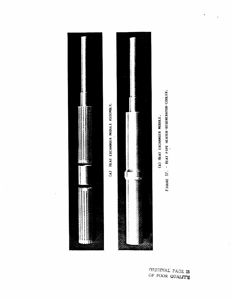
Under SP-100 funding, Sunpower, Inc., of Athens, Ohio generated parametric relationships for free-piston Stirling engine 1 inear alternator (FPSE/LA) systems such that for specified heater-to-cooler temperature ratios, equations were established to represent the interde- pendency between the FPSE/LA specific mass and percent of Carnot cycle efficiency. Sunpower then used these relationships to generate a conceptual design for a 25 kWe single-cylinder space power module incorporating refractory metal heat exchanger modules. The refractory heater module engine design parameters are listed in Fig. 15. material was chosen as a refractory metal alloy niobium and zirconium (Nb-1Zr). The lifetime requirement was 70,000 hr and the heater temperature was 1080 K. Not listed under desiqn parameters is the fact that hydro- dynamic qas bearinqs were used on both reciprocatinq components, the displacer and the power piston (linear alternator plunqer). The basic power module is a simple sinqle-piston displacer desiqn using an adaptive dynamic balance unit to minimize forces transmitted to the sup- port structure. The dynamic balance unit, the heat-pipe heat exchanqer assemblies, and the use of hydrodynamic gas bearings represent the only departure from conven- tional FPSE technology. A cross section of this concept is shown in Fig. 16 with a superalloy hot end. desiqn incorporates approximately 40 heat exchanger assemblies, one of which is schematically shown in Fig. 17 (assembled and unassembled). The module con- sists of a heater, regenerator, and cooler encased in a single tubular structure. This design contrasts with the conventional multitube (1600 tube heater and 1900 tube cooler) heat exchanqers used in the SPOE. It significantly reduces the number of fabrication joints and also provides a better match of heat transfer bet- ween the liquid-metal side and the helium workinq fluid side. Sunpower and MTI are usinq used this sinqle- cylinder concept as the basis for a preliminary design. This preliminary design will have a superalloy hot end. This work is currently underway. The preliminary design will be modified into an experimental version; and will
The engine delivered 20.5 kW of
Full design stroke of the
It is of interest,to note that the heater
This
4

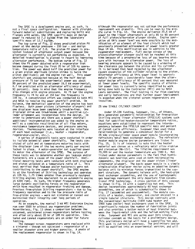
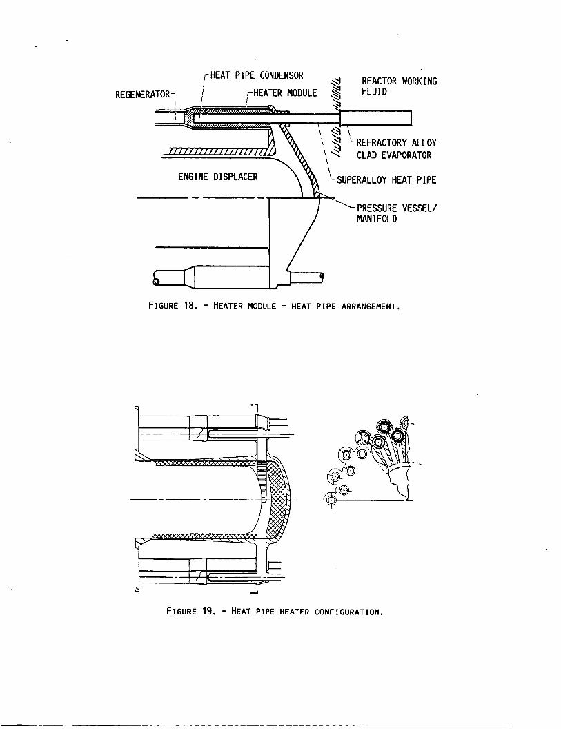
be designed for research instrumentation, ease of com- ponent modification, and ease of assembly and disassem- bly. By using super alloys for the heat exchangers it is easier, less expensive and faster to test and evalu- ate than a refractory metal engine. This engine, when built, will be tested at NASA Lewis in Cleveland, Ohio. The design conditions are listed in Fig. 15. In any event, heat pipes will be used to supply heat to the engine. At present interest is focused on the use of heat pipes inserted into modified heater modules as shown schematically in Fig. 18. A major advantage of this concept is the fact that the liquid metal is con- tained within the heat pipe and is not in contact with highly stressed engine components. Another feature of this design is the portion of the heat pipe in contact with the reactor working fluid can be clad with the same material that the reactor loop is fabricated from. Thus the potential for loop contamination by engine materials is avoided. concentric rings symnetrical around the displacer. This is shown in Fig. 19.
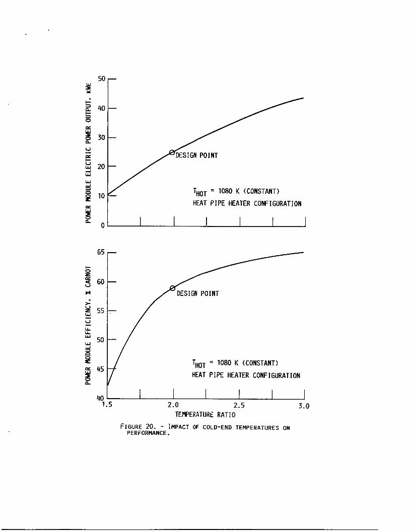
Carnot cycle efficiency as the cold end (cooler) tem- perature is varied for a constant hot temperature o f 1080 K. ered from 540 to 360 K the output power increases from 25 to 44 kw and the percent Carnot cycle efficiency increases from 59 to 65 percent. engine is optimized at .a temperature ratio of 2. engine were reoptimized at a temperature ratio of 3 (360 K cooler temperature) the power and efficiency improvement would be even-better. For this reason it is highly desirable to operate the Stirling engine at the highest possible temperature ratio. systems are optimized for minimum systems weight, nuclear Stirling systems tend to optimize around tem- perature ratios of 2.0; and solar Stirling systems optimize around temperature ratios of around 2.5. numbers vary slightly with varying missions. Even though this engine will not be tested for at least a couple of years, some of the heat exchanqer assemblies as previously shown in Fig. 17 will be fabricated and tested separately. Three heat exchanger assemblies will be fabricated of materials proposed for this superalloy Stirling Space Engine. The assemblies will be flow- tested under both steady state and oscillatinq flow to verify design parameters. The flow rig is beinq built by Sunpower under a small business innovative research (SBIR) contract.
incorporates many technology advances over the SPDE design. Fig. 21 lists some o f these advances. Even though the temperature ratio of 2 is used for each design, the maximum temperature for the SSE design is raised more than 400 to 1080 K. This design is opti- mized for minimum specific mass (30 percent reduction over SPDE) and uses a heat pipe heater. Incorporated in the heat pipe heater design is a factor of 40 reduc- tion in number of heater tubes. SPDE has 1600 tubes in the heater whereas the SSE design uses 40 heat exchanger modules - adding greatly to the simplicity and relia- bility of operation. The SSE design uses self energized hydrodynamic spin 1 ubricated gas bearings whereas SPDE USeS externally pumped hydrostatic gas bearings.
The forty heat pipes are arranged in two
Figure 20 shows the impact on power and percent of
If the design point cooler temperature is low-
Keep in mind that the If the
However, when
These
The 25 kWe super alloy Stirling space engine design
A
separate radiator will be used to cool the magnets in the SSE thereby providing flexibility in choosing the cooler temperatures - which is important in determining the system radiator mass. liquid metal - probably sodium in the heat pipe design - which ensures a uniform heater temperature. finally the power per cylinder is increased by a factor of 2 over the SPDE design to 25 kW per cylinder. This single cylinder SSE engine employs an active dynamic balance to reduce vibration to acceptable values - less than 3 mils engine casing amplitude.
CONCLUDING REMARKS
The SSE design also uses
And
The space power demonstrator enqine (SPDE) has suc- cessfully operated for over 300 hr and has delivered 2 0 kW of PV power to the alternator plunger. The SPDE has demonstrated that a dynamic power conversion system can be, with proper design, balanced; and the engine per- formed well with externally pumped hydrostatic gas bearings. Testing of the engine will continue its steady development and will provide a test bed to eval- uate new and unproven componentsltechnologies.
A 25 kWe sinqle-cylinder Stirling space engine design is underway incorporating many advanced design features required for a prototypic flight engine. This engine uses super alloy materials and wherever possible uses concepts and components applicable for refractory metal (1350 K) application. This design features mod- ular heat exchangers with sodium heat pipes, thereby, dramatically reducing the number of joints and enhancing the heat transfer capability.
In conclusion, we feel that the free-piston Stirling engines are just startinq to achieve the attention and creditability that they deserve for space-power appli- cation. Free-piston Stirling systems can easily be used with both solar and nuclear powered svstems and offer the potential for high efficiency, long life and hiqh reliability.
REFERENCES
1.
2.
3.
4.
Slaby, J.G., "Overview of Free-piston Stirling Technoloqy at the NASA Lewis Research Center," NASA
Nainiger, J.J. and McKissock D.B., "Mass, Area, and Propellant Requirement Comparisons of Several Potential Growth Space Station Power Systems," Preliminary Information Report No. 71, Space Station System Directorate, NASA Lewis Research Center, Cleveland, OH, Oct. 1984.
Dochat G.R., "Free-Piston Stirlinq Enqines for SDace
TM-87156, 1985.
Power," Proceedinqs of the TwentyLSecond Automotive Technology Development Contractorls Coordination Meeting, Society of Automotive Enqineers, Warrendale, PA, 1984 pp. 209-213.
Slaby, J.G. , "Overview of Free-Piston Stirling SP-100 Activities at the NASA Lewis Research Center," NASA TM-87224, 1986.
5

0 HIGH EFFICIENCY (RELATIVE TO OTHER SYSTEMS)
0 POTENTIAL FOR LONG LIFE AND HIGH RELIABILITY
0 NON-CONTACTING GAS BEARINGS
0 TWO MOVING PARTS
0 DYNAMICALLY BALANCED
0 NO ROD SEALS
0 NO OIL INSIDE ENGINE
0 POTENTIAL FOR GRACEFUL DEGRADATION
0 POWER OUTPUT FLEXIBILITY
FIGURE 1.- WHY FREE-PISTON STIRLING?
COMP. PRESSURE 1.8
RECUP. EFFECTIVENESS 0.860
RAT IO
BRAYTON
ENGINE SPECIFIC 6.0 KG/KW MASS
~~ ~~ ~~ ~ -
TURBINE INLET 0183 OK
COHP. INLET 321 OK
C W . PRESSURE RATIO 1.7
RECUP. EFFECTIVENESS 0.97
TEMPERATURE
TEMPERATURE
STIRLING ~~ ~~~ ~ ~ ~
ENGINE INLET 1089 OK
TEMPERATURE
CYCLE TEMPERATURE 2.5 RATIO
ENGINE EFFICIENCY 64% OF (ALTERNATOR CARNOT
ENGINE SPECIFIC 7.0 KG/KW
OUT./HEAT I N )
MASS
( A ) SOLAR DYNAMIC SYSTEMS PARAMETERS.
ST I RL I NG I BRAYTON ~~~ ~
REACTOR OUTLET 1100 OK
TURBINE INLET 1091 OK
COMP. INLET 436 OK
TEMPERATURE
TEMPERATURE
TEMPERATURE
REACTOR OUTLET 1100 OK
CYCLE TEMPERATURE 2.0
ENGINE EFFICIENCY 64% OF (ALTERNATOR OUT./ CARNOT
TEMPERATURE
TEMPERATURE
HEAT I N )
(B) NUCLEAR DYNAMIC SYSTEMS PARAMETERS.
FIGURE 2.- DYNAMIC SYSTEMS PARAMETERS.

25
20
2 15
v, 3 10
5
MAN-RATED SHIELD
STRUCTURE’
POWER CONDITION I NG
TOTAL RADIATOR
ENG I NE
REACTOR
BRAYTON ST I RL I NG MASS, KG
FIGURE 3. - NUCLEAR DYNAMIC SYSTEM MASS. NEW POWER OUT- PUT = 150 KWE; REACTOR TEMPERATURE = 1100 K . DOSE RATES: AT HABITAT = 4 MREM/HR (30 M I : I N OPPOSITE DIRECTION FROM HABITAT = 200 MREM/HR (30 MI.
12 000
4 000
2 000
V; 6 0 0 0
(I Y
3
BRAYTON STIRLING
MASS. KG
STRUCTURES
RADIATORS
PCS TOTALS
HEAT RECEIVERS
MIRRORS
FIGURE 4. - SOLAR DYNAMIC SYSTEMS MASS. NET POWER OUT- EACH BAR REPRESENTS 4 - 40 KWE POWER PUT = 160 KWE.
SYSTEMS.

50 000
40 000
~3 Y 30 0001
v,
3 20 000
10 000
NUCl
NUCLEAR ST I RL I NG-’
‘-SOLAR STIRLING
0 50 100 150 200 250 300 350 NET ELECTRICAL OUTPUT, KWE
FIGURE 5. - TOTAL SYSTEM MASS FOR POTENTIAL SPACE STATION POWER SYSTEMS.
g E 4 10
1 CURRENT FUTURE SPACECRAFT
#C--
, / - lo2 t
I 1980 2000
CALENDAR YEAR
F I G U R E 6. - PLANNED SPACE POWER PROGRAMS ADDRESS SPACE- CRAFT GROWTH.

OMGDVAL, PAGE IS OF POOR QUALITY
C-85-8712
FIGURE 7. - ARTIST'S CONCEPTION OF SP-100 STIRLING SYSTEM.
0 DETERMINE DESIGN FEASIBILITY OF SINGLE-CYLINDER FPSE-LA IN THE 150 kWe RANGE
ESTABLISH PARAMETRIC RELATIONSHIPS PERCENT CARNOT CYCLE EFFICIENCY VERSUS SPECIFIC MASS AT TEMPERATURE RATIO AND POWER RANGE
0 ASSESS PROMISING ALTERNATIVE STIRLING CONFIGURATIONS
AWARD OPTIONS RE PEAT STU D YTO R ALTER NATE CON FI GU RATION CONDUCT DESIGN OF HIGH POWER SYSTEM DETERMINE M A X I M U M POWER; BEYOND 150 kWe
F igu re 8. - Space power FPSE sca l i ng study.

SUPPORTS KEY TECHNOLOGY AREAS NEEDED FOR :
0 GAS BEARINGS
0 L I NEAR ALTERNATORS
0 ALTERNATIVE POWER EXTRACTION
0 CODE VALIDATION AND ANALYSIS
0 OSCILLATING FLOW
0 PERFORMANCE PREDICTIONS
0 SCALING
0 HEAT EXCHANGERS
0 MATERIALS
0 POWER CONDITIONING INTERFACE
0 LONG L I F E VALIDATION
FIGURE 9, - LEW I s ADVANCED TECHNOLOGY PROGRAM.
C-85-7371
FIGURE 10. - 25 KWE SPACE POWER DEMONSTRATOR ENGINE (SPDE) AT
MECHANICAL TECHNOLOGY INC.

rDlSPLACER DOME SnvlMETRY 1 I
I PLWGERd ;:::-' ''-PISTON GAS SPRING
FIGURE 11. - 25 KWE SPDE.
'"E 5 25
I-
10
/ PREDICTED 0
0 0
// 0
/ 0 TH/Tc = 2.0 0
f = HOD IF I ED LOAD 7-11-86 TEST
DAMAGED J&W# REGFENERATOR
/@yC 11-22-85
0 5 6 7 8 9 10 11 12 PISTON AMPLITUDE. MM
FIGURE 12. - SPM Pv POWER AT 150 BAR.

BEFORE 105 HZ OPERATIOfi
AFTER 20 HR OF 105 Hz OPERATION
FIGURE 13. - COMPARISON OF SCREEN REGENERATORS.

ORIGINAL PAGE XS OF POOR QUALITY
FIGURE 14. - REGENERATOR COMPOSED OF ONE MIL-DIAMETER SINTERED W I R E .

REFRACTORY VERSUS SUPERALLOY
REFRACTORY SUPERALLOY
SPECIFIC MASS. KG/KW 5.8
ALTERNATOR POWER 25 ' OUTPUT, K W
5.5
25
ENGINE SYSTEM EFFICIENCY 28.5% 29.5% ( INCLUDES ALTERNATOR EFF . I
PERCENT CARNOT EFFICIENCY 57% (TR = 2.0)
59%
HEAT TRANSPORT SYSTEMS: HOT END PUMPED LOOP HEAT PIPE
0 COLD END PUMPED LOOP PUMPED LOOP
HEATER TEMPERATURES : MAX I MUM 1130 OK 1080 OK AVERAGE 1080 OK 1080 OK
AVERAGE COOLER TEMPERATURES
540 OK 540 OK
FIGURE 15.- 25 KWE SINGLE CYLINDEk SPACE STIRLING ENGINE REFERENCE DESIGNS.

REGENERATOR -I
LREFRACTORY ALLOY 7/// / / / / / / / / / / / / ' \ CLAD EVAPORATOR
F ENGINE DISPLACER 1 ~ J P E R A L L O Y HEAT PIPE
\
'- PRESSURE MAN I FOLD
-
FIGURE 18. - HEATER MODULE - HEAT P I P E ARRANGEMENT,
VESSEL/
.
FIGURE 19. - HEAT P I P E HEATER CONFIGURATION.
i m A r w VJ VJ < W d
0 x Q: W W z U I U X W
I- U w I
n U
a n
v
50 t . !-
c 2 40 s p:
30
-
THOT = 1080 K (CONSTANT)
HEAT PIPE HEATER CONFIGURATION
I
THOT = 1080 K (CONSTANT)
HEAT P I PE HEATER CONF I GURAT I ON
40 1.5 2.0 2.5 3.0
TEMPERATURE RATIO
FIGURE 20. - IMPACT OF COLD-END TEMPERATURES ON PERFORMANCE.

0 HEAT P IPE HEATER
0 DESIGN OPTIMIZATION FOR SPACE APPLICATION
0 SIMPLIFIED MODULAR HEAT EXCHANGERS
0 HYDRODYNAMIC SPIN LUBRICATED GAS BEARINGS
0 400 OK INCREASE I N HEATER TEMPERATURE; TEMPERATURE
0 SEPARATE RADIATOR TO COOL ALTERNATOR MAGNETS
POWER PER CYLINDER UP FACTOR OF 2
0 SINGLE CYLINDER ACTIVE DYNAMIC BALANCE
0 USE OF L I Q U I D METAL
0 REDUCED SPECIFIC MASS Z 30%
RATIO = 2.0; 1080 OK
FIGURE 21. - 25 KW SUPER ALLOY STIRLING SPACE ENGINE (SSE) TECHNOLOGY ADVANCES OVER SPDE.

1. Report No.
NASA TM-88886
Overview o f Free-Pis ton S t i r l i n g Engine Technology f o r Space Power A p p l i c a t i o n
- 2. Government Accession No.
7. Author(s)
17. Key Words (Suggested by Author(s))
F ree -p i s ton ; S t i r l i n g engine; Space power
Jack G. Slaby
18. Distribution Statement
U n c l a s s i f i e d - u n l i m i t e d STAR Category 85 DOE Category UC-96
9. Performing Organization Name and Address
N a t i o n a l Aeronaut ics and Space A d m i n i s t r a t i o n Lewls Research Center Cleveland, Ohio 44135
12. Sponsoring Agency Name and Address
U.S. Department o f Energy D i v i s i o n o f B u i l d i n g and Community Systems Washington, D . C . 20545
IS. Supplementary Notes
19. Security Classif. (of this report) 20. Security Classif. (of this page) 21. No. of pages
Unc l a s s i f i ed U n c l a s s i f i e d
3. Recipient's Catalog No
22. Price'
i 5 Report Date
i 6 Pertorming Organization Code
1 I
506-41 3A
I 8. Performing Organization Report No.
E--3295 I 10 Work Unit N o -1 -- -I
i 1 1 Contract or Grant No
I 13. Type of Report and Period Covered I I
Technica l Memorandum I
14. Sponsoring Agency C6XiReport No. ,
I
UOE/NASA/1005-12 I
F i n a l Report . Prepared under In te ragency Agreement DE-AI05-820R1005. Prepared f o r So la r Energy Conference cosponsored by ASME, JSME, and JSES, Honolu lu , Hawal i , March 22-27, 1987.
I
I 6 A b s t r a c t I
An overview i s presented o f the National Aeronautics and Space Actninistration (NASA) Lewis Research Center (LeRC) free iston S t i r l i n .engine ac t i v i t i es directed toward space-power application.
NASA Lewis Research Center serves as the project o f f i ce t o manage the newly i n i t i a ted SP-100 Advanced Technology program. subsystem options for increased effici-ency, re1 iabi 1 i t and survivabi 1 i t y , and power output grouth a t reduced specific mass. One o f the major elements o f tL program i s the development of advanced power conversion o f which the S t i r l i n g c c l e i s a viable-candidate. Under th i s program the status of the 25 kne opposed-piston Space Power 8emonstrator Engine (SPDE) i s presented. Included i n the SPDE dis- cussion are i n i t i a l differences between predicted and experimental power outputs and power output influenced by variations i n regenerators. Technology work i s also conducted on heat-exchanger con- cepts, both desi n and fabrication, t o minimize the nmber o f - j o i n t s as w e l l as t o enhance the heat transfer i n the #eater. Design parmeters and conceptual design features are also presented fo r a 25 kwe, single-cy1 inder free-piston S t i r l i n g space-power converter. Projections are made fo r future space-power requirements over the next fw decades along wi th a recomnendation t o consider the use o f d nmic power-conversion s stems-either solar o r nuclear. d e mass benefits that a S f i r l i n g system has over a Brayto?sG::zrfoF?e same pea! tenperature an% output power. free-piston S t i r l i n g space-power module t o the 150 kWe power range i s presented. The work discussed i n t h i s paper i s synergistic with the NASA Advanced Solar Dynamic Program where NASA Lewis i s con- ducting research on advanced concentrator, receiver and thermal energy storage systems a t temperatures around lo00 K fo r S t i r l i ng and Brayton cycle power conversion systms.
Free- piston S t i r l i n g te3nology i s app 9 icable fo r both solar and nuclear powered systems. As such, the '
This program provides the technology push fo r providing s ign i f icant carponent and
arison i s resented showin
A description o f a study t o investigate the f e a s i b i l i t y o f scaling a single-cylinder
I I I
'For sale by the National Technical Information Service, Springfield. Virginia 221 61