Overview of Additive Manufacturing Initiatives at NASA Marshall … · The First Step: The 3D...
36
1 Overview of Additive Manufacturing Initiatives at NASA Marshall Space Flight Center R.G. Clinton Jr., PhD Associate Director Science and Technology Office NASA Marshall Space Flight Center Airbus February 23, 2018 Taufkirchen, Germany https://ntrs.nasa.gov/search.jsp?R=20180001514 2019-03-01T16:24:50+00:00Z
Transcript of Overview of Additive Manufacturing Initiatives at NASA Marshall … · The First Step: The 3D...

1
Overview of Additive Manufacturing
Initiatives at NASA Marshall Space Flight
Center
R.G. Clinton Jr., PhD
Associate Director
Science and Technology Office
NASA Marshall Space Flight Center
Airbus
February 23, 2018
Taufkirchen, Germany
https://ntrs.nasa.gov/search.jsp?R=20180001514 2019-03-01T16:24:50+00:00Z

Contributors
2
• Niki Werkheiser: NASA MSFC In Space Manufacturing, Program Manager
• Dr. Tracie Prater: NASA MSFC In Space Manufacturing, Materials Characterization Lead
• Dr. Frank Ledbetter: NASA MSFC In Space Manufacturing, Subject Matter Expert
• Kristin Morgan: NASA MSFC Additive Manufacturing Lead
• John Fikes: NASA MSFC Additive Construction Project Manager; Additive Combustion Chamber Project Manager
• Andrew Owens: NASA Tech Fellow, MIT PhD Candidate
• Mike Snyder: Made In Space, Chief Designer
• Omar Mireles: NASA MSFC Engine Systems Design/Additive Manufacturing Designer
• Daniel Cavender: NASA MSFC Liquid Propulsion Systems Design; Small Thrusters
• Paul Gradl: NASA MSFC Liquid Engine Component Development and Technology, Lead, Nozzles
• Andy Hardin: NASA MSFC SLS Liquid Engines Office
• Dr. Doug Wells: NASA MSFC Lead, Additively Manufactured Space Flight Hardware Standard and Specification
• Brad Bullard: NASA MSFC Lead, Additive Injectors
• Sandy Elam Greene: NASA MSFC Lead, Additive Injectors
• Chris Protz, NASA MSFC Lead, Additive Combustion Chamber
• Jim Richard: NASA MSFC Lead, Additively Manufactured Valves
• Dave Eddleman: NASA MSFC Lead, Additively Manufactured Valves
• Travis Davis: NASA MSFC Lead, Additively Manufactured Valves
• Derek O’Neal: NASA MSFC Lead, Liquid Oxygen Pump
• Marty Calvert: NASA MSFC Lead, Turbopump

Agenda
NASA’s In Space Manufacturing Initiative (ISM)
• The Case for ISM: WHY
• ISM Path to Exploration
o Results from 3D Printing in ZeroG Technology
Demonstration Mission
o ISM Challenges
• In Space Robotic Manufacturing and Assembly (IRMA)
• Additive Construction
Additively Manufacturing (AM) Development For Liquid Rocket
Engine Space Flight Hardware
MSFC Standard and Specification For Additively Manufactured
Space Flight Hardware
Summary
3

The Case for ISM: WHY
Current maintenance logistics strategy will not be effective for deep space exploration missions
Benefits from Incorporation of ISMISM offers the potential to:
• Significantly reduce maintenance logistics mass requirements
• Enable the use of recycled materials and in-situ resources for more dramatic reductions in mass requirements
• Enable flexibility, giving systems a broad capability to adapt to unanticipated circumstances
• Mitigate risks that are not covered by current approaches to maintainability
4

AES Mid-year Review March 2017
In-Space Manufacturing (ISM) Path to Exploration
EARTH RELIANTISS
CIS-LUNAR EARTH INDEPENDENTMars
Space
Launch
System
Text Color Legend
Foundational AM Technologies
AM Capabilities for Exploration Systems
Surface / ISRU Systems
GROUND-BASED
5
Earth-Based Platform• Certification &
Inspection Process• Design Properties
Database• Additive
Manufacturing Automation
• Ground-based Technology Maturation & Demonstration
• AM for Exploration Support Systems (e.g. ECLSS) Design, Development & Test
• Additive Construction• Regolith (Feedstock)
ISS Test-bed – Transition to Deep Space Gateway• 3D Print Demo• Additive Manufacturing
Facility• In-space Recycling• In-space Metals• Printable Electronics• Multi-material Fab Lab• In-line NDE • External Manufacturing (IRMA)• On-demand Parts Catalogue• Exploration Systems
Demonstration and Operational Validation
Planetary Surfaces Platform
• Multi-materials Fab Lab
(metals, polymers, automation,
printable electronics)
• Food/Medical Grade Polymer
Printing & Recycling
• Additive Construction
Technologies
• Regolith Materials – Feedstock

Key ISM Thrust Areas
6
Science & Technology Office •

The First Step: The 3D Printing in Zero G Technology Demonstration Mission
7
The 3DP in Zero G Tech Demo delivered the first 3D printer to ISS and investigated the effects of consistent microgravity on fused deposition modeling
Printer inside Microgravity Science Glovebox (MSG)
Phase I Prints (Nov-Dec 2014): mechanical property test articles; range coupons; and functional tools
• Tensile and Flexure: Flight specimens stronger and stiffer than ground specimens
• Compression: Flight specimens are weaker than ground specimens
• Density: Flight specimens slightly more dense than ground specimens;compression specimens show opposite trend
• Structured Light Scanning: Protrusions along bottom edges
(more pronounced for flight prints)
• Microscopy: Greater Densification of Bottom Layers
(flight tensile and flexure)
• Z-Calibration distance variation suspected to be primary factor driving
differences between flight and ground samples
• Potential influence of feedstock aging are being evaluated further
Key Observations:

Key Results: The 3D Printing in Zero G Technology
Demonstration Mission (Phase II)
9
• Phase II Prints: • 25 specimens (tensile + compression) built
at an optimal extruder standoff distance. • 9 specimens printed with intentionally
decreased extruder standoff distance to mimic Phase I flight process conditions
• Key findings:• No substantive chemical changes in feedstock • No evidence of microgravity effects noted in
SEM, SLS, CT analysis. Some internal structure variation between builds and with changes in process settings (primarily compression)
• All prints to date with 3DP appear to be broadly part of the same family of data
• Phase I data variations appear traceable to:o Differences in manufacturing process
settings (extruder standoff distance)o Data scatter characteristic of many
additively manufactured materials and processes.
o Printer variability
Cross-section of PII tensile specimen manufactured at optimal extruder setting (left) compared with specimen manufactured at a reduced extruder standoff distance (right). Right image has a cross-section characteristic with PI flight prints.
Specimen set
Average ultimate
tensile strength
(KSI)
Coefficient of
variation
Phase II 3.68 6.71
Phase II optimal 3.63 6.61
Phase II off-
suboptimal3.93 0.07
Phase I ground 3.46 1.71
Phase I flight 4.04 5.95
Overall, we cannot attribute any of the observations to microgravity effects.

ISM Utilization and the Additive Manufacturing Facility (AMF): Functional Parts
11
• Additive Manufacturing Facility (AMF) is the second generation printer developed by Made in Space, Inc.
• AMF is a commercial, multi-user facility capable of printing ABS, ULTEM, and HDPE.
• To date, NASA has printed several functional parts for ISS using AMF
The Made in Space Additive Manufacturing Facility (AMF)
SPHERES Tow Hitch: SPHERES consists of 3 free-flying satellites on-board ISS. Tow hitch joins two of the SPHERES satellites together during flight. Printed 2/21/17.
REM Shield Enclosure:Enclosure for radiation monitors inside Bigelow Expandable Activity Module (BEAM). Printed 3/20/17 (1 of 3).
Antenna Feed Horn: collaboration between NASA Chief Scientist & Chief Technologist for Space Communications and Navigation, ISM & Sciperio, Inc. Printed 3/9/17 and returned on SpaceX-10 3/20/17.
OGS Adapter: adapter attaches over the OGS air outlet and fixtures the velocicalc probe in the optimal location to obtain a consistent and accurate reading of airflow through the port. 7/19/2016.
Prater, Tracie, et al. “NASA’s In-space Manufacturing Project: Materials
and Manufacturing Process Development Update.” Proceedings of the
National Space and Missile Materials Symposium. June 2017.

ReFabricator from Tethers Unlimited, Inc.: Closing the Manufacturing Loop
32
• Technology Demonstration Mission payload conducted under a Phase III SBIR with Tethers Unlimited, Inc.
• Refabricator demonstrates feasibility of plastic recycling in a microgravity environment for long duration missions• Closure of the manufacturing loop for FDM has
implications for reclamation of waste material into useful feedstock both in-space an on-earth
• Refabricator is an integrated 3D printer (FDM) and recycler• Recycles 3D printed plastic (ULTEM 9085) into
filament feedstock through the Positrusion process
• Environmental testing of engineering test unit completed at MSFC in April• Payload CDR completed in mid-June• Operational on ISS in 2018
Refabricator ETU
Prater, Tracie, et al. “NASA’s In-space Manufacturing Project: Materials
and Manufacturing Process Development Update.” Proceedings of the
National Space and Missile Materials Symposium. June 2017.

Common Use Materials Development: Recyclable Materials
33
• Logistics analyses show the dramatic impact of a recycling capability for reducing initial launch mass requirements for long duration missions• Current packaging materials for ISS represent a broad spectrum
of polymers: LDPE, HDPE, PET, Nylon, PVC
• Tethers CRISSP (Customizable Recyclable ISS Packaging) seeks to develop common use materials (which are designed to be recycled and repurposed) for launch packaging• Work under Phase II SBIR• Recyclable foam packaging made from thermoplastic materials
using FDM• Can create custom infill profiles for the foam to yield specific
vibration characteristics or mechanical properties
• Cornerstone Research Group (CRG) is working under a Phase II SBIR on development of reversible copolymer materials• Designs have strength and modulus values comparable to or
exceeding base thermoplastic materials while maintaining depressed viscosity that makes them compatible with FDM
CRISSP (image from Tethers Unlimited)
FDM prints using reclaimed anti-static bagging film with reversible cross-linking additive (image from Cornerstone Research Group)

Toward an In-Space Metal Additive Manufacturing Capability
34
• Made in Space Vulcan unit (Phase I SBIR)• Integrates FDM head derived from AMF,
wire and arc metal deposition system, • Ultra Tech Ultrasonic Additive
Manufacturing (UAM) system (Phase I SBIR)
• Uses sound waves to consolidate layers of metal from foil feedstock
• Tethers Unlimited MAMBA (Metal Advanced Manufacturing Bot-Assisted Assembly) (Phase I SBIR)• Builds on ReFabricator recycling process
• Techshot, Inc. SIMPLE (Sintered Inductive Metal Printer with Laser Exposure) (Phase II SBIR)• AM process with metal wire feedstock,
inductive heating, and a low-powered laser
Illustration of UAM process (image courtesy of Ultra Tech)
Illustration of Vulcan Exterior Unit (image courtesy of Made in Space)
Tethers Unlimited MAMBA concept. Image courtesy of Tethers Unlimited.
Techshot’s SIMPLE, a small metal printer developed under a Phase I SBIR. Image courtesy of Techshot.

Ground-based Work on Printed Electronics
35
Printed wireless humidity sensor (wires attached for characterization purposes)
MSFC nScrypt multimaterial printer (4 heads and pick and place capability)
• Evaluating technologies to enable multi-material, digital
manufacturing of components
• Development of additively manufactured wireless sensor
archetype (MSFC)
o Printed RLC circuit with coupled antenna
o Capacitive sensing element is pressure,
temperature, or otherwise environmentally sensitive
material developed at MSFC
• Design of pressure switch for urine processor assembly
(UPA)
o Existing pressure switch has had several failures
due to manufacturing flaw in metal diaphragm
o In additive design, switching is accomplished via a
pressure sensitive material
• Miniaturization and adaptation of printable electronics for
microgravity environment will continue through two Phase
1 contracts awarded under SBIR subtopic In-Space
Manufacturing of Electronics and Avionics
o Techshot, Inc. (STEPS – Software and Tools for
Electronics Printing in Space)
o Optomec working on miniaturization of patented
Aerosol Jet technology

The Multimaterial Fabrication Laboratory for ISS (“FabLab”)
36
• NASA is evaluating proposals to provide a feasible design and demonstration of a first-generation multimaterial, multiprocess In-space Manufacturing Fabrication Laboratory for demonstration on the ISS
• Minimum target capabilities include: • Manufacturing of metallic components• Meet ISS EXPRESS Rack constraints for power and volume• Limit crew time• Incorporate remote and autonomous verification and validation of parts
Power consumption for entire rack is limited to 2000 W
Payload mass limit for rack is less than 576 lbm
Typical EXPRESS Rack structure
Threshold
The system should have the ability for on-demandmanufacturing of multi-material components includingmetallics and polymers as a minimum.The minimum build envelope shall be 6” x 6” x 6”.The system should include the capability for earth-based remote commanding for all nominal tasks.The system should incorporate remote, ground-basedcommanding for part handling and removal in order togreatly reduce dependence on astronaut time.*The system should incorporate in-line monitoring ofquality control and post-build dimensional verification.
• Phased approach• Phase A – scaleable ground-based prototype• Phase B – mature technologies to pre-flight deliverable• Phase C – flight demonstration to ISS

AES Mid-year Review March 2017
Archinaut Dragonfly CIRAS
A Versatile In-Space Precision Manufacturing and Assembly System
On-Orbit Robotic Installation and Reconfiguration of Large Solid Radio Frequency (RF) Reflectors
A Commercial Infrastructure for Robotic Assembly and Services
Tipping Point Objective
A ground demonstration of additive manufacturing of extended structures and assembly of those structures in a relevant space environment.
A ground demonstration of robotic assembly interfaces and additive manufacture of antenna support structures meeting EHF performance requirements.
A ground demonstration of reversible and repeatable robotic joining methods for mechanical and electrical connections feasible for multiple space assembly geometries.
Team
Made In Space, Northrop Grumman Corp., Oceaneering Space Systems, Ames Research Center
Space Systems/Loral, Langley Research Center, Ames Research Center, Tethers Unlimited, MDA US & Brampton
Orbital ATK, Glenn Research Center, Langley Research Center, Naval Research Laboratory
Concept by Made In Space
In-space Robotic Manufacturing
and Assembly (IRMA) Overview
Concept by Space
Systems/LoralConcept by Orbital ATK

16
Shared Vision: Capability to print custom-designed
expeditionary structures on-demand, in the field,
using locally available materials.
X: 65
ft.
Y: 25
ft.
Z: 18
ft.B-hut
(guard shack)
16’ x 32’ x 10’
Additive
Construction with
Mobile Emplacement
(ACME)
NASA
Automated Construction of
Expeditionary Structures
(ACES)
Construction Engineering
Research Laboratory - Engineer
Research and Development
Center
(CERL – ERDC)
Additive Construction Dual Use Technology Projects
For Planetary and Terrestrial Applications

17
ACES-3 System in Champaign, IL
ACES-3 in Champaign, IL, aerial view KSC Material Delivery System
Model of ACES-3 Gantry System
ACES-3: The World’s Largest 3D Structural Printer

Additive Manufacturing
at Marshall Space Flight Center
18
Additive Manufacturing Development for
Liquid Rocket Engine Space Flight Hardware

Strategic Vision:• Defining the Development Philosophy
of the Future• Building Foundational Industrial Base• Building Experience • Developing “Smart Buyers” to enable
Commercial Partners• Enabling and Developing Revolutionary Technology• SLM Material Property Data, Technology, and Testbed shared with US Industry
• Focus Areas:• SLS Core Stage Engine, RS-25
• Process development and characterization• Material property characterization and database development (Inconel 718)• Pathfinder component fabrication
• In Space Propulsion Class Additive Manufacturing Demonstrator Engine (AMDE)• Chambers Valves• Injectors Turbomachinery• Nozzles
• Small Satellite Propulsion Components19
Additive Manufacturing Design and Development for
Space Propulsion System Applications
TestManufacture
Test
Test
Manufacture
Manufacture
Concurrent Development Model
Analyze

SLS Program / RS-25 Engine Example Pogo Z-Baffle
Inconel 718Used existing design with additive manufacturing to reduce complexity from 127 welds to 4 welds• 1 of 35 part opportunities being considered for RS25 engine
20

Small Satellite Propulsion Components Design and
Development
21
CubeSat cuboidal tank design: • Topology optimized • Printed• Successfully hydrostatic proof tested
• Topology optimized monopropellant thruster thermal standoffs, injectors
• Reactors with integrated flow passages for small spacecraft
• CubeSat propulsion systems (1 Newton)
Detailed design and fabrication of 3U and 6U CubeSat Propulsion Modules

22
Additive Manufacturing Demonstrator Engine (AMDE) Development
Injector Development
Copper Main Combustion Chamber Development
Liquid Oxygen Turbopump Development
4K Methane
1.2K LOX Hydrogen 20K AMDE Lox Hydrogen
20K AMDE Lox Hydrogen
35k Methane GG
Valve Development
100 lb LOX Propane
Oxidizer Turbine Bypass
Main Oxidizer Valve (MOV)
Main Fuel Valve/Coolant Control
Fuel Turbopump Development
Turbopump Assembly
Turbine Stage
Rotating Assembly
Turbopump Assembly
Inducer Assembly
StatorTurbineImpeller
Pump Housing
Turbine Housing
Shaft Baffle
23
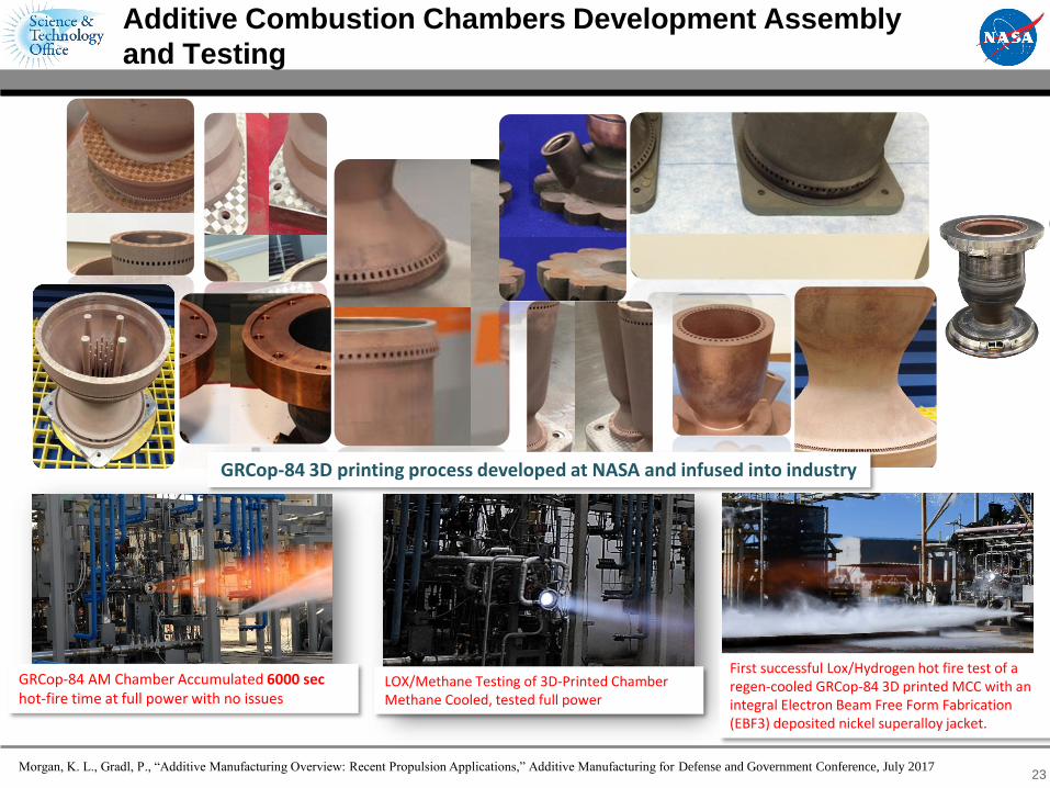
Additive Combustion Chambers Development Assembly
and Testing
GRCop-84 AM Chamber Accumulated 6000 sec hot-fire time at full power with no issues
LOX/Methane Testing of 3D-Printed ChamberMethane Cooled, tested full power
GRCop-84 3D printing process developed at NASA and infused into industry
Morgan, K. L., Gradl, P., “Additive Manufacturing Overview: Recent Propulsion Applications,” Additive Manufacturing for Defense and Government Conference, July 2017
First successful Lox/Hydrogen hot fire test of a regen-cooled GRCop-84 3D printed MCC with an integral Electron Beam Free Form Fabrication (EBF3) deposited nickel superalloy jacket.

SLM GRCop-84 Chamber Testing
24
Science & Technology Office •

25
100# LOX Propane Injector Built 2012Tested Nov 2013 20K LPS Subscale Tested Aug 2013
(3) Subscale Injectors Tested
Methane 4K InjectorPrinted manifolds Tested Sept 2015
LPS 35K InjectorWelded Manifolds Tested Nov 2015
1.2K LOX Hydrogen First Tested June 2013
>7000 sec hotfire
Ref: Brad Bullard Sandy Elam Greene
CH4 Gas Generator InjectorTesting Summer 2017
Additive Injector Development

26
Fuel Turbopump Development and Test
Ref: Marty Calvert / NASA MSFC
Inducer Assembly
Turbopump Assembly
Turbine Stage
Rotating Assembly

27
Liquid Oxygen Pump Development
Pump Housing
Impeller
Stator
Turbine Housing
Turbine Blades
Shaft Baffle
Ref: Derek O’Neal / NASA MSFC

Additively Manufactured Valves Development
28
Main Oxidizer Valve
(MOV)
Oxidizer Turbine Bypass
Main Fuel Valve / Coolant Control Valve
(MFV/CCV)
Fuel Turbine Bypass Valve
Ref: Jim Richard, Dave Eddlemen, Travis Davis / NASA MSFC
Aerospike Engine Multi-Port Valve

29
Large Scale Additive Deposition Nozzle
Technology Development
Morgan, K. L., Gradl, P., “Additive Manufacturing Overview: Recent Propulsion Applications,” Additive Manufacturing for
Defense and Government Conference, July 2017.
Gradl, P. “Rapid Fabrication Techniques for Liquid Rocket Channel Wall Nozzles.” AIAA-2016-4771, Paper presented at 52nd
AIAA/SAE/ASEE Joint Propulsion Conference, July 27, 2016. Salt Lake City, UT.
Gradl, P.R., Brandsmeier, W. Alberts, D., Walker, B., Schneider, J.A. Manufacturing Process Developments for Large Scale
Regeneratively-cooled Channel Wall Rocket Nozzles. Paper presented at 63nd JANNAF Propulsion Meeting/9th Liquid Propulsion
Subcommittee, December 5-9, 2016. Phoenix, AZ.
24+” Dia
Additive Wire-based Channel Closeout
Freeform AM Deposition with Integral Channels
27” Dia
Large Scale Deposition:Blown Powder and Arc Deposition
Ref: DMG Mori Seiki Hybrid

Pull
Fundamental Additive Manufacturing M&P Development
Material Properties
& NDE
Standards & Specs
Certification Rationale
Building Foundational Additive Manufacturing Industrial Base
AMDE Prototype Engine
SLS: RS-25
Methane Propulsion Systems
CCP
Upper Stage Engine
Nuclear Thermal Propulsion
Component Relevant Environment Testing
Lean Component Development
Future Outlook
30

Additive Manufacturing
at Marshall Space Flight Center
31
MSFC Standard and Specification for
Additively Manufactured Spaceflight Hardware

Exploration Systems Development ORION and SLS
Commercial Crew Program (CCP)DRAGON V2
NASA Exploration Programs and Program Partners have embraced AM for its affordability, shorter manufacturing times, and flexible design solutions.
AM in the Human Exploration and Operations Portfolio
32

Standardization is needed for consistent evaluation of AM processes and parts in critical applications.
NASA cannot wait for national Standard Development Organizations to issue AM standards.
MSFC Standard and Specification Release Date: October 18, 2018
• Partners in crewed spaceflight programs (Commercial Crew, SLS and Orion) are actively developing AM parts
• In response to request by Commerical Crew Program (CCP), MSFC AM Standard drafted in summer 2015.
• Draft standard completed extensive peer review in Jan 2016.
• Standard methodology adopted by CCP, SLS, and Orion.
• Continuing to participate with standards organizations and other certifying Agencies.
• Goal is to incorporate AM requirements at an appropriate level in Agency standards and/or specifications.
MSFC Standard and Specification for Additively
Manufactured Spaceflight Hardware
33

Summary: In Space Manufacturing Applications
Conclusions from Systems Analysis of ISM Utilization for the Evolvable Mars Campaign: Why ISM
• Current maintenance logistics strategy will not be effective for deep space missions
• ISM has the potential to significantly reduce maintenance logistics mass requirements by enabling material commonality and the possibility of material recycling and ISRU for spares
• ISM should be considered and developed in parallel with the systems designNASA is actively working to develop ISM capabilities:
• Within Pressurized Volume: Reduce the logistics challenges and keep astronauts safe and healthy in transit and on extraterrestrial surfaces. ISS is a critical testbed.
• External/Free Space - IRMA: Develop new commercial capabilities for robotic spacecraft construction, repair, refurbishment, and repurposing in LEO
• Extraterrestrial Surfaces - Additive Construction: Enable infrastructure to be robotically constructed pre- or post-arrival of astronauts on the extraterrestrial surface, whether that be the Moon or Mars.
To achieve functional capability supporting the Exploration timeline, ISM must work with Exploration systems designers now to identify high-value application areas and influence process.
34

Summary: Space Propulsion System Applications
MSFC has made a major thrust in the application of AM for development of liquid rocket engines ranging from the Space Launch System Core Stage RS-25 engine, to In-Space Class prototype engines, to Cubesat propulsion systems.
• Process development, material property characterization, and component fabrication trials for RS-25 Inconel 718 material applications.
• New design and development philosophy successfully exercised to build AMDE, a prototype in-space class engine incorporating additive manufacturing to reduce costs, schedule and parts counts.
• Designed and additively manufactured > 150 rocket engine parts in 2.5 years• Encompassed every major component and assembly of the engine• Developed and demonstrated capability to additively manufacture with copper. • Data, expertise, and testbed shared with industry for current/future developments
• Capabilities developed through AMDE experience have been applied to small satellite propulsion systems components design and development
NASA MSFC created a Standard and Specification for AM Spaceflight Hardware in response to near-term programmatic demand.
• Shaped the approach to additive parts for current human-rated space flight programs through early release of Draft Quality Standard approach.
• Standard and Specification provide a framework for consistent evaluation of AM Laser Powder Bed Fusion processes, properties, and components.
30
Science & Technology Office •

36