
OVERVIEW AND CHARACTERISTICS OF PIPE CONVEYOR …
44
OVERVIEW AND CHARACTERISTICS OF PIPE CONVEYOR SYSTEMS AND APPLICATIONS A literature study for Transport Engineering & Logistics NOVEMBER 28, 2017 D. HAAK, 4207580 Supervisor: Dr. Ir. Y. Pang
Transcript of OVERVIEW AND CHARACTERISTICS OF PIPE CONVEYOR …

OVERVIEWANDCHARACTERISTICSOFPIPECONVEYORSYSTEMSANDAPPLICATIONS
AliteraturestudyforTransportEngineering&Logistics
NOVEMBER28,2017D.HAAK,4207580
Supervisor:Dr.Ir.Y.Pang

Cover photo courtesy: Continental. Tube Conveyor Belts, the fully closed belt. Retrieved on September 25, 2017 from
http://www.contitech.ru/pages/produkte/transportbaender/cbgindustry/rollgurtfoerderer_en.html

Delft University of Technology
FACULTY MECHANICAL, MARITIME AND MATERIALS ENGINEERING Department Maritime and Transport Technology
Mekelweg 2 2628 CD Delft the Netherlands Phone +31 (0)15-2782889 Fax +31 (0)15-2781397 www.mtt.tudelft.nl
Specialization: Transport Engineering and Logistics Report number: 2017.TEL.8181 Title: Overview and Characteristics of Pipe
Conveyor Systems and Applications Author: D. Haak
Title (in Dutch) Een overzicht en de karakteristieken van buisvormige transportbanden en de
toepassing daarvan Assignment: Literature Confidential: No Supervisor: Dr. Ir. Y. Pang Date: November 28, 2017

TUDelft FACULTY OF MECHANICAL, MARITIME AND MATERIALS ENGINEERING Department of Marine and Transport Technology
Delft University of Technology
Mekelweg 2 2628 CD Delft the Netherlands Phone +31 (0)15-2782889 Fax -1-31 (0)15-2781397 www.mtt.tudelft.nl
Student: Supervisor: Specialization: Creditpoints (EC)
D. Haak Dr. ir. Y.Pang TEL 10
Assignment type Report number: Confidential:
Literature Assignment 2017.TEL.8181 No
Subject: Overview and Characteristics of Pipe Conveyor Systems and Applications
Belt conveyor systems find applications all over the world. In the past decade the development of conveyor technology has enabled the design and application of longer, faster and more efficient conveyors with higher capacity and less environmental impact. Pipe conveyors are more and more used in various industrial production fields.
This assignment is to provide an overview of the characteristics and applications of pipe conveyor systems based on worldwide literature sources. Both existing and the most recent under-construction projects w i l l be surveyed. The survey of this literature assignment should cover the following:
• An overview of the configurations and characteristics of pipe conveyor systems
• A summary of the application fields of pipe conveyor systems
• The trend of development with respect to the scale of pipe conveyor systems
• The innovation and sustainability aspects in pipe conveyor design and applications
This report should be arranged in such a way that all data is structurally presented in graphs, tables, and lists with belonging descriptions and explanations in text.
The report should comply with the guidelines of the section. Details can be found on the website.
The mentor.
Dr. Ir. Y. Pang

2017.TEL.8181
I
Preface
This literature study covers the subject of pipe conveyor systems, with the main focus on the characteristics, configurations and trend of development. The goal of the literature study is to provide a bundled overview of the wide spread information about the characteristics, configurations and trend of development of these systems. Besides that, a summary of application fields will be provided and innovativeness, sustainability and future challenges will be discussed. The underlying perspective of this study is based on intelligent control for transport technology, which will appear in the elaboration on future challenges.
I would like to thank Dr. Ir. Y. Pang for the provided support and availability during this literature study.

2017.TEL.8181
II
Summary The well-known belt conveyor is a transport system that is already known for more than a century. However, the disadvantage of emerging dust and material spillage triggered thoughts to adapt the system to one that completely encloses the transported material. As result the first ideas for a pipe conveyor system, where the belt totally closes in the shape of a pipe, arose in the late nineteen-seventies (Brands). Over the years the concept of the pipe conveyor developed allowing for an increase in length from the first 28m-long pipe conveyor to the currently longest pipe conveyor of 16.4km (Phoenix). Still, the research and development of these pipe conveyor systems is not yet that much evolved and new technologies continuously create opportunities for future improvements. The pipe conveyor belt has a tubular shape except for the head and tail section where it has the conventional U- or V-shape. Just past these loading and discharge sections the belt is folded into a pipe shape by impact idlers and then maintained by supporting idlers. The belt type can be divided in fabric belts and steel cord belts, both with a specific carcass construction to accommodate the required shape. Currently, the most common pipe conveyor configuration is the so-called Japan pipe conveyor where the belt is shaped into the tubular shape with the edges slightly overlapping. This setup was preceded by the zipper concept, with moulded teeth, and the solitude concept, with spring clips. The supporting structure of the Japan pipe conveyor can be divided in an inline arrangement, with six idlers on one side and the offline arrangement, with three idlers on either side of the support frame (Swain et al., 2011). Returning of the pipe conveyor belt can be done as a flat belt or in the same pipe shape, allowing for two-way conveying. Besides that, the pipe conveyor concept allows for multiple feeding and discharging points along the conveying path. All these above described features result in positive as well as negative characteristics of pipe conveyor system which are shown in table 1.
Positive Negative No material spillage High energy consumption Less environmental issues Large required belt width Curved transportation Overload sensitivity Steeper inclination angle Oversize sensitivity Two-way transportation Difficult to repair Low investment costs Backed-up heat Low maintenance costs High operational safety
The above briefly described system developed over the last years allowing for increasing conveying lengths. The first ideas of a pipe conveyor were thought through by Mr. S. Hasimoto (Buchanan, 1985) resulting in a first patent application in 1965. In 1979 the first commercial pipe conveyor system, consisting of two conveyors of 20 and 28 metres, was installed. Shortly afterwards a dedicated research and development department was established in 1982 (Staples, 2002). Recently, Phoenix Extreme Conveyor Belt Solutions (Phoenix) installed a pipe conveyor of 16.4km length. This increase in scale is a result of certain developments over the last years. First of all, the carcass structure, material balance and outer layers of the belt have been adapted with stronger, lighter and lower resistance materials. The pipe conveyor belt has a much greater influence on the system performance that a conventional through belt does (Zhang et al., 2012), which makes these improvements of significant importance. Secondly, the idler and panel design changed over the years. Nowadays the offset idler arrangement is more often used as it better prevents belt trapping and allows for higher belt tension. The idlers themselves have also been altered resulting in larger diameters and outer layers of less cohesive material. Lastly, the drive
Table 1: Characteristics pipe conveyor systems

2017.TEL.8181
III
systems also developed over the years. Application of multi drive combinations and more efficient and powerful engines allowed for longer pipe conveyors. The recent development of fluid couplings offered an even better perspective for the increase of the conveyor lengths as it could improve especially the start and stop dynamics. These developments ensured broadening of the application fields. The most common application fields according to Elecon (Elecon) are the port bulk handling, mining, cement and power plant industries. The chemical and food industry are relatively new with the concept of pipe conveyors. The advantages that these systems can offer in these businesses are of added value and can facilitate better operations. However, advanced systems like pneumatic conveyors are already partly expelling the increasing influence of pipe conveyor in these last two industries. It is expected that the most considerable influence of the pipe conveyor will remain in those first four industries where the particle size distribution is significant. As can be deduced from the above described and is being affirmed by environment related groups (GreenPort) the pipe conveyor concept underlines innovation and sustainability. The innovative aspects are mostly related to the characteristics of the pipe conveyor. The closed belt setup was an innovative idea with respect to the concept present during its initial years. The closed conveying also allowed for easy conveyance of environmentally sensitive materials. Furthermore, the allowance of tight curves and steep inclination angles in combination with long conveyor system can be considered to be innovative as well. Lastly, the possibility of two-way conveying offered an ingenious option to increase the capacity. The sustainability advantage of the pipe conveyor mainly comes forward in the energy consumption of systems with complex conveyor paths (Brands) and the enclosure of the conveyed material. Pipe conveyors for complex paths can eliminate the much energy consuming transfer points while the material enclosure prevents direct, polluting, contact of the material with the environment. Although the pipe conveyor has been developed for decade the future still holds plenty of opportunities to further improve the concept. New magnetic guidance techniques could offer benefits in the coming years resulting in even longer conveyors. Besides that, new structures that require less moving parts have already been developed but not tested extensively enough. Furthermore, the application of artificial intelligence in intelligent pipe conveyor control could result in more efficient systems and thus options to further increase the path lengths. Still, a lot of research is required to apply these new technologies in the pipe conveyor concepts for each application field. Thus, the pipe conveyor has specific characteristics and multiple configurations that distinguish the concept from other conveyor solutions. Developments over the years regarding pipe belts, idlers, panel designs and drive systems have resulted in an increase in scale of the systems. The pipe conveyors are applicable in multiple businesses with the port bulk handling, mining, cement and power plants as main industries (Elecon) and the chemical and food industry as secondary fields. The total concept is still innovative and especially complex systems can be considered as sustainable with respect to other available conveying options. Moreover, the prevention of direct contact of the material with the environment is an important sustainability aspect of pipe conveyors. The future still holds challenges, but recent ideas and more research will potentially grant a continues increase in system scale and more efficient pipe conveyor systems.

2017.TEL.8181
Table of Contents PREFACE ................................................................................................................................................ I
SUMMARY ........................................................................................................................................... II
1. INTRODUCTION ......................................................................................................................... 11.1 GENERAL INFORMATION AND RELEVANCE .................................................................................... 11.2 AIM AND SCOPE OF THE STUDY ...................................................................................................... 11.3 STRUCTURE OF THE REPORT .......................................................................................................... 1
2. CONFIGURATIONS AND CHARACTERISTICS .................................................................. 22.1 PIPE CONVEYOR ASPECTS .............................................................................................................. 2
2.1.1 Basic concept ......................................................................................................................... 22.1.2 Pipe shape .............................................................................................................................. 22.1.3 Idlers ...................................................................................................................................... 42.1.4 Pipe conveyor loading ............................................................................................................ 4
2.2 CONFIGURATIONS .......................................................................................................................... 42.2.1 Belt type .................................................................................................................................. 42.2.2 Closing mechanism ................................................................................................................ 42.2.3 Idler configuration ................................................................................................................. 52.2.4 Returning of belt ..................................................................................................................... 62.2.5 Feeding and discharge ........................................................................................................... 6
2.3 CHARACTERISTICS ......................................................................................................................... 6
3. DEVELOPMENT OF THE PIPE CONVEYOR ....................................................................... 93.1 FIRST IDEAS AND CONCEPTS .......................................................................................................... 93.2 IMPROVEMENTS OF PIPE CONVEYOR ............................................................................................ 10
3.2.1 Pipe conveyor belt ................................................................................................................ 103.2.2 Idler and panel design .......................................................................................................... 113.2.3 Drive systems ....................................................................................................................... 12
3.3 DEVELOPMENT OVERVIEW .......................................................................................................... 13
4. APPLICATION FIELDS ........................................................................................................... 144.1 PORT BULK HANDLING ................................................................................................................. 144.2 MINING INDUSTRY ....................................................................................................................... 144.3 CEMENT INDUSTRY ...................................................................................................................... 154.4 POWER PLANT INDUSTRY ............................................................................................................. 164.5 CHEMICAL INDUSTRY .................................................................................................................. 164.6 FOOD INDUSTRY ........................................................................................................................... 17
5. INNOVATIVENESS AND SUSTAINABILITY ...................................................................... 195.1 INNOVATIVENESS ......................................................................................................................... 195.2 SUSTAINABILITY .......................................................................................................................... 19
6. FUTURE CHALLENGES .......................................................................................................... 216.1 POTENTIAL DEVELOPMENTS ........................................................................................................ 216.2 INTELLIGENT CONTROL ................................................................................................................ 22
6.2.1 Measurements ...................................................................................................................... 226.2.2 Artificial intelligence ............................................................................................................ 23
7. CONCLUSION ............................................................................................................................ 24
BIBLIOGRAPHY ................................................................................................................................ 26
APPENDIX ........................................................................................................................................... 30APPENDIX A: PIPE CONVEYOR PATENT ............................................................................................ 30APPENDIX B: PIPE CONVEYOR APPLICATION EXAMPLES ................................................................... 35

2017.TEL.8181 1
1. Introduction 1.1 General information and relevance The belt conveyor is a transport system that has been in use for more than a century. This system is a well known transport structure that developed in a remarkable rate over the years. However, the disadvantage of emerging dust and material spillage triggered the thought to comprise the transported material completely. As a result, the first worldwide functional pipe conveyor was developed and operated by Japan Pipe Conveyor in the late nineteen-seventies (Brands). This first and basic concept led to extended and improved designs through the years resulting in for example expansion of length, capacity but also increasing energy consumption and more technical difficulties. Although the pipe conveyor is a promising concept, it is still less well known than the traditional belt conveyor. Major industries like the mining, port bulk, power plant and cement industry are increasingly implementing the pipe conveyor concept, but still encounter difficulties in the specific application Therefore, it is of relevance for a large part of the transport industry to gain more insight in the concept of pipe conveyors and the advantages it can offer in the near and long term future. To carry out new detailed studies to improve pipe conveyor systems background knowledge is essential. This report will provide that necessary knowledge to initiate such a study. 1.2 Aim and scope of the study The main aim of this literature study is to provide a bundled overview of the wide spread information about the characteristics and configurations together with the the trend of development of pipe conveyor systems. Additional to this main purpose, the application fields, innovativeness and sustainability of the system are included. The scope of the literature study covers all technical aspects, development of those and applications of the pipe conveying systems, but does not include the dynamics of material and equipment interaction, finite element analyses of belt behaviour and mathematical models regarding the pipe conveyor functioning and behaviour. The main question for this literature study is defined as follows: “What are the characteristics and configurations of pipe conveyor systems and how did the concept develop during the operational years with respect to its scale”. As the underlying perspective of the study is intelligent control for transport technology a sub-question is defined as: “What are the future challenges and how can intelligent control help to tackle these for pipe conveyor systems”. 1.3 Structure of the report The report starts with obtaining insight in the configurations and characteristics of pipe conveyor systems in chapter 2. Thereafter, the development of pipe conveyors is discussed in chapter 3. Subsequently, chapter 4 elaborates on the application fields of the transport system and chapter 5 on the innovativeness and sustainability of the concept. Finally, future challenges are debated in chapter 6 and a conclusion is made in chapter 7. In this way the acquired knowledge builds up towards a full understanding of the pipe conveyor system and the possibilities this concept can offer in combination with intelligent control.

2017.TEL.8181 2
2. Configurations and Characteristics This chapter elaborates on the basics, configurations and specific characteristics of pipe conveyor systems and the difference regarding the conventional belt conveyor. At the end of this chapter insight in the configurations and characteristics is obtained and a distinction can be made between the common belt conveyor and the pipe conveyor. First of all, section 2.1 describes the elemental technical aspects of the pipe conveyor. With the knowledge of section 2.1 different configurations currently available will be discussed in section 2.2. Finally, an overview of the specific characteristics of pipe conveyors is given in section 2.3. 2.1 Pipe Conveyor aspects 2.1.1 Basic concept The pipe conveyor has, as can be deduced from the name, the shape of a pipe surrounded by a certain amount of idlers for most part of the system. Only at the head and tail sections of the transport system the belt has an open U- or V-shape. The loading and discharge of a pipe conveyor is done in the same way as a conventional belt conveyor as the material is dropped on the belt at the tail pulley and discharged by dropping it of at the head pulley. Just past the loading section the belt is folded into a pipe shape. This is often done for the material carrying part as well as the returning part. The above described process is shown in figure 2.1. 2.1.2 Pipe shape Essential part of the pipe conveyor system is the transition of the belt from a flat surface to a closed one. Multiple configurations are available to close the belt, but the most common is the circular so-called Japan pipe conveyor (Woodcock et al. 1987). Section 2.2.2 elaborates more on the possible configurations of belt closing while this section continues with the most common “Japan” configuration. Impact idlers or impact bars support and direct the flat belt into the circular shape till both edges have a slight overlap, which should always be on the top side of the tube. A configuration of these
Figure 2.1: Belt conveyor system (Probelt Global Limited)
Figure 2.2: Belt transition (Fedorko et al., 2012)

2017.TEL.8181 3
idlers is shown in figure 2.2. Often these impact idlers are able to alter their position to adjust the so-called transition length based on belt speed and material properties. The interpretation and calculation of this transition length vary a lot in literature and technical documents regarding the pipe conveyor systems. According to Muhammad E. Fayed and Thomas Skocir in Mechanical Conveyors Selection and Operation (Fayed et al., 1997) a transition length of thirty times the pipe diameter is required to obtain the circular form or to return to the flat belt shape. In the paper Pipe/Tube Conveyors a Modern Method of Coal and Ash Transportation by Frank J. Loeffler (Loeffler, 1995) from the Loeffler Engineering Group a table is provided, partially shown in table 2.1, with transition lengths with respect to the pipe diameter resulting in an average transition length factor of 25 for fabric belts and 50 for steel belts. Continental Conveyor Belt Group (Continental, 2015) stated in a technical document that the minimum transition length requires a factor 30 and 60 for respectively fabric belts and steel-cord belts with respect to the pipe diameter. Lastly, IBT (Brands) provides transition length factors for different material ranging from a factor 25 to 50. Based on these data it is assumed that a transition length factor ranging from 25-35 for fabric belts and 40-60 for steel cord belts is required for a smooth transition to a pipe body.
As can be seen above a second important aspect for the transition to the tubular shape of the belt is the material structure of the belt. The belt requires enough cross rigid stiffness to adapt to and maintain the circular shape but also needs flexibility in the longitudinal direction to follow the shape of the pulleys. To accommodate this specific behaviour for fabric belts, the carcass construction is used. This implies that layers of rubber compound have been aligned between every fabric ply. To prevent spillage of material around the overlapping belt edges, the plies at those edges are often a rearranged in a less stiff alignment for better closure. For the steel cord belts the steel cords are arranged in longitudinal direction with transverse reinforcements on top and below those cords. The top en bottom layer of these belts are both made from rubber compound. The fabric belt is shown in figure 2.3a and the steel cord belt in figure 2.3b.
Fabricbelt Steelcordbelt
Pipediameter[in] Transitionlength[ft] Transitionfactor
Transitionlength[ft]
Transitionfactor
6 13 26,00 25 50,00
8 17 25,50 34 51,00
10 21 25,20 42 50,40
12 25 25,00 50 50,00
14 29 24,86 58 49,71
16 34 25,50 67 50,25
Average 25,34 50,23
Table 2.1: Transition factor (Loeffler, 1995)
Figure 2.3a: Fabric belt (Technical Hub) Figure 2.3b: Steel cord belt (Minkin)

2017.TEL.8181 4
2.1.3 Idlers The idlers are the supporting rolls of the pipe and are present 360 degrees around the pipe. The amount of idlers surrounding the pipe at each side of the supporting frame differs per system and depend on multiple factors, which are later discussed in section 2.2.3. The diameter and spacing of these idlers is calculated based on the size of the pipe conveyor and the material that is being conveyed according to G.A Vaka (Vaka, 1998). They also state that occurrence of belt sagging is partially restrained by the rigidity of the pipe shape allowing for an increased idler spacing and that curvatures and static and dynamic tension conditions influence the spacing too. This determined idler arrangement plays an important role in the stability of the system, which is necessary for flawless functioning. Furthermore, the idlers should support the belt in such a way that the overlap of both edges is maintained as close to the top side of the circular shape to prevent small gaps. Figure 2.1 shows three sections with tubular bars around the pipe that represent these idlers. 2.1.4 Pipe conveyor loading Correct loading of a pipe conveyor is essential for correct operation. To obtain the right alignment of the overlap of belt edges central line loading is important. Besides that, it is crucial to have a constant filling rate as the capacity of the pipe conveyor is determined by the transported volume and not the weight according to IBT (Brands). Contrary to only spillage for a conventional conveyor a pipe conveyor can also jam when the loading capacity is exceeded. Therefore, adequate loading control is necessary for proper functioning of the pipe conveyor. Intelligent control can play an important role to achieve this loading requirements. Based on measurements of alignment and belt speed, the loading chute should could adapt to the right location and speed. Chapter 7 elaborates more on this potential implementation. 2.2 Configurations The pipe conveyor system functions according to the previously described aspects. However, within this main structure different configurations are possible. Based on technical descriptions and previous studies it is deduced that the main configuration differences of the pipe conveyor system are related to the belt type, belt closing mechanism, idlers configuration, belt return structure and feed and discharge points. 2.2.1 Belt type Based on the specifications of the system a fabric or steel-cord belt is used to transport the material, both are shown in figure 2.3a,b. The transverse layer structure of both of these belt type ensures the stiffness that is required to maintain the tubular shape and can differ per application. Besides that, the rubber layers of these belts can alter too. For example, in The evolution of the pipe-conveyor it is described that IBT (Brands) can supply rubber belts in:
- High abrasion resistant (grade 1) - Heat resistant - Flame retardant - Oil resistant - High oil resistant - White rubber
This allows for belt configurations that are suitable for abrasive materials, hot materials, flammable products, oil- and fat containing products and food industry. Without these varying belt type configurations the range of products allowed for conveyance would be limited. 2.2.2 Closing mechanism In Bulk Solid Handling, An Introduction to the Practice and Technology (Woodcock et al., 1987) three different types of closing mechanisms are described that relate to the idea of the pipe conveyor. The first and as stated in Mechanical Conveyors, Selection and Operation (Fayed et al., 1997) first successful closed belt ever is the zipper conveyor designed and manufactured by Stephens-Adamson in the 1950s. This mechanism uses moulded teeth on the belt edges that are meshed and unmeshed by rollers.

2017.TEL.8181 5
However, limited size and problems with nesting and locking of the teeth led to demise of this closing mechanism. During the first years it was only used for complex conveying paths as the lock of both edges was very tight, but nowadays the zipper conveyor can not compete with other configurations. The second design of a closing mechanism is the “Solitude conveyor”. In this configuration the belt edges assembled with spring clips, that hold the belt closed in a tear-drop shape. The tube is supported by outriggers connected to twin independent driving belts, which also support the belt. Idlers can support the bottom of the belt and provide extra guidance. A cross section of the solitude conveyor is shown in figure 2.4. Similar to this closing principle is the flexible Sicon conveyor system described in Sicon® Enclosed Belt Conveyor System (Continental, 2014). Both edges of the belt have vulcanized rubber strips that are folded together by horizontal and vertical guide rollers creating a comparable tear-drop shape. The third, most common and modern design according to Bulk Solid Handling, An Introduction to the Practice and Technology (Woodcock et al., 1987) is the Japan Pipe conveyor. Contrary to the previous described mechanisms, this configuration passes the loading and unloading section as a flat, U- or V-shaped belt. After the loading and unloading the belt is folded into a tubular shape as mentioned in section 2.1.2 by a set of impact idlers. This Japan Pipe Conveyor is usually seen as the first real pipe conveyor system and will therefore be taken as starting point of the pipe conveyor development in chapter 3. 2.2.3 Idler configuration The setup and amount of idlers can vary based on the design and purpose of the pipe conveyor. As the Solitude and Zipper conveyor both do not need idlers or only for support of heavy material transport the idler configurations will be discussed for the Japan Pipe Conveyor system. The most common options are six or three idlers, called the inline and offset arrangement as stated in Mechanical Operations (Swain et al., 2011) and shown in figure 2.5a,b. For the inline arrangement six idlers are mounted on the same side of the frame to prevent any gaps in which the belt could be trapped. The inline arrangement was generally used for long conveyors with thick belts according to the HA200 Idlers design manual (Sandvik, 2008) in the early days of the pipe conveyor. The offset arrangement has three idlers that are placed on either side of the supporting frame
Figure 2.4: Solitude conveyor (Woodcock et al., 1987)
Figure 2.5a: Inline arrangement (Swain et al., 2011)
Figure 2.5b: Offset arrangement (Swain et al., 2011)

2017.TEL.8181 6
allowing for larger rolls and brackets. Nowadays the offset arrangement is more often used for longer conveyors. 2.2.4 Returning of belt The belt of the pipe conveyor can be returned as a flat belt or in the similar pipe shape. A flat return of the belt could safe space in vertical direction and investment costs for total construction. However, a pipe shaped return belt is often used as it prevents cohesive material spillage and it allows for a more compact supporting frame according to G. Boumans in Grain Handling and Storage and IBT (Boumans, 1985), (Brands). In case of a closed returning belt, the cohesive material can only drop op at the tail pulley where it can be collected and returned to the loading chute. Besides these advantages, IBT (Brands) also states that due to the pipe shaped return part conveying of products is possible in two ways resulting in a potentially higher capacity. 2.2.5 Feeding and discharge The basic configuration for a pipe conveyor system consist of one feeding point and one discharge point. However, the pipe shaped belt allows for more than one feed point along the conveying line. A two-way simultaneous conveyance of material is described in The Coal Handbook (Osborne, 2013) with two feeding point and two discharge points. As no transfer stations are required for a pipe conveyor system material can also be loaded into the pipe shaped returning belt to be discharged just before loading the top line again. To be able to implement this return transport of material the return belt has to pass a Z-shaped point as shown in figure 2.6 at the return belt discharge point. 2.3 Characteristics The first and most straightforward characteristic of the pipe conveyor in comparison to the conventional conveyor is the closed belt. As result the material can not shatter or drop of the belt preventing spillage and environmental issues. Besides this main characteristic, Rulmega (Rulmeca) states that curved and inclined transportation are two more important characteristics of the pipe conveyor. As the pipe conveyor systems in general have much smaller idler spacing than the conventional open conveyors, the radius of a curve in a pipe conveyor is primarily determined by the admissible belt stretch as described by G. Lodewijks (Lodewijks, 2001). Besides that, it is stated the pipe conveyor can not run of the idlers since it is locked up in the idlers, but that the restricting factor for the allowable radius is the preservation of the typical cross section to stabilize the pipe within the idlers. As result the required radius for a pipe conveyor system can be only half or one third of the radius for an open belt conveyor system. Important
Figure 2.6: Two-way pipe conveying (Osborne, 2013)

2017.TEL.8181 7
to keep in mind is that buckling of the pipe conveyor due to small radii should always be prevented as it reduces the capacity and could damage the load carrying components of the system. So to implement the horizontal and vertical angle curves the system should have enough strength to withstand this buckling. But if the above described is properly applied, the curved transportation can rule out transfer stations allowing for flexible lay-outs that fit smaller areas. Additional to this curved transportation steeper inclined transportation was stated to be advantageous. Figure 2.7, from the Modern Belt Conveyor Systems by G. Lodewijks (Lodewijks, 2001), shows the conveyor suitability area for inclination degrees in relation to the lump size and capacity at a belt speed of 1m/s. It is shown that a steeper inclination angle of at maximum 30° is possible with a pipe conveyor with respect to the troughed conveyor. This is due to the load distribution of the pipe conveyor and the resulting contact area of the material and belt (Buchanan, 1985). However, this steeper angle in combination with the closed volume is at the expense of the possible lump size. Thus depending on the material that has to be conveyed the steeper allowable inclination angle can be ruled out. If even steeper angles need to be achieved pouch and pocket belts are more suitable as the pipe conveyor can not support the material enough at higher angles.
Figure 2.7: Suitability area at 1m/s (Lodewijks, 2001)

2017.TEL.8181 8
As described before, the possibility of two-way transportation of materials is also a characteristic of the pipe conveyor which grants an option for extra capacity and less space utilization. Furthermore, it is stated by Beumer Group (Beumer Group) that pipe conveyors have low investment and maintenance costs and a high operational safety. These three advantages are also confirmed by Babcock & Wilcox (Babcock & Wilcox) and Dimatteo (Dimatteo) in their description of pipe conveyors. Therefore, these advantages could be seen as characteristics of the pipe conveyor system. Lastly, a high energy consumption, a larger required belt width, overload and oversize sensitivity, more difficult repairs and backed-up heat in the case of hot bulk material are disadvantages or negative characteristics as stated by Franz Kessler (Kessler, 2003). To have an overview of the above described characteristics both the positive and negative ones are shown in table 2.2.
Characteristics Pipe Conveyor Systems Positive Negative No material spillage High energy consumption Less environmental issues Large required belt width Curved transportation Overload sensitivity Steeper inclination angle Oversize sensitivity Two-way transportation Difficult to repair Low investment costs Backed-up heat Low maintenance costs High operational safety
Table 2.2: Characteristics pipe conveyor systems

2017.TEL.8181 9
3. Development of the pipe conveyor This chapter describes the trend of development of the pipe conveyor with respect to the increasing scale. It starts with an elaboration on the first ideas and concepts of these systems in section 3.1. Then section 3.2 continues with the improvements over the years that resulted in the longer systems present today. Lastly, section 3.3 summarizes the factors that resulted in these improvements with a brief time line showing an overview of some major milestones. 3.1 First ideas and concepts According to C. Buchanan (Buchanan, 1985) the first ideas to form a flat belt into a pipe shape were already under investigation by Mr. S. Hasimoto in 1959. Mr. Hasimoto started this evolution of closed conveyor systems based on the zipper and tear drop shape ideas described in section 2.2.2. This resulted in a basic design and patent application in 1965. The basis for this patent was the ability to form a through belt conveyor into a pipe shape using a unique belt construction and special pipe forming idlers according to P. Staples (Staples, 2002). Figure 3.1 shows the patent with different configurations that was already requested in 1965 by Kunio Hashimoto (Hashimoto, 1967). These figures are enlarged in Appendix A: First pipe conveyor patent.
Figure 3.1: JPC Patent first pipe conveyor (Hashimoto, 1967)

2017.TEL.8181 10
It can be seen in figure 3.1 that the basic components, as described in section 2.1, are present in this first patent. Remarkable is the presence of the zipper closing mechanism that was invented and used by Stephens-Adamson in the 1950s but also partly rejected shortly afterwards. Besides that, the illustrated idler configurations do not fit the modern inline and offline configuration. The first pilots with this concept were only done in 1970 because the details to maintain a pipe shape were not yet understood well enough. Mr. Hashimoto persisted on his basic idea and drew the Bridgestone Rubber Company into the development of a suitable pipe conveyor system in exchange for manufacturing rights. A second and third trial took place in respectively 1975 and 1976 resulting in a successful straight level pipe conveyor. In 1977 a concept was developed that allowed for steep inclined transportation. The first three major difficulties that were overcome with this development in these first seven years were the following according to C. Buchanan (Buchanan, 1985):
- Developing a belt with relative rigidity to allow a flat belt to be formed and maintained in a pipe shape.
- Developing a technique for correcting misalignment and twisting. - Developing the best arrangement of carrying and controlling the pipe belt.
After these successful trials the first commercial pipe conveyor system was installed at Kitakyushu Sand Co-op in Japan in 1979. It consisted of two 300mm diameter conveyors of 20 and 28 meters in length, which are still in operation. Shortly after this first application the Japan Pipe Conveyor Company was formed in 1982, which also resulted in a dedicated research and development department for pipe conveyor systems (Staples, 2002). 3.2 Improvements of pipe conveyor As stated above, the first working commercial pipe conveyor had a maximum length of 28m. Currently, the longest pipe conveyor already reaches up to a length of 16.4km with 8,172m centre distance according to Phoenix Extreme Conveyor Belt Solutions (Phoenix). Although research and development in pipe conveyor systems has only been been carried out for a few decades, significant improvements have been established to allow for this increase in length and capacity. Each of these advancements will be discussed in the continuation of this section. 3.2.1 Pipe conveyor belt A critical development resulting in the increasing length of the pipe conveyor is the adaption of the belt. As stated by Y. Zhang and R. Steven (Zhang et al., 2012) the pipe conveyor belt has much greater influence on the system performance than through belt does with leading factor for this performance being the belt stiffness. When the belt is rolled into the pipe shape the intrinsic bending stiffness turns into the contact pressure on the surrounding idler rolls. As the higher belt stiffness results in higher contact pressure the stability of the pipe belt increases with better resistance against twisting and collapsing. However, this goes of the expense of increased power consumption and higher belt tension. Therefore, it is essential to design a belt based on a balance of these factors for each application individually. The research in pipe conveyors resulted in experimental and numerical ways to determine this best fitting stiffness. During the first years of the pipe conveyor these methods for stiffness determination were not available or based on analytical simplifications and basic experiments resulting in not optimal stiffness calculations. Consequently, these first pipe conveyors had less stability and could therefore not be as long and fast moving as the better adjusted belts of the present days. The ways to obtain this mentioned, balanced stiffness also developed during the years. According to Teijin (Teijin, 2016) the first reinforcements of belts consisted of aligned cotton fibres, followed up by polyester and polyamide fibres. However, these reinforcing fibres have the serious drawback of a low stiffness module. This low stiffness module led to too much elongation of the belt for longer pipe conveyors. Teijin illustrates this with showing that for a 5km conveyor installation, 10km looped, an elongation of 3% already results in 300m of excess belt that has to be taken up.

2017.TEL.8181 11
The alternative reinforcement, allowing for longer belts, was the implementation of steel chords. These chords were first equally aligned in longitudinal direction over the total belt width permitting for longer belts relative to the fibre reinforced belts. However, research in these steel chords structures showed that specific orientations could accomplish an even better stiffness balance. Conveyor Dynamics Inc. and Veyance Technologies Inc. (Zhang et al., 2012) developed a belt with three zones; a centre tension carrying zone with steel cords, an overlap zone with reduced number of steel cords and a junction zone with no steel cords. Another example is provided by Phoenix Extreme Conveyor Belt Solutions with the Phoenopipe steel cord belt (Phoenix). In this belt the separate, non-interwoven cords are spaced optimally satisfying the specific requirements of a pipe conveyor system. Due to this optimally spaced cords the belt greatly ups the restoring force and thus the trackability. These improved characteristics of the belt repeatedly allowed for longer belt conveyors and higher belt speed resulting in more capacity. Although the steel-cord belts granted a remarkable increase in conveyor length it also required required a higher energy consumption due to its high mass. Solution for this high mass steel cords could be the aramid fibres as stated by Teijin and G. Lodewijks (Teijin, 2016), (Lodewijks, 2011). Aramid fibres are almost as strong as steel, but a lot lighter. Therefore, the mentioned balanced stiffness could be achieved with a large decrease of required power. Lodewijks verified this weight reduction with a case-study of belt installation in South-Africa. Replacing this steel-cord belt with an aramid reinforced belt resulted in approximately 15% less moving mass. To compare the above described materials that allowed for longer pipe conveyor belts over the years figure 3.2 shows the belt elongation and recommended take-up percentage of centre distance with different reinforcement materials. A last improvement in the belt design is not in the carcass structure but in the running layer of the belt. These rolling layers cause resistance when rolling over the idlers resulting in a loss of up to 60% driving energy for long conveyors according to Teijin (Teijin, 2016). Over the years the outer layer of the belt has been replaced by low rolling resistance rubbers and even super low rolling resistance compounds. A recently implemented running layer compound is sulfron, an aramid-based rubber ingredient produced by Teijin that reduces hysteresis. In the same case-study as mentioned above Lodewijks (Lodewijks, 2011) showed that a combination of aramid reinforced fibres with sulfron in the running layer could reduce the belt power consumption by 25% again allowing for longer pipe conveyor systems and higher belt speed. 3.2.2 Idler and panel design Besides the belt improvements, the panel and idler design have also been subject to changes. The original design of the pipe conveyor started with a panel that had six idlers on one side, called the inline arrangement as described in section 2.2.3. As a result, the belt often got trapped between the idlers
Figure 3.2: Reinforcement comparison (Arts, 2009)

2017.TEL.8181 12
causing belt damage. This complication limited the length of the pipe conveyor significantly. Nowadays, the configuration of three idlers on either side of the panel, the offset arrangement, is used more and more. Although the inline arrangement was considered better suited for longer conveyors, the offset arrangement is now taking over. As trapping of the belt happens less often with the offset arrangement higher belt tension can be taken up, which comes with longer pipe conveyors. The current longest pipe conveyor in the world of 16.4km supports this statement as it uses the offset arrangement. In addition to the panel design, the idler design itself is also a length restricting factor. Due to the inline arrangement and the consideration that pipe conveyors were for low capacity and short lengths, the idler diameters were in the range of 60 to 80mm (Staples, 2002). However, research of L.K. Nordell (Nordell, 1989) showed that the power drawn by a conveyor is related to the idler diameter, with less required power for larger diameters. Therefore, now larger diameter idlers are tending to be used to increase the maximum length of the pipe conveyor. Furthermore, the bearings of the idlers improved over the years and the material of which the idlers are made became less cohesive with the belt material. These improvements both resulted in less energy consumption allowing for longer belts and higher capacities. 3.2.3 Drive systems Another development for pipe conveyor systems has taken place in the drive system design and selection of the drive itself. The most conventional drive system has a drive pulley and a tensioning pulley, but as described by G. Lodewijks (Lodewijks, 2001) the addition of an intermediate drive can save up to 30% in belt tension allowing for longer systems. Disadvantage of this multiple drive configuration is the required exact coupling of the individual drives. This conventional and multiple drive configuration are shown in figure 3.3. The pulleys have also been adapted over the years with small shape changes and improved cover material. Most of the pulleys are now completely covered with vulcanized rubber to prevent slipping of the belt. Furthermore, Cisco-Eagle (Cisco-Eagle) states that a drive pulley that is larger in the middle helps to keep the belt in the centre, which improves the performance of the drive. Lastly, pulley selection for certain systems has became more accurate as result of improved system simulations. A better suited pulley improves the system performance and thus extends the maximum conveyor length and capacity. At last, the engines and couplings have also been improved over the years. More efficient engines with variable frequency drives have been developed resulting in more available power to drive longer pipe conveyors and allow higher belt speed. Besides the more efficient use of the power, the available power itself also increased with the same result. A more recent development that contributed to longer pipe conveyor systems is the voith fluid coupling, which is able to transmit rotating mechanical power with high efficiency. According to Voith Engineered Reliability (Voith) no other component contributes more to smooth belt operation. It is also stated that extremely long and heavily loaded belt conveyors can start up and accelerate reliably when equipped with these voith fluid couplings. These same couplings also enable for better cooperation of multiple drive pulleys, providing a solution for the required exact alignment of the individual engines with active load sharing. Thus, better combinations of drive pulleys, improved engines and advanced couplings contribute to the possibility to further upscale pipe conveyors over the years.
Figure 3.3: Conventional and multiple drive system (Lodewijks, 2001)

2017.TEL.8181 13
3.3 Development overview Thus although the pipe conveyor system concept is relatively new, it has already been subjected to a lot of development resulting in the increase of conveyor length from an initial 28m to 16.4km recently. The first ideas of troughed conveying originated back to 1959 by Mr. S. Hasimoto. Shortly after the installation of the first commercial pipe conveyor system in 1979, JPC established a research & development department that led to the first improvements to increase the possible conveyor length. In the subsequent years developments have taken place in the areas of conveyor belts, idler and panel design and drive systems. Together these advancements allowed a gradual increase in conveyor length. Figure 3.4 shows a brief timeline with the most important milestones in the development of the pipe conveyor systems with respect to conveyor length. Figure 3.5 shows the amount pipe conveyors sorted per length from 1978 till 2002, with the striking observation that short pipe conveyors have still been installed much more than longer ones. Although more recent specific data is not available about pipe conveyor length, it is expected that the amount of long conveyors increased as result of the above described developments.
Figure 3.4: Timeline major milestones pipe conveyor development (Conveyor Dynamics Inc.)
Figure 3.5: Pipe conveyor length (Staples, 2002)

2017.TEL.8181 14
4. Application fields This chapter will further elaborate on most of the different application fields of pipe conveyor systems. For each field the corresponding characteristics will be mentioned. Furthermore, two examples for every field will be provided. An overview with more examples ordered based on length scale is provided in Appendix B Pipe conveyor application examples. As according to Elecon (Elecon) and Beumer Press Releases (Beumer Press Releases) the port bulk handling, mining in combination with steel, cement and power plant industries are the most common application fields these will be discussed in section 4.1 till section 4.4 respectively. The chemical and food industry are two application fields that are relatively new with the pipe conveyor concept and will be both be discussed in section 4.5 and section 4.6 respectively. 4.1 Port bulk handling Bulk handling and container handling are two of the major activities that take place in the port industry. Pipe conveyor systems are applied on big scale in the bulk handling industry. Only the port of Rotterdam already had a throughput of 461.2 million tonnes of bulk in 2016 of which 82.3 million tonnes were dry bulk (Port of Rotterdam Authority, 2017). The pipe conveyor system is mainly useful to transport this dry bulk. The two most important characteristics of the pipe conveyor that provide an advantage in port dry bulk handling are the ability to contain material dust and spillage and the flexibility of the system. Port areas are often close to populated areas resulting in restricting rules with respect to diffusion of materials. Especially the handling of dry bulk encounters considerable dust dissipation during transport with conveyors. As described before in section 2.3 the closed conveyor can prevent this scattering of dust during the transport except for the loading and unloading area. Furthermore, the curved transportation eliminates transfer points, which are significant contributors to the arise of dust. Besides that, material spillage is also prevented resulting in less waste and higher capacity. Lastly, the flexibility of pipe conveyors can be convenient as the port areas are often closely spaced and bulk storage fields are often not perfectly aligned. So again the allowance for curved transportation is a useful characteristic of the pipe conveyor systems. An example of a pipe conveyor system specific for transportation within the port area is the second pipe conveyor installed in the Netherlands. Swarttouw Stevedoring Company in Rotterdam installed a 120m long pipe conveyor that could transport phosphate and petroleum cokes. It provided a transport system in which contact of the material with the environment around Rotterdam and material spillage was minimized (Brands). Still, most of the ports use open belt conveyors to transport their bulk within the bulk terminal areas and only pipe conveyors to transport their bulk immediately to plants or warehouses located inland. Example of a longer inland pipe conveyor that connects to a harbour is the 3km pipe conveyor in the port of Callao transporting zinc, copper and lead concentrates from warehouses to the terminal (BulkInside). However, stricter environmental rules and increasing shortage of space due to bulk handling growth push harbours to examine the possibilities for pipe conveyors within their bulk handling areas (GreenPort). 4.2 Mining industry The second industry in which the pipe conveyor plays a role is the mining industry, which also includes the steel industry as those are most of the times combined. Most of the mines or excavation sites are not located next to the processing plant or storage area. To transport the material from the mines to these secondary locations pipe conveyors can be of great use. Different from the conveyors in the port areas, these pipe conveyors often have to bridge longer distances with horizontal inclinations or curves as result of the mine locations. Similar advantage is the protection of environmental sensitive areas and material spillage reduction. The material spillage prevention is of even larger importance as the pipe conveyors cover longer distances (BulkInside). Besides that, the pipe conveyor most of the times replaces material transport by trucks. This results in less occupation of the roads by these trucks and

2017.TEL.8181 15
relative emission reduction if the pipe conveyor is long enough. Though, one will only find the pipe conveyors in mining industries with limited lump size particles. According to R. A. Carter (Carter, 2015) pipe conveyors are hardly applied in for example hard rock mines as they can not convey the particle size that is often present. Therefore, the pipe conveyors will be more suitable for mineral sand or metal concentrate mines. A first remarkable example is the skyline mine pipe conveyor of 3.4km in Utah. This pipe conveyor transports 1270 tonnes of crushed coal from the mine site to the train loading facilities. The total system has 22 horizontal and 45 vertical turns while overcoming an elevation drop of 172m. Upon initial installation this pipe conveyor was the highest capacity and second longest steel cord pipe conveyor in the world. Research showed that the replacing the conventional truck transport by this pipe conveyor improved the efficiency for maintenance and operations by a factor 9 (Minkin et al.). Although longer and higher capacity pipe conveyors have been installed afterwards it still remains as remarkable material handling system. Another example of a pipe conveyor in the mining industry is the 5.3km long conveyor in Papua New Guinea (FLSmidth). It transports gold ore from the mine site to the process plant. All curves of the system together add up to 719 degrees, being two full turns of a circle. Besides that, the system first overcomes an elevation drop of 520m to the river valley continued by a rise of 300m to the discharge point at the end. To overcome these height differences, it was chosen to install four motor of 630kW in twin configuration on both the tail and head end. This resulted in a capacity of 7800 tonnes of ore per hour with a pipe diameter of only 300mm and belt speed of 4m/s. 4.3 Cement industry The third major industry, the cement industry, uses the two-way transfer and dust suppression characteristic of the pipe conveyor the most. Often the cement plants are fed with limestone and aluminosilicate material via the upper run of the pipe conveyor, while clinker, a cement product, is fed back via the lower run of the pipe conveyor. This clinker consists of larger particles but also of a lot of small particles that are sensitive to vibration. Therefore, the closed surface of the pipe conveyor is necessary for the confinement of this dust in the two-way system or the single way system when only clinker is transported to the cement mills. Another difference of the pipe conveyors in this industry is that often a heat resistant belt is required as the clinker is transported immediately after the sintering of the raw materials as mentioned by Sempertrans (Sempertrans) and Dunlop Conveyor Belting (Dunlop). A first example that shows the use of the two-way transfer option and heat resistance of the pipe conveyor is the earlier described, currently longest pipe conveyor in the world of 16.4km (Phoenix). The lower run of this pipe conveyor, designed by Phoenix, transports raw coal and limestone from the ship unloading station to the cement plant, while the upper run transports the clinker at 80º Celsius back to the ship loading station. This belt is built underneath the streets of Lima and overcomes an altitude drop of 164m with the smallest curve radius being 300m. Figure 4.1 shows the remarkable setup of the PHOENOPIPE® pipe conveyor.
Figure 4.1: PHOENOPIPE® pipe conveyor (Phoenix)

2017.TEL.8181 16
As second example of the application of pipe conveyor systems in the cement industry can be found at the cement factory Portlandzementwerk Wotan H. Schneider. For this cement factory Beumer Group designed a 213m-long pipe conveying system to transport the clinker to the cement mill (Beumer Group II). Since the pipe conveyor was completely enclosed, preventing drop of material, and small radius curves were possible it could be build above the working area of the plant crossing roads and walking paths. Besides that, the standard characteristic of dust suppression was important for the employees and people living in the vicinity. As additional, innovative feature low-noise bearings and electric motor were used in this design to limit the noise to a minimum to create an even more pleasant environment for these employees and close living people. 4.4 Power plant industry In this last major pipe conveyor industry, the conveyor systems are mainly used to transport fuel to the power plants. However, in this industry the two-way option can also be used to transport the residue of the power plant, like fly or bottom ash, back to storage areas or other transport commodities. To keep these toxic residues away from contact with the surrounding environment the closed conveying option of the pipe conveyor plays again an important role. But besides this pollution prevention the closed conveyor also prevents the flammable ashes as stated by Powermag (Douberly, 2007) to spread in the air and ignite. A last advantage of the pipe conveyor in the power plant industry is the ability to easily control the feed and discharge of the plant. A first example of this application of the pipe conveyor is the 6.9km-long pipe conveyor that supplies the Jindal Super Thermal Power Plant in India with coal from the mines (Jindal Power Limited, 2009). This pipe conveyor is build on an elevated structure, which in combination with the closed conveying does not affect the existent roads and nature too much. As second example the pipe conveyor of 475m centre distance that supplies the Linz AG power station with fuel shows an even more inventive use of the pipe conveyor (Beumer Group I). Instead of the common fuel like coal it transports household and industrial waste as well as sewage sludge from the treatment plant to the power station. Both stations are located within a public area, which makes the closed design of the pipe conveyor important. The tubular closed shape prevents drop of the waste, unpleasant smells and pollution of the environment. Besides that, a height difference of 24 metres is bridged from the feeding to the discharge point. Similar to the pipe conveyor at the Portlandzementwerk cement factory special idlers, low-noise bearings and correct conveying speed are used to improve the environment of the employees and people living in that area. 4.5 Chemical industry More recent application field of the pipe conveyor is the chemical industry. The closed transport belt ensures that the chemicals do not degrade as they do not come in contact with the environment. Furthermore, the systems can not be dangerous for employees that work in the same area due to the closed belt. Based on the chemicals that need to be transported the belt and supporting structure need treatment with chemical resistant material to prevent corrosion or with heat resistant material to prevent ignition of the chemicals or belt damage. As stated by Continental Belting (Continental Belting) the chemicals are often very effective in their nature and therefore their transport need a high level of automation and accurate processing. As a result, the pipe conveyors in this industry are mostly of small scale with very precise loading and unloading stations. An even newer development in the chemical industry that challenges the implementation of pipe conveyors is the vacuum conveyor. Because vacuum conveyors are not suitable for particles with varying size distribution it is not yet really suitable to apply in the previously described industries, but in the chemical industry it already offers a valuable replacement for the short pipe conveyors (Powder Bulk Solids).

2017.TEL.8181 17
Good examples are the two parallel pipe conveyors of 6.2km with 102m height difference used by Kailin Fertilizer Co. in China (Sichuan Zigong Conveying Machine Group). A low rolling resistant belt was installed in these configurations to safe energy and enable the relative long length of the system. According to research described by Yijun Zhang (Zhang et al., 2012) this low rolling resistance belt saves about 4 million kWh per year compared to a conventional pipe belt based on 3.2 million metric ton annual tonnage. The pipe conveyors were introduced as a pro-environment project in 2012 as the discharge of phosphogypsum residue could now be taken from wet, being discharged in the Wujiang river, to dry, being discharged in a dedicated storage. The closed transportation of the material was of importance as the residue has some weak radioactivity and contact with the environment was therefore harmful. A second example described by Conveyor Dynamics (Conveyor Dynamics, 2016 May) is the combination of two pipe conveyors that transport raw calcium sulphate to the same processing plant. Both pipe conveyors cover a length of 1.2km and transport the sulphate 205m upwards with a 300m horizontal curve just after the inclination, shown in figure 4.2. The advantage of the pipe conveyor for this particular transport is mainly the shielding of the material of different kinds of weather and the allowance for the steep inclination of the belt. 4.6 Food industry The food industry has already known and used belt conveyors for a relatively long time. However, the application of pipe conveyors is promising for situations in which the conventional belt conveyor is not competent. The closed pipe conveyor concept is particularly useful in the raw food industry where temperatures, humidity or contamination of product are concerned. When products that form the basis of food are transported from their agricultural site to a processing plant the pipe conveyor can be a useful asset. Different from the other application areas it is very important that the belt remains hygienic, which requires extra cleaning systems. Furthermore, the belt material should not influence the taste and structure of the product. Pipe conveyors can in that sense be beneficial for the hygiene as material is contained within the belt and cannot end up between the system components. Road Engineering (Road Engineering) introduces the wrap conveyor as a more advanced pipe conveyor concept that fits the food industry better. It combines the concept of the enclosed pipe conveyor with a resin material belt that is hygienic, easy to clean and allows for inclination angles up to 78° if small tooth-shaped baffles are implemented. They state that the wrap conveyor is the best for direct transportation of raw products like sake race, coffee beans, grain and fruit in food manufacturing processes. Remarkable is the application of more and smaller idlers in their wrap conveyors to support and guide the pipe, an example can be seen in figure 4.3.
Figure 4.2: Parallel pipe conveyors Kailin project (Conveyor Dynamics Inc.)
Figure 4.3: Road Engineering wrap conveyor (Road Engineering)

2017.TEL.8181 18
Still, similar as for the chemical industry more innovative systems as pneumatic conveyors or tubular drag or screw conveyors are already partly expelling the increasing influence of the pipe conveyor in this application field. Steeper angles and faster transportation within the processing plant can be achieved with these concepts, resulting is a higher performance of the overall system. Besides that, the conventional open belt conveyor, most of the time with standing baffles, is often sufficient to transport solid foods within the plants. So the application of pipe conveyors will mainly be limited to materials that easily scatter or have to be transported via outside environment. Despite that IBT, FFE Minerals and Boumans in Grain handling and storage (Brands), (FFE Minerals, 2013), (Boumans, 1985) mention the application of their pipe conveyors in the food industry, no detailed illustrative cases can be found in affiliated literature with enough technical details. However, the Liftvrac lifting conveyor (Liftvrac) is a system based on the pipe conveyor concept that is specific for the food industry. This system is a small scale pipe conveyor that can transport the products under a high inclination angle. Using a polyurethane conveyor belt the texture of the product can not be damaged and the high hygienic standards can be met. The setup of the system is shown in figure 4.4.
Figure 4.4: Liftvrac pipe conveyor lifting equipment (Liftvrac)

2017.TEL.8181 19
5. Innovativeness and Sustainability This chapter briefly outlines the innovative and sustainable aspects of the pipe conveyor systems. Most of these aspects have already been disguisedly introduced before, but will be now be restated in the context of these terms. Both innovativeness and sustainability will be elaborated on in section 5.1 and section 5.2 respectively. In each section a comparison will be made with the conventional belt conveyor. However, due to the novelty of the pipe conveyor concept limited data is available resulting in only restricted proclamations. 5.1 Innovativeness The innovative aspects of the pipe conveyor are mostly the same as the characteristics described in section 2.3. Although closed conveying was already tried out with moulded teeth and closing mechanisms the pipe conveyor was the first widely applicable alternative that was more environmental acceptable than the conventional belt conveyor. The pipe conveyor concept obviated the need for enclosure structures of the belt and diminished the spillage of material and environmental damage that the transport could cause. However, as the transition parts of the pipe conveyor are still open it does not differ from the conventional belt for that part of the system. Besides the spillage and environmental damage reduction, the closed conveying also offered an option to implement conveyor technology in the transportation of environmentally sensitive materials as food and degradable raw materials allowing for faster transportation with higher capacity. Furthermore, the flexibility of the pipe conveyor is an innovative aspect with respect to longer conveyor technologies. As shown by figure 2.7 the pipe conveyor permits steeper inclination angles with respect to the belt conveyor. Pouch and pocket belts and pneumatic systems do allow for even much steeper angles, but in conveying length these systems stay behind the pipe conveyor. Therefore, the possibility to implement steeper inclination angles in combination with long length belts can be seen as an innovative. Likewise, the small radii for curves in the pipe conveyor system signifies innovativeness as the systems does not require transfer stations anymore and thus reduces space utilization. The combination of this tight curves with the allowed inclination makes the pipe conveyor system even more innovative in the field of long conveyor systems. A last innovation that particularly resulted from the adaption of conventional belt conveyor concept to that of the pipe conveyor is the two-way transportation option. The return part of the belt can also be used to transport the same, processed or completely different material back to any discharging place along the belt. The fact that in this way the capacity of the belt system can be raised or even doubled without extending the system or adding a supplemental one can be considered as innovative.
5.2 Sustainability Sustainability has multiple definitions, but for this section the description of the World Commission on Environment and Development is used: “Sustainability is the development that meets the needs of the present generation without compromising the ability of future generations to meet their needs.” (World Commission on Environment and Developments, 1987) First of all, the pipe conveyor belt does not surpass the life of a conventional belt according to IBT (Brands) with a possible average lifetime of 10 to 15 years if no mechanical damage occurs. However, advantage of the pipe conveyor is that this damage does occur less often then with the conventional systems. For the conventional systems misalignment of the belt can result in contact with supports and beams leading to mechanical damage. For the pipe conveyor this will not occur as long as the pipe shape is maintained. At the transition of the belt this mechanical damage is also not usual as the belt will enter and leave the hexagon configurations on the centreline of the pulley. However, as the belt lifetime is strongly dependent on the material conveyed, its abrasiveness, hardness, size and shape, impact at loading point and flow velocity (Chandrasekaran, 2017) it is not possible to make an exact numerical

2017.TEL.8181 20
comparison. Therefore, the belt of a pipe conveyor is considered slightly less sustainable than the belts of conventional conveyors. Still it is expected that the continues developments of the belts, as for example implementation of aramid fibres as described in section 3.2.1, will grant increasing lifetime. As then less belts will be amortised the environment will be less contaminated increasing the sustainability. Secondly, the energy consumption of pipe conveyors is directly related to the sustainability of these systems. As stated by amongst others IBT, Franz Kessler and G. Vaka (Brands), (Kessler, 2003), (Vaka, 1998) the energy consumption of the pipe conveyor system by itself is a bit higher. Due to the extra amount of idlers, bigger load on these idlers, transformation of the belt into the pipe shape and product filled pipe while negotiating the hexagon configuration extra energy is required. However, the flexible curve and inclination characteristics of the pipe conveyor can result in better energy performance for the overall system. Due to these curve and steeper inclination allowance the normally transfer points can be eliminated. This could result in less energy consumption then when the system is build with multiple conventional conveyors with transfer constructions in between. As accessory the need for maintenance also decreases when these transfer points are eliminated. Therefore, as expressed by IBT (Brands) the larger the number of conveyors needed to cover the trajectory, the better and more sustainable the position of the pipe conveyor will become with respect to the energy consumption and maintenance. Lastly, a directly related aspect of the pipe conveyor system to sustainability is the totally enclosed system. GreenPort (GreenPort) also mentions the implementation of pipe conveyors in their article about bulk cargo handling cleaning up their act to achieve more sustainable operation. Although the pipe conveyor prevents only material spillage in the local environment at the moment of conveying, in the long term spreading to the global environment is also precluded. As continuation of the above described, the elimination of transfer points also plays a role in the environmental pollution. These transfer points are major contributors to material spillage into the environment of belt conveyor systems. Therefore, the possibility of curved pipe conveyor paths and thus the phasing out of transfer points creates a more sustainable system. Especially for the transport of environmentally dangerous materials as radioactive products like the example in section 4.5 the pipe conveyor is offering a sustainable solution that takes into account the environment for future generations.

2017.TEL.8181 21
6. Future challenges This chapter elaborates on some of the challenges that still remain for the development of the pipe conveyor concept. Although relatively much improvements have been made in a short period time, there are still ways to advance these systems. Implementation of intelligent control for this transport technology could be an option to further enhance these systems. Section 6.1 will first describe potential developments that are currently under investigation. Subsequently, section 6.2 elaborates on the possibilities to implement intelligent control based on the findings of this study. 6.1 Potential developments As stated before and confirmed by Shuang Wang et al. (Wang et al., 2016) in their paper about a low resistance permanent magnet pipe belt conveyor the pipe conveyor has numerous advantages but also a lot of drawbacks. It is stated that the large number of movement parts, high maintenance costs, large operation resistance and increased friction between the idlers and the belt may cause problems. Besides that, the conveyor system on its own still uses more energy than the conventional conveyor belts. Therefore, conveying without idlers is currently the focus of the low resistant belt conveyor studies as that could reduce these drawbacks the most. Magnetic guidance of the pipe belt could offer a suitable setup to reduce mechanical friction and operation resistance of the belt. An applicable concept provided by Shuang Wang et al. with 6 permanent magnets and a pipe magnetic conveyor belt is shown in figure 6.1 (Wang et al., 2016).
Simulation models and analyses showed that the under the right air gap conditions the magnetic system could achieve the required stability with very low resistance. However, it is also stated that fluctuating magnetic flux densities could result in deviation of the conveyor belt running. Therefore, anti-deviation devices should be installed to accommodate the functioning of the system. Overall the magnetic guidance is a promising concept, but further research is required to acquire exact knowledge of system behaviour in different environments with varying products. A second option to eliminate movement components and thus reduce the operational drawbacks is to integrate the delivery and return belt if the commercial application does not need a two-way transportation system. In 2013 the Bosmin Coaxial Pipe Conveyor concept was proposed incorporating the delivery and return conveyor into a single bi-directional pipe (Hastie et al., 2013). This was achieved by using flexible helical idler springs to support and contain the belt sections as shown in figure 6.2. It appeared that this system could negotiate curves down to 25:1 curve radius/pipe diameter, had a relatively light structure, low full load running resistance and short transition sections. However, Bosmin did not progress a detailed design beyond their standard coal demonstration model resulting in the disruption of the concept.
Figure 6.1: Magnetic pipe conveyor support structure (Wang et al., 2016)

2017.TEL.8181 22
Still, this system could constitute a concept that allows for increase in conveyor length in the future. As the belt is tightly guided misalignment and twisting of the belt is better prevented resulting in less complications with high belt tension for long pipe conveyors. Besides that, the compact structure in combination with the possible tight curves requires less space utilization. Future improvements on the existing frame could be achieved by implementing the low rolling resistance bearings and belts as previously described in section 3.2.2. Similar to the magnetic guidance concept further research of the application of this concept in different fields is required to gain the necessary knowledge to determine whether this could be a promising system in the future. 6.2 Intelligent control The concept of intelligent control is already known in the conveying industry with different applications as speed, force and alignment monitoring. These monitoring operations have separately been combined with basic software that could improve the functioning of the pipe conveyor. However, if a combination of speed, force and alignment monitoring could be integrated with artificial intelligence, the operation and loading of pipe conveyor systems could potentially be improved. If the speed of the belt is not correct, too much belt tension and misalignment could be a result and vice versa. The system should acquire data and then identify, localize and solve abnormalities. Depending on the combination of the acquired measurements the system should decide what appropriate actions to carry out. This kind of intelligent belt conveyor monitoring and control has already been proven to have a high success potential for conventional belt conveyors (Pang, 2010) and could therefore be beneficial for pipe conveyor systems too. 6.2.1 Measurements New methods are developed to carry out the above described measurements. Gates (Gates) established a laser device that is capable of measuring the alignment of a V-shaped belt. The same technique could be used to obtain data about the pipe conveyor alignment in all directions for the total length of the system. The belt tension can be obtained using load cells installed in between the belt supporting idlers (Pang, 2010). The deflection of the belt could also be related to belt tension, but for longer pipe conveyors that becomes relatively complicated with respect to load cell measurements. The last important facet of the intelligent control system is the speed monitoring. According to Lodewijks (Lodewijks et al., 1998) the belt speed is not only necessary to confirm the desired operating speed, but also to verify the starting and stopping dynamics of the overall conveyor system. To obtain the right belt velocity the rotational speed of the pulleys or engine could be measured, but also the belt speed directly. The most popular methods to carry out these measurements are magnetic pickup sensors or optical encoders according to Lodewijks (Lodewijks et al., 1998). As magnetic pickup sensors can yield
Figure 6.2: Bosmin Coaxial Pipe Conveyor (Hastie et al., 2013)

2017.TEL.8181 23
significant errors due to inaccuracy at low speeds, the optical encoder could be more suitable for long pipe conveyor systems. These optical encoders are attached to a measuring device that is in touch with the belt surface as shown in figure 6.3. A combination of optical encoders can even be used to measure possible belt slippage, which is relatable to the tension or misalignment. Combining the measurement of actual belt speed with measurement of the angular speed of the drive pulley a difference in speed indicates slippage. 6.2.2 Artificial intelligence Intelligent control of a pipe conveyor system can only be carried when automated decisions are made based on the above described measurements. The relatively new concept of artificial intelligence presents a pertinent opportunity to combine the data in a comprehensive intelligent system. Although many divergent definitions are present, artificial intelligence can be described as the ability of machines to simulate human intelligence processes including learning, reasoning, correcting, making decisions and ordering executive assignments. Difficulty in the development of a suitable intelligent system is the wide variation of pipe conveyor arrangements and applications. Each artificial intelligence system should have their precisely adjusted algorithms to properly adapt to the operating circumstances. The implementation of the learning curve in the intelligent control system could be an option to allow for wide application. As then a basic artificial intelligence system could be developed for pipe conveyors, which is adaptable for each specific application. With this fully functioning integrated intelligent control system in combination with the previously described achieved developments the pipe conveyor could even be further scaled up. However, the research and development of artificial intelligence and even more the learning curve feature is relatively in its infancy. Therefore, it is of importance that a lot more research is done in the application of artificial intelligence in combination with a pipe conveyor system. Until then the basic feedback computer control of speed, tension and alignment will remain the most convenient option to enhance the operation of the pipe conveyor systems.
Figure 6.3: Belt speed measurement (Dynapar)

2017.TEL.8181 24
7. Conclusion So, the characteristics and configurations of the pipe conveyor are distinguishing the concept from other conveyor systems and various improvements enhanced the allowable system scales during the last years. The idea of the pipe conveyor originated from adaption of the conventional belt conveyor, but continued to develop as a self-contained concept. From the first commercial installation of 28m in 1979 the system grew to a low rolling resistant pipe conveyor of 16.4km transporting material in two ways. However, still a number of challenges remain for future enhancement of the concept of which implementation of intelligent control could be one. Further increasing system length, decreasing resistances and allowing for even more flexible structures are challenges that still have to be overcome. Intelligent control based on the relatively new concept of artificial intelligence could ameliorate the system performance, which contributes to overcoming future obstacles. The main positive characteristics of the pipe conveyor were the totally enclosed belt, which prevented material spillage and environment pollution, allowance for tight curves, inclination angles up to 30° and two-way transportation. Besides that, low investment cost, low maintenance costs and high operational safety were also mentioned as typical for pipe conveyor systems. On the other side remarks were made about the high energy consumption, larger required belt width, overload sensitivity, oversize sensitivity, difficult repair and backed-up heat. Thus, it can be stated that the characteristics of the pipe conveyor are certainly not only positive, but that the positive characteristics can provide remarkable advantages for the right application fields. Furthermore, it is shown that pipe conveyor systems can be constructed in different configurations. Differences in belt type, closing mechanism, idler configuration, belt returning and feeding and discharge sections accommodate the necessary requirements for each application field of the pipe conveyor. Remarkable in this literature study is also the noted development of the pipe conveyor systems with regard to the scale. From the first ideas and patent in 1967 especially the belt, panel and idler design and drive systems were subjected to developments resulting in longer systems with higher capacities. More advanced belt carcasses and materials in combination with improved panel and idlers designs reduced operational resistances. Moreover, the drive system design and drive itself improved over the years. In combination with for example the described progressive voith couplings longer pipe conveyors with higher capacities became possible. Amongst others these developments resulted in a wide variation of application fields. The most common are the port bulk handling, mining, cement and power plant industries. But the chemical and food industry also use pipe conveyor systems increasingly. However, the development of systems like pneumatic or drag chain conveyors is catching up and possibly overtaking that of the pipe conveyor in application fields with small particles that do not vary much in size. It was also shown that the pipe conveyor could certainly be seen as innovative within the range of conveyors. Particularly the advantages of closed conveying, while still allowing for a flexible and long system that is able to carry out two-way transport, validate the innovative aspect. Besides this assertion of innovativeness, the sustainability of the system was also discussed. Based on the belt and energy consumption the pipe conveyor might not be as sustainable as a conventional belt conveyor. However, depending on the path and the amount of required transfer points for a conventional belt the pipe conveyor could surpass the conventional belt in terms of sustainability. Furthermore, looking at the prevented direct contact of potentially pollution material with the surroundings the concept of pipe conveyor can be considered as decidedly sustainable. Lastly, it should be acknowledged that there are still challenges in the design of the pipe conveyor systems. Currently, magnetic guidance support systems and systems with less movement components could offer new opportunities to extend the current and future pipe conveyor systems. Perhaps even more promising is the implementation of intelligent control to enhance the operation of the complete

2017.TEL.8181 25
system. Artificial intelligence could play a vital role in establishing these intelligent control systems for pipe conveyors. The learning curve aspect of artificial intelligence could be of benefit for the wide application of the system. Yet, more research is required to develop suitable algorithms that fit every possible pipe conveyor utilization. Now that this report has presented more insight in the concept of the pipe conveyor, follow-up studies could use this study as basis for their research. The widespread and limited information about pipe conveyors has been bundled as much as possible in this study providing an appropriate overview. However, detailed analysis of the performance of the system based on mathematical or finite and discrete element models is still open for research. These kind of researches could clarify even more profound how the pipe conveyor can be characterised and developed with respect to its scale.

2017.TEL.8181 26
Bibliography Arts, K. (2009). Case study: aramid reinforced conveyor belt in Maritsa Istok power plant.
Proceedings of the International Materials Handling Conference, Beltcon 15, Johannesburg, Republic of South Africa, September 2-3.
Babcock & Wilcox. Pipe Conveyors. Retrieved on September 28, 2017 from
http://www.babcock.com/products/conveyors/pipe-conveyors Beumer Group. Pipe Conveyor. Retrieved on September 16, 2017 from
https://www.beumergroup.com/en/pipe-conveyor Beumer Group. (I). From Waste to Energy. Retrieved on October 16, 2017 from
https://www.beumergroup.com/en/pipe-conveyor/references/power-industry/alternative-fuel-handling
Beumer Group. (II). Perfectly Integrated into the Environment. Retrieved on October 16, 2017 from
https://www.beumergroup.com/en/case-studies/conveying-loading/wotan-h-schneider-kg Beumer Press Releases. Beumer Provides Pipe Conveyors for Long Distance Bulk Material Transport.
Retrieved on November 15, 2017 from https://www.mining-technology.com/contractors/materials/beumer/pressreleases/press2-55/
Boumans, G. (1985). Grain Handling and Storage (pp. 126-127). Amsterdam, The Netherlands:
Elsevier Science Publishers B.V. Brands, J. M. A. M. The evolution of the pipe-conveyor. Article published for the company
International Bulk Handling Technology (IBT) by the Technical Manager Bulk Handling. Retrieved on September 16, 2017 from http://www.ibtbulk.nl/nl/downloads
Buchanan, C. (1985). Japan Pipe Belt Conveyor System. Proceedings of the International Materials
Handling Conference, Beltcon 3, Johannesburg, Republic of South Africa, September 9-11. BulkInside. BEUMER Group Pipe Conveyor ensures dust-free transportation of ore concentrates.
Retrieved on October 13, 2017 from https://bulkinside.com/pipe-conveyor-ensures-dust-free-transportation-ore-concentrates/
Carter, R. A. (2015). Problem Solved. Article of the Engineering and Mining Journal (pp. 44-46).
Volume 216, Number 10, October. Chandrasekaran, C. (2017). Anticorrosive Rubber Lining (pp. 22). Oxford, United Kingdom: William
Andrew Applied Science Publishers, imprint of Elsevier. Cisco-Eagle. Improving Conveyor Performance. Retrieved on October 7, 2017 from http://www.cisco-
eagle.com/catalog/category/3348/improving-conveyor-performance Continental Belting. Belting for Chemical Industry. Retrieved on October 17, 2017 from
http://www.conveyorbeltworld.com/belting-chemical-industry.html Continental. (2014). Enclosed Belt Conveyor System. Publication of the Market Segment Engineered
Products of Conveyor Belt Group. Moers, Germany.

2017.TEL.8181 27
Continental. (2015). High-Speed Closed-Trough Belt Conveyor Systems for especially tight curves and high productivity. Product publication of Contitech, division of the Continental Group. Northelm, Germany.
Conveyor Dynamics Incorporation. Innovations. Retrieved on October 7, 2017 from http://conveyor-
dynamics.com/index.php/experience/innovations/ Conveyor Dynamics Incorporation. Kailin Project. Retrieved on October 11, 2017 from
http://conveyor-dynamics.com/index.php/project/kailin-project/ Dimatteo. ODM – Pipe conveyors RGF. Retrieved on September 28, 2017 from
http://www.dimatteo.eu/products/mechanical-conveying/pipe-conveyors/ Douberly, E. B. (2007). Safety: Detecting Fires on PRB Coal Conveyors. Proceedings of the Electric
Power Conference, May 6-8, Rapid City, South Dakota. Dunlop. Heat resistant conveyor belt. Retrieved on October 16, 2017 from
http://www.dunlopconveyorbelting.com/textile-belting/heat-resistant-conveyor-belt/ Dynapar. How to Measure Conveyor Belt Speed with Encoders. Retrieved on October 25, 2017 from
http://www.dynapar.com/Knowledge/Applications/Measure_Conveyor_Speed_ with_Encoders/
Elecon. Pipe Conveyors. Retrieved on October 11, 2017 from https://www.elecon.com/material-
handling-equipment/specialized-conveyors/pipe-conveyors Fayed, M. E., & Skocir, T. (1997). Mechnical Conveyors, Selection and Operation (pp. 150-155).
Basel, Switzerland: Technomic Publishing AG. Fedorko, G., Ivančo, V., Molnár, V., & Husáková, N. (2012). Simulation of Interaction of a Pipe
Conveyor Belt with Moulding Rolls. A journal paper of Procedia Engineering, Volume 48, pp. 129-134.
FFE Minerals. (2013). Application & Advantages of Pipe Conveyors. Publication of FFE Minerals
India Private Limited member of FLSmidth Group. Chennai India. FLSmidth. The “Indiana Jones” Pipe Conveyor. Retrieved on October 17, 2017 from
http://flsmidthminerals.com/2010november/2015/12/29/the-indiana-jones-pipe-conveyor Gates. Laser AT-1. Retrieved on October 24, 2017 from
https://ww2.gates.com/europe/brochure.cfm?brochure=12792&location_id=19683 GreenPort. Bulk cargo handling cleans up its act. Retrieved on October 13, 2017 from
http://www.greenport.com/news101/energy-and-technology/bulk-cargo-handling-cleans-up-its-act
Hashimoto, K. (1967). Pipe Conveyor, United States Patent 3338383 A, August 29. Hastie, D., Wypych, P., & Grima, A. (2013). The Current State and Future Requirements of
Continuous Haulage Systems for Underground Gateroad Development. Proceedings of the International Materials Handling Conference, Beltcon 17, Johannesburg, Republic of South Africa, August 6-7.
Jindal Power Limited. (2009). Draft Red Herring Prospectus (pp. 9). Draft Red Herring Prospectus of
the company Jindal Power Limited, Chhattisgarh, India, August 29.

2017.TEL.8181 28
Kessler, F. (2003). Pipe Conveyor with a Complete New Belt Guidance. A paper presented at
International Materials Handling Conference, Beltcon 12, Johannesburg, Republic of South Africa, July 23-24.
Liftvrac. Plaquette Liftvrac. Retrieved on November 16, 2017 from http://liftvrac.ovh/en/nos-
convoyeurs-agroalimentaire/ Lodewijks, G. (2001). Modern Belt Conveyor Systems. Paper presented at the 7th International
Conference on Bulk Material Storage, Handling and Transportation. Newcastle, Australia, October 3-5.
Lodewijks, G. (2011). The Next Generation Low Loss Conveyor Belts. Proceedings of the
International Material Handling Conference, Beltcon 16, Johannesburg, Republic of South Africa, August 3-4.
Lodewijks, G., Kruse, D. J., & Grima, A. (1998). The Power of Field Measurements - Part I. Paper
published in Bulk Solids Handling Volume 18, no. 3, pp. 415-427. Loeffler, F. J. (1995). Pipe/Tube conveyors a modern method of coal and ash transportation.
Proceedings of the Power-Gen Europe conference ’95. Amsterdam, The Netherlands. Minkin, A. Cost Reduction in Belt Conveying [Illustration]. Retrieved on September 21, 2017 from
http://www.bulk-solids-handling.com/?q=topics/conveying-transportation/mechanical-belt-conveyor-systems/cost-reduction-belt-conveying
Minkin, A., Jungk, A., Hontscha, T., & Dröttboom, M. Belt Replacement at a Long Distance Pipe
Conveyor at the Skyline Mine. Article for the magazine Process Worldwide retrieved on October 16, 2017 from https://www.process-worldwide.com/belt-replacement-at-a-long-distance-pipe-conveyor-at-the-skyline-mine-a-385719/
Nordell, L. K. (1989). Improved High Capacity Conveyor Designs. Paper presented at the American
Mining Congress. Washington DC, United States of America. September 17-20. Osborne, D. (2013). The Coal Handbook, Towards Cleaner Production, Volume I: Coal Production
(pp. 661). Cambridge, United Kingdom: Woodhead Publishing Limited. Pang, Y. (2010). Intelligent Belt Conveyor Monitoring and Control (Pp. 13-17, 34-36). PhD Thesis,
Delft University of Technology. December 6. Phoenix. World Record under the Streets of Lima. Retrieved on October 11, 2017 from
http://www.phoenix-conveyorbelts.com/pages/press-themes/press/2007-01_worldrecordsLima_en.html
Port of Rotterdam Authority. (2017). Fact & Figures A Wealth of Information Make it Happen.
Publication of the Port of Rotterdam Authority. Rotterdam, The Netherlands. May. Powder Bulk Solids. Advantages of Pneumatic Conveyors vs. Mechanical. Retrieved on October 17,
2017 from http://www.powderbulksolids.com/article/Advantages-of-Pneumatic-Conveyors-vs.-Mechanical-12-10-2014
Probelt Global Limited. Pipe Conveyor Belt [Illustration]. Retrieved on October 25, 2017 from
http://www.pgl.com.tw/en/2-2251-52023/product/Pipe-Conveyor-Belt-Manufacturers-id300244.html
2017.TEL.8181 29
Road Engineering. Introduction of wrap conveyor. Retrieved on November 6, 2017 from http://www.road-eg.co.jp/english/product/products.html
Rulmeca. Pipe. Retrieved on September 28, 2017 from http://www.rulmeca.com/en/products_bulk/
catalogue/1/trasporto_a_nastro/4/transoms_and_frames/93/pipe Sandvik. (2008). HA200 Idlers design manual (pp. 8). Engineering user reference and guidelines book
published by Sanvik, trademark of Sandvik Group. Stockholm, Sweden. Sempertrans. Cement Industry. Retrieved on October 16, 2017 from
https://www.sempertrans.com/customers/industries/cement-industry/ Sichuan Zigong Conveying Machine Group. 6.2km Phosphogypsum Pipe Belt Conveyor. Retrieved on
October 16, 2017 from http://www.zgcmc.com/en/case_detail.asp?id=17 Staples, P. (2002). The History of Pipe Conveyors. Paper published in Bulk Solid Handling, 22(3), pp.
210-213. Swain, A. K., Patra, H., & Roy, G. K. (2011). Mechanical Operations (pp. 257). New Delhi, India:
Tata McGraw Hill Education Private Limited. Technical Hub. Multi-Ply Fabric Conveyor Belt [Illustration]. Retrieved on October 25, 2017 from
http://new.technical-hub.com/products/conveyor-system-and-repair-materials/multiply-conveyor-belts/
Teijin. (2016). Aramids in conveyor belts: a strong, energy-saving alternative. Article published by
Tejin Aramid, subsidiary of the Teijin Group for the magazine Process Worldwide. Vaka, G. A. (1998). Pipe conveyors - Development and Advantages. Paper published in Bulk Solid
18(3), pp. 451-455. Voith. Driving Greater Performance and Reliability. Belt Conveyor Drive Solutions (pp. 4).
Publication by Voith Turbo GmbH & Co. KG, Startup Components. Crailsheim, Germany. Retrieved on October 11, 2017 from voith.com/fluid-couplings
Wang, S., Li, D.-Y., & Guo, Y.-C. (2016). Research on Magnetic Model of Low Resistance
Permanent Magnet Pipe Belt Conveyor. Article in 3D Research 7: 23. Woodcock, C. R., & Mason, J. S. (1987). Bulk Solid Handling, An introduction to the practice and
technology (pp. 291-293). Glasgow, United Kingdom: Blackie Academic & Professional. World Commission on Environment and Developments. (1987). Report of the World Commission on
Environment and Development: Our Common Future. Publication of the World Commission on Environment and Development. Chapter 2: Towards Sustainable Development, section: chapter introduction.
Zhang, Y., & Steven, R. (2012). Pipe conveyor and belt: Belt construction, low rolling resistance and
dynamic analysis. Proceedings of the Society for Mining, Metallurgy & Exploration (SME) Annual Meeting. February. Seattle (WA), United States of America.

2017.TEL.8181 30
Appendix Appendix A: Pipe Conveyor Patent
Figure A.1: Pipe conveyor patent - Part I (Hashimoto, 1967)

2017.TEL.8181 31
Figure A.2: Pipe conveyor patent – Part II (Hashimoto, 1967)

2017.TEL.8181 32
Figure A.3: Pipe conveyor patent – Part III (Hashimoto, 1967)

2017.TEL.8181 33
Figure A.4: Pipe conveyor patent – Part IV (Hashimoto, 1967)

2017.TEL.8181 34
Figure A.5: Pipe conveyor patent – Part V (Hashimoto, 1967)
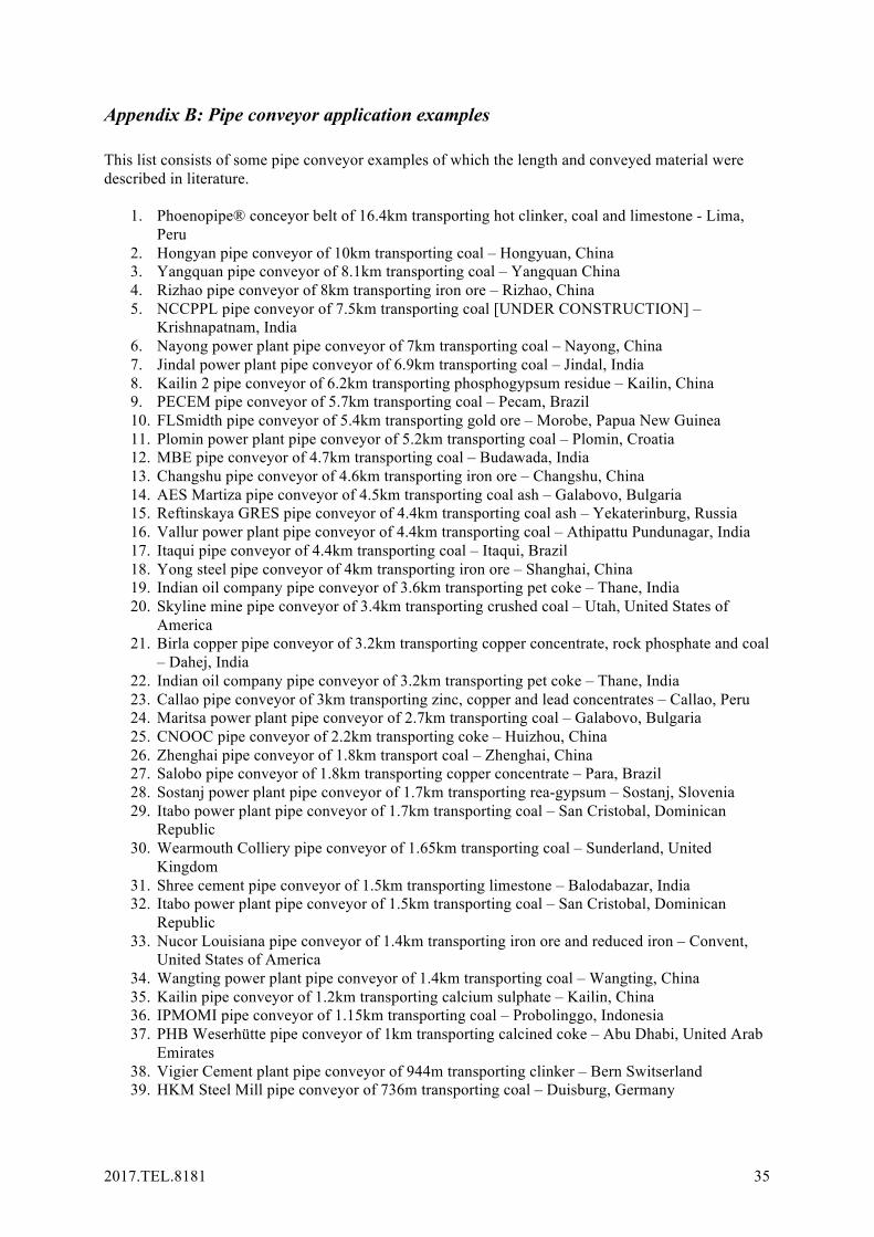
2017.TEL.8181 35
Appendix B: Pipe conveyor application examples This list consists of some pipe conveyor examples of which the length and conveyed material were described in literature.
1. Phoenopipe® conceyor belt of 16.4km transporting hot clinker, coal and limestone - Lima, Peru
2. Hongyan pipe conveyor of 10km transporting coal – Hongyuan, China 3. Yangquan pipe conveyor of 8.1km transporting coal – Yangquan China 4. Rizhao pipe conveyor of 8km transporting iron ore – Rizhao, China 5. NCCPPL pipe conveyor of 7.5km transporting coal [UNDER CONSTRUCTION] –
Krishnapatnam, India 6. Nayong power plant pipe conveyor of 7km transporting coal – Nayong, China 7. Jindal power plant pipe conveyor of 6.9km transporting coal – Jindal, India 8. Kailin 2 pipe conveyor of 6.2km transporting phosphogypsum residue – Kailin, China 9. PECEM pipe conveyor of 5.7km transporting coal – Pecam, Brazil 10. FLSmidth pipe conveyor of 5.4km transporting gold ore – Morobe, Papua New Guinea 11. Plomin power plant pipe conveyor of 5.2km transporting coal – Plomin, Croatia 12. MBE pipe conveyor of 4.7km transporting coal – Budawada, India 13. Changshu pipe conveyor of 4.6km transporting iron ore – Changshu, China 14. AES Martiza pipe conveyor of 4.5km transporting coal ash – Galabovo, Bulgaria 15. Reftinskaya GRES pipe conveyor of 4.4km transporting coal ash – Yekaterinburg, Russia 16. Vallur power plant pipe conveyor of 4.4km transporting coal – Athipattu Pundunagar, India 17. Itaqui pipe conveyor of 4.4km transporting coal – Itaqui, Brazil 18. Yong steel pipe conveyor of 4km transporting iron ore – Shanghai, China 19. Indian oil company pipe conveyor of 3.6km transporting pet coke – Thane, India 20. Skyline mine pipe conveyor of 3.4km transporting crushed coal – Utah, United States of
America 21. Birla copper pipe conveyor of 3.2km transporting copper concentrate, rock phosphate and coal
– Dahej, India 22. Indian oil company pipe conveyor of 3.2km transporting pet coke – Thane, India 23. Callao pipe conveyor of 3km transporting zinc, copper and lead concentrates – Callao, Peru 24. Maritsa power plant pipe conveyor of 2.7km transporting coal – Galabovo, Bulgaria 25. CNOOC pipe conveyor of 2.2km transporting coke – Huizhou, China 26. Zhenghai pipe conveyor of 1.8km transport coal – Zhenghai, China 27. Salobo pipe conveyor of 1.8km transporting copper concentrate – Para, Brazil 28. Sostanj power plant pipe conveyor of 1.7km transporting rea-gypsum – Sostanj, Slovenia 29. Itabo power plant pipe conveyor of 1.7km transporting coal – San Cristobal, Dominican
Republic 30. Wearmouth Colliery pipe conveyor of 1.65km transporting coal – Sunderland, United
Kingdom 31. Shree cement pipe conveyor of 1.5km transporting limestone – Balodabazar, India 32. Itabo power plant pipe conveyor of 1.5km transporting coal – San Cristobal, Dominican
Republic 33. Nucor Louisiana pipe conveyor of 1.4km transporting iron ore and reduced iron – Convent,
United States of America 34. Wangting power plant pipe conveyor of 1.4km transporting coal – Wangting, China 35. Kailin pipe conveyor of 1.2km transporting calcium sulphate – Kailin, China 36. IPMOMI pipe conveyor of 1.15km transporting coal – Probolinggo, Indonesia 37. PHB Weserhütte pipe conveyor of 1km transporting calcined coke – Abu Dhabi, United Arab
Emirates 38. Vigier Cement plant pipe conveyor of 944m transporting clinker – Bern Switserland 39. HKM Steel Mill pipe conveyor of 736m transporting coal – Duisburg, Germany

2017.TEL.8181 36
40. Biomass pipe conveyor of 730m transporting sludge and paperpulp – Rotterdam, The Netherlands
41. SPIC fertilizer pipe conveyor of 682m transporting urea prills – Dubai, United Arab Emirates 42. Sostanj power plant pipe conveyor of 623m transporting rea-gypsum – Sostanj, Slovenia 43. Richards bay pipe conveyor of 600m transporting coal, sulphur, anthracite and phosphate rock
– Richards bay, South-Africa 44. Linz AG pipe conveyor of 475m transporting household and industrial waste and sewage
sludge – Linz, Austria 45. Nucor Decatur pipe conveyor of 380m transporting iron ore – Decatur, United States of
America 46. LKAB pipe conveyor of 341m transporting olivine and quartzite – Narvik, Norway 47. Moorburg Power Plant pipe conveyor of 260m transporting coal – Hamburg, Germany 48. Vikram Ispat pipe conveyor of 250m transporting hot briquetted iron – Mumbai, India 49. Portlandzementwerk pipe conveyor of 213m transporting clinker – Üxheim, Germany 50. Sterlite pipe conveyor of 190m transporting copper concentrate – Tuticorin, India 51. Cemij pipe conveyor of 165m transporting gypsum, clinker and anhydrate – IJmuiden, The
Netherlands 52. Neptune terminal pipe conveyor of 160m transporting potash – Vancouver, Canada 53. Coromandel Fertilisers pipe conveyor of 140m transporting ground rock phosphate –
Visakhapatnam, India 54. Vagron pipe conveyor of 139m transporting waste – Groningen, The Netherlands 55. Nyrstar pipe conveyor of 135m transporting zinc ore – Budel, The Netherlands 56. Swarttouw pipe conveyor of 120m transporting phosphate and petroleum cokes - Rotterdam,
The Netherland 57. Nyrstart pipe conveyor of 70m transporting zinc oxide – Budel, The Netherlands 58. PPG pipe conveyor of 62m transporting glass – Westerbroek, The Netherlands 59. Madras Cement pipe conveyor of 60m transporting wet fly ash and gypsum –
Thammanayakkanpatti, India


![ection (A) [75-80] - Tsubaki · Type of Conveyor Series Characteristics Temperature Range ConveyorSpecifications&Characteristics O = available X = ContactTsubakiTechnicalSupport -](https://static.fdocuments.in/doc/165x107/5e7b16da833f765b443a9763/ection-a-75-80-type-of-conveyor-series-characteristics-temperature-range-conveyorspecificationscharacteristics.jpg)


