
Overhead Wiring Layouts - Requirements and Symbology ... · RailCorp Engineering Standard —...
41
Engineering Standard Electrical Engineering Standard Overhead Wiring Layouts - Requirements and Symbology EP 08 00 00 10 SP Version 2.1 Issued April 2013 Owner: Chief Engineer, Electrical Approved by: Neal Hook Chief Engineer Electrical Authorised by: Neal Hook Chief Engineer Electrical Disclaimer This document was prepared for use on the RailCorp Network only. RailCorp makes no warranties, express or implied, that compliance with the contents of this document shall be sufficient to ensure safe systems or work or operation. It is the document user’s sole responsibility to ensure that the copy of the document it is viewing is the current version of the document as in use by RailCorp. RailCorp accepts no liability whatsoever in relation to the use of this document by any party, and RailCorp excludes any liability which arises in any manner by the use of this document. Copyright The information in this document is protected by Copyright and no part of this document may be reproduced, altered, stored or transmitted by any person without the prior consent of RailCorp. UNCONTROLLED WHEN PRINTED Page 1 of 41
Transcript of Overhead Wiring Layouts - Requirements and Symbology ... · RailCorp Engineering Standard —...
Engineering Standard Electrical
Engi
neer
ing
Stan
dard
Overhead Wiring Layouts - Requirements and Symbology
EP 08 00 00 10 SP
Version 2.1
Issued April 2013
Owner: Chief Engineer, Electrical
Approved by:
Neal Hook Chief Engineer Electrical
Authorised by:
Neal Hook Chief Engineer Electrical
Disclaimer This document was prepared for use on the RailCorp Network only. RailCorp makes no warranties, express or implied, that compliance with the contents of this document shall be sufficient to ensure safe systems or work or operation. It is the document user’s sole responsibility to ensure that the copy of the document it is viewing is the current version of the document as in use by RailCorp. RailCorp accepts no liability whatsoever in relation to the use of this document by any party, and RailCorp excludes any liability which arises in any manner by the use of this document. Copyright The information in this document is protected by Copyright and no part of this document may be reproduced, altered, stored or transmitted by any person without the prior consent of RailCorp.
UNCONTROLLED WHEN PRINTED Page 1 of 41

RailCorp Engineering Standard — Electrical EP 08 00 00 10 SP Overhead Wiring Layouts - Requirements and Symbology
© RailCorp Page 2 of 41 Issued April 2013 UNCONTROLLED WHEN PRINTED Version 2.1
Document control
Version Date Summary of change September 2008 Last Technical Review
2.0 May 2010 Application of TMA 400 format. 2.1 April 2013 Update template

RailCorp Engineering Standard — Electrical EP 08 00 00 10 SP Overhead Wiring Layouts - Requirements and Symbology
© RailCorp Page 3 of 41 Issued April 2013 UNCONTROLLED WHEN PRINTED Version 2.1
Contents
1 Introduction .............................................................................................................................5 2 References...............................................................................................................................5 2.1 Australian and International Standards.....................................................................................5 2.2 RailCorp Standards...................................................................................................................5 3 Definitions and abbreviations................................................................................................5 4 General layout requirements .................................................................................................5 4.1 Layout size and scale................................................................................................................5 4.2 Title block ..................................................................................................................................6 4.3 Format of layout details.............................................................................................................7
4.3.1 Track orientation ........................................................................................................7 4.3.2 Join lines....................................................................................................................7 4.3.3 Landmark details .......................................................................................................7
4.4 Track details..............................................................................................................................8 4.4.1 Tracks ........................................................................................................................8 4.4.2 Track geometry..........................................................................................................8 4.4.3 Track centres .............................................................................................................9
5 OHW design symbology.......................................................................................................10 5.1 Conductor details ....................................................................................................................10
5.1.1 System details for the wire run ................................................................................10 5.1.2 Bay lengths ..............................................................................................................12 5.1.3 Versine and mid-bay stagger...................................................................................13 5.1.4 Contact wires ...........................................................................................................15 5.1.5 Auxiliary feeders ......................................................................................................15 5.1.6 Pennant insulators ...................................................................................................16 5.1.7 Feeder and potential jumpers..................................................................................17
5.2 Support and registration details ..............................................................................................17 5.2.1 Cantilever arrangements .........................................................................................18 5.2.2 Overline bridge arrangements .................................................................................20 5.2.3 Tunnel arrangements...............................................................................................21
5.3 OHW support structure details................................................................................................23 5.3.1 Structure location numbers......................................................................................23 5.3.2 Masts .......................................................................................................................24 5.3.3 Portals and drop verticals ........................................................................................25 5.3.4 Wood poles..............................................................................................................27
5.4 Anchor details .........................................................................................................................27 5.4.1 Tension regulator.....................................................................................................28 5.4.2 Fixed anchor ............................................................................................................29 5.4.3 Fixed mid-point arrangement...................................................................................31 5.4.4 Guy arrangements ...................................................................................................32 5.4.5 OHW termination insulators.....................................................................................33
5.5 Overlap details ........................................................................................................................34 5.5.1 Jumpered / switched open overlaps ........................................................................35 5.5.2 Non-sectionable overlaps ........................................................................................36

RailCorp Engineering Standard — Electrical EP 08 00 00 10 SP Overhead Wiring Layouts - Requirements and Symbology
© RailCorp Page 4 of 41 Issued April 2013 UNCONTROLLED WHEN PRINTED Version 2.1
5.5.3 Feeding open overlaps ............................................................................................36 5.6 Section insulator (S.I.) details .................................................................................................37 5.7 Switch arrangement details.....................................................................................................38 5.8 Feeding arrangement details ..................................................................................................39 5.9 Surge arrester details..............................................................................................................40 5.10 Over-run protection details......................................................................................................40 5.11 Sign details..............................................................................................................................40 5.12 Bonding details........................................................................................................................41 5.13 Other details............................................................................................................................41

RailCorp Engineering Standard — Electrical EP 08 00 00 10 SP Overhead Wiring Layouts - Requirements and Symbology
© RailCorp Page 5 of 41 Issued April 2013 UNCONTROLLED WHEN PRINTED Version 2.1
1 Introduction This document sets out the requirements for overhead wiring layouts prepared for RailCorp. It also describes the standard symbols and approach to be used to show 1500 V dc Overhead Wiring design details on the layouts.
The requirements of this document shall be used for the development of all future OHW layouts and major modifications to existing OHW layouts.
2 References
2.1 Australian and International Standards AS 1100 Part 101:1992 “Technical drawing - General principles
2.2 RailCorp Standards ED 0024P – “CAD and Drafting Manual – Electrical” ED 0026P – “CAD and Drafting Manual – Track”
3 Definitions and abbreviations OHW Overhead Wiring
Standard cell Standard representation (including size, etc.) of an item, either by CAD or by other manual means.
Symbology Describes the type of information to be shown on the layout and the way this information is to be placed on the layout.
Tension length A tension length is the length of regulated wire from moving to fixed anchors.
TX Text size
Wire run For regulated OHW, a length of wire generally from moving anchor to fixed mid-point to moving anchor, or from moving anchor to fixed anchor. For fixed anchored wire, the length of wire from anchor to anchor.
WT Text or line weight
4 General layout requirements Layouts shall be produced in CAD. The preferred file format is MicroStation, version 8.
4.1 Layout size and scale OHW layouts shall be produced in “A1” size, grid coordinated and to a scale of 1:500.
Borders to AS 1100 Part 101 (1992).

RailCorp Engineering Standard — Electrical EP 08 00 00 10 SP Overhead Wiring Layouts - Requirements and Symbology
© RailCorp Page 6 of 41 Issued April 2013 UNCONTROLLED WHEN PRINTED Version 2.1
4.2 Title block Refer to ED 0024P – “CAD and Drafting Manual – Electrical”.
The standard title block extends along the length of the bottom of the drawing sheet.
The drawing number shall be in accordance with current RailCorp drawing number document (EDMS Drawing Registration Number).
(a) Revision no.
Heading for the Amendments column.
(b) Amendments column
A brief description of the various amendments to the layout shall be placed in the “Amendments Column”, which is located at the bottom left-hand corner of the layout sheet. Amendments begin as “A. Original Issue.”, and begin after the drawing has been approved.
The description of the changes shall be sufficiently clear so as to provide a trace into the history of the drawing.
(c) CAD reference files and models
List the various reference and model files that make up the final OHW layout. This would typically include the OHW model file, the track model, mapping model, grid file, etc.
(d) Scales
This will show “1 : 500”. “CAD Drawing” is shown in lower box to indicate that the drawing is done in CAD and future updates are to be done in CAD.
(e) Reference drawings
List of various reference drawings pertaining to the OHW design, such as cantilever standard arrangements, OHW spacing chart, cross-section drawings, etc. Note that this space is for drawing numbers, not CAD reference files.
(f) Space for Design Organisation
Space for the company designing the OHW layouts to place their logo, the following headings and the accompanying signatures:
– Drawn – the person responsible for making up the OHW layout as a drawing. – Drawing Check – the person responsible for checking compliance with various
CAD requirements, including the requirements of this document. – Designed – the person responsible for performing the OHW design work for this
layout. – Design Check – the person responsible for checking/verifying the OHW design. – Approved – the Design Organisation’s representative who is ultimately
responsible for the delivery of the design, confirming that it meets the appropriate specification.
(g) Drawing title block
See ED 0024P – “CAD and Drafting Manual – Electrical”.

RailCorp Engineering Standard — Electrical EP 08 00 00 10 SP Overhead Wiring Layouts - Requirements and Symbology
4.3 Format of layout details OHW layouts show the details that are necessary to describe how the OHW is to be installed and also its as-built configuration for later reference.
4.3.1 Track orientation Track details on the layout shall be placed traversing from left to right across the layout.
The Sydney end of the trackwork is on the left side of the layout, and the country end is on the right side.
4.3.2 Join lines Dashed join lines are used to show where the details of the trackwork end on the layout. The details are continued on the adjoining layouts. The join lines on adjacent layouts shall perfectly coincide so that the layouts can be aligned at the join line to show the correct (extended) track details. The adjacent layout shall be referred to by the following text placed at the join line, “Adjoining Layout - ” then the drawing number of the adjoining layout.
The dashed lines are usually applied perpendicular to the tracks.
Standard cells
Join lines:
Line style = Long Dash – Short Dash – Long Dash
Text for reference to adjacent layout:
TX = 3.5 mm, WT = 0.35 mm
4.3.3 Landmark details Layouts shall show landmark details such as the location of substations / sectioning huts, stations, level crossings, other service crossings, adjacent streets, houses, underline bridges, culverts, HV aerial lines, etc. within approximately 100 m from the track.
The details of this supplementary information are provided to give a better feel of the surrounding area, particularly with obstructions in mind (for design and construction) and for locating OHW with respect to these landmarks, especially for street names (for reference by maintenance workers).
It is important to note that not all “landmark” information is controlled, eg. any changes to the streets, etc. will not necessarily be reflected in the layouts. Therefore this information shall only be sufficient to show the likely design/construction problems and to locate a few landmarks for the purposes of locating adjacent OHW.
Nearby street names shall be placed on the layout for ready reference both during construction and for later maintenance activities.
© RailCorp Page 7 of 41 Issued April 2013 UNCONTROLLED WHEN PRINTED Version 2.1

RailCorp Engineering Standard — Electrical EP 08 00 00 10 SP Overhead Wiring Layouts - Requirements and Symbology
© RailCorp Page 8 of 41 Issued April 2013 UNCONTROLLED WHEN PRINTED Version 2.1
Standard cells
Landmark details shall be shown with a light, dashed linework, using the following:
Line style = dotted
WT = 0.25 mm
Street names:
TX = 3.5 mm, WT = 0.35 mm, Line style = Solid.
4.4 Track details Various track-related details are needed in order to properly design the OHW. The symbology for showing track details is shown below.
4.4.1 Tracks The rails of a track shall be shown as two parallel solid lines separated by 1,435 mm (appropriately scaled) with no centre line.
The name of the track shall be shown between the rails of each track at appropriate distances along the track to aid identification.
Standard cells
Track Rails:
Line style = Solid
WT = 0.25 mm
Track Name:
TX = 1.8 mm
WT = 0.25 mm
4.4.2 Track geometry The following track details shall be indicated on the layouts:
• TP (tangent point) - defines where a straight section of track joins a curve. • TRS (transition) - defines the junction between a transition and the start of a
circular curve. • CTP (compound tangent point) - defines the junction between one circular curve
to another. • Track radius - on constant curves the track radius (in metres) shall be shown
between the rails of a particular track.
Refer to ED 0026P – “CAD and Drafting Manual – Track”

RailCorp Engineering Standard — Electrical EP 08 00 00 10 SP Overhead Wiring Layouts - Requirements and Symbology
Standard cells
TP (tangent point)
CTP (compound tangent point)
WT = 0.18 mm
TRS (transition)
WT = 0.18 mm
Track radius
Worded in the format “R.” then the radius. Applied between the rails of a track.
TX = 1.8 mm
WT = 0.25 mm
e.g. R. 800 (800 m radius curve)
4.4.3 Track centres Where appropriate, the distance between adjacent tracks shall be placed between these tracks. Where the track centres vary, then show as “VAR CNTRS”.
© RailCorp Page 9 of 41 Issued April 2013 UNCONTROLLED WHEN PRINTED Version 2.1

RailCorp Engineering Standard — Electrical EP 08 00 00 10 SP Overhead Wiring Layouts - Requirements and Symbology
© RailCorp Page 10 of 41 Issued April 2013 UNCONTROLLED WHEN PRINTED Version 2.1
Standard cells
TX = 2.5 mm
WT = 0.25 mm
5 OHW design symbology This section identifies the various types of OHW equipment and the requirements for showing the relevant design details on layout plans.
5.1 Conductor details OHW conductors include the following hardware:
• catenary (including auxiliary feeder), • contact, • droppers (catenary to contact), • in-span feeders, • knuckles (including steel, insulated and sliding knuckles), • contact splices, • catenary splices, • pennant insulators, • feeder and potential jumpers, • contact wear strips.
The details of some of these items of equipment shall be shown on the layouts, as described below.
5.1.1 System details for the wire run Symbology
Each overhead wire run shall be defined with the details of the run, including the cantilever series drawing number used for support and registration, details of the catenary and contact wires, and the name of the wire run.
The details of the wire run shall be shown at the Sydney-end anchor location for the run, as shown below.
The tension length (rounded to nearest metre), the wire run name and the track designation shall be shown at both the Sydney-end and country-end anchors for the wire run. The tension length shall be shown, followed by a lower case “m” symbol (metres).
With this approach, maintenance staff wishing to know the details of the OHW conductors simply trace the wire run back to the Sydney-end anchor location for that information.
The wire information shall be located adjacent to the standard symbol for the anchor (“M” or “F”) and shall take the following form (Refer to Section 5.4 Anchor details):
• Tension length (m) (this information shall be located above the arrow in the anchor symbol)
• “Track = ” Track description (OHW wired for this track) • “Name = ” Unique identifier of the wire run.

RailCorp Engineering Standard — Electrical EP 08 00 00 10 SP Overhead Wiring Layouts - Requirements and Symbology
The wire run name shall consist of eight characters with the following format: The wire run name shall consist of eight characters with the following format:
LLDTKKKX LLDTKKKX Where Where
LL is a two letter electrical line prefix. Where the line prefix has only one character, it is right-padded with a dash, eg “SW”, “N-”. LL is a two letter electrical line prefix. Where the line prefix has only one character, it is right-padded with a dash, eg “SW”, “N-”.
D is a single letter track direction code (“D” - Down, “U” - Up, “-” Single line). D is a single letter track direction code (“D” - Down, “U” - Up, “-” Single line).
T is a single letter code for the track name (“M” – Main, “S” – Suburban, “L” – Local, “R” – Refuge or Relief, “X” – Crossover, “Z” – Sidings and others). T is a single letter code for the track name (“M” – Main, “S” – Suburban, “L” – Local, “R” – Refuge or Relief, “X” – Crossover, “Z” – Sidings and others).
KKK consists of three numeric characters indicating the electrical kilometrage of the first structure in the wire run, rounded down to the nearest kilometre. For example, if the structure location is 2+987, then KKK is 002.
KKK consists of three numeric characters indicating the electrical kilometrage of the first structure in the wire run, rounded down to the nearest kilometre. For example, if the structure location is 2+987, then KKK is 002.
X is a single letter used to help distinguish different runs starting at the same kilometrage (“A”, “B”, “C”, etc.) X is a single letter used to help distinguish different runs starting at the same kilometrage (“A”, “B”, “C”, etc.)
For example, “SWDM060B” is the name of the wire run for the Down Illawarra starting at structure SW60+367, and is the second wire run for the Down Illawarra that starts at that kilometrage.
For example, “SWDM060B” is the name of the wire run for the Down Illawarra starting at structure SW60+367, and is the second wire run for the Down Illawarra that starts at that kilometrage.
For the Sydney-end anchor location only, the following additionalFor the Sydney-end anchor location only, the following additional information is required (for the sake of brevity, there is no need to show units):
• “Cantilevers = ” Drawing number for cantilever standard arrangement • “Caty = ” Size (sq mm) / Tension (kN) / Standard Height (m) • “Cont = ” Size (sq mm) / Tension (kN) / Standard Height (m) • “(HD Cu)” or “(Sn Cu)” to indicate the type of contact wire (hard drawn copper or tin
bearing copper respectively)
Where twin conductors are used, prefix the size and tension with “2x” as in the example below.
Example:
The Sydney-end anchor details would typically be:
532 m
Track = UP LOCAL Name = MSUL003A Cantilevers = A1/89232 Caty = 270 / 30.0 / 6.5 Cont = 2x137 / 2x12.5 / 5.0 (HD Cu)
The corresponding country-end anchor details would typically be:
532 m
Track = UP LOCAL Name = MSUL003A
The standard catenary and contact heights may be altered from those shown on the cantilever standard arrangements for the specific wire run. This is achieved by describing the new standard height under the catenary and contact definitions, e.g. Caty = 270 / 30.0 / 6.75 states that the standard catenary height to be used throughout
© RailCorp Page 11 of 41 Issued April 2013 UNCONTROLLED WHEN PRINTED Version 2.1

RailCorp Engineering Standard — Electrical EP 08 00 00 10 SP Overhead Wiring Layouts - Requirements and Symbology
this particular run is 6.75 m. Cantilevers with non-standard heights can be individually specified by employing a “∗” symbol in the cantilever coding, as detailed in Section 5.2.1
Cantilever arrangements.
Standard cells
Sheet 1 OHW System Details:
TX = 3.5 mm, WT = 0.35 mm
Anchor Details:
Refer to Section 5.4 Anchor details for format requirements relating to the specific type of anchor.
Formatted as per the below example.
Example:
Note that certain anchor details are also shown adjacent to the above anchor symbols - refer to Section 5.4 Anchor details for more information.
5.1.2 Bay lengths Symbology
Bay lengths are shown on the layout as a reference when designing and constructing OHW, and later on when maintaining this infrastructure.
The individual conductor bay lengths shall be shown to the nearest metre and shall be located on the layout approximately mid-way between corresponding OHW support locations.
Where common structures support the OHW for two or more tracks, the bay length only needs to be shown once. The exception occurs on curved track - if the bay lengths differ by 1 m or more then they shall be identified for track pairs, e.g. bay length for Up and Down Mains may be labelled as 45 m whereas for the Up and Down Subs it may be 46 m.
Bay lengths shall be located adjacent to the relevant tracks.
© RailCorp Page 12 of 41 Issued April 2013 UNCONTROLLED WHEN PRINTED Version 2.1

RailCorp Engineering Standard — Electrical EP 08 00 00 10 SP Overhead Wiring Layouts - Requirements and Symbology
Bays of wire coming from or going to anchor shall have the letter “A” added to the bay length (“A” for Anchor) and appear next to the conductor. This is done to enhance understanding of where the conductors are going. Example: “46A” is a 46 m bay going to Anchor. Where this bay length appears next to the in-running bay length, they shall be separated by a “/”, e.g. 48 / 46A.
In some cases the actual bay length may differ from the simple subtraction of structure location numbers. Here the bay lengths shall have a space and the letters “ACT” appended to the bay length. Example: “45 ACT” means the actual bay length is 45 m, as measured in the field.
Bay lengths shall be shown on the layout as rounded to the nearest metre, unless these lengths are deemed by the designer to be so critical as to require specifying to the nearest 0.5 m.
Standard cells
Bay Length:
TX = 3.5 mm
WT = 0.35 mm
5.1.3 Versine and mid-bay stagger Symbology
For each bay of in-running OHW conductors there shall be a table nominating the track and showing the design track versine and the design mid-bay stagger (both in mm). This is important information that must be documented - it is intended to help confirm pantograph security for the bay.
The table shall appear about midway between associated support structures and generally away from the tracks (to reduce congestion).
An up or down arrow shall be used in the table to indicate the direction of the mid-bay stagger (with respect to track superelevated centre-line).
Example:
VS MBS DM 345 83 ↑ UM 345 45 ↓
where
“DM” = abbreviation for Down Main track
“UM” = abbreviation for Up Main track
“VS” = Versine (mm)
“MBS” = Mid-bay Stagger (mm)
Note that this information is not required for bays of wire that are fully out-of-running or going to anchor.
In overlaps where two sets of wires exist for a bay, the tables shall be set up to provide two sets of mid-bay stagger (MBS) values but only one versine (VS) value for each track. (See Standard cells below).
© RailCorp Page 13 of 41 Issued April 2013 UNCONTROLLED WHEN PRINTED Version 2.1

RailCorp Engineering Standard — Electrical EP 08 00 00 10 SP Overhead Wiring Layouts - Requirements and Symbology
Where a common bay length exists for multiple tracks, a multiple entry table can be used (e.g. for four tracks, use table with four rows plus heading). Conversely, if bay lengths differ from track to track, then use the single entry tables.
Versine
A standard symbol that indicates the direction of net track curvature is normally positioned directly above the “VS” column in the standard Versine/MBS table. This symbol is particularly needed where it is not immediately obvious which direction the curvature takes, e.g. on tracks with large radius (almost tangent track).
Normal Bays
This format is used where there is only one wire in a bay (so it is not used in an overlap – refer to “Overlap Situations” below). Additional rows can be added to build a larger table where more than one track exists which all have the same bay length.
Overlap Situations
This format is used for describing the situation where two wires exist within the bay. The track has one versine, but there are two mid-bay stagger figures to enter. Additional rows can be added to build a larger table where more than one track exists.
Standard cells
Tables:
TX = 2.5 mm, WT = 0.25 mm
Box dimensions:
Versine
Curve to be crescent shaped and approximately 8 mm from end to end (refer to above example).
WT = 0.25 mm
© RailCorp Page 14 of 41 Issued April 2013 UNCONTROLLED WHEN PRINTED Version 2.1

RailCorp Engineering Standard — Electrical EP 08 00 00 10 SP Overhead Wiring Layouts - Requirements and Symbology
© RailCorp Page 15 of 41 Issued April 2013 UNCONTROLLED WHEN PRINTED Version 2.1
5.1.4 Contact wires Symbology
In-running and out-of-running contact wires shall be shown in areas where it is uncertain where the wires are in relation to each other, such as in the following cases:
• Overlaps, • Crossovers, • Turnouts, • Sidings, • Overline bridges, • Congested areas with multiple wires (to be able to trace wires through).
Where required, they shall be drawn accurately so that the relative positioning of the wires is obvious (for construction).
In-running contact wires shall be shown as solid lines.
Out-of-running contact wires and pennants shall be shown as dashed lines on the layout.
For the case of twin contacts, only show a single line, representing the “mean” contact position (as in single contact situation).
Standard cells
In-running contact wires:
Line style = Solid line
Out-of-running contact wires:
Line style = Medium dash
Line thickness:
WT = 0.35 mm
5.1.5 Auxiliary feeders Symbology
Auxiliary feeders run in parallel with the OHW to upgrade its current carrying capability.
Instances of auxiliary feeders shall be shown on the layout using the standard symbol (below), with an arrow to the auxiliary feeder.
The auxiliary feeder shall be shown as a long dash – short dash line that can be traced from anchor to anchor if deemed appropriate.
Sufficient information shall be shown on the layout to enable the auxiliary feeder to be constructed. This would typically require a reference to a standard support/registration arrangement drawing or specific cross-section drawing for each support location (such as an Auxiliary Feeder Design Schedule).

RailCorp Engineering Standard — Electrical EP 08 00 00 10 SP Overhead Wiring Layouts - Requirements and Symbology
Standard cells
Box:
Size = 15 mm x 5 mm
WT = 0.25 mm
Text:
TX = 3.5 mm
WT = 0.35 mm
Auxiliary feeder line work:
Line style = Long Dash – Short Dash
WT = 0.35 mm
5.1.6 Pennant insulators Symbology
Instances of pennant insulators required for the sectioning of out-of-running OHW shall be shown on the layout as a single filled circle on the line drawn to represent the OHW conductors. Termination insulators (see Section 5.4.5) are shown as a pair of such symbols.
Example:
Standard cells
Overall diameter = 1.25 mm, Solid Dot
© RailCorp Page 16 of 41 Issued April 2013 UNCONTROLLED WHEN PRINTED Version 2.1

RailCorp Engineering Standard — Electrical EP 08 00 00 10 SP Overhead Wiring Layouts - Requirements and Symbology
5.1.7 Feeder and potential jumpers Symbology
The designer shall show on the layout all instances of feeder jumpers and potential jumpers, e.g. at crossovers, overlaps, etc.
The jumpers shall be shown as an arc (curved line) bridging between the two sets of conductors.
Feeder jumpers shall be identified on the layout as “FJ” with an arrow to the jumper. Likewise, potential jumpers shall be identified as “PJ” with an arrow to the jumper.
The standard jumper arrangement to be used shall be identified in the “Reference Drawings” section of the layout drawing, e.g. Feeder Jumpers – EL0004637; Potential Jumpers – EL0006416.
Example:
Contact wires shown crossing, with feeder jumper symbol (tracks omitted for clarity).
Standard cells
Feeder or potential jumper:
An arc of suitable dimensions with the same symbology (attributes) as contact wire.
Text:
“FJ” Standard “Feeder Jumper” symbol, with
TX = 3.5 mm, Line style = Solid, WT = 0.35 mm.
“PJ” Standard “Potential Jumper” symbol, with
TX = 3.5 mm, Line style = Solid, WT = 0.35 mm.
5.2 Support and registration details A range of OHW support and registration arrangements exist for the various types of situations encountered, including cantilevers, portal suspensions, pull-offs, polygons, overline bridges and tunnels. The requirements for each are listed below.
The applicable overhead wiring structure spacing chart drawing is to be included in the “Reference Drawing” section of the Title Block. See Section 4.2.
© RailCorp Page 17 of 41 Issued April 2013 UNCONTROLLED WHEN PRINTED Version 2.1

RailCorp Engineering Standard — Electrical EP 08 00 00 10 SP Overhead Wiring Layouts - Requirements and Symbology
5.2.1 Cantilever arrangements Cantilever Standard Arrangements
The drawing number for the cantilever standard arrangement series shall be shown at the Sydney-end anchor for the wire run – refer to Section 5.1.1 for the format of this information.
Cross-sections
The “See Cross-section” symbol is used at a particular structure location to notify that a cross-section has been drawn for that location.
Cross-sections must be drawn where the cantilever coding cannot adequately describe the details of the support/registration arrangements at that location.
Wherever possible, the cross-section symbol shall appear next to and in line with the OHW support structure location number.
An “I” symbol inside a circle, located in the cantilever secondary coding, is used to define the cantilever that requires reference to the drawn up cross-section.
Primary Cantilever Coding
Individual cantilevers are shown on the layout as a cantilever code located inside an oval symbol. This oval symbol shall allow for up to 10 characters for the coding.
Wherever practical and appropriate, all cantilever coding shall appear lining up with the relative OHW structure location for easy identification. In the case of cantilevers appearing on twin drop verticals, the oval symbols shall be shown side by side and staggered, with the code for the Sydney-end and country-end cantilevers in the corresponding position. This is done to help understand the relative locations of the cantilevers.
Where required for clarity, the track description shall appear adjacent to the oval symbol to help describe the location of the cantilever and conductors, e.g. “UP MN” (Up Main track) in the example below. Where symbols for more than one wire run appear on the same side of the track, then the track description shall be shown.
Example:
Further descriptions may be necessary to describe the particular OHW conductor that the coding is intended for, e.g. “OOR” (Out-of-Running conductor) or “I/R” (In-Running conductor).
Example:
For two track situations, it is desirable to locate one code on each side of the corridor.
© RailCorp Page 18 of 41 Issued April 2013 UNCONTROLLED WHEN PRINTED Version 2.1
RailCorp Engineering Standard — Electrical EP 08 00 00 10 SP Overhead Wiring Layouts - Requirements and Symbology
For four track situations, it is preferable to locate two codes on each side of the corridor, as appropriate.
For six track situations, preferably place the coding with four codes on the down side (top half of layout) and the remaining two codes on the up side (lower half of the layout). This approach spaces the coding out evenly, allowing for the structure location number to appear on the lower half of the page. Alternatively, place three codes on each side.
Secondary Cantilever Coding
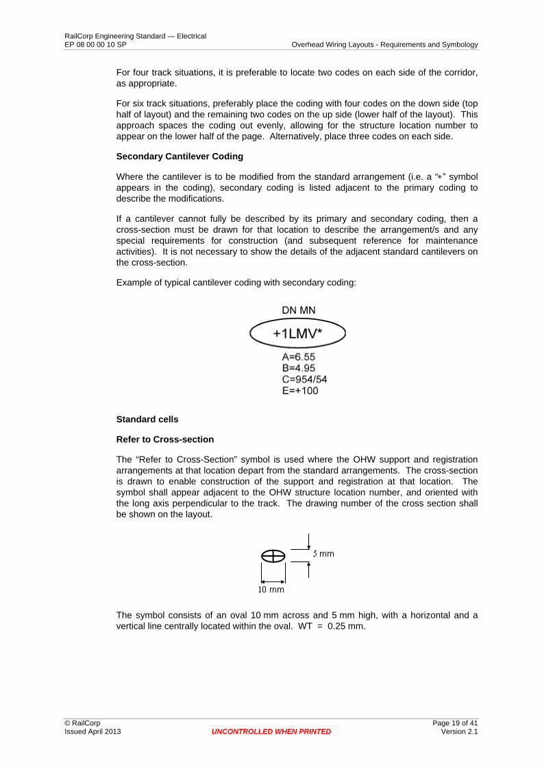
Where the cantilever is to be modified from the standard arrangement (i.e. a “∗” symbol appears in the coding), secondary coding is listed adjacent to the primary coding to describe the modifications.
If a cantilever cannot fully be described by its primary and secondary coding, then a cross-section must be drawn for that location to describe the arrangement/s and any special requirements for construction (and subsequent reference for maintenance activities). It is not necessary to show the details of the adjacent standard cantilevers on the cross-section.
Example of typical cantilever coding with secondary coding:
Standard cells
Refer to Cross-section
The “Refer to Cross-Section” symbol is used where the OHW support and registration arrangements at that location depart from the standard arrangements. The cross-section is drawn to enable construction of the support and registration at that location. The symbol shall appear adjacent to the OHW structure location number, and oriented with the long axis perpendicular to the track. The drawing number of the cross section shall be shown on the layout.
The symbol consists of an oval 10 mm across and 5 mm high, with a horizontal and a vertical line centrally located within the oval. WT = 0.25 mm.
© RailCorp Page 19 of 41 Issued April 2013 UNCONTROLLED WHEN PRINTED Version 2.1

RailCorp Engineering Standard — Electrical EP 08 00 00 10 SP Overhead Wiring Layouts - Requirements and Symbology
Primary Cantilever Coding:
The Cantilever Coding symbol is an oval of size 30 mm by 10 mm, with:
Line style = Solid, WT = 0.25 mm.
Up to 10 characters (representing the cantilever coding) can appear within the oval symbol. Characters have:
TX = 3.5 mm, WT = 0.35 mm.
Secondary Cantilever Coding:
Text describing the secondary cantilever coding shall have the attributes:
TX = 2.5 mm, WT = 0.25 mm.
Track Description
TX = 2.5 mm, WT = 0.25 mm.
5.2.2 Overline bridge arrangements Symbology
Arrangement
Overline bridge (OLB) arrangements describe the method of supporting and registering the OHW to the bridge. The arrangement is shown on a separate drawing, which is referenced on the layout. This reference drawing also includes any necessary bonding arrangements, safety screens, insulated stop beams, etc. Items shown on the bridge drawing are not shown individually on the layout.
Such drawings are not needed if the OHW passes under the bridge unattached.
The name of the OLB shall be shown on the layout at or near the bridge, along with its track kilometrage from Central.
The OLB arrangement drawing shall be referenced on the layout at a suitable location adjacent to the bridge.
The layout shall show all locations where the OHW conductors are supported and/or registered under the bridge, using the same symbology as for the “Tunnel” situation (described in the next section).
OHW / bridge profile
The profile of the OHW is normally drawn approaching and leaving the bridge.
The profile starts, ends and includes any location that has non-standard catenary and/or contact heights. This typically occurs near bridges because existing bridges generally have less than standard vertical clearance.
© RailCorp Page 20 of 41 Issued April 2013 UNCONTROLLED WHEN PRINTED Version 2.1

RailCorp Engineering Standard — Electrical EP 08 00 00 10 SP Overhead Wiring Layouts - Requirements and Symbology
© RailCorp Page 21 of 41 Issued April 2013 UNCONTROLLED WHEN PRINTED Version 2.1
The production of a profile is evidence that the designer has fully investigated any reduced clearance issues around the bridge.
The profile also gives construction staff useful information about the catenary and contact heights adjacent to the bridge, especially in terms of being able to generate non-standard dropper lengths.
Bridge profiles shall be shown on a separate drawing and referenced on the layout adjacent to the bridge. Alternatively, they can be included on the layout provided sufficient space exists without creating congestion. In this case the profile shall be appropriately labelled with bridge name, structure locations, bay lengths, track grade, catenary and contact heights, bridge heights and any other information that is deemed necessary to convey the total picture to construction and maintenance staff.
Profiles are to be shown with an enlarged vertical scale, typically 1:50 vertical (and 1:500 horizontally).
If tracks are significantly different in levels, then separate profiles shall be drawn.
Standard cells
Lettering size for name of bridge:
TX = 3.5 mm, WT = 0.35 mm
Lettering size for drawing reference:
TX = 3.5 mm, WT = 0.35 mm
Standard symbol for OHW attached to OLB:
Utilise same symbology as for showing “Tunnel” arrangements (refer to next Section 5.2.3 Tunnel arrangements).
5.2.3 Tunnel arrangements Symbology
As with overline bridges, tunnels place special requirements on the way OHW is supported and registered, usually because of the limited space available for attachment of OHW fittings.
Where standard cantilever arrangements are employed in tunnels (e.g. supported from drop verticals) the coding shall be clearly shown adjacent to the Structure Location Number as for the open track situation.
Where the OHW is supported using special arrangements, these must be identified on the layout in a manner that clearly establishes what is to be constructed at each support/registration location. This would be typically done by referring to various standard arrangement drawings or by issuing a cross-section for each location (with a “See Cross-Section” symbol next to location number), or by referring to a tunnel arrangement drawing.
A Tunnel Profile is required anywhere the contact wire is below standard height, such as within the tunnel (including the area leading up to and exiting the tunnel). The profile would generally be shown on a separate drawing for the length of the tunnel, with similar requirements as for bridges (refer to previous section, “OHW/bridge profile”).
RailCorp Engineering Standard — Electrical EP 08 00 00 10 SP Overhead Wiring Layouts - Requirements and Symbology
Standard cells
Lettering size for drawing reference:
TX = 3.5 mm, WT = 0.35 mm
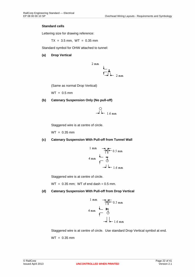
Standard symbol for OHW attached to tunnel:
(a) Drop Vertical
(Same as normal Drop Vertical)
WT = 0.5 mm
(b) Catenary Suspension Only (No pull-off)
Staggered wire is at centre of circle.
WT = 0.35 mm
(c) Catenary Suspension With Pull-off from Tunnel Wall
Staggered wire is at centre of circle.
WT = 0.35 mm; WT of end dash = 0.5 mm.
(d) Catenary Suspension With Pull-off from Drop Vertical
Staggered wire is at centre of circle. Use standard Drop Vertical symbol at end.
WT = 0.35 mm
© RailCorp Page 22 of 41 Issued April 2013 UNCONTROLLED WHEN PRINTED Version 2.1

RailCorp Engineering Standard — Electrical EP 08 00 00 10 SP Overhead Wiring Layouts - Requirements and Symbology
Example:
Track with three suspension locations and pull-offs alternating. First location has pull-off from Drop Vertical. Others have pull-off from special wall bracket.
5.3 OHW support structure details The following typical OHW support structures are available:
(a) Masts (See Section 5.3.2
Masts)
Includes:
– free standing mast with cantilever attached on one side or cantilevers back-to-back.
– anchor mast with ground guy.
(b) Portals with drop verticals (Refer to Section 5.3.3 Portals and drop verticals)
Includes:
– two, four, six track portals, etc. of appropriate size. – Cantilever and nose arrangement. – Portal booms used in cuttings. – Various styles of Drop Verticals, eg. “DS”, “DR”, “DT”, “DTA”, etc.
(c) Wood Poles (Refer to Section 5.3.4 Wood poles)
5.3.1 Structure location numbers Symbology
Each OHW support structure shall be given a unique location number which represents the approximate distance from Sydney (Central Station) in kilometres.
The next structure location (away from Sydney) is the previous location number plus the bay length (chord where there is a curved track) in metres, measured on the down rail of the down track.
The format of the OHW structure location number is:
The above OHW structure location is on the Sydney to Lithgow line (“SL”), at a point approximately 14.437km from Central.
© RailCorp Page 23 of 41 Issued April 2013 UNCONTROLLED WHEN PRINTED Version 2.1
RailCorp Engineering Standard — Electrical EP 08 00 00 10 SP Overhead Wiring Layouts - Requirements and Symbology
Line prefixes are standard one or two character prefixes representing the general rail corridor. The “+” sign is used to avoid confusion with actual track kilometres (which use a decimal point as a separator).
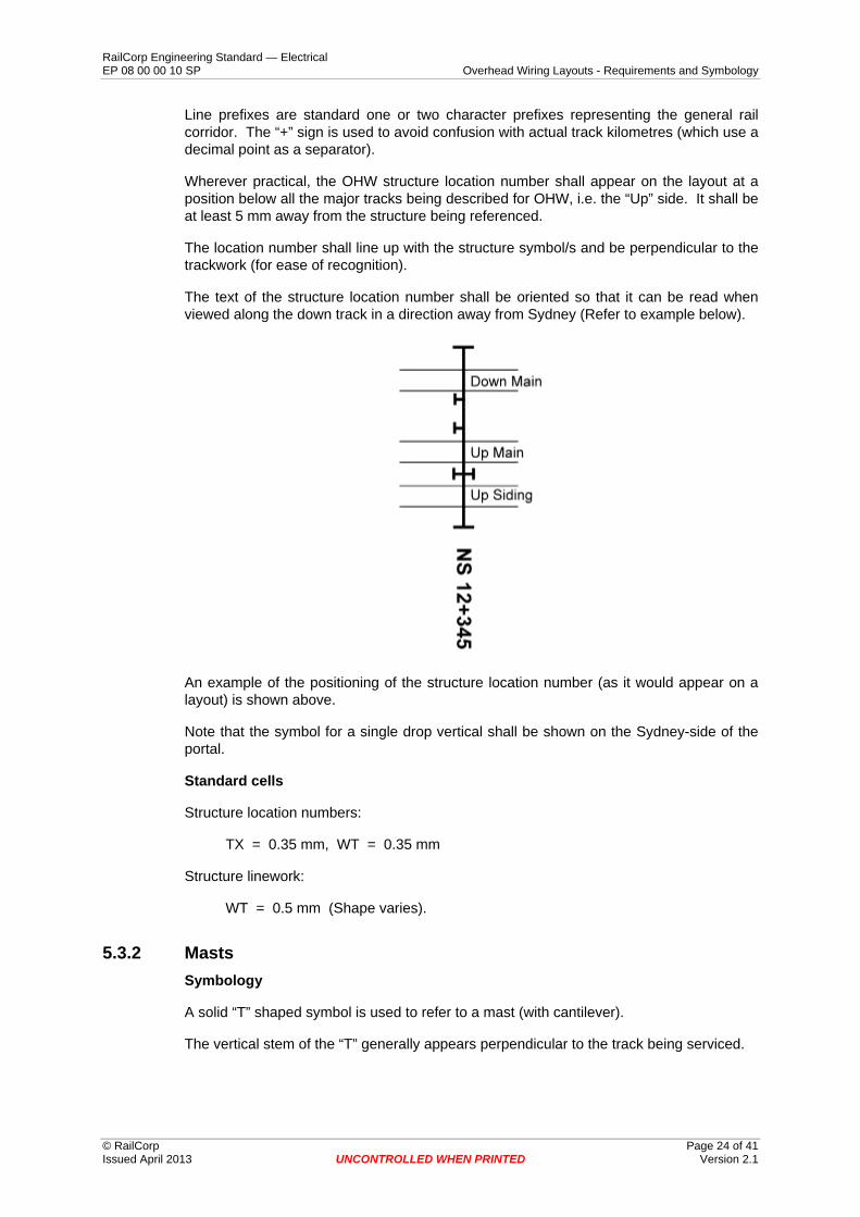
Wherever practical, the OHW structure location number shall appear on the layout at a position below all the major tracks being described for OHW, i.e. the “Up” side. It shall be at least 5 mm away from the structure being referenced.
The location number shall line up with the structure symbol/s and be perpendicular to the trackwork (for ease of recognition).
The text of the structure location number shall be oriented so that it can be read when viewed along the down track in a direction away from Sydney (Refer to example below).
An example of the positioning of the structure location number (as it would appear on a layout) is shown above.
Note that the symbol for a single drop vertical shall be shown on the Sydney-side of the portal.
Standard cells
Structure location numbers:
TX = 0.35 mm, WT = 0.35 mm
Structure linework:
WT = 0.5 mm (Shape varies).
5.3.2 Masts Symbology
A solid “T” shaped symbol is used to refer to a mast (with cantilever).
The vertical stem of the “T” generally appears perpendicular to the track being serviced.
© RailCorp Page 24 of 41 Issued April 2013 UNCONTROLLED WHEN PRINTED Version 2.1

RailCorp Engineering Standard — Electrical EP 08 00 00 10 SP Overhead Wiring Layouts - Requirements and Symbology
The location of the “T” shall accurately reflect the location of the centre of the mast on the layout, and is typically 3.2 m from the track being serviced or the closest track. So, location of the centre of the mast in terms of Eastings & Northings can be determined from this symbol.
Standard cells
Structure linework:
WT = 0.5 mm.
Cantilever Mast
Marks the location of where a standard mast with cantilever is to be located. The long stem indicates the cantilever frame (plan view) while the perpendicular stroke at the end represents the centre-line of the mast. These cells are normally located with the centre of mast 3.2 m from the track centre-line, and oriented perpendicular to the track.
Pull-off Mast
Marks the location of where a standard mast with pull-off is to be located. The dashed line represents the pull-off span (plan view) while the perpendicular stroke at the end is the centre-line of the mast. These cells are normally located with the mast 3.2 m from the track centre-line, and oriented perpendicular to the track.
Anchor Mast
Symbol indicates U.C. anchor mast only, i.e. No supporting cantilever or pull-off.
Orientation of symbol shall dictate orientation in field.
5.3.3 Portals and drop verticals Symbology
Portals
A portal is represented on the layout as a long solid line spanning all tracks being serviced, and has a short perpendicular stroke at each end (which represent the legs of the portal). The line is generally perpendicular to the tracks being serviced.
© RailCorp Page 25 of 41 Issued April 2013 UNCONTROLLED WHEN PRINTED Version 2.1

RailCorp Engineering Standard — Electrical EP 08 00 00 10 SP Overhead Wiring Layouts - Requirements and Symbology
The location of the portal symbol shall accurately reflect the location of the centre of the portal legs on the layout, which would typically be 3.2 m from the outer tracks being serviced (or the closest track to the legs).
Drop Verticals
There are basically two types of drop verticals to be shown on the layout:
(a) Single drop vertical
Drop verticals are shown as small “T” shaped symbols located on and perpendicular to the portal bridge. The position of the “T” shows the approximate position of the drop vertical in relation to the track/s being serviced. Note that the symbol for a single drop vertical shall be shown on the Sydney-side of the portal.
(b) Twin drop vertical
The arrangement has one single drop vertical on each side of the portal bridge.
The symbol is basically a back-to-back arrangement of the symbol for the single drop vertical (forming an “I” shape).
Standard cells
Structure linework:
WT = 0.5 mm.
Portal
Marks the location of a portal structure. The long line represents the portal bridge (boom) and the short perpendicular strokes at each end are the centres of the portal legs. Length of portal boom line to suit track centres.
Single drop vertical
Represents a single drop vertical. This symbol is added to the portal structure symbol to show the approximate position of the drop vertical on the portal bridge. Convention is to show this symbol on the Sydney-side of the portal boom.
© RailCorp Page 26 of 41 Issued April 2013 UNCONTROLLED WHEN PRINTED Version 2.1

RailCorp Engineering Standard — Electrical EP 08 00 00 10 SP Overhead Wiring Layouts - Requirements and Symbology
Twin drop vertical
Represents a twin drop vertical. This symbol is essentially two single drop vertical symbols placed back to back which is added to the portal structure symbol to show the approximate position of the drop vertical on the portal bridge.
Example: Portal structure crossing three tracks, with two single drop verticals and one twin drop vertical.
5.3.4 Wood poles Symbology
Not defined.
Standard cells
Not defined.
5.4 Anchor details OHW Anchor Types
The following types of anchors are available:
• Weight Tension Regulator • Gas Tension • Fixed Anchor • Fixed Midpoint Anchor
Guy Arrangements
Most anchors require a guy to an anchor block. The symbol “G” shall be used to indicate a specific Guy at that location. For further details refer to Section 5.4.4 Guy arrangements.
OHW Termination Insulators
The various OHW anchor standard arrangements include the termination insulators for the catenary and contact wires.
The position of these termination insulators shall be shown on the layout.
Termination insulators must be shown as a filled circle (see Section 5.1.6 Pennant insulators).
© RailCorp Page 27 of 41 Issued April 2013 UNCONTROLLED WHEN PRINTED Version 2.1

RailCorp Engineering Standard — Electrical EP 08 00 00 10 SP Overhead Wiring Layouts - Requirements and Symbology
5.4.1 Tension regulator Symbology
Tension regulators (Moving Anchors) shall be shown on the layout with an “M” symbol inside a circle, as shown below.
Tension regulators include:
• Moving weight devices, • Gas tensioners
The OHW tension length (in metres) shall be shown above the direction arrow and the track designation shall be shown below the arrow – refer to example below and Section 5.1.1 System details for the wire run. The tension length can be the subtraction of anchor location numbers, provided that the error in doing so does not exceed 10 metres.
A reference to the regulator standard arrangement shall be included adjacent to the Moving Anchor symbol to identify the type of regulator and its construction details. Also anchor heights shall be documented here (as shown in the following example), as well as identifying which track the heights are referenced to (which is important if the anchor wire crosses more than one track).
Example:
Standard cells
“M” symbol:
TX = 5.0 mm, WT = 0.5 mm
Tension length text:
TX = 3.5 mm, WT = 0.35 mm
Other text:
TX = 2.5 mm, WT = 0.25 mm
Circle:
Diameter = 12 mm, WT = 0.35 mm
Linework:
WT = 0.35 mm
There are four configurations of these symbols, as shown by the symbol above and the three variants below. They are dependent on whether the tension length is towards or away from Sydney, and whether it is for the Down or Up track.
© RailCorp Page 28 of 41 Issued April 2013 UNCONTROLLED WHEN PRINTED Version 2.1

RailCorp Engineering Standard — Electrical EP 08 00 00 10 SP Overhead Wiring Layouts - Requirements and Symbology
5.4.2 Fixed anchor Symbology
Fixed anchor arrangements shall be shown on the layout with an “F” symbol in a square box, as detailed below.
The OHW tension length (in metres) shall be shown above the direction arrow and the track designation shall be shown below the arrow – refer to example below and Section 5.1.1 System details for the wire run.
A reference to the fixed anchor standard arrangement shall be included adjacent to the Fixed Anchor symbol to identify the type of anchor and its construction details. Also anchor heights shall be documented here as well as the track being serviced.
A special symbol shall be used to show actual anchor locations in tunnels, as detailed below. The “F” symbol is also to be used in this case to show tension length information.
Example:
(Note: Wire system details omitted for clarity.)
© RailCorp Page 29 of 41 Issued April 2013 UNCONTROLLED WHEN PRINTED Version 2.1

RailCorp Engineering Standard — Electrical EP 08 00 00 10 SP Overhead Wiring Layouts - Requirements and Symbology
Standard cells
“F” symbol
Box:
Height = 8.5 mm, WT = 0.35 mm
Linework:
WT = 0.35 mm
Text in box:
TX = 5.0 mm, WT = 0.5 mm
Tension length text:
TX = 3.5 mm, WT = 0.35 mm
Other text:
TX = 2.5 mm, WT = 0.25 mm
Other variants are as shown below.
© RailCorp Page 30 of 41 Issued April 2013 UNCONTROLLED WHEN PRINTED Version 2.1

RailCorp Engineering Standard — Electrical EP 08 00 00 10 SP Overhead Wiring Layouts - Requirements and Symbology
Anchor Symbol in Tunnel
Box:
Size = 1 mm x 1 mm,
WT = 0.18 mm
Dot:
Diameter = 0.5 mm, Solid.
(Dot indicates actual conductor anchor point)
5.4.3 Fixed mid-point arrangement Symbology
Fixed Mid-point Anchors (FMP) shall be shown on the layout with the letters “FMP” enclosed in a rectangle, as shown below.
The OHW tension lengths (in metres) shall be shown above the direction arrows and the track designation shall be shown below the arrows, in both directions – refer to example below and Section 5.1.1 System details for the wire run.
A reference to the fixed mid-point anchor standard arrangement shall be included adjacent to the FMP symbol to identify the type of anchor (Types 1, 2 or 3) and its construction details. Anchor heights for mid-point bridles at adjacent structures (where used) shall be shown.
Example:
© RailCorp Page 31 of 41 Issued April 2013 UNCONTROLLED WHEN PRINTED Version 2.1

RailCorp Engineering Standard — Electrical EP 08 00 00 10 SP Overhead Wiring Layouts - Requirements and Symbology
Standard cells
Text in box:
TX = 5.0 mm, WT = 0.5 mm
Tension length text:
TX = 3.5 mm,
WT = 0.35 mm
Other text:
TX = 2.5 mm, WT = 0.25 mm
Box:
Height = 8.5 mm, WT = 0.35 mm
Linework:
WT = 0.35 mm
The other variant is:
5.4.4 Guy arrangements Symbology
Guys are shown on the layout as a solid line generally parallel to the track between the OHW structure being anchored and its guy block. The guy block is represented as a short stroke perpendicular to the line, thus forming a long, thin “T”.
© RailCorp Page 32 of 41 Issued April 2013 UNCONTROLLED WHEN PRINTED Version 2.1

RailCorp Engineering Standard — Electrical EP 08 00 00 10 SP Overhead Wiring Layouts - Requirements and Symbology
The length of the line or “T” shall reflect the distance from the OHW structure to its anchor block. The guy represents an obstructing object in the field and thus must be identified. For example, for an anchor attachment height of 7 m on an OHW structure, a guy at 45 degrees would require an anchor block to be positioned 7 m away from the OHW structure. This is where the Guy should extend to.
Standard cells
The Guy arrangement is labelled by text “G” next to end,
e.g.
Text:
TX = 3.5 mm, WT = 0.35 mm
Linework:
WT = 0.35 mm
5.4.5 OHW termination insulators Symbology
Termination insulators typically consist of a pair of disc insulators located close to the anchor attachment (mast, tunnel face, etc.).
These termination insulators shall be shown on the layout as two filled circles located at the approximate position they are to be installed in the field.
Example:
© RailCorp Page 33 of 41 Issued April 2013 UNCONTROLLED WHEN PRINTED Version 2.1

RailCorp Engineering Standard — Electrical EP 08 00 00 10 SP Overhead Wiring Layouts - Requirements and Symbology
© RailCorp Page 34 of 41 Issued April 2013 UNCONTROLLED WHEN PRINTED Version 2.1
Standard cells
Solid dot:
Overall diameter = 1.25 mm
Spacing between dots = 3 mm.
5.5 Overlap details An “Overlap” is the configuration of OHW equipment that is designed to allow one run of OHW conductors to terminate and another run to start, whilst providing a smooth mechanical path for pantographs at speed. The actual overlap bay is the bay where one contact wire goes out of running and the adjacent contact wire comes into running. There are several types of overlaps:
• Open Overlap • Switched Open Overlap • Jumpered Open Overlap • Feeding Open Overlap • Non-Sectionable Overlap
Each overlap shall be identified on the layouts with wording as detailed below. This wording shall appear above or below the overlap bay (whichever is most convenient) and generally located between the corresponding anchor symbols. It is important that sufficient information is shown on the layout so as to enable construction staff to build the arrangement.
Show on the layout:
(a) The type and configuration of the standard arrangement being called up, e.g. “Type 3 Non-Sectionable Overlap”.
The Type refers to the size of the radial load, and is usually:
– Type 1, – Type 2, or – Type 3.
The various configurations are given above.
(b) On the next line show the drawing number of the standard overlap arrangement being referenced.
If this standard arrangement is modified in any way, such as requiring altered staggers, add the word “(Mod.)” to this text, e.g. “EL0006699 (Mod.)”.
(c) On the last line show a brief description of the modifications if “(Mod.)” has been included, e.g. “Staggers as shown”, or “Heights as shown”, etc.

RailCorp Engineering Standard — Electrical EP 08 00 00 10 SP Overhead Wiring Layouts - Requirements and Symbology
Examples:
1.
2.
Standard cells
Text:
TX = 3.5 mm,
WT = 0.35 mm
The most common overlap configurations are as follows.
5.5.1 Jumpered / switched open overlaps Symbology
Show the following pieces of equipment on the lines that represent the two wires of the overlap on the layout:
• Location of Pennant Insulators which provide the sectioning, • Location of Termination Insulators, and • Location of any Feeders or Potential Jumpers if required in accordance with
Section 5.1.7 • Feeder and potential jumpers.
(The above elements are required to be shown on the layouts in any case, as defined in their respective sections).
Standard cells
Pennant Insulators:
Refer to Section 5.1.6 Pennant insulators.
Termination Insulators:
Refer to Section 5.4.5 OHW termination insulators.
© RailCorp Page 35 of 41 Issued April 2013 UNCONTROLLED WHEN PRINTED Version 2.1

RailCorp Engineering Standard — Electrical EP 08 00 00 10 SP Overhead Wiring Layouts - Requirements and Symbology
© RailCorp Page 36 of 41 Issued April 2013 UNCONTROLLED WHEN PRINTED Version 2.1
Feeder and potential Jumpers:
Refer to Section 5.1.7
Feeder and potential jumpers.
5.5.2 Non-sectionable overlaps Symbology
Non-sectionable Overlaps are designed simply to allow one run of OHW conductors to terminate and another run to continue, allowing a smooth pantograph passage. These overlaps cannot be electrically sectioned in the field as there are no pennant insulators provided and the electrical clearances are possibly inadequate to achieve sectioning.
Standard cells
Termination Insulators:
Refer to Section 5.4.5 OHW termination insulators.
Feeder Jumpers:
Refer to Section 5.1.7
Feeder and potential jumpers.
5.5.3 Feeding open overlaps Symbology
The appropriate feeding arrangement drawing needs to be referenced on the layout in the vicinity of the overlap itself.
There should be no feeding jumpers associated with Feeding Open Overlaps.
Standard cells
Pennant Insulators:
Refer to Section 5.1.6 Pennant insulators.
Termination Insulators:
Refer to Section 5.4.5 OHW termination insulators.
Potential Jumpers:
Refer to Section 5.1.7
Feeder and potential jumpers.

RailCorp Engineering Standard — Electrical EP 08 00 00 10 SP Overhead Wiring Layouts - Requirements and Symbology
5.6 Section insulator (S.I.) details Symbology
Type 6 S.I. is used for new OHW construction. Refer to drawings EL0166884 (S.I. Body) and EL0030508 (S.I. Support).
The layout shall show the location of each S.I. and identify its type, using the standard symbol below. Construction and maintenance staff can then know the design location and configuration of the S.I.’s in the field.
The associated S.I. drawing number shall appear in the “Drawing Reference” section of the layout.
The conductors shall be shown (as lines) on the layout for each bay with an S.I. The standard solid rectangular symbol represents the actual S.I., and shall identify the location of the S.I. within the bay. An arrow shall point from the reference symbol to this solid rectangular symbol.
Example:
6B SI
Standard cells
S.I. symbol (on OHW conductors):
Solid rectangle with
Length = 4 mm, Width = 1 mm.
Text:
TX = 3.5 mm, WT = 0.35 mm
Box:
Height = 6 mm, Width = 15 mm, WT = 0.25 mm
© RailCorp Page 37 of 41 Issued April 2013 UNCONTROLLED WHEN PRINTED Version 2.1

RailCorp Engineering Standard — Electrical EP 08 00 00 10 SP Overhead Wiring Layouts - Requirements and Symbology
Type 6 S.I. reference symbols refer to drawing EL 0030508 for details.
5.7 Switch arrangement details Symbology
Switches shall be shown on the layouts to identify:
• Location of switch, usually installed on a mast or portal leg, • Switch configuration, including:
o Sectioning switch, o Rail connecting switch, and o Combined sectioning/rail connecting switch.
Reference to an appropriate switch feeding arrangement drawing, to be placed adjacent to the switch on the layout.
Show dot where switch symbol connects to OHW conductors (to identify which conductors are connected).
Standard cells
Text:
TX = 3.5 mm, WT = 0.35 mm
Box:
Height = 7.0 mm,
Width = 7 mm, or 10 mm for combined section/rail connecting
WT = 0.35 mm
Dot:
Solid dot, 0.5 mm diameter.
Sectioning switch
Sectioning Switch only, with identification on top.
© RailCorp Page 38 of 41 Issued April 2013 UNCONTROLLED WHEN PRINTED Version 2.1

RailCorp Engineering Standard — Electrical EP 08 00 00 10 SP Overhead Wiring Layouts - Requirements and Symbology
Rail connecting switch
Rail Connecting Switch only, with identification on top.
Combined sectioning / rail connecting switch
Combined Sectioning / Rail Connecting Switch only, with identification on top.
Connection closest to “R” can be connected to Rail or next Section. The dot represents the common switch connection.
Note: All above three symbols are shown for above track situation, but may be inverted to be shown below the track. Rail symbol is to remain upright.
5.8 Feeding arrangement details Symbology
OHW feeding details shall be shown on the layout adjacent to where the feed takes place. This is generally done with text referring to a standard or site specific feeding arrangement drawing. An arrow shall be used to link this text with the specific feeding location on the layout. This requirement applies to any arrangement that feeds to the OHW, including switches.
The information shown on the layout shall be sufficient for construction staff to build the arrangement, and act as reference for subsequent maintenance staff.
Example:
FEEDING ARRANGEMENT
SEE DRAWING EL0004231
Standard cells
Text:
TX = 3.5 mm, WT = 0.35 mm
© RailCorp Page 39 of 41 Issued April 2013 UNCONTROLLED WHEN PRINTED Version 2.1

RailCorp Engineering Standard — Electrical EP 08 00 00 10 SP Overhead Wiring Layouts - Requirements and Symbology
© RailCorp Page 40 of 41 Issued April 2013 UNCONTROLLED WHEN PRINTED Version 2.1
5.9 Surge arrester details Symbology
Feeding locations outside substations and sectioning huts would normally include surge arresters in their feeding arrangement drawings, and so there is no need to show surge arrester symbols on the layout in these cases. This also applies to switch arrangements where cables are protected by surge arresters.
Standard cells
N/A
5.10 Over-run protection details Symbology
Any locations that require special over-run protection to prevent pantograph damage need to be identified as such on the layout, along with reference to any drawings that show these special requirements.
Standard cells
Text:
TX = 3.5 mm, WT = 0.35 mm
5.11 Sign details Symbology
Instances of the following signs shall be shown on the layout so they can be installed in the appropriate place in the field and subsequently maintained.
• Level crossing warning signs (warns of 1500V OHW and advises the maximum vehicle height restrictions applied at the crossing). Refer to EP 08 00 00 12 SP – “Level Crossings – OHW Clearance Requirements”, for further details on the requirements of the sign, such as its size, colour and wording, etc.
• OHW structure location signs must be installed on each leg of each structure. There is no need to identify this type of sign on the layouts. The sign requirements are detailed in EP 08 16 00 01 SP - “Labels for OHW Structures.”
Standard cells
Level crossing sign:
Text in box:
TX = 5.0 mm, WT = 0.5 mm
Box:
Height = 7 mm, Width = 14 mm, WT = 0.35 mm
RailCorp Engineering Standard — Electrical EP 08 00 00 10 SP Overhead Wiring Layouts - Requirements and Symbology
Level crossing sign, to be located near where the sign is to be installed in the field. A pointer shall be used to point to the exact location of the sign. A note should be added next to the LXS symbol stating the maximum vehicle height. Refer to EP 08 00 00 12 SP – “Level Crossings – OHW Clearance Requirements”.
If crash beams are required, a note is to be added to reference the design drawing of the crash beam arrangement and its location.
5.12 Bonding details Symbology
Bonding details associated with a structure such as overline bridge, etc., are normally detailed on the OHW attachment arrangement drawing for that structure, which is referenced on the layout adjacent to the structure. Refer to Section 5.2.2 Overline bridge arrangements.
In the absence of such a structure attachment drawing, the bonding details shall be shown on a drawing and the corresponding drawing number shall be referenced on the layout with a pointer to the actual location of bonding.
Example:
BONDING ARRANGEMENT
REFER TO DRAWING EL0004231
Standard cells
Text:
TX = 3.5 mm, WT = 0.35 mm
5.13 Other details Symbology
Wherever practical, any other text needed to describe the OHW details on the layout shall be to the standard below. It may be helpful in some circumstances to have a pointer from the text to the OHW details being described.
Standard cells
Text:
TX = 3.5 mm
© RailCorp Page 41 of 41 Issued April 2013 UNCONTROLLED WHEN PRINTED Version 2.1