Overhead and Gantry Cranes (Top Running Bridge, … · ASME issues written replies to inquiries...
42
AN AMERICAN NATIONAL STANDARD Overhead and Gantry Cranes (Top Running Bridge, Single Girder, Underhung Hoist) ASME B30.17-2006 (Revision of ASME B30.17-2003) Safety Standard for Cableways, Cranes, Derricks, Hoists, Hooks, Jacks, and Slings Copyright ASME International Provided by IHS under license with ASME Licensee=Hong Kong Polytechnic Univ/9976803100 Not for Resale, 07/23/2009 19:53:30 MDT No reproduction or networking permitted without license from IHS ` ``` `` `` ` ` ```` `` ` `` `
Transcript of Overhead and Gantry Cranes (Top Running Bridge, … · ASME issues written replies to inquiries...
A N A M E R I C A N N A T I O N A L S T A N D A R D
Overhead and Gantry Cranes (Top Running Bridge, Single Girder, Underhung Hoist)
ASME B30.17-2006(Revision of ASME B30.17-2003)
Safety Standard for Cableways, Cranes, Derricks, Hoists, Hooks, Jacks, and Slings
Copyright ASME International Provided by IHS under license with ASME Licensee=Hong Kong Polytechnic Univ/9976803100
Not for Resale, 07/23/2009 19:53:30 MDTNo reproduction or networking permitted without license from IHS
` ` ` ` `` `` ` ` `` `` ` ` ` ` ` `
ASME B30.17-2006(Revision of ASME B30.17-2003)
Overhead and GantryCranes (Top RunningBridge, Single Girder,Underhung Hoist)
Safety Standard for Cableways, Cranes, Derricks, Hoists,Hooks, Jacks, and Slings
A N A M E R I C A N N A T I O N A L S T A N D A R D
Three Park Avenue • New York, NY 10016
Copyright ASME International Provided by IHS under license with ASME Licensee=Hong Kong Polytechnic Univ/9976803100
Not for Resale, 07/23/2009 19:53:30 MDTNo reproduction or networking permitted without license from IHS
` ` ` ` `` `` ` ` `` `` ` ` ` ` ` `

Date of Issuance: February 12, 2007
The next edition of this Standard is scheduled for publication in 2009. There will be no addendaissued to this edition.
ASME issues written replies to inquiries concerning interpretations of technical aspects of thisStandard. Interpretations are published on the ASME Web site under the Committee Pages athttp://cstools.asme.org as they are issued, and will also be published within the next edition of theStandard.
ASME is the registered trademark of The American Society of Mechanical Engineers.
This code or standard was developed under procedures accredited as meeting the criteria for American NationalStandards. The Standards Committee that approved the code or standard was balanced to assure that individuals fromcompetent and concerned interests have had an opportunity to participate. The proposed code or standard was madeavailable for public review and comment that provides an opportunity for additional public input from industry, academia,regulatory agencies, and the public at large.
ASME does not “approve,” “rate,” or “endorse” any item, construction, proprietary device, or activity.ASME does not take any position with respect to the validity of any patent rights asserted in connection with any
items mentioned in this document, and does not undertake to insure anyone utilizing a standard against liability forinfringement of any applicable letters patent, nor assume any such liability. Users of a code or standard are expresslyadvised that determination of the validity of any such patent rights, and the risk of infringement of such rights, isentirely their own responsibility.
Participation by federal agency representative(s) or person(s) affiliated with industry is not to be interpreted asgovernment or industry endorsement of this code or standard.
ASME accepts responsibility for only those interpretations of this document issued in accordance with the establishedASME procedures and policies, which precludes the issuance of interpretations by individuals.
No part of this document may be reproduced in any form,in an electronic retrieval system or otherwise,
without the prior written permission of the publisher.
The American Society of Mechanical EngineersThree Park Avenue, New York, NY 10016 5990
Copyright © 2007 byTHE AMERICAN SOCIETY OF MECHANICAL ENGINEERS
All rights reservedPrinted in U.S.A.
Copyright ASME International Provided by IHS under license with ASME Licensee=Hong Kong Polytechnic Univ/9976803100
Not for Resale, 07/23/2009 19:53:30 MDTNo reproduction or networking permitted without license from IHS
--`
```
``
```
`````
-`-`
```
`---

CONTENTS
Foreword . . . . . . . . . . . . . . . . . . . . . . . . . . . . . . . . . . . . . . . . . . . . . . . . . . . . . . . . . . . . . . . . . . . . . . . . . . . . . . vCommittee Roster . . . . . . . . . . . . . . . . . . . . . . . . . . . . . . . . . . . . . . . . . . . . . . . . . . . . . . . . . . . . . . . . . . . . . viB30 Standard Introduction . . . . . . . . . . . . . . . . . . . . . . . . . . . . . . . . . . . . . . . . . . . . . . . . . . . . . . . . . . . . . viiiSummary of Changes . . . . . . . . . . . . . . . . . . . . . . . . . . . . . . . . . . . . . . . . . . . . . . . . . . . . . . . . . . . . . . . . . . xi
Chapter 17-0 Scope, Definitions, and References . . . . . . . . . . . . . . . . . . . . . . . . . . . . . . . . . . . . . . 1Section 17-0.1 Scope of B30.17 . . . . . . . . . . . . . . . . . . . . . . . . . . . . . . . . . . . . . . . . . . . . . . . . . . . . . . . 1Section 17-0.2 Definitions . . . . . . . . . . . . . . . . . . . . . . . . . . . . . . . . . . . . . . . . . . . . . . . . . . . . . . . . . . . 1Section 17-0.3 References . . . . . . . . . . . . . . . . . . . . . . . . . . . . . . . . . . . . . . . . . . . . . . . . . . . . . . . . . . . . 6
Chapter 17-1 General Construction and Installation. . . . . . . . . . . . . . . . . . . . . . . . . . . . . . . . . . . . 8Section 17-1.1 Markings . . . . . . . . . . . . . . . . . . . . . . . . . . . . . . . . . . . . . . . . . . . . . . . . . . . . . . . . . . . . . 8Section 17-1.2 Clearances . . . . . . . . . . . . . . . . . . . . . . . . . . . . . . . . . . . . . . . . . . . . . . . . . . . . . . . . . . . . 8Section 17-1.3 General Construction — Runways and Supporting Structure . . . . . . . . . . . 9Section 17-1.4 Crane Construction . . . . . . . . . . . . . . . . . . . . . . . . . . . . . . . . . . . . . . . . . . . . . . . . . . . 9Section 17-1.5 Cabs — Normal or Skeleton (If Provided) . . . . . . . . . . . . . . . . . . . . . . . . . . . . . . 9Section 17-1.6 Lubrication . . . . . . . . . . . . . . . . . . . . . . . . . . . . . . . . . . . . . . . . . . . . . . . . . . . . . . . . . . . 10Section 17-1.7 Service Platforms (Footwalks) . . . . . . . . . . . . . . . . . . . . . . . . . . . . . . . . . . . . . . . . . 10Section 17-1.8 Stops and Bumpers . . . . . . . . . . . . . . . . . . . . . . . . . . . . . . . . . . . . . . . . . . . . . . . . . . . 11Section 17-1.9 Bridge Rail Sweeps . . . . . . . . . . . . . . . . . . . . . . . . . . . . . . . . . . . . . . . . . . . . . . . . . . . 11Section 17-1.10 Guards for Moving Parts . . . . . . . . . . . . . . . . . . . . . . . . . . . . . . . . . . . . . . . . . . . . . . 11Section 17-1.11 Wheel and Truck Frames . . . . . . . . . . . . . . . . . . . . . . . . . . . . . . . . . . . . . . . . . . . . . . 12Section 17-1.12 Brakes and Braking Means . . . . . . . . . . . . . . . . . . . . . . . . . . . . . . . . . . . . . . . . . . . . 12Section 17-1.13 Electrical Equipment . . . . . . . . . . . . . . . . . . . . . . . . . . . . . . . . . . . . . . . . . . . . . . . . . . 12Section 17-1.14 Hoisting Equipment . . . . . . . . . . . . . . . . . . . . . . . . . . . . . . . . . . . . . . . . . . . . . . . . . . 17Section 17-1.15 Warning Devices for Cranes With Power Traveling Mechanism . . . . . . . . . 17
Chapter 17-2 Inspection, Testing, and Maintenance . . . . . . . . . . . . . . . . . . . . . . . . . . . . . . . . . . . 18Section 17-2.1 Inspection . . . . . . . . . . . . . . . . . . . . . . . . . . . . . . . . . . . . . . . . . . . . . . . . . . . . . . . . . . . . 18Section 17-2.2 Testing . . . . . . . . . . . . . . . . . . . . . . . . . . . . . . . . . . . . . . . . . . . . . . . . . . . . . . . . . . . . . . . 19Section 17-2.3 Maintenance . . . . . . . . . . . . . . . . . . . . . . . . . . . . . . . . . . . . . . . . . . . . . . . . . . . . . . . . . . 19Section 17-2.4 Chain and Rope Inspection, Replacement, and Maintenance . . . . . . . . . . . . 20
Chapter 17-3 Operation. . . . . . . . . . . . . . . . . . . . . . . . . . . . . . . . . . . . . . . . . . . . . . . . . . . . . . . . . . . . . . 21Section 17-3.1 Qualifications for and Conduct of Operators . . . . . . . . . . . . . . . . . . . . . . . . . . . 21Section 17-3.2 Handling the Load . . . . . . . . . . . . . . . . . . . . . . . . . . . . . . . . . . . . . . . . . . . . . . . . . . . 22Section 17-3.3 Signals . . . . . . . . . . . . . . . . . . . . . . . . . . . . . . . . . . . . . . . . . . . . . . . . . . . . . . . . . . . . . . . 23Section 17-3.4 Miscellaneous . . . . . . . . . . . . . . . . . . . . . . . . . . . . . . . . . . . . . . . . . . . . . . . . . . . . . . . . 25Section 17-3.5 Crane Lockout/Tagout . . . . . . . . . . . . . . . . . . . . . . . . . . . . . . . . . . . . . . . . . . . . . . . . 25
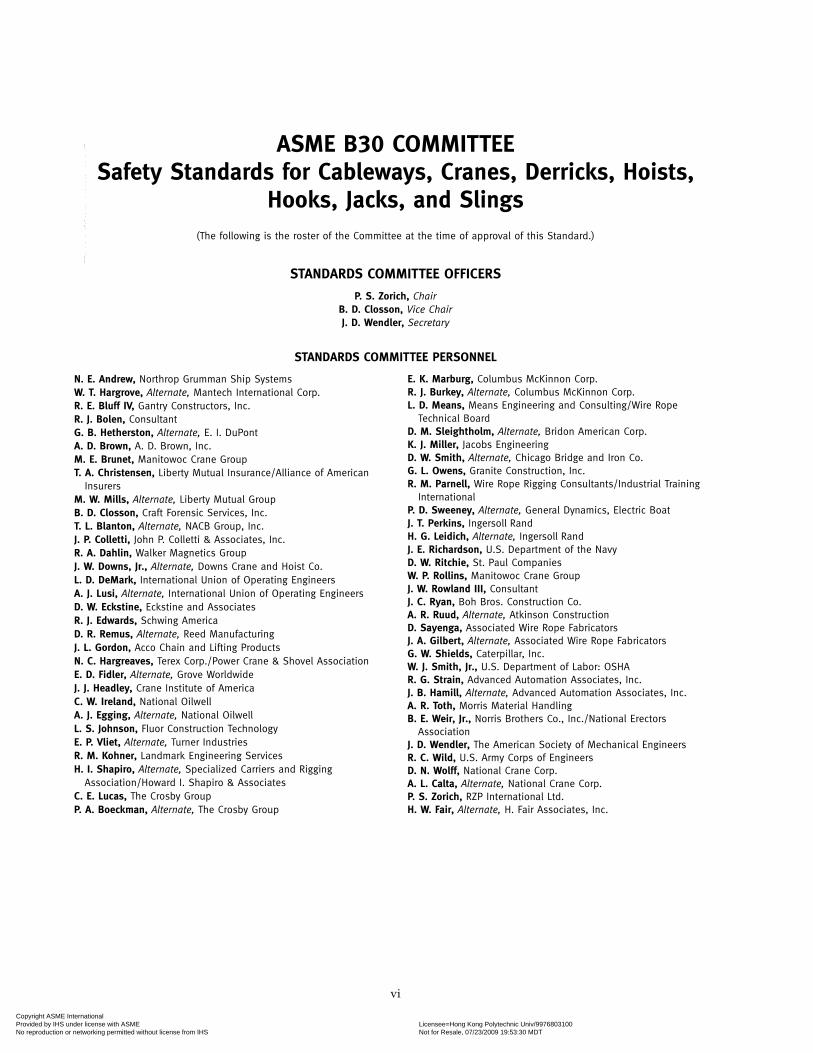
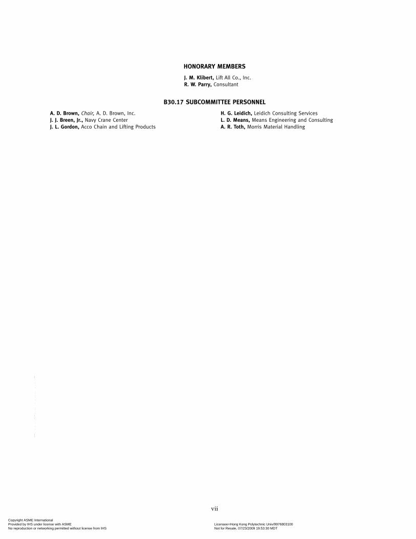
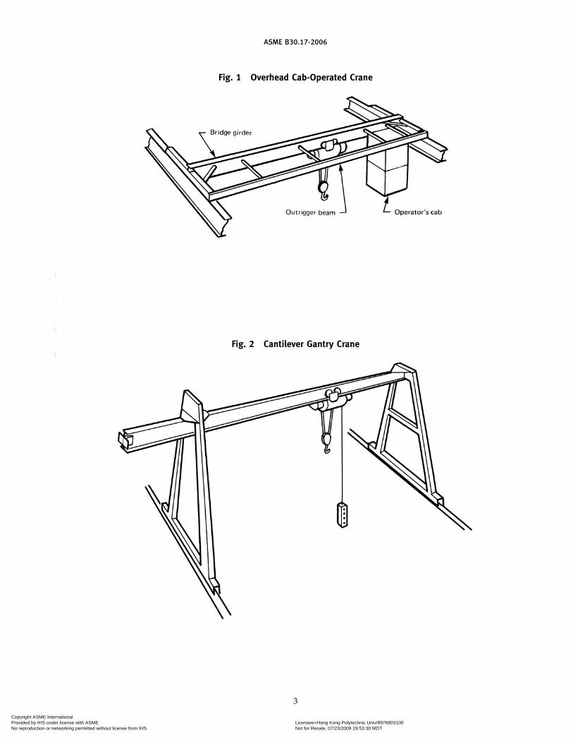
Figures1 Overhead Cab-Operated Crane . . . . . . . . . . . . . . . . . . . . . . . . . . . . . . . . . . . . . . . . 32 Cantilever Gantry Crane . . . . . . . . . . . . . . . . . . . . . . . . . . . . . . . . . . . . . . . . . . . . . . 33 Overhead Floor-Operated Crane . . . . . . . . . . . . . . . . . . . . . . . . . . . . . . . . . . . . . . 44 Gantry Crane . . . . . . . . . . . . . . . . . . . . . . . . . . . . . . . . . . . . . . . . . . . . . . . . . . . . . . . . . 45 Semigantry Crane . . . . . . . . . . . . . . . . . . . . . . . . . . . . . . . . . . . . . . . . . . . . . . . . . . . . . 56 Recommended Arrangement of Controllers or Master Switches
(3-Motor Crane) . . . . . . . . . . . . . . . . . . . . . . . . . . . . . . . . . . . . . . . . . . . . . . . . . . . . 147 Recommended Arrangement of Controllers or Master Switches
(4-Motor Crane) . . . . . . . . . . . . . . . . . . . . . . . . . . . . . . . . . . . . . . . . . . . . . . . . . . . . 158 Recommended Arrangement of Controllers (Pendant Push Button
Station Arrangements) . . . . . . . . . . . . . . . . . . . . . . . . . . . . . . . . . . . . . . . . . . . . . . 16
iii
Copyright ASME International Provided by IHS under license with ASME Licensee=Hong Kong Polytechnic Univ/9976803100
Not for Resale, 07/23/2009 19:53:30 MDTNo reproduction or networking permitted without license from IHS
--`
``
``````
`````
-`-`
``
``---

9 Recommended Arrangement of Controllers (Radio Crane ControlTransmitter Lever Arrangements) . . . . . . . . . . . . . . . . . . . . . . . . . . . . . . . . . . . 16
10 Standard Hand Signals for Controlling Single-Girder Top RunningCranes . . . . . . . . . . . . . . . . . . . . . . . . . . . . . . . . . . . . . . . . . . . . . . . . . . . . . . . . . . . . . 24
iv
Copyright ASME International Provided by IHS under license with ASME Licensee=Hong Kong Polytechnic Univ/9976803100
Not for Resale, 07/23/2009 19:53:30 MDTNo reproduction or networking permitted without license from IHS
` ` ` ` `` `` ` ` `` `` ` ` ` ` ` `
FOREWORD
This American National Standard, Safety Standard for Cableways, Cranes, Derricks, Hoists,Hooks, Jacks, and Slings, has been developed under the procedures accredited by the AmericanNational Standards Institute (ANSI) (formerly the United States of America Standards Institute).This Standard had its beginning in December 1916 when an eight-page Code of Safety Standardsfor Cranes, prepared by an ASME Committee on the Protection of Industrial Workers, waspresented to the annual meeting of ASME.
Meetings and discussions regarding safety on cranes, derricks, and hoists were held from 1920to 1925, involving the ASME Safety Code Correlating Committee, the Association of Iron andSteel Electrical Engineers, the American Museum of Safety, the American Engineering StandardsCommittee (later changed to American Standards Association and subsequently to the USAStandards Institute), Department of Labor — State of New Jersey, Department of Labor andIndustry — State of Pennsylvania, and the Locomotive Crane Manufacturers Association. OnJune 11, 1925, the American Engineering Standards Committee approved the ASME Safety CodeCorrelating Committee’s recommendation and authorized the project, with the U.S. Departmentof the Navy, Bureau of Yards and Docks, and ASME as sponsors.
In March 1926, invitations were issued to 50 organizations to appoint representatives to aSectional Committee. The call for organization of this Sectional Committee was sent out October 2,1926, and the committee organized November 4, 1926, with 57 members representing 29 nationalorganizations. The Safety Code for Cranes, Derricks, and Hoists, ASA B30.2-1943, was createdfrom the eight-page document referred to in the first paragraph. This document was reaffirmedin 1952 and widely accepted as a safety standard.
Due to changes in design, advancement in techniques, and general interest of labor and industryin safety, the Sectional Committee, under the joint sponsorship of ASME and the Naval FacilitiesEngineering Command, U.S. Department of the Navy, was reorganized as an American NationalStandards Committee on January 31, 1962, with 39 members representing 27 national organiza-tions.
The format of the previous code was changed so that separate standards (each complete as toconstruction and installation; inspection, testing, and maintenance; and operation) will cover thedifferent types of equipment included in the scope of B30.
In 1982, the Committee was reorganized as an Accredited Organization Committee, operatingunder procedures developed by ASME and accredited by ANSI.
This Standard presents a coordinated set of rules that may serve as a guide to governmentand other regulatory bodies and municipal authorities responsible for the guarding and inspectionof the equipment falling within its scope. The suggestions leading to accident prevention aregiven both as mandatory and advisory provisions; compliance with both types may be requiredby employers of their employees.
In case of practical difficulties, new developments, or unnecessary hardship, the administrativeor regulatory authority may grant variances from the literal requirements or permit the use ofother devices or methods, but only when it is clearly evident that an equivalent degree ofprotection is thereby secured. To secure uniform application and interpretation of this Standard,administrative or regulatory authorities are urged to consult the B30 Committee, in accordancewith the format described in Section IX, before rendering decisions on disputed points.
This Volume of the Standard, which was approved by the B30 Committee and by ASME, wasapproved by ANSI and designated as an American National Standard on December 20, 2006.
Safety codes and standards are intended to enhance public safety. Revisions result from commit-tee consideration of factors such as technological advances, new data, and changing environmentaland industry needs. Revisions do not imply that previous editions were inadequate.
v
Copyright ASME International Provided by IHS under license with ASME Licensee=Hong Kong Polytechnic Univ/9976803100
Not for Resale, 07/23/2009 19:53:30 MDTNo reproduction or networking permitted without license from IHS
` ` ` ` `` `` ` ` `` `` ` ` ` ` ` `
ASME B30 COMMITTEESafety Standards for Cableways, Cranes, Derricks, Hoists,
Hooks, Jacks, and Slings(The following is the roster of the Committee at the time of approval of this Standard.)
STANDARDS COMMITTEE OFFICERS
P. S. Zorich, ChairB. D. Closson, Vice ChairJ. D. Wendler, Secretary
STANDARDS COMMITTEE PERSONNEL
N. E. Andrew, Northrop Grumman Ship SystemsW. T. Hargrove, Alternate, Mantech International Corp.R. E. Bluff IV, Gantry Constructors, Inc.R. J. Bolen, ConsultantG. B. Hetherston, Alternate, E. I. DuPontA. D. Brown, A. D. Brown, Inc.M. E. Brunet, Manitowoc Crane GroupT. A. Christensen, Liberty Mutual Insurance/Alliance of American
InsurersM. W. Mills, Alternate, Liberty Mutual GroupB. D. Closson, Craft Forensic Services, Inc.T. L. Blanton, Alternate, NACB Group, Inc.J. P. Colletti, John P. Colletti & Associates, Inc.R. A. Dahlin, Walker Magnetics GroupJ. W. Downs, Jr., Alternate, Downs Crane and Hoist Co.L. D. DeMark, International Union of Operating EngineersA. J. Lusi, Alternate, International Union of Operating EngineersD. W. Eckstine, Eckstine and AssociatesR. J. Edwards, Schwing AmericaD. R. Remus, Alternate, Reed ManufacturingJ. L. Gordon, Acco Chain and Lifting ProductsN. C. Hargreaves, Terex Corp./Power Crane & Shovel AssociationE. D. Fidler, Alternate, Grove WorldwideJ. J. Headley, Crane Institute of AmericaC. W. Ireland, National OilwellA. J. Egging, Alternate, National OilwellL. S. Johnson, Fluor Construction TechnologyE. P. Vliet, Alternate, Turner IndustriesR. M. Kohner, Landmark Engineering ServicesH. I. Shapiro, Alternate, Specialized Carriers and Rigging
Association/Howard I. Shapiro & AssociatesC. E. Lucas, The Crosby GroupP. A. Boeckman, Alternate, The Crosby Group
vi
E. K. Marburg, Columbus McKinnon Corp.R. J. Burkey, Alternate, Columbus McKinnon Corp.L. D. Means, Means Engineering and Consulting/Wire Rope
Technical BoardD. M. Sleightholm, Alternate, Bridon American Corp.K. J. Miller, Jacobs EngineeringD. W. Smith, Alternate, Chicago Bridge and Iron Co.G. L. Owens, Granite Construction, Inc.R. M. Parnell, Wire Rope Rigging Consultants/Industrial Training
InternationalP. D. Sweeney, Alternate, General Dynamics, Electric BoatJ. T. Perkins, Ingersoll RandH. G. Leidich, Alternate, Ingersoll RandJ. E. Richardson, U.S. Department of the NavyD. W. Ritchie, St. Paul CompaniesW. P. Rollins, Manitowoc Crane GroupJ. W. Rowland III, ConsultantJ. C. Ryan, Boh Bros. Construction Co.A. R. Ruud, Alternate, Atkinson ConstructionD. Sayenga, Associated Wire Rope FabricatorsJ. A. Gilbert, Alternate, Associated Wire Rope FabricatorsG. W. Shields, Caterpillar, Inc.W. J. Smith, Jr., U.S. Department of Labor: OSHAR. G. Strain, Advanced Automation Associates, Inc.J. B. Hamill, Alternate, Advanced Automation Associates, Inc.A. R. Toth, Morris Material HandlingB. E. Weir, Jr., Norris Brothers Co., Inc./National Erectors
AssociationJ. D. Wendler, The American Society of Mechanical EngineersR. C. Wild, U.S. Army Corps of EngineersD. N. Wolff, National Crane Corp.A. L. Calta, Alternate, National Crane Corp.P. S. Zorich, RZP International Ltd.H. W. Fair, Alternate, H. Fair Associates, Inc.
Copyright ASME International Provided by IHS under license with ASME Licensee=Hong Kong Polytechnic Univ/9976803100
Not for Resale, 07/23/2009 19:53:30 MDTNo reproduction or networking permitted without license from IHS
--`
``
`````
``
``
``
-`-`
```
`---
HONORARY MEMBERS
J. M. Klibert, Lift All Co., Inc.R. W. Parry, Consultant
B30.17 SUBCOMMITTEE PERSONNEL
A. D. Brown, Chair, A. D. Brown, Inc.J. J. Breen, Jr., Navy Crane CenterJ. L. Gordon, Acco Chain and Lifting Products
vii
H. G. Leidich, Leidich Consulting ServicesL. D. Means, Means Engineering and ConsultingA. R. Toth, Morris Material Handling
Copyright ASME International Provided by IHS under license with ASME Licensee=Hong Kong Polytechnic Univ/9976803100
Not for Resale, 07/23/2009 19:53:30 MDTNo reproduction or networking permitted without license from IHS
--`
```
`````
`````
-`-`
``
``---

(06)
SAFETY STANDARD FOR CABLEWAYS, CRANES, DERRICKS, HOISTS,HOOKS, JACKS, AND SLINGS
B30 STANDARD INTRODUCTION
SECTION I: SCOPE
The ASME B30 Standard contains provisions thatapply to the construction, installation, operation, inspec-tion, testing, maintenance, and use of cranes and otherlifting and material-handling related equipment. For theconvenience of the reader, the Standard has been dividedinto separate volumes. Each volume has been writtenunder the direction of the ASME B30 StandardsCommittee and has successfully completed a consensusapproval process under the general auspices of theAmerican National Standards Institute (ANSI).
As of the date of issuance of this Volume, the B30Standard comprises the following volumes:
B30.1 JacksB30.2 Overhead and Gantry Cranes (Top Running
Bridge, Single or Multiple Girder, TopRunning Trolley Hoist)
B30.3 Construction Tower CranesB30.4 Portal, Tower, and Pedestal CranesB30.5 Mobile and Locomotive CranesB30.6 DerricksB30.7 Base Mounted Drum HoistsB30.8 Floating Cranes and Floating DerricksB30.9 SlingsB30.10 HooksB30.11 Monorails and Underhung CranesB30.12 Handling Loads Suspended From RotorcraftB30.13 Storage/Retrieval (S/R) Machines and
Associated EquipmentB30.14 Side Boom TractorsB30.15 Mobile Hydraulic Cranes
(NOTE: B30.15-1973 has been withdrawn.The revision of B30.15 is included in the lat-est edition of B30.5.)
B30.16 Overhead Hoists (Underhung)B30.17 Overhead and Gantry Cranes (Top Running
Bridge, Single Girder, Underhung Hoist)B30.18 Stacker Cranes (Top or Under Running
Bridge, Multiple Girder With Top or UnderRunning Trolley Hoist)
B30.19 CablewaysB30.20 Below-the-Hook Lifting DevicesB30.21 Manually Lever Operated HoistsB30.22 Articulating Boom Cranes
viii
B30.23 Personnel Lifting SystemsB30.24 Container Cranes1
B30.25 Scrap and Material HandlersB30.26 Rigging HardwareB30.27 Material Placement SystemsB30.28 Balance Lifting Units1
SECTION II: SCOPE EXCLUSIONS
The B30 Standard does not apply to track and automo-tive jacks, railway or automobile wrecking cranes, ship-board cranes, shipboard cargo-handling equipment,well-drilling derricks, skip hoists, mine hoists, truckbody hoists, car or barge pullers, conveyors, excavatingequipment, or equipment covered under the scope ofthe following standards: A10, A17, A90, A92, A120, B20,B56, and B77.
SECTION III: PURPOSE
The B30 Standard is intended to(a) prevent or minimize injury to workers, and other-
wise provide for the protection of life, limb, and propertyby prescribing safety requirements
(b) provide direction to manufacturers, owners,employers, users, and others concerned with, or respon-sible for, its application
(c) guide governments and other regulatory bodiesin the development, promulgation, and enforcement ofappropriate safety directives
SECTION IV: USE BY REGULATORY AGENCIES
These Volumes may be adopted in whole or in partfor governmental or regulatory use. If adopted for gov-ernmental use, the references to other national codesand standards in the specific volumes may be changedto refer to the corresponding regulations of the govern-mental authorities.
SECTION V: EFFECTIVE DATE
(a) Effective Date. The effective date of this Volume ofthe B30 Standard shall be 1 year after its date of issuance.
1 These volumes are currently in the development process.
Copyright ASME International Provided by IHS under license with ASME Licensee=Hong Kong Polytechnic Univ/9976803100
Not for Resale, 07/23/2009 19:53:30 MDTNo reproduction or networking permitted without license from IHS
--`
``
`````
``
``
``
-`-`
``
``---

Construction, installation, inspection, testing, mainte-nance, and operation of equipment manufactured andfacilities constructed after the effective date of thisVolume shall conform to the mandatory requirementsof this Volume.
(b) Existing Installations. Equipment manufacturedand facilities constructed prior to the effective date ofthis Volume of the B30 Standard shall be subject to theinspection, testing, maintenance, and operation require-ments of this Standard after the effective date.
It is not the intent of this Volume of the B30 Standardto require retrofitting of existing equipment. However,when an item is being modified, its performance require-ments shall be reviewed relative to the requirementswithin the current volume. The need to meet the currentrequirements shall be evaluated by a qualified personselected by the owner (user). Recommended changesshall be made by the owner (user) within 1 year.
SECTION VI: REQUIREMENTS ANDRECOMMENDATIONS
Requirements of this Standard are characterized byuse of the word shall. Recommendations of this Standardare characterized by the word should.
SECTION VII: USE OF MEASUREMENT UNITS
This Standard contains SI (metric) units as well asU.S. Customary units. The values stated in customaryunits are to be regarded as the standard. The SI unitsare a direct (soft) conversion from the customary units.
SECTION VIII: REQUESTS FOR REVISION
The B30 Standards Committee will consider requestsfor revision of any of the volumes within the B30Standard. Such requests should be directed to
Secretary, B30 Standards CommitteeASME Codes and StandardsThree Park AvenueNew York, NY 10016-5990
The requests should be in the following format:
Volume: Cite the designation and title of the volume.
Edition: Cite the applicable edition of the volume.
Subject: Cite the applicable paragraph number(s)and the relevant heading(s).
Request: Indicate the suggested revision.
Rationale: State the rationale for the suggestedrevision.
Upon receipt by the Secretary, the request will beforwarded to the relevant B30 Subcommittee for consid-eration and action. Correspondence will be provided to
ix
the requester defining the actions undertaken by theB30 Standards Committee.
SECTION IX: REQUESTS FOR INTERPRETATION
The B30 Standards Committee will render an interpre-tation of the provisions of the B30 Standard. Suchrequests should be directed to
Secretary, B30 Standards CommitteeASME Codes and StandardsThree Park AvenueNew York, NY 10016-5990
The requests should be in the following format:
Volume: Cite the designation and title of the volume.
Edition: Cite the applicable edition of the volume.
Subject: Cite the applicable paragraph number(s)and the relevant heading(s).
Question: Phrase the question as a request for an inter-pretation of a specific provision suitable forgeneral understanding and use, not as arequest for approval of a proprietary designor situation. Plans or drawings that explainthe question may be submitted to clarify thequestion. However, they should not containany proprietary names or information.
Upon receipt by the Secretary, the request will beforwarded to the relevant B30 Subcommittee for a draftresponse, which will then be subject to approval by theB30 Standards Committee prior to its formal issuance.
Interpretations to the B30 Standard will be publishedin the subsequent edition of the respective volume andwill be available online at http://cstools.asme.org.
SECTION X: ADDITIONAL GUIDANCE
The equipment covered by the B30 Standard is subjectto hazards that cannot be abated by mechanical means,but only by the exercise of intelligence, care, and com-mon sense. It is therefore essential to have personnelinvolved in the use and operation of equipment whoare competent, careful, physically and mentally quali-fied, and trained in the proper operation of the equip-ment and the handling of loads. Serious hazards include,but are not limited to, improper or inadequate mainte-nance, overloading, dropping or slipping of the load,obstructing the free passage of the load, and using equip-ment for a purpose for which it was not intended ordesigned.
The B30 Standards Committee fully realizes theimportance of proper design factors, minimum or maxi-mum dimensions, and other limiting criteria of wirerope or chain and their fastenings, sheaves, sprockets,
Copyright ASME International Provided by IHS under license with ASME Licensee=Hong Kong Polytechnic Univ/9976803100
Not for Resale, 07/23/2009 19:53:30 MDTNo reproduction or networking permitted without license from IHS
--`
``
`````
``
``
``
-`-`
``
``---
drums, and similar equipment covered by the standard,all of which are closely connected with safety. Sizes,strengths, and similar criteria are dependent on manydifferent factors, often varying with the installation anduses. These factors depend on
(a) the condition of the equipment or material(b) the loads(c) the acceleration or speed of the ropes, chains,
sheaves, sprockets, or drums
x
(d) the type of attachments(e) the number, size, and arrangement of sheaves or
other parts(f) environmental conditions causing corrosion or
wear(g) many variables that must be considered in each
individual caseThe requirements and recommendations provided in
the volumes must be interpreted accordingly, and judg-ment used in determining their application.
Copyright ASME International Provided by IHS under license with ASME Licensee=Hong Kong Polytechnic Univ/9976803100
Not for Resale, 07/23/2009 19:53:30 MDTNo reproduction or networking permitted without license from IHS
--`
```
``
``
``
``
``-`-`
``
``---

ASME B30.17-2006SUMMARY OF CHANGES
Following approval by the ASME B30 Standards Committee and ASME, and after public review,ASME B30.17-2006 was approved by the American National Standards Institute onDecember 20, 2006.
ASME B30.17-2006 includes editorial changes, revisions, and corrections identified by a marginnote, (06).
Page Location Change
vii-x Introduction Revised
2 Definitions crane operator, dedicated and crane operator,nondedicated added
13 17-1.13.3(j) Added
22 17-3.2.1.1 Subparagraphs (b), (c), and (e)(2) revised
xi
Copyright ASME International Provided by IHS under license with ASME Licensee=Hong Kong Polytechnic Univ/9976803100
Not for Resale, 07/23/2009 19:53:30 MDTNo reproduction or networking permitted without license from IHS
--`
``
`````
``
``
``
-`-`
``
``---

xii
Copyright ASME International Provided by IHS under license with ASME Licensee=Hong Kong Polytechnic Univ/9976803100
Not for Resale, 07/23/2009 19:53:30 MDTNo reproduction or networking permitted without license from IHS
--`
``
`````
``
``
``
-`-`
``
``---

ASME B30.17-2006
OVERHEAD AND GANTRY CRANES (TOP RUNNING BRIDGE,SINGLE GIRDER, UNDERHUNG HOIST)
Chapter 17-0Scope, Definitions, and References
SECTION 17-0.1: SCOPE OF B30.17
Volume B30.17 includes provisions that apply to theconstruction, installation, operation, inspection, andmaintenance of hand-operated and power-driven over-head and gantry cranes that have a top-running single-girder bridge, with one or more underhung hoists (seeB30.16 Volume) operating on the lower flange of thebridge girder, used for vertical lifting and lowering offreely suspended, unguided loads (see Figs. 1 through5). The requirements included in this Volume also applyto cranes having the same fundamental characteristicssuch as polar gantry cranes, cantilever gantry cranes,semigantry cranes, and wall cranes.
Requirements for a crane used for a special purposesuch as, but not limited to, nonvertical lifting service,lifting a guided load, or lifting personnel are notincluded in this Volume.
SECTION 17-0.2: DEFINITIONS
abnormal operating conditions: environmental conditionsthat are unfavorable, harmful, or detrimental to or forthe operation of a crane, such as excessively high orlow ambient temperatures, exposure to adverse weather,corrosive fumes, dust-laden or moisture-laden atmo-spheres, and hazardous locations.
administrative or regulatory authority: governmentalagency, or the employer in the absence of governmentaljurisdiction.
appointed: assigned specific responsibilities by theemployer or the employer’s representative.
authorized: appointed by a duly constituted administra-tive or regulatory authority.
brake: a device, other than a motor, used for retardingor stopping motion by friction or power means.
braking, control: a method of controlling speed by remov-ing energy from the moving body or by impartingenergy in the opposite direction.
1
braking, countertorque (plugging): a method of controllingspeed by reversing the motor line voltage polarity orphase sequence to develop torque in the direction oppo-site to the rotation of the motor.
braking, dynamic: a method of controlling speed by usingthe motor as a generator, with the energy being dissi-pated in resistors.
braking, eddy current: a method of controlling or reducingspeed by means of an electrical induction load brake.
braking, emergency: a method of decelerating a drivewhen power is not available. The braking effort maybe established as a result of action by the operator, orautomatically when power to the drive is interrupted.
braking, hydraulic: a method of controlling or reducingspeed by means of displacement of a liquid.
braking means: a method or device used for stopping/holding motion by friction or power.
braking, mechanical: a method of controlling or reducingspeed by friction.
braking, pneumatic: a method of controlling or poweringa drive or brake by means of compressed gas.
braking, regenerative: a method of controlling speed inwhich the electrical energy generated by the motor isfed back into the power system.
braking, service: a method to decelerate crane motionduring normal operation.
bridge: the part of an overhead crane, consisting of onegirder, trucks, and (if applicable) drive mechanism, thatcarries the trolley or trolleys.
bridge girder: a crane member on which carriers or trol-leys travel horizontally, mounted between and sup-ported by the end trucks.
bridge travel: the crane movement in a direction parallelto the crane runway.
bumper (buffer): a device for reducing impact when amoving crane or trolley reaches the end of its permittedtravel, or when two moving cranes or trolleys come
Copyright ASME International Provided by IHS under license with ASME Licensee=Hong Kong Polytechnic Univ/9976803100
Not for Resale, 07/23/2009 19:53:30 MDTNo reproduction or networking permitted without license from IHS
--`
``
`````
``
``
``
-`-`
``
``---

ASME B30.17-2006
into contact. This device may be attached to the bridge,trolley, or runway stop.
cab: the operator’s compartment on a crane.
cab, skeleton: the operator’s compartment used for occa-sional cab operation of a normally floor- or remote-operated crane.
chain, hand: the chain grasped by the operator to applyforce required for lifting, lowering, or travelingmotions.1
chain, load: the load-bearing chain in a hoist.1
clearance: the distance from any part of the crane to thenearest obstruction.
collectors, current: contacting devices for conducting cur-rent from runway or bridge conductors.
conductors, bridge: the electrical conductors located alongthe bridge structure of a crane that transmit control sig-nals and power to the trolley(s).
conductors, runway (main): the electrical conductorslocated along a crane runway that transmit control sig-nals and power to the crane.
control panel: an assembly of components (e.g., magnetic,static, hydraulic, pneumatic, etc.) that governs the flowof power to or from a motor or other equipment inresponse to signals from a master switch, push buttonstation, remote control, automatic program control, etc.
controller: a device or group of devices that serves togovern, in a predetermined manner, the power delivereddirectly to the apparatus to which it is connected.
controller, manual: a controller having all of its basic func-tions performed by devices that are operated by hand.
controller, spring-return: a controller that, when released,will return automatically to a neutral (“OFF”) position.
crane: a machine for lifting and lowering a load, andmoving it horizontally. Cranes, whether fixed or mobile,are driven manually, by power, or by a combinationof both.
crane, automatic: a crane that, when activated, operatesthrough a preset cycle or cycles.
crane, cab-operated: a crane whose movements are con-trolled by an operator through the use of controllerslocated in a cab that is attached to the crane (refer toFig. 1).
crane, cantilever gantry: a gantry or semigantry crane inwhich the bridge girders or trusses extend transverselybeyond the crane runway on one or both sides (refer toFig. 2).
crane, floor-operated: a crane whose movements are con-trolled by an operator through the use of controllers
1 Hand and load chain properties do not conform to those shownin ASME B30.9.
2
contained in a pendant station suspended from the crane(refer to Fig. 3).
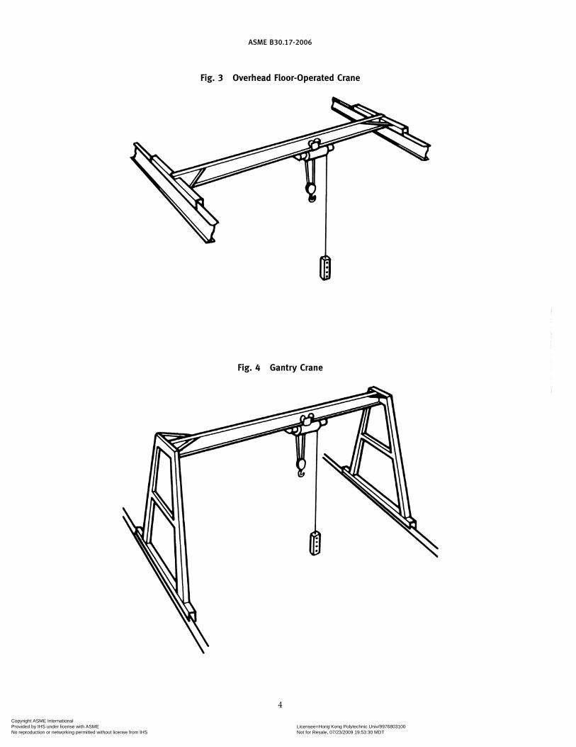
crane, gantry: a crane similar to an overhead crane, exceptthat the bridge for carrying the trolley or trolleys isrigidly supported on two or more legs running on fixedrails or other runway (refer to Fig. 4).
crane, hot molten material-handling: an overhead craneused for transporting or pouring molten material.
crane, manually operated: a crane whose hoist mechanismis driven by pulling an endless chain or whose travelmechanism is driven in the same manner or by manuallymoving the load.
crane operator, dedicated: an employee whose job is con-fined solely to the operation of an overhead or gantrycrane.
crane operator, nondedicated: an employee who uses anoverhead or gantry crane as a tool to assist in the per-formance of his/her regular job.
crane, outdoor: an overhead or gantry crane that operatesoutdoors and for which provisions are not available forstorage in an area that provides protection to the cranefrom weather conditions. An indoor crane that mayoperate outdoors on a periodic basis is not classified asan outdoor crane.
crane, overhead: a crane with a movable bridge carryinga movable or fixed hoisting mechanism and travelingon an overhead, fixed runway structure (refer to Figs. 1and 3 for the types covered by this Volume).
crane, power-operated: a crane whose mechanism is drivenby electric, pneumatic, hydraulic, or internal combustionmeans.
crane, pulpit-operated: a crane whose movements are con-trolled by an operator through the use of controllerslocated in a control room, a fixed or movable cab, or aplatform that is independent of the crane.
crane, remote-operated: a crane whose movements are con-trolled by an operator through the use of controllerscontained in a portable operating station not attachedto the crane.
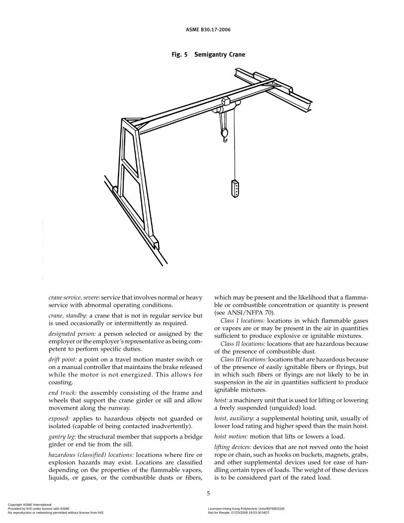
crane, semigantry: a gantry crane with one end of thebridge rigidly supported on one or more legs that runon a fixed rail or runway, the other end of the bridgebeing supported by an end truck running on an elevatedrail or runway (refer to Fig. 5).
crane service, heavy: service that involves operation withinthe rated load limit that exceeds normal service.
crane service, normal: service that involves operation withrandomly distributed loads within the rated load limit,or with uniform loads of less than 65% of the rated load,for no more than 15% of the time of a single work shiftfor manually operated cranes and 25% of the time of asingle work shift for electrically pneumatically poweredcranes.
(06)
(06)
Copyright ASME International Provided by IHS under license with ASME Licensee=Hong Kong Polytechnic Univ/9976803100
Not for Resale, 07/23/2009 19:53:30 MDTNo reproduction or networking permitted without license from IHS
--`
``
`````
``
````
-`-`
```
`---
ASME B30.17-2006
Fig. 1 Overhead Cab-Operated Crane
Fig. 2 Cantilever Gantry Crane
3
Copyright ASME International Provided by IHS under license with ASME Licensee=Hong Kong Polytechnic Univ/9976803100
Not for Resale, 07/23/2009 19:53:30 MDTNo reproduction or networking permitted without license from IHS
--`
``
`````
``
``
``
-`-`
``
``---
ASME B30.17-2006
Fig. 3 Overhead Floor-Operated Crane
Fig. 4 Gantry Crane
4
Copyright ASME International Provided by IHS under license with ASME Licensee=Hong Kong Polytechnic Univ/9976803100
Not for Resale, 07/23/2009 19:53:30 MDTNo reproduction or networking permitted without license from IHS
--`
``
`````
``
``
``
-`-`
``
``---
ASME B30.17-2006
Fig. 5 Semigantry Crane
crane service, severe: service that involves normal or heavyservice with abnormal operating conditions.
crane, standby: a crane that is not in regular service butis used occasionally or intermittently as required.
designated person: a person selected or assigned by theemployer or the employer’s representative as being com-petent to perform specific duties.
drift point: a point on a travel motion master switch oron a manual controller that maintains the brake releasedwhile the motor is not energized. This allows forcoasting.
end truck: the assembly consisting of the frame andwheels that support the crane girder or sill and allowmovement along the runway.
exposed: applies to hazardous objects not guarded orisolated (capable of being contacted inadvertently).
gantry leg: the structural member that supports a bridgegirder or end tie from the sill.
hazardous (classified) locations: locations where fire orexplosion hazards may exist. Locations are classifieddepending on the properties of the flammable vapors,liquids, or gases, or the combustible dusts or fibers,
5
which may be present and the likelihood that a flamma-ble or combustible concentration or quantity is present(see ANSI/NFPA 70).
Class I locations: locations in which flammable gasesor vapors are or may be present in the air in quantitiessufficient to produce explosive or ignitable mixtures.
Class II locations: locations that are hazardous becauseof the presence of combustible dust.
Class III locations: locations that are hazardous becauseof the presence of easily ignitable fibers or flyings, butin which such fibers or flyings are not likely to be insuspension in the air in quantities sufficient to produceignitable mixtures.
hoist: a machinery unit that is used for lifting or loweringa freely suspended (unguided) load.
hoist, auxiliary: a supplemental hoisting unit, usually oflower load rating and higher speed than the main hoist.
hoist motion: motion that lifts or lowers a load.
lifting devices: devices that are not reeved onto the hoistrope or chain, such as hooks on buckets, magnets, grabs,and other supplemental devices used for ease of han-dling certain types of loads. The weight of these devicesis to be considered part of the rated load.
Copyright ASME International Provided by IHS under license with ASME Licensee=Hong Kong Polytechnic Univ/9976803100
Not for Resale, 07/23/2009 19:53:30 MDTNo reproduction or networking permitted without license from IHS
--`
``
`````
``
``
``
-`-`
``
``---

ASME B30.17-2006
load: the total superimposed weight on the load blockor hook.
load block: the assembly of hook or shackle, swivel, bear-ing, sheaves, pins, and frame suspended by the hoistingrope or load chain. This shall include any appurtenancesreeved in the hoisting rope or load chain.
load, rated: the maximum load designated by the manu-facturer for which a crane or individual hoist is designedand built.
master switch: see switch, master.
noncoasting mechanical drive: a drive that automaticallyresults in decelerating a trolley or bridge when poweris not available.
normal operating conditions (of cab-operated cranes): condi-tions during which a crane is performing functionswithin the scope of the original design. Under theseconditions, the operator is at the operating controldevices and no other person is on the crane.
normal operating conditions (of floor-operated cranes): condi-tions during which a crane is performing functionswithin the scope of the original design. Under theseconditions, the operator is at the operating controldevices that are attached to the crane, but it is operatedwith the operator off the crane and with no person onthe crane.
normal operating conditions (of remote-operated cranes): con-ditions during which a crane is performing functionswithin the scope of the original design. Under theseconditions, the operator is at the operating controldevices that are not attached to any part of the craneand no person is on the crane.
overload: any load greater than the rated load.
pendant station: controls suspended from the crane foroperating the unit from the floor.
qualified person: a person who, by possession of a recog-nized degree in an applicable field or certificate of pro-fessional standing or by extensive knowledge, training,and experience, has successfully demonstrated the abil-ity to solve or resolve problems relating to the subjectmatter and work.
rail sweep: a device attached to the crane and located infront of the crane’s leading wheels to push aside looseobstructions.
rope: refers to wire rope unless otherwise specified.
runway: an assembly of rails, beams, girders, brackets,and framework on which the crane travels.
service platform: a means provided for workers to performmaintenance, inspections, adjustments, and repairs ofcranes.
shall: use of this word indicates that a rule is mandatoryand must be followed.
6
should: use of this word indicates that a rule is a recom-mendation, the advisability of which depends on thefacts in each situation.
side pull: the component of the hoist pull acting horizon-tally when the hoist lines are not operated vertically.
sills: horizontal structural members that connect thelower ends of two or more legs of a gantry crane onone runway.
span: the horizontal distance, center to center, betweenrunway rails.
stop: a device to limit travel of a trolley or crane bridge.This device normally is attached to a fixed structure andnormally does not have energy absorbing ability.
switch (valve): a device for making, breaking, or changingthe connections in an electric, hydraulic, or pneumaticcircuit.
switch, emergency stop: a manually actuated switch todisconnect power independently of the regularoperating controls.
switch, limit: a device that is actuated by the motion ofa part of a power-driven machine or equipment to alteror disconnect the electric, hydraulic, or pneumatic circuitassociated with the machine or equipment.
switch, main (crane disconnect): a switch on the cranecontrolling the main power supply from the runwayconductors.
switch, master: switch that dominates the operation ofcontractors, relays, or other remotely operated devices.
switch, master, spring-return: a master switch that, whenreleased, will return automatically to a neutral (“OFF”)position.
switch, runway disconnect: a switch, usually at floor level,controlling the main power supply to the runway con-ductors.
trolley (carrier): the unit that travels on the bottom flangeof the bridge girder and carries the hoist.
trolley travel: the trolley movement in directions at rightangles to the crane runway.
unattended: a condition in which the operator of a crane isnot at the operating control devices. On a floor-operatedcrane, however, if the operating control devices arewithin sight of the operator and within a distance equalto the span of the crane, the crane should be consideredattended.
SECTION 17-0.3: REFERENCES
The following is a list of publications referenced inthis Volume:
ANSI A14.3-1992, Safety Requirements for FixedLadders
Copyright ASME International Provided by IHS under license with ASME Licensee=Hong Kong Polytechnic Univ/9976803100
Not for Resale, 07/23/2009 19:53:30 MDTNo reproduction or networking permitted without license from IHS
` ` ` ` `` `` ` ` `` `` ` ` ` ` ` `

ASME B30.17-2006
ANSI Z244.1-1982 (R1993), Safety Requirements for theLock Out/Tag Out of Energy Sources
Publisher: American National Standards Institute(ANSI), 25 West 43rd Street, New York, NY 10036
ANSI/AFS Z241.2-1999, Safety Requirements forMelting and Pouring of Metals in the Metal CastingIndustry2
Publisher: American Foundry Society (AFS), 1695 NorthPenny Lane, Schaumburg, IL 60173-4555
ANSI/ASCE 7-95, Minimum Design Loads for Buildingsand Other Structures2
Publisher: American Society of Civil Engineers (ASCE),1801 Alexander Bell Drive, Reston, VA 20191-4400
ANSI/ASSE A1264.1-1995, Safety Requirements forWorkplace Floor and Wall Openings, Stairs, andRailing Systems2
Publisher: The American Society of Safety Engineers(ASSE), 1800 East Oakton Street, Des Plaines, IL 60018
ANSI/AWS D1.1-2002, Structural Welding Code —Steel2
ANSI/AWS D14.1-97, Specification for Welding ofIndustrial and Mill Cranes and Other MaterialHandling Equipment2
Publisher: American Welding Society (AWS), 550 NWLe Jeune Road, Miami, FL 33126
ANSI/NEMA Z535.4-1998, Product Safety Signs andLabels2
2 May also be obtained from American National Standards Insti-tute, Inc., 25 West 43rd Street, New York, NY 10036.
7
Publisher: National Electrical Manufacturers Associa-tion (NEMA), 1300 North 17th Street, Rosslyn, VA22209
ANSI/NFPA 70-2002, National Electrical CodePublisher: National Fire Protection Association (NFPA),
1 Batterymarch Park, Quincy, MA 02169-7471
ANSI/SAE Z26.1-1996, Safety Glazing Materials forGlazing Motor Vehicles and Motor Vehicles Operatingon Land Highways — Safety Standard2
Publisher: Society of Automotive Engineers (SAE), 400Commonwealth Drive, Warrendale, PA 15096-0001
ASME B15.1-2000, Safety Standard for MechanicalPower Transmission Apparatus2
ASME B30.9-1996, Slings2
ASME B30.10-1999, Hooks2
ASME B30.16-1998, Overhead Hoists (Underhung)2
ASME B30.20-1999, Below-the-Hook Lifting Devices2
Publisher: The American Society of MechanicalEngineers (ASME), Three Park Avenue, New York,NY 10016-5990; Order Department: 22 Law Drive, Box2300, Fairfield, NJ 07007-2300
CMAA Specification No. 74, Revised 2000, Specificationfor Top Running and Under Running Single GirderElectric Overhead Traveling Cranes Utilizing UnderRunning Trolley Hoist
Publisher: Crane Manufacturers Association of America,Inc., (CMAA), 8720 Red Oak Boulevard, Charlotte,NC 28217
LRFD Manual of Steel Construction 2nd Edition, 2ndRevision (1998)
Publisher: American Institute of Steel Construction, Inc.,(AISC), One East Wacker Drive, Chicago, IL60601-1802
Copyright ASME International Provided by IHS under license with ASME Licensee=Hong Kong Polytechnic Univ/9976803100
Not for Resale, 07/23/2009 19:53:30 MDTNo reproduction or networking permitted without license from IHS
` ` ` ` `` `` ` ` `` `` ` ` ` ` ` `
ASME B30.17-2006
Chapter 17-1General Construction and Installation
SECTION 17-1.1: MARKINGS
17-1.1.1 Rated Load Markings — Crane
The rated load of the crane shall be marked on eachside of the crane bridge girder, or other componentattached to the crane bridge girder, and shall be legiblefrom the ground or floor.
17-1.1.2 Rated Load Markings — Hoist
(a) The rated load of the hoist shall be marked on thehoist or trolley unit or its load block and shall be legiblefrom the ground or floor.
(b) If the crane has more than one hoisting unit, eachhoist shall have its rated load marked on the hoist ortrolley unit or its load block and each rated load markingshall be legible from the ground or floor.
(c) The combined load applied to all hoists on a craneshall not exceed the rated load of the crane.
17-1.1.3 Manufacturer’s Identification Markings
The crane shall be marked with manufacturer’s identi-fication information, on a plate or label attached to thecrane, as follows:
(a) name and address of manufacturer(b) manufacturer’s model or serial number(c) voltage of AC or DC power supply and phase and
frequency of AC power supply
17-1.1.4 Multiple Hoist Identification Markings
If the crane has more than one hoisting unit, eachhoist shall have an identification marking on the hoistor trolley unit or its load block (e.g., #1 and #2, A andB, north and south, etc.) and shall be legible from theground or floor. These markings shall also appear onthe controllers used by the operator to indicate the con-trollers that operate each hoist.
17-1.1.5 Warnings
(a) Floor-operated and remote-operated cranes shallhave a safety label or labels affixed to the pendant stationor load block. The label or labels shall be in compliancewith ANSI/NEMA Z535.1, ANSI/NEMA Z535.3,ANSI/NEMA Z535.4, and shall include cautionary lan-guage against
(1) lifting more than rated load(2) operating hoist when load is not centered
under hoist
8
(3) operating hoist with twisted, kinked, or dam-aged chain or rope
(4) operating damaged or malfunctioning crane(5) lifting people(6) lifting loads over people(7) operating a rope hoist with a rope that is not
properly seated in its groove(8) operating manual motions with other than man-
ual power(9) removing or obscuring safety label
(b) Cab-operated and pulpit-operated cranes shallhave a safety label or labels affixed in the cab or pulpit.The label or labels shall be in compliance with ANSI/NEMA Z535.1, ANSI/NEMA Z535.3, ANSI/NEMAZ535.4, and shall include cautionary language against
(1) lifting more than rated load(2) operating hoist when load is not centered
under hoist(3) operating hoist with twisted, kinked, or dam-
aged chain or rope(4) operating damaged or malfunctioning crane(5) lifting people(6) lifting loads over people(7) operating a rope hoist with a rope that is not
properly seated in its groove(8) removing or obscuring safety label
(c) A label shall be affixed on all electrical controlenclosures. The label shall be in compliance with ANSI/NEMA Z535.4 and shall include, but not be limited to,information such as
(1) Disconnect power and lockout/tagout discon-necting means before removing cover or servicing thisequipment.
(2) Do not operate without cover in place.
SECTION 17-1.2: CLEARANCES
17-1.2.1 Clearance From Obstruction
(a) Clearance shall be maintained between the craneand the building, as well as between parallel runningcranes and cranes operating at different elevation, underall operating conditions. In the design of new cranes,all factors that influence clearance, such as wheel float,truss sag, bridge skewing, or trolley positions and con-figurations shall be considered.
(b) Where passageways or walkways are provided onthe structure supporting the crane, obstructions shall
Copyright ASME International Provided by IHS under license with ASME Licensee=Hong Kong Polytechnic Univ/9976803100
Not for Resale, 07/23/2009 19:53:30 MDTNo reproduction or networking permitted without license from IHS
--`
``
`````
``
``
``
-`-`
``
``---
ASME B30.17-2006
not be placed so that personnel will be jeopardized bymovements of the crane.
17-1.2.2 Clearance Between Parallel Cranes
If the runways of two cranes are parallel and thereare no intervening walls or structures, there shall beclearance provided and maintained between the twobridges.
SECTION 17-1.3: GENERAL CONSTRUCTION —RUNWAYS AND SUPPORTINGSTRUCTURE
17-1.3.1 Foundations and Anchorage
(a) Permanent concrete or masonry foundations shallrest on footings below the frost line, except in perma-frost.
(b) Every outdoor crane shall be provided with securefastenings convenient to apply and to hold the craneagainst a wind pressure of 30 lb/ft2 (1 436 Pa). Parkingbrakes may be considered to provide minimum compli-ance with this rule.
(c) Where wind forces are specified to be in excess of30 lb/ft2 (1 436 Pa), special anchorages such as latchesor tie downs at the home position or remotely operatedrail clamps for all positions to supplement the primarybraking system shall be provided (ANSI/ASCE 7 maybe used as a reference for this condition).
(d) Outdoor gantry cranes shall be provided withremotely operated rail clamps or other equivalentdevices. Parking brakes may be considered for a mini-mum compliance with this rule.
(e) Rail clamps should only be applied when the craneis not in motion.
(f) When rails are used for anchorages, they shall besecured to withstand the resultant forces applied by therail clamps. If the clamps act on the rail, any projectionor obstruction in the clamping area shall be avoided.
(g) A wind-indicating device shall be provided for alloutdoor cranes. The device shall be mounted on thecrane or the crane runway structure and shall give avisible and audible alarm to the crane operator at apredetermined wind velocity. A single wind-indicatingdevice may serve as an alarm for more than one crane.
17-1.3.2 Crane Runways
(a) Construction of Runways and Rails(1) The crane runways and supporting structures
shall be designed to withstand the loads and forcesimposed by the crane.
(2) Runway columns shall be securely anchored tofoundations.
(3) The structure shall be free from detrimentalvibration under normal operating conditions.
9
(4) Rails shall be level, straight, joined, and spacedto crane span within recommended tolerances as speci-fied in CMAA Specification No. 74, or within tolerancesspecified by the crane manufacturer or a qualified per-son compatible with the design of the crane.
(5) Where curves are required, special design willbe necessary.
(6) Where grades are required, special design willbe necessary.
(b) Runway Stops(1) Stops shall be provided at limits of travel of the
bridge.(2) Stops shall engage the bumper or bumper pads
mounted on a power-driven bridge. On a hand-operatedbridge, the stops should engage parts of the crane otherthan the wheel. If a stop engages the tread of the wheel,its height shall be no less than the radius of the wheel.
(3) Stops for a power driven bridge shall bedesigned to withstand the forces applied to the bumpers,as specified in para. 17-1.8.2(b).
(4) Stops for a hand-operated bridge shall bedesigned to withstand the forces applied to them.
SECTION 17-1.4: CRANE CONSTRUCTION
17-1.4.1 Welded Construction
All welding procedures and welding operating quali-fications to be used on load-sustaining members shallbe in accordance with ANSI/AWS D1.1, except as modi-fied by ANSI/AWS D14.1. Where special steels or othermaterials are used, the manufacturer or qualified personshall provide welding procedures.
17-1.4.2 Girders
All cranes built after the issuance of this volumeshould conform to the minimum design parameters asspecified in CMAA Specification No. 74.
17-1.4.3 Modifications
Cranes may be modified or rerated, provided suchmodifications and the supporting structure are analyzedthoroughly and approved by a qualified person or man-ufacturer of cranes. A rerated crane or one whose load-supporting components have been modified shall betested in accordance with para. 17-2.2.2. The new ratedload shall be displayed in accordance with paras. 17-1.1.1and 17-1.1.2.
SECTION 17-1.5: CABS — NORMAL OR SKELETON(IF PROVIDED)
17-1.5.1 Cab Location
(a) The general arrangement of the cab and the loca-tion of the control and protective equipment should besuch that all operating and control devices are withinconvenient reach of the operator when facing the area
Copyright ASME International Provided by IHS under license with ASME Licensee=Hong Kong Polytechnic Univ/9976803100
Not for Resale, 07/23/2009 19:53:30 MDTNo reproduction or networking permitted without license from IHS
--`
``
`````
``
``
``
-`-`
``
``---
ASME B30.17-2006
to be served by the load block or when facing the direc-tion of travel of the cab.
(b) The arrangement of the cab should allow the oper-ator a full view of the load block in all positions. Thisis an important and desirable condition, but it is recog-nized that there are physical arrangements that maymake this impossible. When the load block is in thesepositions, the operator shall be aided by other means,such as, but not limited to, closed circuit television,mirrors, radio, telephone, or signal person.
(c) The cab shall be clear of all fixed structures withinits area of possible movement.
(d) The clearance of the cab above the working flooror passageway should be no less than 7 ft (2.1 m), exceptwhen the operations require dimensions that are less.In this case, precautions shall be taken during the opera-tion of the crane to keep personnel and other obstruc-tions clear of the low overhead.
17-1.5.2 Cab Construction
(a) The cab shall be constructed and attached to thecrane to minimize swaying or vibration.
(b) If an integral outside platform is provided, thedoor, if provided, shall be a sliding type or shall openoutward.
(c) In the absence of an outside platform, the door, ifprovided, shall open inward or slide and shall be self-closing. It shall be equipped with a positive latchingdevice to prevent inadvertent opening.
(d) The width of a doorway shall have a clear openingof no less than 18 in. (460 mm).
(e) A trap door, if provided, above the cab or in thecab roof shall have a clear opening of no less than 24 in.(610 mm) on each side. There should be no obstructionsto prevent complete opening of the trap door.
(f) Guard railings and toeboards shall be in compli-ance with ANSI A1264.1.
(g) Outdoor cabs should be enclosed. All cab glazingshall be safety glazing material as defined in ANSI/SAEZ26.1.
(h) The cab construction shall offer protection fromfalling objects, if this possibility exists. The protectionshall support 50 lb/ft2 (2 400 Pa) static load.
(i) If the cab of a molten material crane is exposed toheat, it shall be provided with the following, or equiva-lent, protection:
(1) cab enclosed as for outdoor operation(2) windows with metal sash and heat-resisting
safety glazing material, as defined in ANSI/SAE Z26.1(3) floor insulated with heat-resistant material(4) a shield of metal at least 1⁄8 in. (3 mm) thick
located at least 6 in. (152 mm) below bottom of cab floor(5) materials that will not propagate combustion
or rekindle
10
17-1.5.3 Access to Cab
Access to the cab or bridge service platform shall beby a fixed ladder, stairs, or platform. The ladder shallbe in conformance with ANSI A14.3, except as modifiedto meet the requirements of this volume.
17-1.5.4 Toolbox
If a receptacle is provided for the stowing of tools andoil cans, it shall be made of a noncombustible materialand shall be fastened in the cab or on the serviceplatform.
17-1.5.5 Fire Extinguisher
A portable fire extinguisher, with a basic minimumextinguisher rating of 10 BC, shall be installed in the cab.
17-1.5.6 Lighting
Cab lighting, either natural or artificial, shall providea level of illumination that enables the operator toobserve the operating controls.
SECTION 17-1.6: LUBRICATION
Lubricating points should be accessible.
SECTION 17-1.7: SERVICE PLATFORMS(FOOTWALKS)
17-1.7.1 Construction of Service Platforms
Service platforms, when provided with or added tothe crane, and attached to the crane, shall conform tothe following requirements:
(a) The dimension of the working space in the verticaldirection from the floor surface of the platform to thenearest overhead obstruction shall be a minimum of48 in. (1 220 mm) at the location where a person is per-forming a function while on the platform.
(b) Service platforms shall have a clear passagewayat least 18 in. (457 mm) wide except at the bridge drivemechanism where no less than 15 in. (380 mm) of clearpassageway shall be allowed.
(c) The dimension of the working space in the direc-tion of access to live (energized) electrical parts thatare likely to require examination, adjustment, servicing,or maintenance while energized shall be a minimum of30 in. (762 mm).
(d) The door(s) of electrical control cabinets shalleither open at least 90 deg or be removable.
(e) Service platforms shall have a slip-resistant walk-ing surface.
(f) Service platforms shall be provided with guardrailings and toeboards.
(1) Toeboards and guard railings shall be providedin accordance with ANSI A1264.1, except as modifiedto meet the requirements of this Volume.
Copyright ASME International Provided by IHS under license with ASME Licensee=Hong Kong Polytechnic Univ/9976803100
Not for Resale, 07/23/2009 19:53:30 MDTNo reproduction or networking permitted without license from IHS
` ` ` ` `` `` ` ` `` `` ` ` ` ` ` `
ASME B30.17-2006
(2) Guard railings shall be at least 42 in. (1 065 mm)high and shall be provided with an intermediate railing.
17-1.7.2 Ladders and Stairways
(a) Gantry cranes shall be provided with ladders orstairways extending from the runway elevation to theservice platform or cab platform.
(b) Stairways shall be equipped with metal handrailsand should be at an angle of not more than 50 degwith the horizontal. Walking surfaces shall be of a slip-resistant type.
(c) Ladders shall be fastened in place and shall be incompliance with ANSI A14.3, except as modified to meetthe requirements of this Volume.
17-1.7.3 Egress
There should be a means of egress from cab-operatedcranes to permit departure under emergency conditions.The means of egress should depend on the facts of thesituation.
SECTION 17-1.8: STOPS AND BUMPERS
17-1.8.1 Trolley Stops
(a) Stops shall be provided at the limits of travel ofthe trolley.
(b) Stops shall engage the bumpers or bumper padsmounted on the trolley, as specified in para. 17-1.8.3.
(c) Stops shall be designed to withstand the forcesapplied by the bumpers, as specified in para. 17-1.8.3.
17-1.8.2 Bridge Bumpers
(a) A power-operated bridge shall be provided withbumpers or other automatic means providing equivalenteffect.
(b) Bridge bumpers shall have the following mini-mum characteristics:
(1) energy absorbing (or dissipating) capacity tostop the bridge when traveling with power off at a speedof at least 40% of rated speed
(2) the capability of stopping the bridge (but notincluding load block and lifted load unless they areguided vertically) at a rate of deceleration not to exceedan average of 3 ft/sec2 (0.9 m/s2) when traveling withpower off in either direction at 20% of rated speed
(3) a design and installation with a means ofretaining the bumper in case of broken or loosenedmounting connections
(c) Multiple power-operated bridges operating on thesame runway shall have contact bumpers which meetthe requirements of para. 17-1.8.2(b)(2).
17-1.8.3 Trolley Bumpers
(a) A power-operated trolley shall be provided withbumpers or other automatic means providing equivalenteffect.
11
(b) Trolley bumpers shall have the following mini-mum characteristics:
(1) energy absorbing (or dissipating) capacity tostop the trolley when traveling with power off at a speedof at least 50% of rated load speed
(2) the capability of stopping the trolley (not includ-ing load block and lifted load unless they are guidedvertically) at a rate of deceleration not to exceed anaverage of 4.7 ft/sec2 (1.4 m/s2) when traveling withpower off at one-third of rated load speed
(3) a design and installation with a means ofretaining the bumper in case of broken or loosenedmounting connections
(c) Multiple power-operated trolleys operating on thesame bridge shall have contact bumpers that meet therequirements of para. 17-1.8.3(b)(2).
SECTION 17-1.9: BRIDGE RAIL SWEEPS
(a) Bridge truck rail sweeps shall be provided in frontof the leading wheels on both ends of the bridge endtruck.
(b) The rail sweep shall clear the rail of objects on therunway that, if they came into contact between the wheeland rail, could cause damage to the wheel or derail thewheel.
(1) Clearance between the top surface of the railhead and the bottom of the sweep should not exceed3⁄16 in. (5 mm).
(2) On overhead crane end trucks, the sweep shallextend below the top surface of the rail head, for adistance no less than 50% of the thickness of the railhead, on both sides of the rail head.
(3) On gantry crane end trucks, when the rail headis located above the pavement or ground level, the sweepshall extend below the top surface of the rail head, forno less than 50% of the thickness of the rail head, onboth sides of the rail head.
(4) Clearance between the vertical inside surfacesof the sweep should be equal to the wheel tread widthplus 3⁄8 in. (10 mm), and clearance should be evenlyspaced on each side of the wheel tread width.
SECTION 17-1.10: GUARDS FOR MOVING PARTS
(a) Exposed moving parts, such as gears, set screws,projecting keys, chains, and chain sprockets, which con-stitute a hazard under normal operating conditions,shall be guarded.
(b) Each guard shall be capable of supporting, with-out deformation, the weight of a 200 lb (90 kg) personunless the guard is located where it is not probable thata person will step on it.
Copyright ASME International Provided by IHS under license with ASME Licensee=Hong Kong Polytechnic Univ/9976803100
Not for Resale, 07/23/2009 19:53:30 MDTNo reproduction or networking permitted without license from IHS
--`
``
`````
``
````
-`-`
```
`---
ASME B30.17-2006
SECTION 17-1.11: WHEEL AND TRUCK FRAMES
Means shall be provided to limit the drop of bridgetruck frames to 1 in. (25.4 mm) in case of wheel, axle,or bearing breakage.
SECTION 17-1.12: BRAKES AND BRAKING MEANS
17-1.12.1 Hoist Brakes
Hoisting brakes shall meet the requirements of ASMEB30.16.
17-1.12.2 Trolley Brakes and Braking Means
(a) Each power-driven trolley unit of the crane shallbe equipped with either a braking means or have trolleydrive frictional characteristics that will provide stoppingand holding functions, under conditions where the railsare dry and free of snow and ice, as follows:
(1) Have torque capability to stop trolley travelwithin a distance in feet (meters) equal to 10% of ratedload speed in ft/min (m/min) when traveling withrated load.
(2) Have torque capability to impede horizontalmotion of the trolley against a horizontal force equal to1% of the combined weight of the trolley, hoist, andrated load when the trolley is in a parked condition.
(b) A power-drive cab-operated crane with the cabon the trolley shall be equipped with a trolley brakethat will provide the stopping and holding functionsdescribed in paras. 17-1.12.2(a)(1) and (2).
(c) Each trolley brake shall have thermal capacity forthe frequency of operation required by the service.
17-1.12.3 Bridge Brakes and Braking Means
(a) A power-driven bridge shall be equipped witheither a braking means or have bridge drive frictionalcharacteristics that will provide stopping and holdingfunctions, under conditions where the rails are dry andfree of snow and ice, as follows:
(1) Have torque capability to stop bridge travelwithin a distance in feet (meters) equal to 10% of ratedload speed in ft/min (m/min) when traveling withrated load.
(2) Have torque capability to impede horizontalmotion of the bridge against a horizontal force equal to1% of the combined weight of the bridge, trolley, hoist,and rated load when the bridge is in a parked condition.
(b) A power-driven, cab-operated crane shall beequipped with a bridge brake that will provide the stop-ping and holding functions described in paras.17-1.12.3(a)(1) and (2).
(c) Each bridge brake shall have thermal capacity forthe frequency of operation required by the service.
17-1.12.4 Trolley and Bridge Brake Provisions
General provisions as outlined below apply, as appli-cable, to trolley and bridge brakes.
12
(a) Brakes may be applied by mechanical, electrical,pneumatic, hydraulic, or gravity means.
(b) Brakes shall be provided with means of adjust-ment to compensate for lining wear.
(c) Brake pedals, latches, and levers should allowrelease without the exertion of greater force than wasused in applying the brake.
(d) Foot-operated brakes shall require an appliedforce of no more than 70 lb (310 N) to develop ratedbrake torque.
(e) Foot-operated brake pedals shall be so constructedthat the operator’s foot will not readily slip off of thepedal.
(f) Foot-operated brake pedals should be so locatedthat they are convenient to the operator at the controls.
(g) Foot-operated brakes shall be equipped with ameans for positive release when force is released fromthe pedal.
(h) If a parking brake is provided, it shall be appliedeither automatically or manually, and it shall impedehorizontal motion of the trolley or bridge in accordancewith the requirements of para. 17-1.12.2(a)(2) or17-1.12.3(a)(2). The use of a parking brake shall not pro-hibit the use of a drift point in the control circuit.
(i) If a service brake is provided it shall be appliedmanually by the operator of a cab-operated crane duringnormal operation, and it shall stop trolley or bridgetravel in accordance with the requirements of para.17-1.12.2(a)(1) or 17-1.12.3(a)(1).
(j) If a drag brake is provided, it shall provide a contin-uous retarding torque without external control.
(k) If an emergency brake is provided, it shall beapplied when initiated by the operator or automaticallyupon loss of power, shall stop trolley or bridge travelin accordance with the requirements of para.17-1.12.2(a)(1) or 17-1.12.3(a)(1), and shall impede hori-zontal motion of the trolley or bridge in accordance withthe requirements of para. 17-1.12.2(a)(2) or17-1.12.3(a)(2).
SECTION 17-1.13: ELECTRICAL EQUIPMENT
17-1.13.1 General
(a) Wiring and equipment shall comply with Article610 of ANSI/NFPA 70.
(b) The control circuit voltage shall not exceed 600 Vfor AC or DC.
(c) The control circuit voltage in pendant push but-tons shall not exceed 150 V for AC or 300 V for DC.
(d) Where multiple-conductor cables are used witha suspended push button station, the station shall besupported so that electrical conductors are protectedfrom strain.
(e) Pendant control stations shall be constructed toprevent electrical shock. The push button enclosure shall
Copyright ASME International Provided by IHS under license with ASME Licensee=Hong Kong Polytechnic Univ/9976803100
Not for Resale, 07/23/2009 19:53:30 MDTNo reproduction or networking permitted without license from IHS
--`
```
``
```
```
``
-`-`
```
`---

ASME B30.17-2006
be at ground potential and marked for identification offunctions.
(f) When cranes are used in hazardous locations asdefined by ANSI/NFPA 70, modifications to these rulesor additional safety requirements may be necessary. Inthese locations, cranes shall be designed and installedin a manner suitable for the conditions encountered.
17-1.13.2 Equipment
(a) Electrical equipment shall be located or enclosedso that under normal operating conditions, energizedparts will not be exposed to inadvertent contact.
(b) Energized parts of electrical equipment shall beprotected from direct exposure to grease, oil, and mois-ture, and they should be protected from dirt.
(c) Guards for live parts, if provided, shall be so con-structed or located that they cannot be inadvertentlydeformed so as to make contact with live parts.
17-1.13.3 Controllers
(a) Cranes not equipped with spring-return control-lers, spring-return master switches, or momentary con-tact push buttons shall be provided with a device thatwill disconnect all motors from the line if a power failureoccurs. This disconnect device shall not permit anymotor to be restarted until the controller or masterswitch handle is brought to the “OFF” position, or areset switch or power on button is operated.
(b) For cab-operated cranes, lever-operated manualcontrollers and master switches shall be provided witha spring-return arrangement, off-point detent, or off-point latch.
(c) For cab-operated cranes, the manual controller ormaster switch operating handle shall be located withinreach of the operator.
(d) For cab-operated cranes, the movement andarrangement of controllers or master switches shouldconform to Figs. 6 and 7.
(e) For floor-operated cranes, the controller or control-lers, if rope-operated, shall automatically return to the“OFF” position when released by the operator.
(f) Push buttons in pendant stations shall return tothe “OFF” position when pressure is released by thecrane operator.
(g) Automatic cranes shall be so designed that opera-tion of all motions shall be discontinued if the automaticsequence control becomes ineffective. The completionof the last command is permissible if power is available.
(h) Remote-operated cranes shall function so that ifthe control signal for any crane motion becomes ineffec-tive, that crane motion shall stop; conversely, signalsreceived from any source other than the operating sta-tion (transmitter) shall not result in operation of anymotion of the crane.
(i) The arrangement of pendant push button stationsand radio-controlled transmitters should conform to
13
Figs. 8 and 9, respectively. Compass directions may besubstituted for “right-left” and “forward-reverse” inFig. 8, and for the W, X, Y, and Z designations in Fig. 9.
(j) In locations or areas where multiple electric-pow-ered cranes are used by nondedicated crane operators,the arrangement of control markings for directions ofmotion on pendant push-button stations and radio-con-trolled transmitters should be the same for all cranes inthat location or area.
17-1.13.4 Resistors (When Provided)
(a) Resistor units shall be supported to minimizevibration effect.
(b) Provisions shall be made to prevent broken partsor molten metal from falling upon the operator or fromthe crane.
(c) If resistor enclosures are provided, the enclosuresshall be installed so that accumulation of combustiblematter is minimized.
17-1.13.5 Switches
(a) The power supply to the runway conductors shallbe controlled by a switch or circuit breaker located ona fixed structure, accessible from the floor, and arrangedto be locked in the open position.
(b) On cab-operated cranes, a switch or circuit breakerof the enclosed type with a provision for locking in theopen position shall be provided in the leads from therunway conductors. A means of opening this deviceshall be located within the reach of the operator when theoperator is in the operating position. When the operatoropens this switch or circuit breaker, the holding brake(s)should set.
(c) On floor-, remote-, or pulpit-operated cranes, adevice of the enclosed type shall be provided in theleads from the runway conductors. This device shall bemounted on the bridge or footwalk near the runwaycollectors. There shall be provisions for locking thedevice in the open position unless the crane is the onlyload on a lockable switch or circuit breaker that is acces-sible from the floor. One of the following types of floor-,remote-, and pulpit-operated disconnects shall be pro-vided
(1) nonconductive rope attached to the main dis-connect device on a floor-operated crane. If this isselected, the rope shall be suspended adjacent to theoperating ropes if manual controllers are used, or nearthe pendant push button station if magnetic controlsare used.
(2) an under voltage trip for a main circuit breaker,operated by an emergency stop button in the pendantpush button station or the pulpit.
(3) a main line contactor operated by a switch orpush button on the pendant push button station, theremote control station, or the pulpit.
(06)
Copyright ASME International Provided by IHS under license with ASME Licensee=Hong Kong Polytechnic Univ/9976803100
Not for Resale, 07/23/2009 19:53:30 MDTNo reproduction or networking permitted without license from IHS
` ` ` ` `` `` ` ` `` `` ` ` ` ` ` `

ASME B30.17-2006
Fig.
6Re
com
men
ded
Arra
ngem
ent
ofCo
ntro
llers
orM
aste
rSw
itch
es(3
-Mot
orCr
ane)
14
Copyright ASME International Provided by IHS under license with ASME Licensee=Hong Kong Polytechnic Univ/9976803100
Not for Resale, 07/23/2009 19:53:30 MDTNo reproduction or networking permitted without license from IHS
` ` ` ` `` `` ` ` `` `` ` ` ` ` ` `
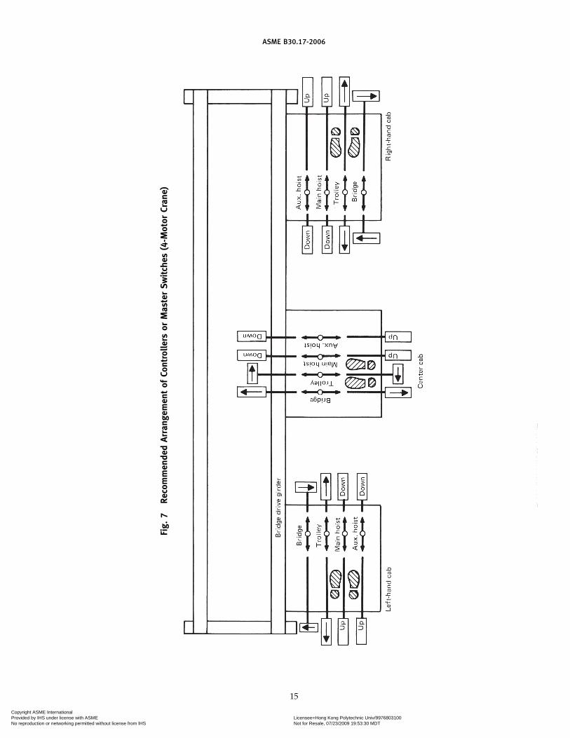
ASME B30.17-2006
Fig.
7Re
com
men
ded
Arra
ngem
ent
ofCo
ntro
llers
orM
aste
rSw
itch
es(4
-Mot
orCr
ane)
15
Copyright ASME International Provided by IHS under license with ASME Licensee=Hong Kong Polytechnic Univ/9976803100
Not for Resale, 07/23/2009 19:53:30 MDTNo reproduction or networking permitted without license from IHS
--`
``
`````
``
``
``
-`-`
``
``---

ASME B30.17-2006
Fig. 8 Recommended Arrangement of Controllers(Pendant Push-Button Station Arrangements)
GENERAL NOTE: In each user location, the relative arrangement ofunits on crane pendant push button stations should be standardized.In the absence of such standardization, arrangements 1 and 2 aboveare suggested.
16
Fig. 9 Recommended Arrangement of Controllers(Radio Crane Control Transmitter Lever Arrangements)
GENERAL NOTES:(a) Markings on the crane, visible from the floor, shall indicate the
direction of bridge and trolley travel corresponding to the W, X,Y, and Z designations on the transmitter.
(b) The letters used are only intended for the purpose ofillustration.
(c) Designations should be selected as appropriate to eachillustration.
Copyright ASME International Provided by IHS under license with ASME Licensee=Hong Kong Polytechnic Univ/9976803100
Not for Resale, 07/23/2009 19:53:30 MDTNo reproduction or networking permitted without license from IHS
--`
``
`````
``
``
``
-`-`
``
``---

ASME B30.17-2006
(d) On power-driven hoists, an overtravel limit deviceshall be provided in the lifting direction to stop hoistmotion.
(e) Hoist overtravel protection shall be in accordancewith the provisions of ASME B30.16.
17-1.13.6 Runway ConductorsConductors of the open type, mounted on the crane
runway beams or overhead, shall be so located orguarded that persons cannot inadvertently come intocontact with the energized conductors under normaloperating conditions or under maintenance proceduresas stated in para. 17-2.3.2.
17-1.13.7 Lifting Magnets(a) A crane for use with a lifting magnet shall have
a separate magnet circuit switch of the enclosed typewith provision for locking in the open (“OFF”) position.The magnet disconnect switch shall be connected on theline side (power supply side) of the crane disconnectswitch.
(b) Means shall be provided for discharging the induc-tive load of a lifting magnet.
(c) Indication or signal lights should be provided toindicate that power to a lifting magnet is on or off. Theselights, if used, shall be visible to the crane operator andto persons on the floor.
(d) For a remote-operated crane, the loss of the remotesignal shall not result in demagnetizing the liftingmagnet.
17-1.13.8 Service ReceptacleIf a service receptacle is provided in the cab or on the
bridge, it shall be a grounded-type permanent receptaclenot exceeding 300 V.
17
SECTION 17-1.14: HOISTING EQUIPMENT
Electrical and mechanical requirements for the hoistshall be in accordance with the provisions of ASMEB30.16.
SECTION 17-1.15: WARNING DEVICES FORCRANES WITH POWERTRAVELING MECHANISM
17-1.15.1 Cab- and Remote-Operated Cranes
(a) A warning device shall be provided.(b) Refer to para. 17-3.1.5(o) for operation of the
device.
17-1.15.2 Floor-Operated Cranes
(a) A warning device should be provided for installa-tions where the ability of the operator to warn personsin the path of the load is impaired.
(b) Refer to para. 17-3.1.5(o) for operation of thedevice.
17-1.15.3 Types of Devices
One or more of the following devices shall be providedwhen required:
(a) manually operated gong(b) power-operated audible signal(c) rotating beacon(d) strobe light
Copyright ASME International Provided by IHS under license with ASME Licensee=Hong Kong Polytechnic Univ/9976803100
Not for Resale, 07/23/2009 19:53:30 MDTNo reproduction or networking permitted without license from IHS
--`
``
`````
``
``
``
-`-`
``
``---

ASME B30.17-2006
Chapter 17-2Inspection, Testing, and Maintenance
SECTION 17-2.1: INSPECTION
17-2.1.1 Inspection Classification
(a) Initial Inspection. New, reinstalled, altered,repaired, and modified cranes shall be inspected priorto initial use to verify compliance with applicable provi-sions of this volume. Inspection of altered, repaired,and modified cranes may be limited to the provisionsaffected by the alteration, repair, or modification, asdetermined by a qualified person.
(b) Inspection Intervals. Inspection procedure forcranes in regular service is divided into two generalclassifications based upon the intervals at which inspec-tion should be performed. The intervals in turn aredependent upon the nature of the critical componentsof the crane and the degree of their exposure to wear,deterioration, or malfunction. The two general classifi-cations are designated as frequent and periodic, withrespective intervals between inspections as definedbelow.
(1) Frequent Inspection. Visual examinations con-ducted by the operator or other designated personnelwith records not required, as follows:
(a) normal service — monthly(b) heavy service — weekly to monthly(c) severe service — daily to weekly
(2) Periodic Inspection. Visual inspections of theequipment in place conducted by a designated personmaking records of apparent external conditions to pro-vide the basis for a continuing evaluation as follows:
(a) normal service — yearly(b) heavy service — yearly(c) severe service — quarterly
17-2.1.2 Frequent Inspection
(a) Frequent inspections shall include observationsduring operations.
(b) A designated person shall determine whether con-ditions found during the inspection constitute a hazardand a more detailed inspection is required.
(c) The following items shall be inspected:(1) operating mechanisms for proper operation,
proper adjustment, and unusual sounds(2) upper limit device(s) in accordance with ASME
B30.16(3) tanks, valves, pumps, lines, and other parts of
air or hydraulic systems for leakage
18
(4) hooks and hook latches (if used) in accordancewith ASME B30.10
(5) hoists in accordance with ASME B30.16
17-2.1.3 Periodic Inspection
(a) A designated person shall determine whether con-ditions found during inspection constitute a hazard anddisassembly is required for additional inspection.
(b) The inspection shall include the items listed inpara. 17-2.1.2(c) and the following items, as applicable:
(1) deformed, cracked, or corroded members.(2) loose or missing bolts, nuts, pins, or rivets.(3) cracked or worn sheaves and drums.(4) worn, cracked, or distorted parts such as pins,
bearings, wheels, shafts, gears, rollers, locking andclamping devices, bumpers, and stops.
(5) excessive wear of brake system parts.(6) excessive wear of drive chain sprockets and
excessive drive chain stretch.(7) deterioration of controllers, master switches,
contacts, limit switches, and push button stations, butnot limited to these items.
(8) wind indicators for proper operation.(9) gasoline, diesel, electric, or other power plants
for proper operation.(10) motion limit devices that interrupt power or
cause a warning to be activated for proper performance.Each motion shall be inched or operated at low speedinto the device with no load on the crane.
(11) controller function labels for legibility andreplacement.
(12) hoists in accordance with ASME B30.16.
17-2.1.4 Cranes Not in Regular Service
(a) A crane that is used in infrequent service, whichhas been idle for a period of one month or more, butless than 1 year, shall be inspected before being placedin service in accordance with the requirements listed inpara. 17-2.1.2.
(b) A crane that is used in infrequent service, whichhas been idle for 1 year or more, shall be inspectedbefore being placed in service in accordance with therequirements listed in para. 17-2.1.3.
17-2.1.5 Inspection Records
Dated inspection reports or comparable records shallbe made on critical items such as hoisting machinery,
Copyright ASME International Provided by IHS under license with ASME Licensee=Hong Kong Polytechnic Univ/9976803100
Not for Resale, 07/23/2009 19:53:30 MDTNo reproduction or networking permitted without license from IHS
--`
``
`````
``
``
``
-`-`
``
``---

ASME B30.17-2006
sheaves, hooks, chains, ropes, and other lifting devicesas listed in para. 17-2.1.3 and ASME B30.16. Recordsshall be placed on file.
SECTION 17-2.2: TESTING
17-2.2.1 Operational Tests
(a) New, reinstalled, altered, repaired, and modifiedcranes shall be tested by a designated person prior toinitial use to verify compliance with this Volume.
(b) Tests shall include, as applicable, the followingfunctions:
(1) lifting and lowering.(2) trolley travel.(3) bridge travel.(4) limit devices (the trip setting of hoist limit
devices shall be determined by tests with an empty hookcomprising a series of runs, each at increasing hookspeed up to a maximum speed unless the hoist has onlya single speed. The actuating mechanism of the upperlimit device shall be located or adjusted so that it willtrip the device in sufficient time to prevent contact ofthe load block or load with any part of the trolley orbridge).
(5) travel limiting devices.(6) locking and indicating devices, if provided.
(c) Operational testing of altered, repaired, and modi-fied cranes may be limited to the functions affected bythe alteration, repair, or modification, as determined bya qualified person.
17-2.2.2 Load Test
(a) New, reinstalled, altered, repaired, and modifiedcranes should be load tested by a designated personprior to initial use as determined by a qualified person. Aqualified person shall determine if a load test is required.
(b) Load testing of altered, repaired, and modifiedcranes may be limited to the functions affected by thealteration, repair, or modification, as determined by aqualified person.
(c) If a load test is conducted, the load shall be noless than 100% of the rated load of the crane or more than125% of the rated load of the crane, unless otherwiserecommended by the manufacturer or a qualifiedperson.
(d) If a load test is conducted, the person conductingthe load test shall prepare a written report of the loadsustained during the test and the operations performedduring the test. Reports shall be placed on file.
(e) If a load test is performed, operations shall beperformed as outlined below or as modified by a quali-fied person.
(1) Hoist the test load a distance to assure that theload is supported by the crane and held by the hoistbrake(s). (Hoists shall be tested under the provisions ofASME B30.16.)
19
(2) Transport the test load by means of the trolleyfor the full length of the bridge.
(3) Transport the test load by means of the bridgefor the full length of the runway in one direction withthe trolley as close to the extreme right-hand end of thecrane as practical, and in the other direction with thetrolley as close to the left-hand end of the crane as prac-tical.
(4) Lower the test load and stop and hold the testload with the brake(s).
SECTION 17-2.3: MAINTENANCE
17-2.3.1 Preventive Maintenance
(a) A preventive maintenance program should beestablished. The program should be based on the recom-mendations outlined in the crane manufacturer’s man-ual and the hoist manufacturer’s manual. If a qualifiedperson determines it is appropriate, the program shouldalso include that individual’s additional recommenda-tions based upon a review of the crane hoist applicationand operation. Dated records should be placed on file.
(b) Replacement parts shall be at least equal to theoriginal manufacturer’s specification.
17-2.3.2 Maintenance Procedure
(a) The following precautions shall be taken beforeperforming maintenance on a crane:
(1) The crane shall be moved to a location whereit will cause the least interference with other cranes andoperations in the area.
(2) If a load is attached to the crane, it shall belanded.
(3) All controllers shall be placed in the “OFF”position.
(4) A lockout/tagout procedure shall be performed(see para. 17-3.5.1).
(5) Warning signs and barriers shall be used on thefloor beneath the crane where overhead maintenancework creates a hazard.
(6) If the runway remains energized, stops or a sig-nal person(s), located full time at a visual vantage pointfor observing the approach of an active crane(s), shallbe provided to prohibit contact by the active crane(s)with the idle crane, with persons performing mainte-nance, and with equipment used in performing mainte-nance.
(7) A guard or barrier shall be installed betweenadjacent runways for the length of the established workarea to prevent contact between persons performingmaintenance and a crane on the adjacent runway.
(8) Crane travel shall be prohibited or restrictedwhile a person is on a service platform and the overheadclearance is less than 78 in. (1 980 mm) at any locationin the path of the crane.
Copyright ASME International Provided by IHS under license with ASME Licensee=Hong Kong Polytechnic Univ/9976803100
Not for Resale, 07/23/2009 19:53:30 MDTNo reproduction or networking permitted without license from IHS
--`
``
`````
``
``
``
-`-`
``
``---
ASME B30.17-2006
(b) The following precautions shall be taken beforeperforming maintenance on a crane runway, the runwaysupport structure, the runway conductor system, or theareas of the building in the path of travel of the cranebridge or trolley:
(1) A lockout/tagout procedure shall be performed(see para. 17-3.5.1).
(2) Warning signs and barriers shall be used on thefloor beneath the crane where overhead maintenancework creates a hazard.
(3) If the runway remains energized, stops or a sig-nalperson(s), located full time at a visual vantage pointfor observing the approach of an active crane(s), shallbe provided to prohibit contact by the active crane(s)with persons performing maintenance and with equip-ment used in performing maintenance.
(4) A guard or barrier shall be installed betweenadjacent runways for the length of the established workarea to prevent contact between persons performingmaintenance and a crane on the adjacent runway.
(c) Only trained and designated persons shall workon energized equipment.
(d) After maintenance work is completed and beforerestoring the crane to normal operation
(1) guards shall be reinstalled(2) safety devices shall be reactivated(3) replaced parts and loose material shall be
removed(4) maintenance equipment shall be removed
17-2.3.3 Adjustments, Repairs, and Replacements
(a) Any condition disclosed by the inspections per-formed in accordance with the requirements of Section17-2.1 that is determined to be a hazard to continuedoperation shall be corrected by adjustment, repair, orreplacement before continuing to use the crane.
(b) Adjustments, repairs, and replacements shall beperformed by designated personnel.
(c) Components shall be adjusted or repaired asneeded. The following are examples:
20
(1) all operating mechanisms(2) limit switches(3) control systems(4) brakes
(d) Repairs or replacements shall be made as needed.The following are examples:
(1) Damaged or worn hooks as described underMaintenance in ASME B30.10. Repairs by welding orreshaping are not recommended.
(2) All critical parts that are cracked, broken, bent,excessively worn, or missing.
(3) Pitted or burned electrical contacts should becorrected by replacement and in sets. Controller partsshould be lubricated as recommended in the manualsupplied with the crane.
(4) Controller function labels on pendant controlstations or master switches shall be kept legible.
(e) If repairs of load-sustaining members are madeby welding, identification of materials shall be madeand appropriate welding procedures shall be followed.
17-2.3.4 Lubrication
(a) All moving parts of the crane for which lubricationis specified should be regularly lubricated. Lubricatingsystems should be checked for delivery of lubricant.Care should be taken to follow the manufacturer’s rec-ommendations as to points and frequency of lubrication,maintenance of lubricant levels, and types of lubricantused.
(b) Machinery shall be stationary while lubricants arebeing applied, and protection shall be provided as calledfor in paras. 17-2.3.2(a)(1) through (4), unless machineryis equipped with automatic or remote lubrication.
SECTION 17-2.4: CHAIN AND ROPE INSPECTION,REPLACEMENT, ANDMAINTENANCE
Chains and ropes shall be inspected, replaced, andmaintained according to ASME B30.16.
Copyright ASME International Provided by IHS under license with ASME Licensee=Hong Kong Polytechnic Univ/9976803100
Not for Resale, 07/23/2009 19:53:30 MDTNo reproduction or networking permitted without license from IHS
` ` ` ` `` `` ` ` `` `` ` ` ` ` ` `

ASME B30.17-2006
Chapter 17-3Operation
SECTION 17-3.1: QUALIFICATIONS FOR ANDCONDUCT OF OPERATORS
17-3.1.1 Operators of Cranes
(a) Cranes shall be operated only by the followingqualified personnel:
(1) designated persons(2) trainees under the direct supervision of a desig-
nated person(3) maintenance and test personnel, when it is nec-
essary in the performance of their duties(4) inspectors (crane)
(b) No one other than personnel specified in para.17-3.1.1(a) shall enter a crane cab or pulpit, with theexception of persons such as oilers and supervisors,whose duties require them to do so, and then only inthe performance of their duties and with the knowledgeof the operator or other appointed person.
17-3.1.2 Qualifications for Operators of Cab-Operated and Pulpit-Operated Cranes
(a) Operators shall be required by the employer topass a written or oral examination and a practicaloperating examination unless they are able to furnishsatisfactory evidence of qualifications and experience.Qualification shall be limited to the specific type ofequipment for which the operator is examined.
(b) Operators and operator trainees should have nor-mal depth perception, field of vision, reaction time, man-ual dexterity, coordination, no tendencies to dizzinessor similar undesirable characteristics, and shall meet thefollowing physical qualifications:
(1) vision of at least 20/30 Snellen in one eye and20/50 in the other, with or without corrective lenses
(2) ability to distinguish colors regardless of posi-tion of colors, if color differentiation is required for theoperation
(3) adequate hearing, with or without a hearingaid, for a specific operation
(4) sufficient strength, endurance, agility, coordina-tion, and speed of reaction to meet the demands ofequipment operation
(c) Evidence of physical defects or emotional instabil-ity that could render the operator a hazard to the opera-tor or others, or that in the opinion of the examinercould interfere with the operator’s safe performance maybe cause for disqualification. In such cases, specializedclinical or medical judgments and tests may be required.
21
(d) Evidence that an operator is subject to seizuresor loss of physical control shall be reason for disqualifica-tion. Specialized medical tests may be required to deter-mine these conditions.
17-3.1.3 Qualifications for Operators of Floor-Operated Cranes
Personnel shall be required by the employer to passa practical operating examination. Qualification shall belimited to the specific type of equipment for which theoperator is examined.
17-3.1.4 Qualifications for Operators of Remote-Operated Cranes
The use of remote control equipment involves sucha wide variety of service requirements and conditionsthat each installation should be carefully analyzed andoperation reviewed at least monthly for the first 6months of operation to determine whether para. 17-3.1.2or 17-3.1.3 should apply.
17-3.1.5 Conduct of Operators
(a) The operator shall not engage in any practicethat will divert the operator’s attention while actuallyengaged in operating the crane.
(b) When physically or otherwise unfit, an operatorshall not engage in the operation of the equipment.
(c) The operator shall respond to signals from theperson who is directing the lift, or an appointed signalperson. When a signal person or a crane follower is notrequired as part of the crane operation, the operator isthen responsible for the lifts. The operator shall obey astop signal at all times, however, no matter who gives it.
(d) Each operator shall be responsible for those opera-tions under the operator’s direct control. Whenever thereis any doubt as to safety, the operator shall consult withthe supervisor before handling the loads.
(e) Before leaving the cab-operated crane unattended,the operator shall land any attached load, place control-lers or master switches in the “OFF” position, and openthe main line device of the specific crane.
(f) The operator shall not close the main disconnectdevice until certain that no worker is on or adjacent tothe crane. If there is a warning sign or lock on the device,it shall not be energized until the sign or lock is removedby either the person who placed it thereon or by anauthorized person.
Copyright ASME International Provided by IHS under license with ASME Licensee=Hong Kong Polytechnic Univ/9976803100
Not for Resale, 07/23/2009 19:53:30 MDTNo reproduction or networking permitted without license from IHS
--`
```
``
``
``
``
``
-`-`
``
``---

ASME B30.17-2006
(g) Before closing the main line disconnect of a cab-operated crane, the operator shall see to it that all con-trollers are in the “OFF” position.
(h) If power goes off during operation of acab-operated crane, the operator shall immediatelyplace all controllers or master switches in the “OFF”position. Prior to reuse of the crane, operating motionsshall be checked for proper direction.
(i) The operator shall be familiar with the equipmentand its proper care. If adjustments or repairs are neces-sary, the operator shall report the same promptly tothe appointed person who shall be responsible for theoperation and maintenance repairs of the crane. Theoperator shall also notify the next operator of anyremaining uncorrected defects upon changing shifts.
(j) Contacts with runway stops or other cranes shallbe made with caution. The operator shall do so withcare for the safety of persons on or below the cranes,and only after making certain that any persons on theother cranes are aware of what is being done.
(k) When the wind-indication device of an outdoorcrane gives the alarm, crane operation shall be discon-tinued, and the crane shall be prepared and stored forexcess wind conditions.
(l) Before the operator performs any maintenancework on the crane, the operator shall lock and tag themain switch (crane disconnect) (see para. 17-2.3.2) in thedeenergized position. If the crane is equipped with alifting magnet and the magnet is not deenergized whenthe main switch (crane disconnect) is in the deenergizedposition, the operator shall also lock and tag the magnetdisconnect switch in the deenergized position.
(m) All controls of a cab-operated crane shall betested by the operator before beginning a new shift. Ifany controls do not operate properly, they shall beadjusted or repaired before operations are begun.
(n) Persons boarding or leaving the cab of an over-head crane should do so only at authorized locationsand designated boarding entrances.
(o) The operator shall activate the warning device oncab- and remote-operated cranes, and when provided,on floor-operated cranes
(1) before starting the bridge or trolley motion ofthe crane
(2) intermittently during travel of the crane whenapproaching persons in the path of the load
SECTION 17-3.2: HANDLING THE LOAD
17-3.2.1 Load Weight
(a) The crane shall not be loaded in excess of itsrated load except for test purposes as provided in para.17-2.2.2 or for planned engineered lifts as provided inpara. 17-3.2.1.1.
(b) When multiple hoists are used for lifting a load,the combined load applied to more than one hoisting
22
unit shall not exceed the rated load of the crane.(c) When multiple hoists are used for lifting a load,
the center of gravity of the load should be determinedand the load positioned so that an individual hoist shallnot be loaded in excess of its rated load.
17-3.2.1.1 Planned Engineered Lifts. Lifts in excessof the rated load may be required from time to timeon a limited basis for specific purposes such as newconstruction or major repairs. Every planned engineeredlift exceeding the rated load shall be treated as a specialand separate event. Limitations and planned require-ments shall be applicable as follows:
(a) Planned engineered lifts are only applicable topowered cranes having a load rating of 5 tons and above.
(b) When planned engineered lifts are made, the loadshall not exceed 125% of the crane load rating exceptas provided in para. 17-3.2.1.1(d).
(c) Planned engineered lifts shall be limited to twooccurrences on any crane within any continuous12-month period, except as provided in para.17-3.2.1.1(d). If greater lift frequency is desired, consider-ation shall be given to rerating or replacing the crane.
(d) The crane manufacturer or qualified person shallbe consulted if the planned engineered lift exceeds 125%of rated load or if the frequency of planned engineeredlifts exceeds 2 during a continuous 12-month period.
(e) Each planned engineered lift shall comply withthe following requirements:
(1) A written review of the crane service historyshall be prepared, including reference to previousplanned engineered lifts, structural repairs, and modifi-cations of original design.
(2) The design of the structural, mechanical, electri-cal, pneumatic, and hydraulic components of the craneshall be reviewed by applicable calculations for the loadto be lifted and approved by the crane manufacturer ora qualified person according to accepted crane designstandards if the load to be lifted exceeds 125% of ratedload or if the frequency of planned engineered liftsexceeds 2 during a continuous 12-month period.
(3) The design of the crane supporting structureshall be reviewed and approved by a qualified personfor conformance to applicable design criteria. The cranesupport shall be inspected, and any deterioration ordamage shall be taken into consideration in design cal-culations for the load to be lifted.
(4) The crane shall be inspected in accordance withpara. 17-2.1.3 just prior to making the lift.
(5) The lift shall be made under controlled condi-tions under the direction of a designated person in accor-dance with a previously prepared lift plan. All personsin the area of the crane shall be alerted that the lift isbeing made.
(6) The operator shall test the crane at the plannedengineered load by lifting the load a short distance andsetting the brakes. The lift shall only be continued if the
(06)
Copyright ASME International Provided by IHS under license with ASME Licensee=Hong Kong Polytechnic Univ/9976803100
Not for Resale, 07/23/2009 19:53:30 MDTNo reproduction or networking permitted without license from IHS
--`
``
`````
``
``
``
-`-`
``
``---
ASME B30.17-2006
brake stops and holds the load. Any failure to hold theload shall be corrected before proceeding with the lift.
(7) The crane shall be inspected in accordance withpara. 17-2.1.3 after the lift is completed and before it isused to lift any other load.
(8) A record of the planned engineered lift, includ-ing calculations, inspections, and all distances moved,shall be placed on file for availability to appointed per-sonnel.
(f) The rated load test specified in para. 17-2.2.2 isnot applicable to planned engineered lift provisions.
17-3.2.2 Attaching the Load
(a) The hoist chain or hoist rope shall be free fromkinks or twists and shall not be wrapped around theload.
(b) The load shall be attached to the load block hookby means of slings or other devices. If slings are used,refer to ASME B30.9. If below-the-hook lifting devicesare used, refer to ASME B30.20.
(c) Care shall be taken to make certain that the load,sling, attachments, and load block clear all obstacles.
17-3.2.3 Moving the Load
(a) The appointed person directing the lift shall ascer-tain that
(1) the load, sling, or lifting device is seated in thebowl of the hook.
(2) the load is secured, balanced, and positionedin the hook, sling, or lifting device before the load islifted more than a few inches (centimeters). If slings areused, refer to ASME B30.9. If below-the-hook liftingdevices are used, refer to ASME B30.20.
(3) hoist chain or rope is not kinked.(4) multiple part lines are not twisted around
each other.(5) the hook is brought over the load in such a
manner as to minimize swinging.(6) the rope is seated in the drum grooves and in
the sheaves, if there is or has been a slack rope condition.(b) During lifting, care shall be taken that
(1) there is no sudden acceleration or decelerationof the moving load
(2) the load does not contact any obstructions(c) Cranes shall not be used for side pulls except
when specifically authorized by a qualified person whohas determined that
(1) the various parts of the crane will not be overs-tressed
(2) the stability of the crane is not endangered(3) such side pulls will not cause the hoist rope to
be pulled out of the sheaves or across drum grooves(4) such side pulls will not result in excessive
swinging of the load block or load
23
(d) The operator shall not cause the crane to lift,lower, or travel while anyone is on the load or hook.
(e) The operator should avoid carrying loads overpeople.
(f) The operator of a floor-operated crane having alifting magnet should exercise caution due to the hazardof possible falling metal.
(g) The operator shall check the hoist brake(s) at leastonce each shift if a load approaching the rated load isto be handled. This shall be done by lifting the load ashort distance and applying the brake(s).
(h) The load shall not be lowered below the pointwhere two wraps of rope remain on each anchorage ofthe hoisting drum unless a lower limit device is pro-vided, in which case no less than one wrap shall remain.
(i) When two or more cranes are used to lift a load,one qualified person shall be in charge of the operation.This person shall analyze the operation and instructother personnel involved in the proper positioning, rig-ging of the load, and the movements to be made.
(j) The operator shall not leave the position at thecontrols while the load is suspended over an area accessi-ble to people.
17-3.2.4 Parking the Load
(a) The operator should not leave a suspended loadunattended unless specific precautions have been insti-tuted and are in place.
(b) The load block should be lifted above head levelfor storage when the crane is not in use.
17-3.2.5 Hoist Limit Device (Switches)
The hoist limit device that controls the upper limit oftravel of the load block shall not be used as an operatingcontrol in normal operation unless additional means areprovided to prevent damage from overtravel.
SECTION 17-3.3: SIGNALS
17-3.3.1 Standard Signals
(a) Signals to the operator shall be in accordance withthis volume, unless voice communication (i.e., tele-phone, radio, or equivalent) is used.
(b) Signals should be discernible or audible to theoperator.
(c) Hand signals shall be posted conspicuously andshould be as illustrated in Fig. 10.
17-3.3.2 Special Signals
(a) Special operations may require additions to ormodifications of standard signals.
(b) Special signals shall be agreed upon and under-stood by the signal person and the operator.
(c) Special signals shall not conflict with standardsignals.
Copyright ASME International Provided by IHS under license with ASME Licensee=Hong Kong Polytechnic Univ/9976803100
Not for Resale, 07/23/2009 19:53:30 MDTNo reproduction or networking permitted without license from IHS
--`
```
``
```
```
``-`-`
```
`---

ASME B30.17-2006
Fig. 10 Standard Hand Signals for Controlling Single-Girder Top Running Cranes
24
Copyright ASME International Provided by IHS under license with ASME Licensee=Hong Kong Polytechnic Univ/9976803100
Not for Resale, 07/23/2009 19:53:30 MDTNo reproduction or networking permitted without license from IHS
--`
``
`````
``
``
``
-`-`
``
``---

ASME B30.17-2006
SECTION 17-3.4: MISCELLANEOUS
17-3.4.1 Ladders
(a) Hands shall be free from encumbrances whilepersonnel are using ladders.
(b) Articles that are too large to be carried in pocketsor tool belts shall be lifted and lowered by hand line.
17-3.4.2 Cabs
(a) Necessary clothing and personal belongings shallbe stored in a manner that does not interfere with accessor operation.
(b) Tools, oil cans, rags, and other necessary articlesshall be stored in a fire-resistant container and shall notbe permitted to lie loose in or about the cab.
17-3.4.3 Fire Extinguishers
Operators shall be familiar with the location, opera-tion, and care of fire extinguishers provided (see para.17-1.5.5).
25
SECTION 17-3.5: CRANE LOCKOUT/TAGOUT
(a) A lockout/tagout policy and procedure shall bedeveloped, documented, and implemented by theowner or user of overhead cranes.
(b) The lockout/tagout policy and procedure shallcomply with the requirements of ANSI Z244.1.
(c) The policy shall give consideration to the fol-lowing:
(1) single crane runways(2) multiple crane runways(3) cranes on an adjacent runway(4) runway disconnecting means(5) crane disconnecting means(6) work to be done on a crane(7) work to be done other than on a crane but
within the path of a crane where its movement createsa hazard
Copyright ASME International Provided by IHS under license with ASME Licensee=Hong Kong Polytechnic Univ/9976803100
Not for Resale, 07/23/2009 19:53:30 MDTNo reproduction or networking permitted without license from IHS
--`
``
`````
``
````
-`-`
```
`---

26
Copyright ASME International Provided by IHS under license with ASME Licensee=Hong Kong Polytechnic Univ/9976803100
Not for Resale, 07/23/2009 19:53:30 MDTNo reproduction or networking permitted without license from IHS
--`
```
`````
`````-`-`
``
``---

ASME Services
ASME is committed to developing and delivering technical information. At ASME’s Information Central, we make every effort to answer yourquestions and expedite your orders. Our representatives are ready to assist you in the following areas:
ASME Press Member Services & Benefits Public InformationCodes & Standards Other ASME Programs Self-Study CoursesCredit Card Orders Payment Inquiries Shipping InformationIMechE Publications Professional Development Subscriptions/Journals/MagazinesMeetings & Conferences Short Courses Symposia VolumesMember Dues Status Publications Technical Papers
How can you reach us? It’s easier than ever!
There are four options for making inquiries* or placing orders. Simply mail, phone, fax, or E-mail us and an InformationCentral representative will handle your request.
Mail Call Toll Free Fax—24 hours E-Mail—24 hoursASME US & Canada: 800-THE-ASME 973-882-1717 [email protected] Law Drive, Box 2900 (800-843-2763) 973-882-5155Fairfield, New Jersey Mexico: 95-800-THE-ASME07007-2900 (95-800-843-2763)
Universal: 973-882-1167
* Information Central staff are not permitted to answer inquiries about the technical content of this code or standard. Information as towhether or not technical inquiries are issued to this code or standard is shown on the copyright page. All technical inquiries must besubmitted in writing to the staff secretary. Additional procedures for inquiries may be listed within.
Copyright ASME International Provided by IHS under license with ASME Licensee=Hong Kong Polytechnic Univ/9976803100
Not for Resale, 07/23/2009 19:53:30 MDTNo reproduction or networking permitted without license from IHS
--`
``
`````
``
``
``
-`-`
``
``---

Copyright ASME International Provided by IHS under license with ASME Licensee=Hong Kong Polytechnic Univ/9976803100
Not for Resale, 07/23/2009 19:53:30 MDTNo reproduction or networking permitted without license from IHS
--`
```
``
```
```
``-`-`
```
`---

J06006
ASME B30.17-2006
Copyright ASME International Provided by IHS under license with ASME Licensee=Hong Kong Polytechnic Univ/9976803100
Not for Resale, 07/23/2009 19:53:30 MDTNo reproduction or networking permitted without license from IHS
--`
``
`````
``
``
``
-`-`
```
`---