Overcoming Object-Relational Impedance Mismatch in … · Overcoming the Object-Relational...
14
Wieckowicz, Alison. 2010. Overcoming the Object-Relational Impedance Mismatch in GIS Development: a Comparison of Data Abstraction and Serialization Methods used in Web Mapping Application Development. Volume 12. Papers in Resource Analysis. 14 pages. Saint Mary’s University of Minnesota University Central Service Press. Winona, MN. Retrieved (date) http://www.gis.smumn.edu Overcoming Object-Relational Impedance Mismatch in GIS Development: a Comparison of Data Abstraction and Serialization Methods used in Web Mapping Application Development Alison Wieckowicz Department of Resource Analysis, Saint Mary’s University of Minnesota, Minneapolis, MN 55404 Keywords: Geodatabase, Object-Relational Impedance Mismatch, Object-Relational Mapping, Entity Modeling, N-Tier Architecture Abstract This paper presents two data access strategies that employ different data abstraction and serialization methods applied to a working geodatabase to facilitate development of a web mapping application. The goal of the study was to compare methods used to minimize the effects of object-relational impedance mismatch, a well-known set of issues that result from the integration of relational data and object-oriented programming languages. This study focused specifically on increasing support for schema evolution; a common object-relational impedance issue within GIS systems. The study was conducted using a real-life, transactional geodatabase used to maintain water quality data. The database and test applications were designed to meet real-life functional requirements. The first method employed the use of entity modeling techniques in the application mid-tier to map relational geospatial data from the relational database management system to an object-oriented model in order to facilitate data access, serialization and transport via a web service; the second procedure maintained application logic within the object-relational geodatabase system tables and employed a generic abstraction method for serialization within a web service. The resulting n-tier applications were tested by applying a unit test strategy based on real-life use case scenarios and the results were compared to assess the extensibility, maintainability and richness of the result. The application that leveraged the object-relational model of the geodatabase system was found to provide better support for schema changes to the geodatabase resulting in less maintenance, while the application constructed using entity modeling of relational data resulted in richer UI features but was not able to support schema changes to the geodatabase. Introduction Relational databases are a widespread storage format for geospatial data. Commonly used development frameworks for web mapping solutions are designed for object-oriented development. A well-known set of problems, commonly referred to as object-relational impedance mismatch, occur when applications are developed using object-oriented concepts to access data persisted in relational databases. Due to the increasingly widespread implementation of service-oriented (SOA), multi-tier (also
-
Upload
nguyenduong -
Category
Documents
-
view
244 -
download
0
Transcript of Overcoming Object-Relational Impedance Mismatch in … · Overcoming the Object-Relational...

Wieckowicz, Alison. 2010. Overcoming the Object-Relational Impedance Mismatch in GIS Development: a
Comparison of Data Abstraction and Serialization Methods used in Web Mapping Application Development.
Volume 12. Papers in Resource Analysis. 14 pages. Saint Mary’s University of Minnesota University Central
Service Press. Winona, MN. Retrieved (date) http://www.gis.smumn.edu
Overcoming Object-Relational Impedance Mismatch in GIS Development: a Comparison
of Data Abstraction and Serialization Methods used in Web Mapping Application
Development
Alison Wieckowicz
Department of Resource Analysis, Saint Mary’s University of Minnesota, Minneapolis, MN
55404
Keywords: Geodatabase, Object-Relational Impedance Mismatch, Object-Relational Mapping,
Entity Modeling, N-Tier Architecture
Abstract
This paper presents two data access strategies that employ different data abstraction and
serialization methods applied to a working geodatabase to facilitate development of a web
mapping application. The goal of the study was to compare methods used to minimize the effects
of object-relational impedance mismatch, a well-known set of issues that result from the
integration of relational data and object-oriented programming languages. This study focused
specifically on increasing support for schema evolution; a common object-relational impedance
issue within GIS systems. The study was conducted using a real-life, transactional geodatabase
used to maintain water quality data. The database and test applications were designed to meet
real-life functional requirements. The first method employed the use of entity modeling
techniques in the application mid-tier to map relational geospatial data from the relational
database management system to an object-oriented model in order to facilitate data access,
serialization and transport via a web service; the second procedure maintained application logic
within the object-relational geodatabase system tables and employed a generic abstraction
method for serialization within a web service. The resulting n-tier applications were tested by
applying a unit test strategy based on real-life use case scenarios and the results were compared
to assess the extensibility, maintainability and richness of the result. The application that
leveraged the object-relational model of the geodatabase system was found to provide better
support for schema changes to the geodatabase resulting in less maintenance, while the
application constructed using entity modeling of relational data resulted in richer UI features but
was not able to support schema changes to the geodatabase.
Introduction
Relational databases are a widespread
storage format for geospatial data.
Commonly used development frameworks
for web mapping solutions are designed for
object-oriented development. A well-known
set of problems, commonly referred to as
object-relational impedance mismatch,
occur when applications are developed using
object-oriented concepts to access data
persisted in relational databases. Due to the
increasingly widespread implementation of
service-oriented (SOA), multi-tier (also

2
known as n-tier) architecture there is an
increased need to improve the
interoperability, and extensibility of data
access services. This need is also present
within GIS application development where
data services are often used to provide
access to relational schema that undergo
periodic database refactoring as geodatabase
schema evolve over time.
According to Ambler (1998), object-
relational impedance mismatch is defined as
follows: “The difference resulting from the
fact that relational theory is based on
relationships between tuples (records) that
are queried, whereas the object paradigm is
based on relationships between objects that
are traversed”. Interoperability of these
systems is often achieved through the
implementation of object-relational mapping
(ORM). ORM is the process of mapping
objects to relational data in order to
overcome the impedance mismatch. N-tier
applications are applications where
presentation, service, business logic and data
tiers are logically and sometimes physically
separate. In n-tier applications the ORM
process occurs within the mid-tier, between
the data and service tiers. This often results
in common language runtime (CLR) objects.
Relational data are abstracted into objects
that integrate easily with popular object-
oriented languages. The purpose of entity
modeling within this process is to project
data from a logical relational model to an
object-oriented language. This results in
compiled, object-relational mappings that
can be queried and manipulated using
object-oriented languages, often from
multiple application tiers.
Entity modeling is a form of ORM
that raises the level of abstraction within the
mid-tier. In an entity data model (EDM),
entities and associations can be used to
represent conceptual, as opposed to
relational, models as they are abstracted into
objects. Entities represent top-level objects,
for example a row or a tuple, with identities,
while associations are used to relate two or
more entities (Adya, A., et al., 2007). In n-
tier development the objects that result from
EDM provide better multi-tier access since
these objects can be serialized using an
interchange format such as XML or JSON
for web service invocation and desterilized
within the presentation (client) tier as
needed. The study described in this paper
uses an Entity Data Model (EDM) as a
means of object-relational mapping.
Unfortunately, ORM/EDM does not
entirely overcome the impedance mismatch
problem. Although EDM frameworks like
the Microsoft ADO.NET Entity Framework,
were designed to reduce object-relation
impedance mismatch as it relates to code
semantics and inefficiencies (Adya, et al.,
2007), some definitions of object-relational
impedance mismatch identify ORM/EDM as
a cause of impedance mismatch, rather than
a solution (Chen and Huang, 1995);
especially when mappings between objects
and tables are made in a very
straightforward way (Wikipedia, 2010).
This is because when the relational schema
changes, which can be quite common in
transactional GIS systems, the relational
model and the object model become
inconsistent and the mapping between the
two models must be updated to maintain
synchronization. In an application with
ORM CLR objects, synchronization would
require code changes and recompilation of
the ORM assemblies. Although, methods
have been proposed for maintaining the
consistency of these mappings under
database evolution (An, et al., 2008), these
methods are quite complex and difficult to
implement without an existing framework in
place.
One alternative to ORM is to employ
an Object-Relational Database Management

3
System (ORDBMS). ESRI’s geodatabase is
an ORDBMS. It essentially consists of a
RDBMS core with an object-oriented shell
or layer through which applications access
and manage persistent data. The object-
oriented model within the RDBMS consists
of a series of relational tables, referred to as
the Geodatabase System Tables, which hold
data used to instantiate objects. Metadata for
all objects within a geodatabase, for
example feature classes, tables and
relationships classes, is persisted in the
Geodatabase System Tables. Relational GIS
data is stored within the RDBMS within a
set of business tables. In ORDBMS, object-
oriented programming concepts such as
polymorphism and inheritance result in
advantages for application developers and
tend to minimize object-relational
impedance mismatch (Worboys and
Duckham, 2004).
One way ORDMSs reduce
impedance mismatch is by increasing
support for schema evolution. A common
feature of object-oriented systems is schema
management including the ability to create
and change class schemes (Worboys and
Duckham, 2004). This feature is part of
ESRI’s Geodatabase System as well. It is
apparent in the ability of GIS practitioners to
administer schema changes using ArcGIS
data management tools. Typical ESRI
Geodatabase client applications like ArcMap
are able to support schema changes to
underlying databases due to the object-
relational model employed by the system.
Consider the example of relationships
between spatial features. These
relationships are defined within the
geodatabase as a relationship class object.
In this way new relationships can be defined
at any time. GIS client applications are built
using ArcObjects to interface with the
objects defined within the GDB System
Tables. As a component of the object-
relational GIS system, they are able to
support schema changes and evolve as the
underlying geodatabase changes without the
need for code maintenance.
Although ArcObjects are a viable
and supported solution to the issues of
impedance mismatch, third party
Applications Programming Interface (API)
dependence is an issue for several reasons.
The ArcGIS Server Web APIs that have
been developed to work with the ESRI GIS
systems have limited access to fine-grained
ArcObjects within the service, and
presentation tier of n-tier technology such as
Silverlight. It is also documented that
application performance is adversely
affected by frequent calls to fine-grained
ArcObjects (Laframbiose, 2006; Flood,
2002). In addition, Silverlight was
developed to mesh seamlessly with
ADO.NET Entity Framework, a robust
EDM solution, as well as SOA frameworks,
making an ArcObjects-free solution
appealing. For these reasons, there is a
need to investigate alternate solutions that
overcome the object-relational impedance
mismatch without heavy reliance on
proprietary APIs.
Some strategies for minimizing
impedance mismatch leverage RDBMS
programming languages such a Transact-
SQL (TSQL). As Zdonik and Maier (1990)
point out: “a loss of information occurs at
the interface, if the programming language
is unable to represent database structures,
such as relationships, directly.” This is
essentially what happens when the objects
and the relational model, joined by an ORM,
become out-of-sync due to schema changes
to the relational model. Zdonik and Maier
(1990) imply that impedance mismatch is
proportional to the amount of interface that
occurs between the relational and object-
oriented components of the application,
therefore, maintaining more of the

4
application within one system would lower
impedance mismatch. Although not entirely
computationally complete when compared
to an object-oriented language, stored
procedures and TSQL come very close.
Implementing stored procedures that
navigate the ArcSDE System Tables to
provide access to objects would likely
overcome many of the impedance mismatch
problems that occur within GIS systems and
result in a solution that can support schema
changes.
In addition to leveraging RDBMS
languages such as TSQL to reduce
impedance mismatch, others have suggested
using loosely-typed object mappings to
increase “data independence” within
systems (Bernstein, et al., 2008). This
differs from typical EDM strategies where
relational schema is mapped to strongly-
typed CLR objects. This concept could be
implemented within the mid-tier of the
application as a way of exposing data to
client applications via web services without
creating hard-coded objects that are
dependent on explicit data structures. The
result would be more capable of supporting
schema changes.
Data
Water Quality Database
Several years’ worth of water quality data
has been collected by specialists within the
city of Eagan, Minnesota and has resulted in
a robust geodatabase that is primarily
maintained and developed by water quality
staff with knowledge of ArcGIS and
Geodatabase schema management
techniques. The database consists mainly of
water body feature classes; lakes, wetlands,
and storm basins, and related water quality
data stored within stand alone tables.
Relationship classes are defined to relate the
water body features to the standalone tables,
typically in a one-to-many specificity.
Attribute domains are used where ever
possible to maintain the integrity of the
tabular data.
The Water Quality geodatabase runs
on ArcSDE 9.3.1 and Microsoft SQL Server
2008. A geodatabase data model diagram of
the water quality database is displayed in
Appendix 3.
Methods
Application Development Objectives
There were two primary objectives
considered when developing the study
applications. As stated earlier, the first
objective was to maintain the level of
schema management afforded by ArcGIS,
while minimizing or eliminating the need for
code or relational mapping maintenance and
application recompiles. The second was to
improve the end user experience for users
who have limited GIS knowledge and who
would primarily be viewing data related in a
one-to-many cardinality to water body
features in the Geodatabase. In addition,
typical web mapping application
development objectives were upheld.
Limitations
Since the intent of the case study application
was to provide an interface for internal
employees to access the water quality
database and not individuals from the
general public, security was not a
consideration during the development of the
services or application.
Additionally, the geodatabase
versioning workflow used by staff to
maintain the water quality data was
simplistic and implemented the option to
move edits to base tables. For this reason,

5
there was no need to consider more complex
versioning scenarios within this study.
Development Methods
Both study applications used in this
comparison were developed using C# and
Microsoft .NET 4.0 within the Microsoft
Visual Studio 2010 Environment. The .NET
framework was selected as the platform for
development for several reasons. Mainly,
the .NET framework includes well
documented and easily integrated
frameworks for developing each tier of the
study application including EDM, web data
service development (Klein, 2010), as well
as client interface development and
automated unit testing (Ghoda, 2010).
The presentation layer, a portion of
client-tier, for both study applications was
developed using consistent methods. Both
client-tier applications were developed using
Microsoft Silverlight version 4.0. The
client-tier consists of a map-centric user
interface (UI) constructed using the ArcGIS
Server API for Microsoft Silverlight 2.0. A
simple ArcGIS Server web mapping service
was used to publish the water body features
(lakes, storm basins and wetlands) as a
single service. The service was consumed
within the ArcGIS Server Silverlight map
control. Both applications included
traditional GIS “identify” functionality.
The interface also contained a Silverlight tab
control designed to display a series of data
grids that hold records related to the water
body features. The data grids were
populated with related records based on the
results of an identify event.
Application 1
Application 1 employed a data access
strategy that was developed using an entity
model in the mid-tier to map data from the
business tables of the waters geodatabase to
data objects used within the application.
Figure 1 depicts Application 1 as an n-tier
application with an Entity model represented
within the mid tier and client tiers.
The EDM of the water quality
geodatabase was designed using Microsoft
ADO.NET Entity Framework data modeling
tools. The water quality database feature
classes, tables and relationship classes were
redefined within the entity model context.
Figure 1. Application 1 n-tier diagram.

6
Associations between feature class business
tables and standalone tables were defined
based on the characteristics of existing
relationship classes within the geodatabase.
The cardinality of each relationship was
defined within the multiplicity property of
the association. Appendix 1 illustrates the
structure of the lakes entity object.
Wetlands and storm basin entity types were
created using similar methods.
This process resulted in a series of
.NET classes that defined strongly-typed
objects known as entity types. Each entity
type mapped a feature class to its associated
tables. Data in the tables was accessed
through properties and methods of the entity
type.
A type of Windows Communication
Service (WCF) web service, specifically a
Domain Service, was used to expose the
entity model. WCF Data Services expose
data, often represented as EDM entity
objects, via web services accessed over
HTTP. In addition to exposing data over
HTTP, WCF Domain Services manage the
serialization of data objects between the
server-side (mid-tier) and the client-tier.
The Domain Service that was implemented
within Application 1 enabled the query of
EDM types via domain context objects.
Context objects could be considered a
“mirror image” of the EDM objects on the
client. The resulting server-side and client-
side classes enabled the query of data via
strongly-typed CLR object instances of the
entity types from multiple application tiers.
Application logic was added to the
domain service class so that data operations
could be exposed through the service.
Since the backend geodatabase included
aliased fields, business logic was added to
the client tier to accommodate functionality
within the EDM Domain Data Service
context.
Application 2
Application 2 was designed to demonstrate
the use of TSQL and generic data services to
eliminate object-relational impedance
mismatch within the application. Rather
than creating mapping between the business
tables within the relational geodatabase and
an object-oriented language, in Application
2 objects were accessed by querying the
geodatabase system tables using TSQL.
Since ArcObjects were not readily available
for development within the web tier of the
application, an equivalent set of objects
needed to be developed to provide access to
the data within the object-relational model.
This was accomplished using a custom data
access layer that navigated the relationships
defined within the geodatabase system
tables and acted as a means of interfacing
with the objects stored within.
Figure 2 shows the n-tier application logic
developed within Application 2.
The business logic within
Application 2 resides within the database as
a pair of stored procedures that query the
geodatabase system tables that hold objects
defining relationship classes, tables and field
information. Figure 3 depicts the structure
of GDB systems tables queried within the
custom stored procedures.
The first stored procedure accepts a
layer name as a parameter and returns a list
of relationship class names where the
identified layer is the origin object class.
The second stored procedure accepts the
object ID of a spatial feature and the name
of a relationship class object, for example
“Lakes_has_Inspections” and returns a table
of related values. The stored procedures are
designed to be called through a web services
by the client-tier. Table 1 describes input
parameters and results of each stored
procedure._____________________

7
Figure 2. Application 2 n-tier diagram.
Figure 3. Geodatabase system tables used by
Application 2.
The application logic within the
client-tier of Application 2 was designed to
query the first stored procedure to get a list
of relationship classes related to the
identified feature and then used the resulting
list to recursively query the second stored
procedure to retrieve tables of records
related to the feature.
Table 1. Stored procedure inputs and results.
The data access layer consists of a
WCF service with a very simple generic
operation contract, “GetData”, through
which the stored procedures are queried by
the client-tier. This is accomplished by
making a call to the stored procedure, and
then casting the results to an anonymous
.NET IEnumerable object. Generally
speaking, an IEnumerable object consists of
a collection of collections. In this case each
enumerable consists of a set of key-value
pairs; fieldname, field value. The
enumerable object is then serialized for
transport to the client-tier. The code in
listing 1 shows a portion of the operation
contract for the service. The GetData
methods accept a query parameter which
contains a query used to execute one of the
stored procedures.
Listing 1. Code sample from the operation contract
of the web service used in Application 2.
namespace Application2 { [ServiceContract(Namespace = "")]
Stored
Procedure
Input Parameters Result
ListRelates Featureclass name A table containing a row for each relationship with
a single column; RELATIONSHIPNAME
QueryRelated Relationship class name
ObjectID
Anonymous table of
related results.

8
public class MyService { [OperationContract] public IEnumerable<Dictionary<string, object>> GetData(string query) { var table = GetDataTable(query); var columns = table.Columns.Cast<DataColumn>(); return table.AsEnumerable().Select(r => columns.Select(c => new { Column = c.ColumnName, Value = r[c] }) .ToDictionary(i => i.Column, i => i.Value != DBNull.Value ? i.Value : null)) }
On the client-tier, a custom class was
included to iterate the enumerable objects
returned by the service in order to recreate a
datatable from it. The resulting datatable
object is used within the user interface
application logic. If the request sends a
query string to query the second stored
procedure for related records based on a
relationship class, the result will be bound to
a Silverlight data grid control.
Analysis Methods
Both applications were tested by
implementing a set of real-life use case
scenarios, designed to uphold development
objectives. The performance and code
maintenance requirements of the two study
applications were assessed by implementing
an automated black-box type testing created
using the Microsoft Silverlight Unit Testing
Framework.
Use Case Scenario
Both applications were tested based on a
typical use case scenario modeled in figure
4, which was designed to verify that the
functional requirements and development
objectives were met.
Figure 4. Use case model depicting primary actors
within a GIS system and tasks performed.
The use case diagram shown in
figure four illustrates the actors and the tasks
that each actor would carry out within the
GIS system. Table 2 details what
applications were to be used by each actor to
carry out GIS tasks displayed in the model.
Both of the study applications were intended
for use by water quality staff to query data
while the ArcGIS desktop applications were
used to perform other GIS tasks like schema
management.
In conversational form, a typical use
case outline for either of the study
applications would occur as follows:
Actor 1 (a water quality staff
member) runs the application from a
known URL and is presented with a
map displaying the spatial locations
of water body features within the
city.
Actor 1 navigates the map using
typical web map navigation key
clicks and identifies a water body
feature of interest.
Actor 1 uses the cursor to click on a
water body feature and is presented
with data within a tab control. Each
Water
Quality Staff
Water Quality
Specialist
GIS Admin
view records
related to spatial
features
insert, update
and delete
spatial data
modify
geodatabase
schema
9
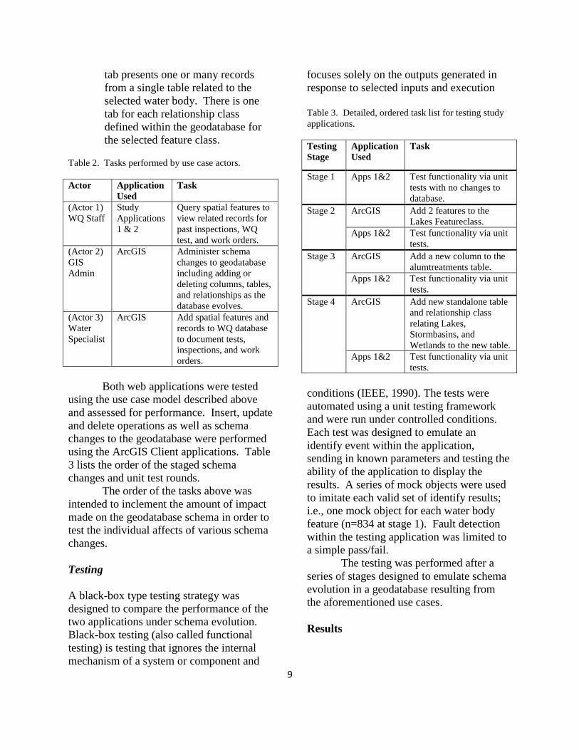
tab presents one or many records
from a single table related to the
selected water body. There is one
tab for each relationship class
defined within the geodatabase for
the selected feature class.
Table 2. Tasks performed by use case actors.
Actor Application
Used
Task
(Actor 1)
WQ Staff
Study
Applications
1 & 2
Query spatial features to
view related records for
past inspections, WQ
test, and work orders.
(Actor 2)
GIS
Admin
ArcGIS Administer schema
changes to geodatabase
including adding or
deleting columns, tables,
and relationships as the
database evolves.
(Actor 3)
Water
Specialist
ArcGIS Add spatial features and
records to WQ database
to document tests,
inspections, and work
orders.
Both web applications were tested
using the use case model described above
and assessed for performance. Insert, update
and delete operations as well as schema
changes to the geodatabase were performed
using the ArcGIS Client applications. Table
3 lists the order of the staged schema
changes and unit test rounds.
The order of the tasks above was
intended to inclement the amount of impact
made on the geodatabase schema in order to
test the individual affects of various schema
changes.
Testing
A black-box type testing strategy was
designed to compare the performance of the
two applications under schema evolution.
Black-box testing (also called functional
testing) is testing that ignores the internal
mechanism of a system or component and
focuses solely on the outputs generated in
response to selected inputs and execution
Table 3. Detailed, ordered task list for testing study
applications.
Testing
Stage
Application
Used
Task
Stage 1 Apps 1&2 Test functionality via unit
tests with no changes to
database.
Stage 2 ArcGIS Add 2 features to the
Lakes Featureclass.
Apps 1&2 Test functionality via unit
tests.
Stage 3 ArcGIS Add a new column to the
alumtreatments table.
Apps 1&2 Test functionality via unit
tests.
Stage 4 ArcGIS Add new standalone table
and relationship class
relating Lakes,
Stormbasins, and
Wetlands to the new table.
Apps 1&2 Test functionality via unit
tests.
conditions (IEEE, 1990). The tests were
automated using a unit testing framework
and were run under controlled conditions.
Each test was designed to emulate an
identify event within the application,
sending in known parameters and testing the
ability of the application to display the
results. A series of mock objects were used
to imitate each valid set of identify results;
i.e., one mock object for each water body
feature (n=834 at stage 1). Fault detection
within the testing application was limited to
a simple pass/fail.
The testing was performed after a
series of stages designed to emulate schema
evolution in a geodatabase resulting from
the aforementioned use cases.
Results

10
Tables 4 through 7 show the results of the
automated tests for each of the study
applications during each stage of the testing.
Table 4. Unit testing results for stage 1.
Application Pass/Fail Average Time to
Execute (µs)
Application 1 834/0 38275
Application 2 834/0 23881
Table 5. Unit testing results for stage 2.
Application Pass/Fail Average Time to
Execute (µs)
Application 1 836/0 37568
Application 2 836/0 24227
Table 6. Unit testing results for stage 3.
Application Pass/Fail Average Time to
Execute (µs) Application 1 809/27 37986
Application 2 836/0 24992
Table 7. Unit testing results for stage 4.
Application Pass/Fail Average Time to
Execute (µs) Application 1 0/836 36487
Application 2 836/0 23129
Both applications performed well during
stage 1 and 2. Both passed 100% of tests
run against 834 (stage 1) and 836 (stage 2)
mock objects. During stage 3, Application 1
failed 27 of 836 tests while Application 2
passed all tests.
The average executing time is
indicative of execution under “best-case”
circumstances since the client application
and service were all running on the same
workstation, eliminating network factors.
The difference in execution times between
tests run against Application 1 and
Application 2 was not large and so,
generally speaking, was similar between the
two applications.
Discussion
Test Results
The 27 failed tests that occurred after the
insertion of a new column in the alum
treatments table likely occurred because 27
water body features had related alum
treatment records and none of the alum
treatment query results reflected the changes
to the underlying data table. This is an
indication that the object-relational mapping
of the EDM is out of sync with the relational
data structure. The number of tests failed by
Application 1 increased in stage 4 because
the addition of a new table and relationship
classes had a larger impact within the
database; affecting more features.
Throughout the testing Application 2
continued to perform well. Changes made
to the schema of the relational geodatabase
were reflected in the query results displayed
within the application. Application 2 was
made “aware” of these changes in the same
way that an ArcGIS desktop application
does, by querying objects stored in the GDB
system tables.
Considerations
Some features common to both applications
enhanced their ability to accommodate
schema changes. One important feature of
Silverlight is the ability to auto-generate
columns when binding data to a data grid.
Doing so reduces the level of dependence
the application code has on the data
structure since no column names were
referenced within the code.
Although the unit testing results
indicated that Application 1 failed several
tests due to schema changes to the
underlying database, it is relevant to discuss
the definition of a failed test within this
study. The testing strategy used within this

11
application was designed to fail if a test
result did not reflect accurate results based
on the underlying geodatabase design. This
is noteworthy because in traditional
development terms the application may not
have actually thrown an exception in all
cases. Due to the way that the EDM model
was used to query the database, an exception
may not have been thrown if a column was
added to a table that was abstracted within
the entity, since the entity type doesn’t
possess a property that maps to the column.
Additional ad hoc testing indicated that an
exception would be thrown only if a column
or table that was mapped to an existing
entity property was deleted. In this way, the
EDM approach to data access may be a good
fit for some GIS systems needing to improve
the level of support for schema changes.
However, this does not provide the level of
support for schema changes needed to meet
the development objectives of this study.
Although Application 2 proved
better able to support schema changes, the
strongly-typed data mapping features of the
EDM used in Application 1 are noteworthy.
The data features of EDM and Silverlight
make it easier to incorporate rich UI features
like better data validation on the client-tier.
For example, prebuilt Silverlight controls,
like the calendar control, depend on
explicitly defined field types like date fields.
This level of data validation was not easily
incorporated within Application 2 due to the
generic nature of the data objects.
There were also some notable
disadvantages to leveraging the geodatabase
system tables that became evident in the
development of Application 2. The issues
encountered were primarily caused by the
complexity of the geodatabase system. One
example of this is apparent when examining
the graphic in Appendix 2, which shows a
display of the completed water quality
application (Application 2). Note that there
is a tab in the tab control and table populated
with related data based on a relationship
class used to facilitate feature-linked
annotation. This was not a desirable
outcome. Additional logic would need to be
added to the stored procedures to exclude
this type of relationship.
Conclusion
Leveraging the ESRI object-relational
geodatabase model in GIS application
development can provide a means of
accommodating schema evolution that
commonly occurs within a GIS system.
Stored procedures and TSQL have proven to
be an efficient method for querying the
geodatabase system tables while minimizing
the amount of impedance mismatch within
the object-oriented code. The explicit
configuration used within EDM results in
greater dependence on the underlying
relational data structure and additional code
maintenance is needed to support schema
changes.
Acknowledgments
I would like to sincerely thank the City of
Eagan, MN Water Quality and GIS staff,
namely Tami Maddio, Leah Sperduto and
Jesse Koehle for identifying the needs
addressed within this study as well as for
providing support throughout the
development process. In addition to sharing
their knowledge of water quality data and
workflows, they also contributed input for
use-case modeling, needs assessment,
application design and development. I
would also like to extend thanks to the GIS
staff at St. Mary’s University of Minnesota
Department of Resource Analysis for their
assistance with this project, especially, Mr.
Patrick Thorsell for his assistance with
evaluating and formatting the
documentation.

12
References
Adya, A., Blakeley, J.A., Melnik, S.,
Muralidhar, S., and the ADO.NET
Team. 2007. Anatomy of the ADO.NET
Entity Framework. ACM SIGMOD Int.
Conf. on Management of Data
(SIGMOD’07), June 12–14, 2007,
Beijing, China. Retrieved on March 20,
2010 from http://citeseerx.ist.psu.edu/
viewdoc/download?doi=10.1.1.148.
1125&rep=rep1&type=pdf.
Ambler, S.W. 1998. Process Patterns:
Building Large-Scale Systems Using
Object Technology. New York: SIGS
Books/Cambridge University Press.
An, Y., Hu, x., and Song, I. 2008. Round-
Trip Engineering for Maintaining
Conceptual-Relational Mapping.
Advanced Information Systems
Engineering Lecture Notes in Computer
Science, Volume 5074/2008, 296-311,
DOI: 10.1007/978-3-540-69534-9_24.
Berstein, A., Sergey, M., and Terwillinger,
J.F. 2008. Language-Integrated
Querying of XML Data in SQL Server.
Proceeding of the Very Large Database
Endowment 2008. 1, 1, 1396-1399.
Retrieved on June 6, 2010 from
http://www.vldb.org/pvldb/1/
1454182.pdf.
Chen, J. and Huang, Q. 1995. Eliminating
the Impedance Mismatch Between
Relational Systems and Object-Oriented
Programming Languages. In Proceedings
of the 6th International Hong Kong
Database Workshop.
Flood, B., 2002. Building GIS Web
Services With .NET and ArcObjects. In
Proceedings of the 2001 ESRI User
Conference. Paper 191.
Ghoda, A. 2010. Introducing Silverlight 4.
Apress. 613-635. Print.
IEEE. 1990. "IEEE Standard 610.12-
1990, IEEE Standard Glossary of
Software Engineering Terminology,"
Retrieved on May 10, 2010 from
http://ieeexplore.ieee.org/xpl/freeabs_all.j
sp?arnumber=159342.
Klein, S. 2010. Pro SQL Server 2008
Entity Framework. Apress. 1-202. Print.
Laframboise, A. 2006. Cross-product
Development with ArcGIS. In
Proceedings of the ESRI Developer
Summit 2006. Retrieved on May 5, 2010
from http://proceedings.esri.com/library/
userconf/devsummit06/papers/cross-
product.pdf.
Wikipedia. 2010. Object-relational
impedance mismatch. Wikipedia
Foundation inc. Retrieved on June 2,
2010 from http://en.wikipedia.org/wiki/
Object-relational_impedance_mismatch.
Worboys, M., and Duckham, M. 2004.
GIS: a Computing Perspective. Boca
Raton, FL: CRC, 2004. 78-80. Print.
Zdonik, S.B. and Maier, D. 1990.
Fundamentals of object-oriented
databases. In S.B. Zdonik and D. Maier,
editors, Readings in Object-Oriented
Database Systems, pages 1–32.Morgan
Kaufmann Publishers, 1990.
__________________________________
__________________________________
__________________________________
__________________________________
__________________________________
__________________________________
__________________________________
__________________________________
__________________________________
__________________________________
__________________________________
__________________________________
__________________________________
_

13
Appendix 1. Entity model diagram of the LAKE entity.

14
Appendix 2. A graphic display showing the completed Water Quality Application 2 with the
results of an “identify” operation.