Over the Air Firmware Management for Constrained …...IoT Firmware Management: Over the Air...
96
IoT Firmware Management: Over the Air Firmware Management for Constrained Devices using IPv6 over BLE by Manas Marawaha, B.Tech Electronics and Communication Dissertation Presented to the University of Dublin, Trinity College in fulfillment of the requirements for the Degree of Master of Science in Computer Science (Mobile and Ubiquitous Computing) University of Dublin, Trinity College September 2017
Transcript of Over the Air Firmware Management for Constrained …...IoT Firmware Management: Over the Air...
IoT Firmware Management:
Over the Air Firmware Management for
Constrained Devices using IPv6 over BLE
by
Manas Marawaha, B.Tech Electronics and Communication
Dissertation
Presented to the University of Dublin, Trinity College
in fulfillment of the requirements for the Degree of
Master of Science in Computer Science
(Mobile and Ubiquitous Computing)
University of Dublin, Trinity College
September 2017

Declaration
I, the undersigned, declare that this work has not previously been submitted as an
exercise for a degree at this, or any other University, and that unless otherwise stated, is
my own work.
Manas Marawaha
September 1, 2017
Permission to Lend and/or Copy
I, the undersigned, agree that Trinity College Library may lend or copy this thesis
upon request.
Manas Marawaha
September 1, 2017
Acknowledgments
I would like to thank my supervisor Dr. Jonathan Dukes, for proposing this interesting
project and providing me an opportunity to work on it. This project provided me the
platform to pursue my interest in IoT and resource constraint devices. Jonathan continu-
ously motivated and steered me in the right direction throughout the entire project. His
constructive feedback, research guidelines, and suggestions were of great help to me.
I would also like to thank Dr. Stefan Weber, Course Director, M.Sc. in Computer
Science Mobile and Ubiquitous Computing, for his continuous support and advice
throughout the year.
Finally, I must express my very profound gratitude to my family for supporting me
spiritually throughout writing this thesis and my life in general. This accomplishment
would not have been possible without them.
Manas Marawaha
University of Dublin, Trinity College
September 2017
iv
IoT Firmware Management:
Over the Air Firmware Management for
Constrained Devices using IPv6 over BLE
Manas Marawaha, M.Sc.
University of Dublin, Trinity College, 2017
Supervisor: Dr. Jonathan Dukes
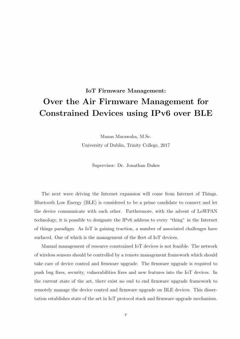
The next wave driving the Internet expansion will come from Internet of Things.
Bluetooth Low Energy (BLE) is considered to be a prime candidate to connect and let
the device communicate with each other. Furthermore, with the advent of LoWPAN
technology, it is possible to designate the IPv6 address to every “thing” in the Internet
of things paradigm. As IoT is gaining traction, a number of associated challenges have
surfaced. One of which is the management of the fleet of IoT devices.
Manual management of resource constrained IoT devices is not feasible. The network
of wireless sensors should be controlled by a remote management framework which should
take care of device control and firmware upgrade. The firmware upgrade is required to
push bug fixes, security, vulnerabilities fixes and new features into the IoT devices. In
the current state of the art, there exist no end to end firmware upgrade framework to
remotely manage the device control and firmware upgrade on BLE devices. This disser-
tation establishes state of the art in IoT protocol stack and firmware upgrade mechanism.
v
Further, we investigate the gaps in current firmware upgrade mechanism and implements
an approach which adheres the specifications of remote management standard (LwM2M)
and uses CoAP block transfer for transporting the firmware image to BLE based IoT
device via IPv6 over BLE channel.
vi

Contents
Acknowledgments iv
Abstract v
List of Tables x
List of Figures xi
Chapter 1 Introduction 1
1.1 Background . . . . . . . . . . . . . . . . . . . . . . . . . . . . . . . . . . . 1
1.2 Motivation . . . . . . . . . . . . . . . . . . . . . . . . . . . . . . . . . . . . 2
1.3 Research Objectives . . . . . . . . . . . . . . . . . . . . . . . . . . . . . . . 4
1.4 Dissertation Structure . . . . . . . . . . . . . . . . . . . . . . . . . . . . . 4
Chapter 2 State of the Art 6
2.1 Introduction . . . . . . . . . . . . . . . . . . . . . . . . . . . . . . . . . . . 6
2.2 Communication Models . . . . . . . . . . . . . . . . . . . . . . . . . . . . . 6
2.3 IoT Communication Stack . . . . . . . . . . . . . . . . . . . . . . . . . . . 10
2.3.1 Data Interchange Formats . . . . . . . . . . . . . . . . . . . . . . . 11
2.3.2 Application Layer . . . . . . . . . . . . . . . . . . . . . . . . . . . . 13
2.3.3 Transport and Communication Layer . . . . . . . . . . . . . . . . . 16
2.3.4 Link Layer . . . . . . . . . . . . . . . . . . . . . . . . . . . . . . . . 19
2.3.5 Device Management . . . . . . . . . . . . . . . . . . . . . . . . . . 24
vii

2.3.6 Security . . . . . . . . . . . . . . . . . . . . . . . . . . . . . . . . . 25
2.4 IPv6 Over BLE . . . . . . . . . . . . . . . . . . . . . . . . . . . . . . . . . 26
2.5 Firmware update for Constrained Devices . . . . . . . . . . . . . . . . . . 28
2.6 A survey on IoT platforms . . . . . . . . . . . . . . . . . . . . . . . . . . . 31
Chapter 3 Design 34
3.1 Requirement . . . . . . . . . . . . . . . . . . . . . . . . . . . . . . . . . . . 34
3.2 System Architecture . . . . . . . . . . . . . . . . . . . . . . . . . . . . . . 35
3.3 OMA Lightweight M2M . . . . . . . . . . . . . . . . . . . . . . . . . . . . 36
3.3.1 LwM2M Firmware Upgrade Mechanism . . . . . . . . . . . . . . . . 38
3.4 Firmware Transfer using CoAP Block Transfer . . . . . . . . . . . . . . . . 40
3.5 Firmware Validation . . . . . . . . . . . . . . . . . . . . . . . . . . . . . . 41
3.6 Flash Operation and Bootloader . . . . . . . . . . . . . . . . . . . . . . . . 42
3.7 High Level Design . . . . . . . . . . . . . . . . . . . . . . . . . . . . . . . . 44
Chapter 4 Prototype Implementation and Evaluation 47
4.1 Introduction . . . . . . . . . . . . . . . . . . . . . . . . . . . . . . . . . . . 47
4.2 Requirement . . . . . . . . . . . . . . . . . . . . . . . . . . . . . . . . . . . 47
4.2.1 Hardware Platform . . . . . . . . . . . . . . . . . . . . . . . . . . . 47
4.2.2 Software Platform . . . . . . . . . . . . . . . . . . . . . . . . . . . . 49
4.3 Software Setup and Configurations . . . . . . . . . . . . . . . . . . . . . . 54
4.4 Software Implementation and Interaction . . . . . . . . . . . . . . . . . . . 58
4.5 Data Structure . . . . . . . . . . . . . . . . . . . . . . . . . . . . . . . . . 66
4.6 Evaluation . . . . . . . . . . . . . . . . . . . . . . . . . . . . . . . . . . . . 67
4.6.1 Firmware Download and Firmware Update . . . . . . . . . . . . . . 67
4.6.2 Firmware download time with different size of RAM buffer . . . . . 68
Chapter 5 Conclusion and Future Work 70
5.1 Introduction . . . . . . . . . . . . . . . . . . . . . . . . . . . . . . . . . . . 70
viii
5.2 Prototype . . . . . . . . . . . . . . . . . . . . . . . . . . . . . . . . . . . . 70
5.3 Contributions . . . . . . . . . . . . . . . . . . . . . . . . . . . . . . . . . . 71
5.4 Challenges . . . . . . . . . . . . . . . . . . . . . . . . . . . . . . . . . . . . 71
5.5 Future Work . . . . . . . . . . . . . . . . . . . . . . . . . . . . . . . . . . . 72
5.5.1 Energy Efficient Updates . . . . . . . . . . . . . . . . . . . . . . . . 72
5.5.2 Firmware Upgrade in a mesh network . . . . . . . . . . . . . . . . . 73
5.5.3 Security implication of firmware upgrade . . . . . . . . . . . . . . . 73
5.5.4 Performance Evaluation . . . . . . . . . . . . . . . . . . . . . . . . 74
5.6 Conclusion . . . . . . . . . . . . . . . . . . . . . . . . . . . . . . . . . . . . 74
Appendix A Abbreviations and Acronyms 75
Appendix B LwM2M Firmware Update Specification 76
Bibliography 79
ix
List of Tables
2.1 A survey of IoT OS . . . . . . . . . . . . . . . . . . . . . . . . . . . . . . . 33
4.1 Data Structures. . . . . . . . . . . . . . . . . . . . . . . . . . . . . . . . . 66
4.2 Results for Experiment #1. . . . . . . . . . . . . . . . . . . . . . . . . . . 69
B.1 Firmware Object Definition [31]. . . . . . . . . . . . . . . . . . . . . . . . . 76
B.3 Firmware Resource Definition [31]. . . . . . . . . . . . . . . . . . . . . . . 78
x
List of Figures
1.1 The Internet of Things Ecosystem. . . . . . . . . . . . . . . . . . . . . . . 2
2.1 Example of device-to-device communication model [5]. . . . . . . . . . . . 7
2.2 Example of device-to-cloud communication model [5]. . . . . . . . . . . . . 8
2.3 Example of device-to-gateway communication model [5]. . . . . . . . . . . 9
2.4 Example of back end data sharing communication model [5]. . . . . . . . . 10
2.5 From web application to IoT node stack. . . . . . . . . . . . . . . . . . . . 11
2.6 CoAP GET request elicits a 200 OK response [11]. . . . . . . . . . . . . . 14
2.7 Web architecture with HTTP and CoAP [11]. . . . . . . . . . . . . . . . . 15
2.8 MQTT Publish/Subscribe Model . . . . . . . . . . . . . . . . . . . . . . . 16
2.9 6LoWPAN Network Architecture 1 . . . . . . . . . . . . . . . . . . . . . . 20
2.10 Bluetooth Low Energy Stack [24] . . . . . . . . . . . . . . . . . . . . . . . 21
2.11 IEEE 802.15.4 Software Stack Architecture . . . . . . . . . . . . . . . . . . 24
2.12 M2M device management framework [30]. . . . . . . . . . . . . . . . . . . 25
2.13 Communication Stack for IPv6 over BLE [24] . . . . . . . . . . . . . . . . 27
2.14 Star Topology of Bluetooth Connected Device [26] . . . . . . . . . . . . . . 28
2.15 Architecture for Autonomous update [34] . . . . . . . . . . . . . . . . . . . 29
3.1 System Architecture . . . . . . . . . . . . . . . . . . . . . . . . . . . . . . 35
3.2 LwM2M Architecture [31] . . . . . . . . . . . . . . . . . . . . . . . . . . . 37
3.3 Firmware Update Mechanism [31]. . . . . . . . . . . . . . . . . . . . . . . . 39
3.4 Example of client fetching firmware image [31]. . . . . . . . . . . . . . . . . 41
xi
3.5 Firmware image with extended header containing. . . . . . . . . . . . . . . 42
3.6 Flash bank with separate partition for new firmware. . . . . . . . . . . . . 43
3.7 High Level Software Design . . . . . . . . . . . . . . . . . . . . . . . . . . 45
3.8 LwM2M Request Format . . . . . . . . . . . . . . . . . . . . . . . . . . . . 46
4.1 nRF52 Soc and CSR Bluetooth V4.0 Dongle. . . . . . . . . . . . . . . . . . 48
4.2 Contiki Network Stack.2 . . . . . . . . . . . . . . . . . . . . . . . . . . . . 50
4.3 BLE enabled IoT Network.3 . . . . . . . . . . . . . . . . . . . . . . . . . . 51
4.4 Protocol stack of Nordic IoT SDK.footnotemark[8] . . . . . . . . . . . . . . 51
4.5 UI of Leshan Server shows interaction with NRF device. . . . . . . . . . . 54
4.6 IPv6 Stateless Auto-Configuration.8 . . . . . . . . . . . . . . . . . . . . . . 57
4.7 Master Sequence Diagram. . . . . . . . . . . . . . . . . . . . . . . . . . . . 59
4.8 System Initialization Flow . . . . . . . . . . . . . . . . . . . . . . . . . . . 60
4.9 Device Registration with Leshan Server. . . . . . . . . . . . . . . . . . . . 61
4.10 Firmware Update UI of Leshan Server . . . . . . . . . . . . . . . . . . . . 62
4.11 CoAP block transfer messages in wireshark . . . . . . . . . . . . . . . . . . 63
4.12 Firmware blocks collection into RAM buffer . . . . . . . . . . . . . . . . . 64
4.13 Flash Memory Layout of a 512kB nrf52 device.8 . . . . . . . . . . . . . . . 65
xii
Chapter 1
Introduction
1.1 Background
The Internet of Things, or IoT, is emerging as the next technology revolution. The term
“Internet of Things” was coined by Kevin Ashton while working with Auto-ID Center at
MIT1. The Internet of Things allows small devices to be sensed or controlled across the
existing internet infrastructure. The network of these connected devices would lead to
the merging of physical and digital worlds, opening up a host of new opportunities and
challenges for consumers, companies, and governments[1]. As estimated by various market
surveys2, billions of everyday devices ranging from wearables to industrial equipment will
be connected in coming years.
A number of significant factors have given the thrust for enabling IoT in real scenar-
ios. These include ubiquitous connectivity, widespread adoption of IP-based networking,
computing economics, miniaturization, advances in data analytics, and the rise of cloud
computing [2]. The applicability of IoT can be broken up into five key verticals of adop-
tion: connected wearable devices, connected cars, connected homes, connected cities, and
the industrial Internet.
In its simplest form, IoT is just about enabling connectivity between “things” or de-
1https://en.wikipedia.org/wiki/Internet of things2http://www.gartner.com/technology/research/internet-of-things/
1
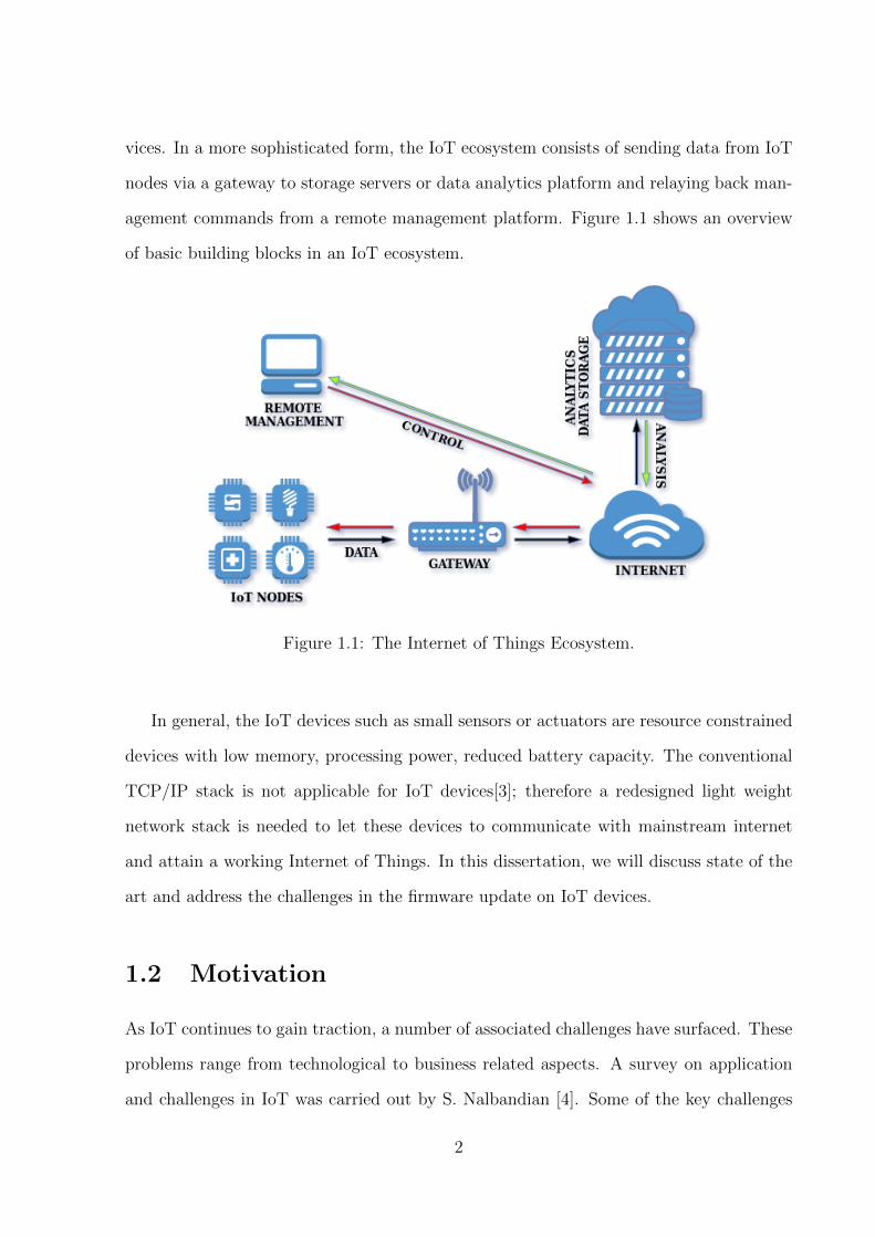
vices. In a more sophisticated form, the IoT ecosystem consists of sending data from IoT
nodes via a gateway to storage servers or data analytics platform and relaying back man-
agement commands from a remote management platform. Figure 1.1 shows an overview
of basic building blocks in an IoT ecosystem.
Figure 1.1: The Internet of Things Ecosystem.
In general, the IoT devices such as small sensors or actuators are resource constrained
devices with low memory, processing power, reduced battery capacity. The conventional
TCP/IP stack is not applicable for IoT devices[3]; therefore a redesigned light weight
network stack is needed to let these devices to communicate with mainstream internet
and attain a working Internet of Things. In this dissertation, we will discuss state of the
art and address the challenges in the firmware update on IoT devices.
1.2 Motivation
As IoT continues to gain traction, a number of associated challenges have surfaced. These
problems range from technological to business related aspects. A survey on application
and challenges in IoT was carried out by S. Nalbandian [4]. Some of the key challenges
2
are summarized below.
• Standards: Lack of standards and documented best practices limits the potential
of IoT. Without standards to guide, manufacturers or developers sometimes design
the products that operate in nonstandard ways which impact the interoperability.
A poorly designed and configured device can have negative consequences for the
networking resources.
• Device Management and Firmware Upgrade: IoT devices are often deployed in a
remote location where the manual administration of these resource constrained de-
vices is not feasible. Upgrading the firmware on these devices is one of the key
challenges in IoT ecosystem. The firmware upgrade is required to push bug fix,
security vulnerabilities fix and new features into the IoT devices. For a seamless in-
tegration of connected devices, a network of wireless sensors should be controlled by
a remote management server which should take care of device control and firmware
upgrade.
• Connectivity: The current connectivity method relies on the centralized, server/-
client paradigm to authenticate, authorize and connect different nodes in a network.
With more and more devices coming into the network it will defy the very structure
of current communication models and the underlying technologies.
• Privacy: More and more data generation from IoT networks creates a unique chal-
lenge to privacy. This is becoming more prevalent in consumer devices, such as
tracking devices for phones and cars as well as smart televisions.
• Security: There are no stringent security standards enforced till now to prevent
attacks in IoT network. With the increase in the number of connected devices
increases the opportunity to exploit security vulnerabilities in the poorly designed
IoT networks.
3

The above-discussed challenges lie in different domains of IoT. In this dissertation,
we primarily focused on identifying and addressing the gaps realted to device man-
agement and firmware upgrade in IoT devices.
1.3 Research Objectives
On the commercial basis, there is a need of automating the firmware upgrade on sensor
networks to reduce manual interventions. In the current state of the art, there is no end
to end standardized approach for remotely managing the firmware on IoT devices and
pushing new firmware when required. With the availability of energy efficient LoWPAN
technology and broad adoption of BLE, this dissertation aims to investigate and imple-
ment a standard complaint end to end firmware management system for BLE based IoT
devices using IPv6 over BLE compliant communication stack.
The research objective can be further divided into sub-objectives as listed below:
1. Establish state of the art for the IoT protocol stack.
2. Establish state of the art for firmware management of resource constrained devices.
3. Identify the gaps in the current state of the art for firmware management of resource
constrained devices.
4. Design a standard compliant end to end firmware management architecture and for
BLE based IoT devices using IPv6 over BLE compliant communication stack to
address the gaps in the current state of the art.
1.4 Dissertation Structure
This section provides an outline of the structure of the thesis document.
• The current chapter provides a brief overview of the areas of research; motivation,
research objectives and goals of this dissertation.
4
• Chapter 2 divides the objective into specific areas of research. The state-of-the-art,
background and related work for each of these areas are discussed in corresponding
sections.
• Chapter 3 specifies the design aspects of the proposed system. The requirements
of the system, the system architecture, and high-level design are discussed in this
chapter.
• Chapter 4 discusses the methods, technologies, and platform used to implement
the proof of concept of a firmware management system. The specific libraries,
programming tools, languages, and software setup used are specified in the chapter.
A discussion on system evaluation is also presented in this chapter.
• Chapter 5 summarizes the contributions made by this research, lists future work
and concludes with final remarks on the dissertation.
5
Chapter 2
State of the Art
2.1 Introduction
In this chapter, we will look into the communication models being followed in IoT network
deployment and proposed lightweight stack for IoT devices. In the recent years, there is a
lot of work done in standardizing protocols to make IoT solution inter operable. We will
discuss different protocols and standards applicable in IoT stack. Finally, we will discuss
the principles, challenges and acknowledge the work done by the researcher community
in the field of firmware updates on resource constrained IoT devices.
2.2 Communication Models
Regarding operations, it is necessary to define how IoT devices should connect and com-
municate. The Internet Architecture Board (IAB)1 released the guiding specification
RFC-7452 [5] to design Internet connected smart objects, which defines a number of
communication patterns utilized in the smart object environment. The discussion below
presents the defined pattern with the key characteristics of each model.
1https://www.iab.org/
6
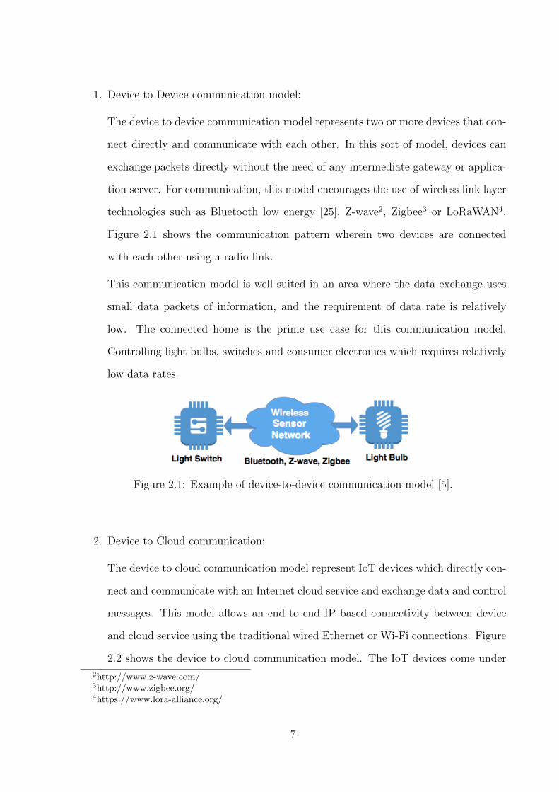
1. Device to Device communication model:
The device to device communication model represents two or more devices that con-
nect directly and communicate with each other. In this sort of model, devices can
exchange packets directly without the need of any intermediate gateway or applica-
tion server. For communication, this model encourages the use of wireless link layer
technologies such as Bluetooth low energy [25], Z-wave2, Zigbee3 or LoRaWAN4.
Figure 2.1 shows the communication pattern wherein two devices are connected
with each other using a radio link.
This communication model is well suited in an area where the data exchange uses
small data packets of information, and the requirement of data rate is relatively
low. The connected home is the prime use case for this communication model.
Controlling light bulbs, switches and consumer electronics which requires relatively
low data rates.
Figure 2.1: Example of device-to-device communication model [5].
2. Device to Cloud communication:
The device to cloud communication model represent IoT devices which directly con-
nect and communicate with an Internet cloud service and exchange data and control
messages. This model allows an end to end IP based connectivity between device
and cloud service using the traditional wired Ethernet or Wi-Fi connections. Figure
2.2 shows the device to cloud communication model. The IoT devices come under
2http://www.z-wave.com/3http://www.zigbee.org/4https://www.lora-alliance.org/
7
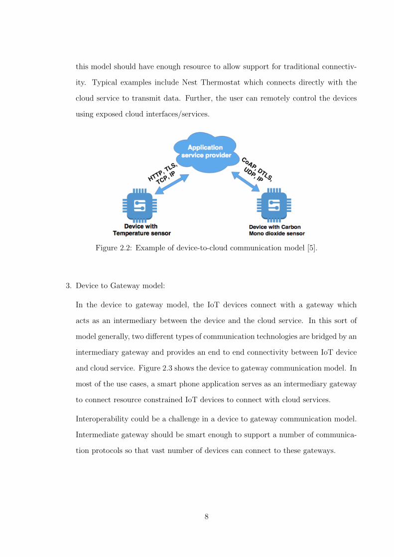
this model should have enough resource to allow support for traditional connectiv-
ity. Typical examples include Nest Thermostat which connects directly with the
cloud service to transmit data. Further, the user can remotely control the devices
using exposed cloud interfaces/services.
Figure 2.2: Example of device-to-cloud communication model [5].
3. Device to Gateway model:
In the device to gateway model, the IoT devices connect with a gateway which
acts as an intermediary between the device and the cloud service. In this sort of
model generally, two different types of communication technologies are bridged by an
intermediary gateway and provides an end to end connectivity between IoT device
and cloud service. Figure 2.3 shows the device to gateway communication model. In
most of the use cases, a smart phone application serves as an intermediary gateway
to connect resource constrained IoT devices to connect with cloud services.
Interoperability could be a challenge in a device to gateway communication model.
Intermediate gateway should be smart enough to support a number of communica-
tion protocols so that vast number of devices can connect to these gateways.
8
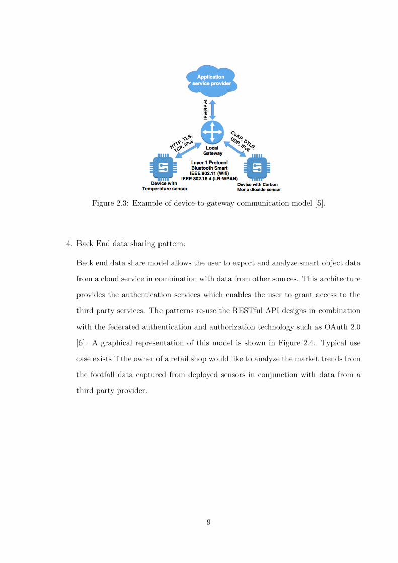
Figure 2.3: Example of device-to-gateway communication model [5].
4. Back End data sharing pattern:
Back end data share model allows the user to export and analyze smart object data
from a cloud service in combination with data from other sources. This architecture
provides the authentication services which enables the user to grant access to the
third party services. The patterns re-use the RESTful API designs in combination
with the federated authentication and authorization technology such as OAuth 2.0
[6]. A graphical representation of this model is shown in Figure 2.4. Typical use
case exists if the owner of a retail shop would like to analyze the market trends from
the footfall data captured from deployed sensors in conjunction with data from a
third party provider.
9
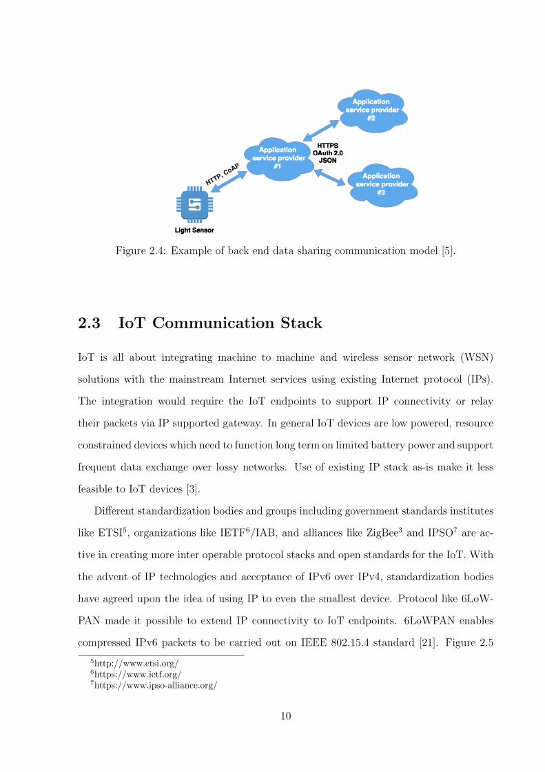
Figure 2.4: Example of back end data sharing communication model [5].
2.3 IoT Communication Stack
IoT is all about integrating machine to machine and wireless sensor network (WSN)
solutions with the mainstream Internet services using existing Internet protocol (IPs).
The integration would require the IoT endpoints to support IP connectivity or relay
their packets via IP supported gateway. In general IoT devices are low powered, resource
constrained devices which need to function long term on limited battery power and support
frequent data exchange over lossy networks. Use of existing IP stack as-is make it less
feasible to IoT devices [3].
Different standardization bodies and groups including government standards institutes
like ETSI5, organizations like IETF6/IAB, and alliances like ZigBee3 and IPSO7 are ac-
tive in creating more inter operable protocol stacks and open standards for the IoT. With
the advent of IP technologies and acceptance of IPv6 over IPv4, standardization bodies
have agreed upon the idea of using IP to even the smallest device. Protocol like 6LoW-
PAN made it possible to extend IP connectivity to IoT endpoints. 6LoWPAN enables
compressed IPv6 packets to be carried out on IEEE 802.15.4 standard [21]. Figure 2.5
5http://www.etsi.org/6https://www.ietf.org/7https://www.ipso-alliance.org/
10

below shows the typical web application stack and redesigned IoT network stack suitable
to provide IP connectivity in low powered, resource constraint IoT nodes. This section
further discusses each layer of IoT protocol stack in more detail.
Figure 2.5: From web application to IoT node stack.
2.3.1 Data Interchange Formats
Data interchange formats are required to let the applications speak to each other in a
standard format. These formats are responsible for representation of structured data.
This section further discusses the formats suitable for IoT stack.
1. JAVA SCRIPT OBJECT NOTATION (JSON)
RFC-7159 [7] defines the specification of JSON data interchange format. JSON is a
lightweight text format which allows structured data interchange. It is completely
language independent but uses conventions associated with conventional program-
ming languages such as C, C++, C#, Java, JavaScript, Perl, Python, etc. It was
11
first introduced to the world at json.org website8. The syntax of JSON is a collection
of braces, brackets, colons, and commas that are used to define structured data. On
principle, JSON is built on two universal data structure.
(a) Collection of name value pair: Implemented as hash tables, associative arrays,
or dictionary
(b) An ordered list of values: Implemented as an array, vector, or list.
These universal data structures are supported by virtually all the programming lan-
guages which make it suitable for programming languages to have a data interchange
format based on standard data structures.
2. Concise Binary Object Representation (CBOR)
RFC-7049 [8] defines the specification of CBOR data exchange format. CBOR
is a binary data serialization format which is based on JSON data interchange
format. The design goals of CBOR includes the possibility of minimal code size,
fairly small message size, and extensibility without the need for version negotiation
[8]. CBOR is a recommended data serialization layer for the CoAP IoT protocol
suite9. Implementation of CBOR is simple and provided in various languages10.
Internet of Things is a major factor in the development of CBOR. Binary encoding
in CBOR allows faster processing.
3. IPSO Alliance
The potential of the Internet of things can be best exploited with IP as a connec-
tivity medium. The IPSO alliance7 is an organization which promotes the Internet
protocol (IP) for IoT device communication. With rapid integration of small de-
vices, IETF has provided a specification for IP-enabled IoT devices to work in a web
like fashion. There is a need to structured data model on top of application layer
8http://www.json.org/9http://coap.technology/
10http://cbor.io/impls.html
12
protocol to allow seamless communication with these small devices. IPSO provides a
common design pattern, an object model to provide interoperability between smart
object device and connected software application on devices and services [9]. IPSO
defined object model is based on Open Mobile Alliance Lightweight Specification
(OMA LwM2M) [31].
The data model followed by IPSO is in the form of CoAP URI /Object/Instance/Re-
source and identical to one which is followed by LwM2M. Section 3.7 provide details
about the Data models and object representation.
2.3.2 Application Layer
IoT is about interactions between multiple devices, things, and objects. Interaction of
devices and services will exploit the actual potential of IoT. The application layer is re-
sponsible for providing services and determines a set of protocols for message passing at
the application level. M. B. Yassein et al., [10] provides a survey and comparison of differ-
ent application protocols based on transport layer used, architecture and communication
model. This section further discusses the application layer protocol suitable for IoT.
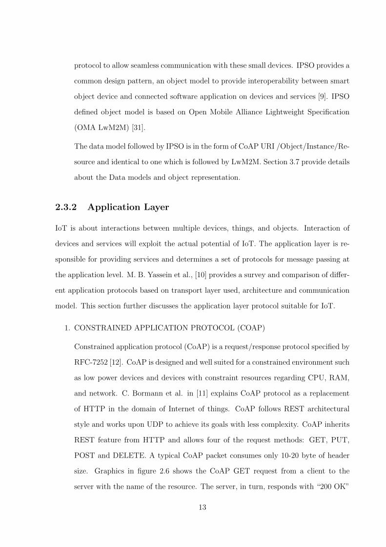
1. CONSTRAINED APPLICATION PROTOCOL (COAP)
Constrained application protocol (CoAP) is a request/response protocol specified by
RFC-7252 [12]. CoAP is designed and well suited for a constrained environment such
as low power devices and devices with constraint resources regarding CPU, RAM,
and network. C. Bormann et al. in [11] explains CoAP protocol as a replacement
of HTTP in the domain of Internet of things. CoAP follows REST architectural
style and works upon UDP to achieve its goals with less complexity. CoAP inherits
REST feature from HTTP and allows four of the request methods: GET, PUT,
POST and DELETE. A typical CoAP packet consumes only 10-20 byte of header
size. Graphics in figure 2.6 shows the CoAP GET request from a client to the
server with the name of the resource. The server, in turn, responds with “200 OK”
13

response code, data format and requested data[11].
Figure 2.6: CoAP GET request elicits a 200 OK response [11].
CoAP provides three main features: Block transfer, Observe and Discover.
(a) Block Transfer: Block transfer will overcome the situation of fragments where
large data needs to be transferred such as firmware update. CoAP transfers
multiple blocks of information for a resource representation by simply adding
a pair of “Block options.”
(b) Observe: Using observe, the client will subscribe to a resource in server and
server will send out a notification in case of any change in the resource.
(c) Discover: Discover will expose a “well-known” resource using which devices
will be able to discover each other and their resources.
Figure 2.7 shows the inter working of CoAP with HTTP. The proxies in between can
behave like intermediately which can speak both CoAP and HTTP this providing
the interoperability between CoAP based network and traditional HTTP based
Internet.
14
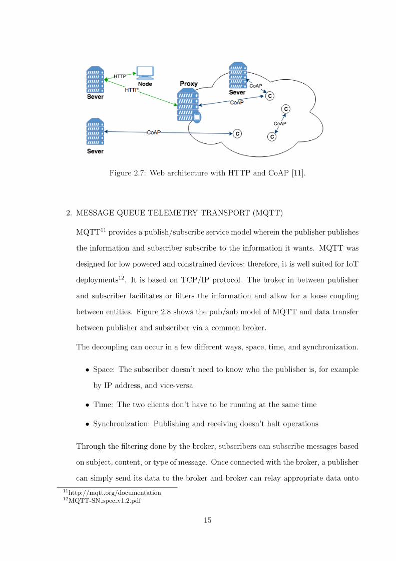
Figure 2.7: Web architecture with HTTP and CoAP [11].
2. MESSAGE QUEUE TELEMETRY TRANSPORT (MQTT)
MQTT11 provides a publish/subscribe service model wherein the publisher publishes
the information and subscriber subscribe to the information it wants. MQTT was
designed for low powered and constrained devices; therefore, it is well suited for IoT
deployments12. It is based on TCP/IP protocol. The broker in between publisher
and subscriber facilitates or filters the information and allow for a loose coupling
between entities. Figure 2.8 shows the pub/sub model of MQTT and data transfer
between publisher and subscriber via a common broker.
The decoupling can occur in a few different ways, space, time, and synchronization.
• Space: The subscriber doesn’t need to know who the publisher is, for example
by IP address, and vice-versa
• Time: The two clients don’t have to be running at the same time
• Synchronization: Publishing and receiving doesn’t halt operations
Through the filtering done by the broker, subscribers can subscribe messages based
on subject, content, or type of message. Once connected with the broker, a publisher
can simply send its data to the broker and broker can relay appropriate data onto
11http://mqtt.org/documentation12MQTT-SN spec v1.2.pdf
15
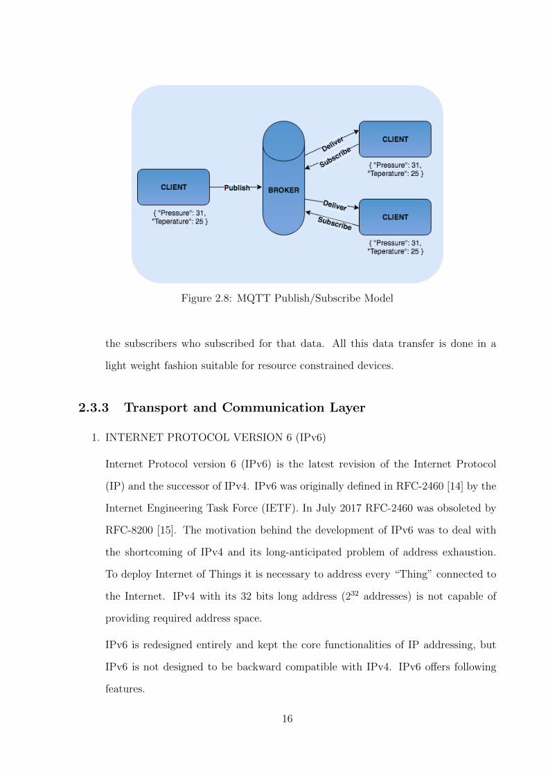
Figure 2.8: MQTT Publish/Subscribe Model
the subscribers who subscribed for that data. All this data transfer is done in a
light weight fashion suitable for resource constrained devices.
2.3.3 Transport and Communication Layer
1. INTERNET PROTOCOL VERSION 6 (IPv6)
Internet Protocol version 6 (IPv6) is the latest revision of the Internet Protocol
(IP) and the successor of IPv4. IPv6 was originally defined in RFC-2460 [14] by the
Internet Engineering Task Force (IETF). In July 2017 RFC-2460 was obsoleted by
RFC-8200 [15]. The motivation behind the development of IPv6 was to deal with
the shortcoming of IPv4 and its long-anticipated problem of address exhaustion.
To deploy Internet of Things it is necessary to address every “Thing” connected to
the Internet. IPv4 with its 32 bits long address (232 addresses) is not capable of
providing required address space.
IPv6 is redesigned entirely and kept the core functionalities of IP addressing, but
IPv6 is not designed to be backward compatible with IPv4. IPv6 offers following
features.
16
• Larger Address Space [15]: The full version of IPv6 address is as long as 128
bits which is in contrast to IPv4, four times more bits to address a device on
the Internet. The full address range of IPv6 can provide approximately 2128
different combinations of addresses. This address can accumulate the aggressive
requirement of address allotment for almost everything in this world.
• Simplified Header [15]: In IPv6’s header all the unnecessary information is
moved to end of the header and used as an option. Wherein in case of IPv4
header the information is tied to the header. In this way, IPv6 header is more
simplified and can be compressible.
• End-to-end Connectivity: Every system now has a unique IP address and can
traverse through the Internet without using NAT or other translating com-
ponents. After IPv6 is fully implemented, every host can directly reach other
hosts on the Internet, with some limitations involved like Firewall, organization
policies, etc.
• Auto-configuration [17]: IPv6 supports both stateful and stateless auto con-
figuration mode of its host devices. This way, the absence of a DHCP server
does not put a halt on inter segment communication.
• IPSec [18]: An optional feature of providing IPsec security is included in IPv6
which makes it more secure than IPv4.
• Anycast Support: In this mode, multiple interfaces over the Internet are as-
signed same Anycast IP address. Routers, while routing, send the packet to
the nearest destination.
• Mobility [19]: IPv6 was designed keeping mobility in mind. This feature en-
ables hosts (such as mobile phone) to roam around in a different geographical
area and remain connected with the same IP address. The mobility feature of
IPv6 takes advantage of auto IP configuration and Extension headers.
Z. Jun et al., [20] explained how IPv6 is could be a key enabling factor in IoT and
17
suitable for wireless sensor networks.
(a) Enormous address space of IPv6 can cater every device.
(b) Mobile IPv6 avoids triangulation and can be as efficient as normal IPv6.
(c) Internet protocol security (IPsec) is mandatory in IPv6 which can satisfy se-
curity requirement.
(d) Neighbor discovery meets the need of WSNs such as router discovery, parameter
discovery, and address auto configuration.
Z. Jun et al., [20] also proposes an improved, simplified IPv6 addressing scheme for
addressing formats in intra-WSN communication. The full version of IPv6 address
is as long as 128 bits, and the data payload in WSNs is quite small. Processing an
address with full IPv6 addressing would be a big hit in the performance of WSNs
thus compressing the control section is of great importance for energy. The author
explained the use of IPv6 prefixes in a sensor node. Often WSNs adopts prefix
001(2000::/3) which is not suitable for WSNs as computer networks often utilize
it. Author proposed prefix 0100::/8 as a new address section of WSNs. There are
techniques available which compress the IPv6 address inside a WSNs networks and
added to data packets when packets are directed to an external IPv6 network. One
such technique is 6LoWPAN which provides IPv6 networking over IEEE 802.15.4.
2. IPv6 over Low-Power Wireless Personal Area Network (6LoWPAN)
6LoWPAN is an open standard defined in RFC-6282[21] by the Internet Engineering
Task Force (IETF). It introduces an adaption layer between network and link layer
and enables the efficient transfer of IPv6 data packets by reducing the IP overheads.
6LoWPAN works on the principle of stateless compression to elide adaptation net-
work, and transport-layer header fields, compressing all three layers down to a few
bytes. The adaptation layer has three primary elements mentioned below.
(a) Header compression
18
(b) Fragmentation
(c) Layer two forwarding
W. hui et al.[22] describes the 6LoWPAN header arrangements; it uses header stack-
ing to keep orthogonal concepts separate and enforce a clear method for expressing
its capabilities. 6LoWPAN also provides support for Mesh under and Route over
routing. In the former routing method network stack has no role in routing instead,
the adaptation layer masks the lack of a full broadcast at the physical level by trans-
parently routing and forwarding packets within the LoWPAN. In route over routing
is done at the IP layer, with each node serving as an IP router.
Figure 2.9 shows the network architecture of 6LoWPAN including IPv6 network.
The 6LoWPAN network is connected to the IPv6 network using an edge router and
typically operate on the edge, acting as stub networks. The edge router handles
three actions:
(a) The data exchange between 6LoWPAN devices and the Internet (or other IPv6
network).
(b) Local data exchange between devices inside the 6LoWPAN.
(c) The generation and maintenance of the radio subnet (the 6LoWPAN network).
Two other device types are included in a typical 6LoWPAN network: routers and
hosts. Router do the work of routing data between the nodes in the 6LoWPAN
network and hosts are the end devices and are not capable of routing data in the
network. A host could be low powered devices which wake up periodically to check
its parent for data.
2.3.4 Link Layer
1. Bluetooth Low Energy (BLE)
13http://www.ti.com/lit/wp/swry013/swry013.pdf
19

Figure 2.9: 6LoWPAN Network Architecture 13
Bluetooth Low Energy (BLE), also referred to a Bluetooth Smart is the Bluetooth
4.0 core specification. The widespread use of BLE makes it a perfect choice to enable
networking solution on Internet of thing devices. BLE is particularly designed for
short range communication and monitoring applications that are expected to be
incorporated into billions of devices in the next few years [24]. Bluetooth low energy
is not backward compatible to the classic Bluetooth as it was designed to provide
low cost, low bandwidth, low power and less complex radio standard. Since BLE is
rapidly adopted in the smartphone, this gives an opportunity for a number of BLE
based use cases in areas such as healthcare, consumer electronics, smart energy, and
security. Furthermore, the power efficiency of BLE is considered to be a key factor
which makes the BLE to be preferred choice compared to its competitors like Wi-Fi,
Zigbee3, etc.
Bluetooth protocol stack consists of two main components: The Controller and
20
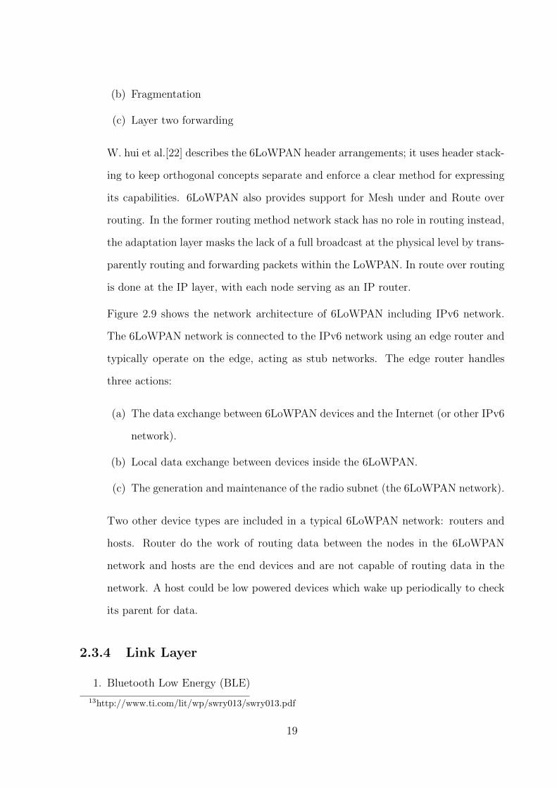
the Host [25]. The controller takes care of physical layer and link layer of BLE
stack and is typically implemented in the form of System-on-a-Chip (SoC) with an
integrated radio. The host runs on application processor and includes application-
level functionality. Graphics in figure 2.10 shows the BLE protocol stack and a short
description of all the layers is mentioned below:
Figure 2.10: Bluetooth Low Energy Stack [24]
(a) Attribute Protocol (ATT): The ATT defines the communication between two
devices playing server and client role. The server maintains a set of attributes
which stores the information managed by GATT protocol. The client and
server role is defined by GATT and does not relate to the role of central and
peripheral. The client sends out the request to access the attribute on the
server. The server responds back to the client. in terms of notification and
indication messages.
(b) Generic ATT (GATT): The GATT defines the framework that uses the ATT for
discovery services and exchange of characteristic from one device to another. A
characteristic is defined as a set of data which includes a value and properties.
The data related to services and characteristics are stored in attributes
21
(c) Generic Access Profile (GAP): Defines the device role, modes, and procedure
for device discovery and services.
(d) Logical Link Control and Adaptation Layer Protocol (L2CAP): the primary
function of L2CAP is to multiplex the data of three higher layer protocol, ATT,
SMP and Link layer control signaling.
Communication between host and controller takes place using a host controller in-
terface (HCI). BLE defines four roles in its topology which are broadcaster, observer,
peripheral and central.
(a) Broadcaster: transmits data known as advertising packets. Devices like bea-
cons and sensors cannot connect to the broadcaster during the advertisement.
The purpose is to let other devices know of its presence.
(b) Observers: These are receivers which can receive advertising packets from
broadcasters and peripheral devices.
(c) Peripherals: These are devices that connect in a slave role. The broadcaster will
first broadcast their presence so that the central device knows of its existence
and then chose to connect with the device.
(d) Central: These are sophisticated devices and support multiple connections. It
initiates connections to peripherals. This device can be central and peripherals
at the same time.
2. IEEE 802.15.4
IEEE 802.15.4 is a standard defined and maintained by IEEE 802.15 working group14.
IEEE 802.15.4 specifies the operation of low-rate wireless personal area network.
The standard was initially specified in 2003 but superseded by the publication of
IEEE 802.15.4-2006 standard15. The standards specify the physical layer and mac
14http://www.ieee802.org/15/15http://www.ieee802.org/15/pub/TG4.html
22
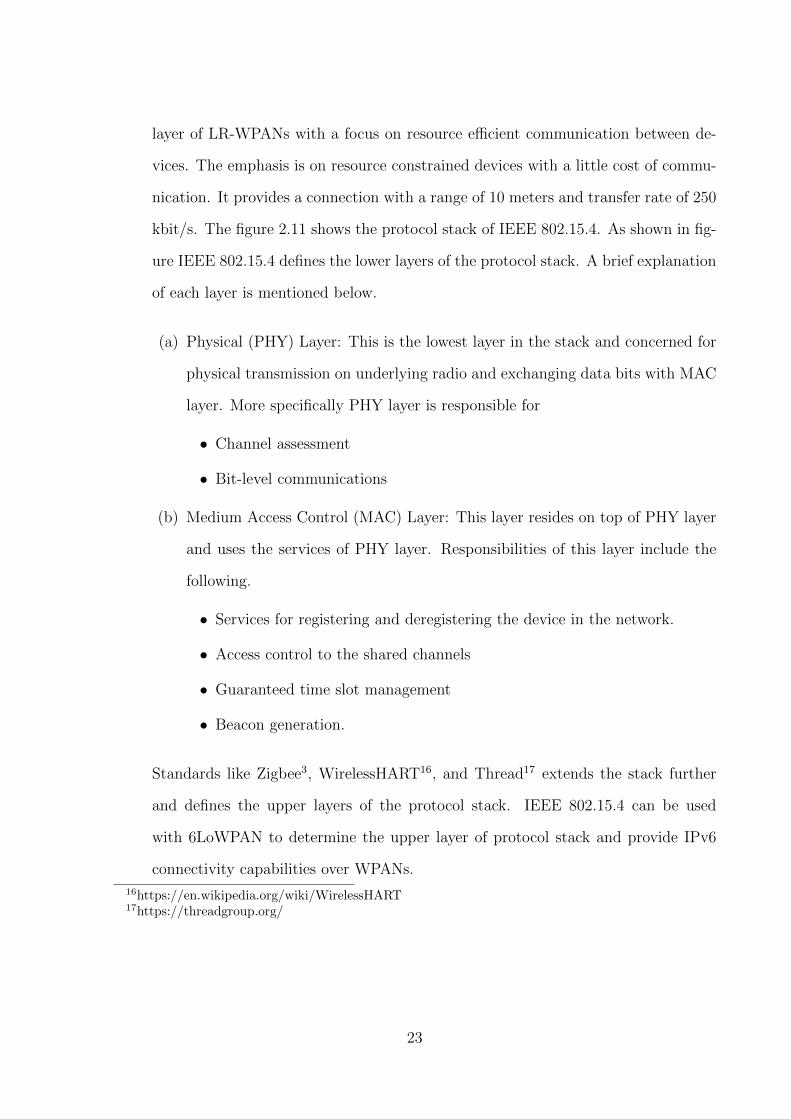
layer of LR-WPANs with a focus on resource efficient communication between de-
vices. The emphasis is on resource constrained devices with a little cost of commu-
nication. It provides a connection with a range of 10 meters and transfer rate of 250
kbit/s. The figure 2.11 shows the protocol stack of IEEE 802.15.4. As shown in fig-
ure IEEE 802.15.4 defines the lower layers of the protocol stack. A brief explanation
of each layer is mentioned below.
(a) Physical (PHY) Layer: This is the lowest layer in the stack and concerned for
physical transmission on underlying radio and exchanging data bits with MAC
layer. More specifically PHY layer is responsible for
• Channel assessment
• Bit-level communications
(b) Medium Access Control (MAC) Layer: This layer resides on top of PHY layer
and uses the services of PHY layer. Responsibilities of this layer include the
following.
• Services for registering and deregistering the device in the network.
• Access control to the shared channels
• Guaranteed time slot management
• Beacon generation.
Standards like Zigbee3, WirelessHART16, and Thread17 extends the stack further
and defines the upper layers of the protocol stack. IEEE 802.15.4 can be used
with 6LoWPAN to determine the upper layer of protocol stack and provide IPv6
connectivity capabilities over WPANs.
16https://en.wikipedia.org/wiki/WirelessHART17https://threadgroup.org/
23

Figure 2.11: IEEE 802.15.4 Software Stack Architecture
2.3.5 Device Management
In a majority of scenarios, remote deployment model is preferred in IoT. Operators can’t
expect the end users to perform any troubleshoot or management operation (such as
firmware updates) on remotely deployed IoT devices. For a seamless integration of con-
nected devices, the network of wireless sensors should be controlled by a remote manage-
ment server which should take care of device control and firmware updates.
S. K. Datta et al., [30] proposes an M2M device management framework that can
address the challenge of managing the fleet of connected M2M devices. The architecture
proposed by the authors follows the specification of open mobile alliance lightweight ma-
chine to machine (OMA LwM2M). It also adheres the CoRE link format [32] to represent
the M2M device and their endpoints using resource types and attributes. The framework
follows a lightweight description of M2M devices which is the key to implement an efficient
and scalable design.
The framework is divided into four layers namely: Perception layer, Proxy layer, Con-
figuration Storage layer and Service Enablement layer. Each layer performs a dedicated
set of functionality to bootstrap and manage the smart and legacy device. In the initializa-
tion phase devices are registered with configuration storage database using configuration
24
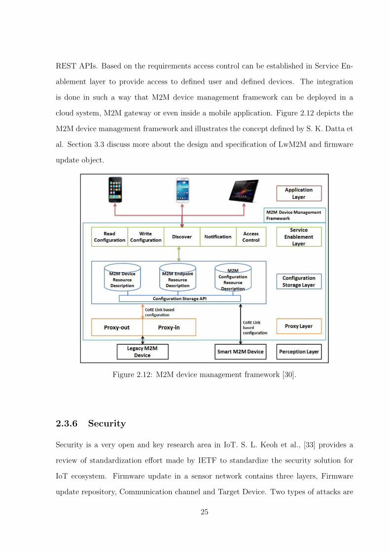
REST APIs. Based on the requirements access control can be established in Service En-
ablement layer to provide access to defined user and defined devices. The integration
is done in such a way that M2M device management framework can be deployed in a
cloud system, M2M gateway or even inside a mobile application. Figure 2.12 depicts the
M2M device management framework and illustrates the concept defined by S. K. Datta et
al. Section 3.3 discuss more about the design and specification of LwM2M and firmware
update object.
Figure 2.12: M2M device management framework [30].
2.3.6 Security
Security is a very open and key research area in IoT. S. L. Keoh et al., [33] provides a
review of standardization effort made by IETF to standardize the security solution for
IoT ecosystem. Firmware update in a sensor network contains three layers, Firmware
update repository, Communication channel and Target Device. Two types of attacks are
25
considered in remote firmware updates (i) Attack on the untrusted communication chan-
nel to access the firmware image while data transport phase (ii) Attack on target device
during firmware loading phase. Both attacks have similar capabilities to perform either
passive (eavesdropping) or active (man-in-the-middle) attacks during firmware transport
and loading phase. Remote management of sensor nodes would require communication
with each node in the sensor network. CoAP which runs on UDP is a preferred choice
concerning communication medium. DTLS is a prime consideration to secure the commu-
nication channel. DTLS is considered to be a complete security protocol which provides
authentication, key exchange, and protection of application data. DTLS provides end to
end secure session between two communicating devices in our case one inside the sensor
network, and other is remote management server [33].
BLE devices are low powered and designed to run several years on a single coin cell
battery. The area of the firmware update is open for vulnerabilities and attack. For a
secure firmware update, it is needed to establish the authenticity of data originated from
the firmware build server. The conventional way of encrypting the data with asymmetric
key cryptography (Digital Signature) would not be suitable for the type of devices in
consideration due to its low computational resource. Use of symmetric key cryptography
would be more appropriate for such devices. A hash function with the combination of
Message authentication code (MAC) could be used to establish the data integrity and
authenticity of firmware update. Working with symmetric key cryptography, there is a
need to ensure the safety of secure MAC key.
2.4 IPv6 Over BLE
Seeing, the widespread usage of BLE and projection of a billion BLE based device in
near future, IETF 6LoWPAN WG standardized RFC-7668 [26] to provide end to end IP
connectivity over BLE. RFC-7668 allows the transportation of IPv6 packets over Blue-
tooth low energy. Work done by J. Nieminen et al. [24] focuses on the enablement of
26

Bluetooth low energy in low powered sensor nodes and connecting these small devices
with the Internet. Figure 2.13 shows the IPv6 over BLE stack proposed by RFC-7668
and implemented by J. Nieminen et al.
Figure 2.13: Communication Stack for IPv6 over BLE [24]
Authors presented the practical implementation of RFC-7668 (When this paper was
written, RFC-7668 was in draft phase) and evaluation of its implementation. IPv6 is not
directly supported over BLE, in this implementation author modifies the already imple-
mented 6LoWPAN adaptation layer to work with BLE. Natively 6LoWPAN is designed
to work with IEEE 802.15.4 standard [21], additional work done by the authors allowed
the modification of 6LoWPAN stack and made it compatible with BLE layer. The author
described various feature (fragmentation, header compression, and neighbor discovery)
provided by 6LoWPAN in context of IEEE 802.15.4 and also talked about enabling these
features in the context of BLE. As shown in figure 2.14, RFC-7668 advocates a star based
topology to connect multiple BLE peripherals with a central BLE device. The central
device will act as 6LBR (Border router/Gateway) as the specified topology is start based,
so there is no scope is 6LR routers as in 6LoWPAN implementation in the context of IEEE
802.15.4. Further work has been identified as an action item to support mesh network-
ing in IPv6 over BLE implementation. At present [27] provides the draft version of the
27
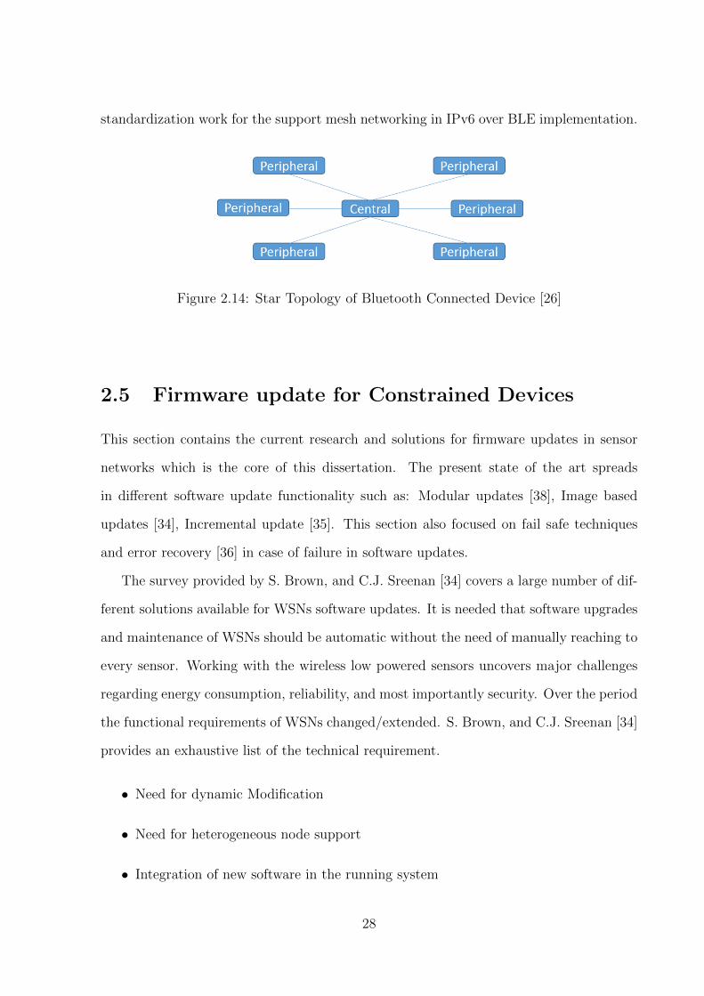
standardization work for the support mesh networking in IPv6 over BLE implementation.
Figure 2.14: Star Topology of Bluetooth Connected Device [26]
2.5 Firmware update for Constrained Devices
This section contains the current research and solutions for firmware updates in sensor
networks which is the core of this dissertation. The present state of the art spreads
in different software update functionality such as: Modular updates [38], Image based
updates [34], Incremental update [35]. This section also focused on fail safe techniques
and error recovery [36] in case of failure in software updates.
The survey provided by S. Brown, and C.J. Sreenan [34] covers a large number of dif-
ferent solutions available for WSNs software updates. It is needed that software upgrades
and maintenance of WSNs should be automatic without the need of manually reaching to
every sensor. Working with the wireless low powered sensors uncovers major challenges
regarding energy consumption, reliability, and most importantly security. Over the period
the functional requirements of WSNs changed/extended. S. Brown, and C.J. Sreenan [34]
provides an exhaustive list of the technical requirement.
• Need for dynamic Modification
• Need for heterogeneous node support
• Integration of new software in the running system
28

• Update should be reliable and reach all nodes
• Handling packet loss in context of software data dissemination in WSNs
• Special boot loader to provide support for fall back.
• Control mechanism for overall management of WSNs
The author also presented functional requirement from energy efficiency point of view.
In energy reduction context techniques such as differential, modular updates are focused
which ultimately reduce the traffic load. As a result, less energy consumption. Figure
2.15 shows the architecture and components of an autonomous firmware update system.
Figure 2.15: Architecture for Autonomous update [34]
M. Stolikj et al., [35] presented his work for efficient reprogramming of wireless sensor
networks using the data compression techniques and incremental updates. Author ex-
ploited the fact that energy used by the processor is significantly less than wireless radio.
The author emphasizes on applying data compression method to a software update in
combination with any incremental update algorithm. These two approaches, could lead
29
to a significant reduction in energy consumption and resource usage. The author analyzed
various other solution such as Contiki, Mate, OSAS, and Zephyr. Out of all only Zephyr
works on principles of incremental updates and all other works on modular and Virtual
machines methodology respectively.
B. Porter et al., [38] proposed a modular upgrade approach and presented Lorien which
is a type-safe modular OS. Lorien is written in a minimal component oriented extension
of C programming language and provides strongly modeled components for strong typing
of software components. Explicit use of constructors and destructors make the dynamic
component instantiation. The overall software configurations (list of modules) are repre-
sented as a collection of pre-component-instance configuration fragments that are held in
a system manifest in program memory.
S. Unterschtz et al., [36] addresses the problem of error-prone software updates which
can disable the update functionality on a sensor node. For a fail safe software updated
author divided firmware deployment process into four sections.
1. Firmware Separation
• Splitting the firmware image into segments and packets and transferring over
the allowed limit of low powered devices such as 100 bytes for IEEE 802.15.4.
• Maintaining a bit vector to store the status of segments and needed retrans-
missions.
2. Dissemination
• A central server will control the dissemination process and based on require-
ment central server will contact selected nodes only instead of flooding the
whole network.
3. Forward Error Correction
• Getting acknowledgment of each received packet will flood the network. To
30

avoid this reed solom coding is used in which for each M packets, extra k
redundant packets.
4. Boot loader and error recovery
• Author emphasizes on the necessity of watch dog timer and locking the boot
loader so that it cant be modified through software updates. Boot loader should
be carefully tested at the time of deployment
We reviewed state of the art for the firmware update in IoT devices. Present work
is related to energy efficient techniques and error detection mechanisms. At the best of
our knowledge, there is no implementation exist which provide an end to end firmware
management system for IoT devices.
2.6 A survey on IoT platforms
Traditional operating system (Windows/Unix) and RTOS does not match with the re-
quirement of small scale IoT device. An operating system for IoT should support the
protocol stack defined in section 2.3. In recent years numerous open source and propri-
etary IoT operating has been rolled out. Work done by O. Hahm, et al. [28] and P. Gaur,
et al. [29] provides a discussion on the required features for an IoT OS and a survey
of current IoT operating system. Ideally, an IoT operating system should comprise of
following feature to support small IoT devices [28].
1. Architecture
2. Programming Model
3. Scheduling
4. Small Memory Footprint
5. Support for Heterogeneous Hardware
31

6. Network Connectivity
7. Energy Efficiency
8. Real-Time Capabilities
9. Security
Table 2.1 provides a survey of IoT operating system in terms features mentioned above.
The survey is partially based on the work done by O. Hahm, et al. [28] and extended
further in terms of features and updated with the current development of compared IoT
operating system.
In this survey, we have analyzed various OSs targeted for resource constrained IoT
device. These devices are not capable to run traditional OS such as Linux. Generally,
all the OSs targeted for IoT devices have supported the minimal IoT stack and protocols
defined in section 2.3. We would also like to mention that in some cases the function-
ality presented by maintainers of a particular OS doesnt go well with the specification.
Practically, while working with some of the OSs defined in the survey, we found broken
support in terms of platform or feature support. It is understandable that these OSes are
developing under open source contribution and project in OSS could take time to mature
in terms of both features and documentation.
32

Nam
eL
icense
Arc
hit
ectu
reP
rogra
mm
ing
Model
Schedule
rP
roto
col
Pla
tform
Language
Mem
ory
Conti
kia
BSD
Monolith
icP
roto
thre
ads
and
events
Coop
era
tive
Lw
M2M
,M
QT
T,
6lo
wpan,
RP
L,
CoA
P,
TL
S,
DT
LS,
Blu
eto
oth
,B
lueto
oth
Low
Energ
y
TI
CC
2538,
nR
F52832,
TI
MSP
430x,
Atm
el
AV
R,
Fre
esc
ale
MC
1322x
C10k
RA
Mand
30k
RO
M
Zephyr
bA
pache
2.0
Monolith
icM
ult
iT
hre
adin
gC
oop
era
tive
and
Pre
em
pti
ve
Lw
M2M
,C
oA
P,
HT
TP
,M
QT
T,
Blu
eto
oth
,B
lueto
oth
Low
Energ
y,
IEE
E802.1
5.4
,6L
oW
PA
N,
Wi-
Fi,
NF
C
Ard
uin
o,
Quark
D200,
CC
2650,
NX
PF
RD
M,
Hexiw
ear,
nR
F52,
ST
Nucle
o
C8K
RA
M
Tin
yO
Sc
BSD
Monolith
icE
vent
Dri
ven
Coop
era
tive
Dis
sem
inati
on
pro
tocols
:D
rip,
DIP
,and
DH
V.
Delu
ge,
RP
Land
6L
oW
PA
N.
Imote
2,
Shim
mer,
IRIS
,T
elo
sR
ev
B,
Mic
aZ
,M
ica2,
Mic
a2dot,
Mulle,
Tin
yN
ode,
Zole
rtia
Z1,
UC
Mote
Min
i
nesC
<1kB
RA
Mand
RO
M>
4K
B
Mynew
tdA
pache
2.0
Monolith
icM
ult
iT
hre
adin
gP
reem
pti
ve
6lo
wpan,
CoA
P,
TL
S,
DT
LS,
Blu
eto
oth
,B
lueto
oth
Low
Energ
ynR
F52840,
nR
F51
DK
,B
MD
-300-E
VA
L-E
S,
ST
M32F
4D
ISC
OV
ER
Y,
ST
M32-E
407,
Ard
uin
oZ
ero
,A
rduin
oZ
ero
Pro
,N
UC
LE
O-F
401R
E,
PIC
32M
X470,
PIC
32M
Z2048E
FG
100
C
RIO
Te
LG
PL
v2
Mic
rokern
el
Mult
iT
hre
adin
gP
reem
pti
ve
6L
oW
PA
N,
IPv6,
RP
L,
and
UD
P,
CoA
P,
CB
OR
Ard
uin
o-d
ue,
UD
OO
,C
C2538D
K,
Op
enM
ote
,p
ca10005,
yunji
a-n
rf51822,
ST
M32
Nucle
o32,
telo
sb,
chro
nos,
Ard
uin
oZ
ero
C/C
++
1.5
kB
RA
Mand
5kB
RO
M
Fre
eR
TO
Sf
Modifi
ed
GP
LM
icro
kern
el
Mult
iT
hre
adin
gP
reem
pti
ve
Alt
era
,A
tmel,
Cort
us,
Fre
esc
ale
,In
fineon,
Mic
rose
mi,
NX
P,
Renesa
s,T
I,ST
,In
tel,
Xilin
x
C<
23K
RO
MFre
eR
TO
S+
Nabto
mb
edO
Sg
Apache
2.0
Monolith
icE
vent
Dri
ven
&Sin
gle
Thre
ad
Pre
em
pti
ve
Blu
eto
oth
LE
,6L
oW
PA
NSub-G
Hz
Mesh
,N
FC
,T
hre
ads,
RF
ID,
Wi-
Fi
,L
oR
aL
PW
AN
,E
thern
et,
Cellula
r
Nord
icnR
F52D
K,
Seeed
Arc
hL
ink,
Realt
ek
RT
8195A
M,
Wiz
wik
i,E
FM
32,
NU
CL
EO
F334R
8,
hexiw
ear,
mbuin
o,
mb
edL
PC
C/C
++
2.5
KR
AM
and
8K
RO
M
Tab
le2.
1:A
surv
eyof
IoT
OS
qhtt
p:/
/ww
w.c
onti
ki-
os.o
rg/
qhtt
ps:
//w
ww
.zep
hyrp
roje
ct.o
rg/
qhtt
ps:
//gi
thu
b.c
om/t
inyos
/tin
yos-
mai
nqhtt
ps:
//m
yn
ewt.
apac
he.
org/
qhtt
ps:
//ri
ot-o
s.or
g/qhtt
p:/
/ww
w.f
reer
tos.
org/
Fre
eRT
OS-P
lus/
Nab
to/N
abto
.shtm
lqhtt
ps:
//w
ww
.mb
ed.c
om/e
n/
33

Chapter 3
Design
So far we established state of the art for IoT protocol stack and firmware upgrade mecha-
nism. In the current state of the art, there exist no end to end firmware upgrade framework
to remotely manage the device control and firmware upgrade on BLE devices. The goal
of this dissertation is to implement an end to end firmware upgrade framework which
adheres the standards specified by the standardization body.
3.1 Requirement
To design the required firmware upgrade mechanism, a number of requirements have
identified and mentioned below.
1. A remote management system should manage firmware upgrade and device control.
2. Use of standardized and widely accepted application layer protocol to transfer the
firmware image from firmware management server to IoT device.
3. Use of IPv6 over BLE [24] as a transport layer protocol to transport firmware blocks.
4. Firmware integrity and validity check before switching to a new firmware.
5. A bootloader capable enough to execute new firmware when instructed.
34

The above-specified requirements are identified in such a way that each layer of pro-
tocol stack should follow the standard protocols, and overall implementation should be
compatible and adheres defined standards.
3.2 System Architecture
Figure 3.1: System Architecture
Figure 3.1 depicts the framework upgrade system architecture. The system contains
three main components defined below.
1. LwM2M Server: This will act as a device management server which controls the
device and provides the firmware management resources to the IoT device. The
management server should follow the specifications given by OMA-LwM2M stan-
dard [31].
2. Firmware Repository: This will act as a server hosting a firmware repository and
the expectation is that this server merely serves as a separate file server making
35

firmware images available to LwM2M Clients. The server should support a CoAP
server implementing block-wise transfer. LwM2M management server provides the
URI of firmware storage server to the IoT device.
3. Gateway: an Intermediary device which will forward the communication from device
to firmware management server or vice-versa.
4. IoT device: Small resource constrained device which will act as an end point.
The device will be having an LwM2M client implementation to communicate with
LwM2M server. As shown in the figure 3.1 device should also have enough capability
to store the new firmware into flash memory.
3.3 OMA Lightweight M2M
The sections provide the details about the device control specification given by OMA
Lightweight M2M (LwM2M)[31] and further extends to a discussion on firmware update
specifications. The OMA Lightweight M2M (LwM2M) defines service architecture for
IoT devices and the protocol for device management. Graphics in figure 3.2 presents
the application layer communication between a LwM2M server and a LwM2M client,
which is present in the LwM2M device. The architecture shows the use of CoAP and
SMS binding with Datagram transport layer security (DTLS) as a UDP transport layer
security. LwM2M supports four interfaces between a device and server.
1. Bootstrap: Interface is used to provide required information to the LwM2M Client
to enable the LwM2M Client to perform “Register” with one or more LwM2M
Servers.
2. Client Registration: Interface is used by a LwM2M Client to register with one or
more LwM2M Servers, maintain each registration and de-register from a LwM2M
Server.
36
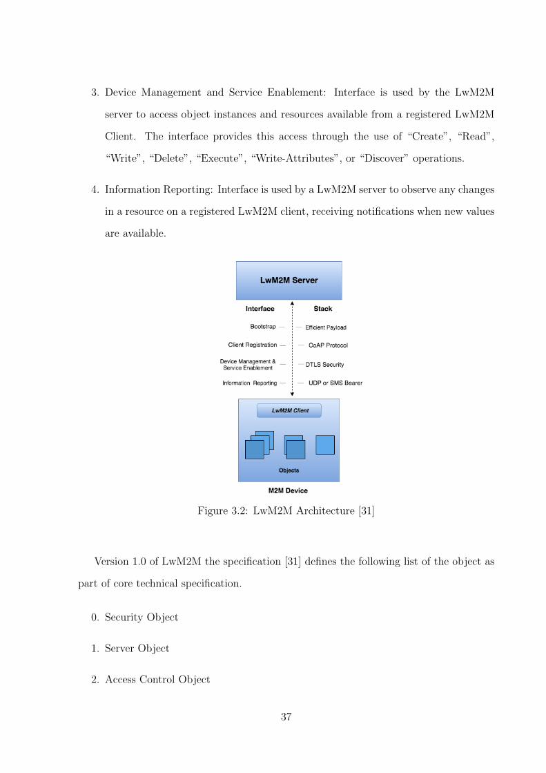
3. Device Management and Service Enablement: Interface is used by the LwM2M
server to access object instances and resources available from a registered LwM2M
Client. The interface provides this access through the use of “Create”, “Read”,
“Write”, “Delete”, “Execute”, “Write-Attributes”, or “Discover” operations.
4. Information Reporting: Interface is used by a LwM2M server to observe any changes
in a resource on a registered LwM2M client, receiving notifications when new values
are available.
Figure 3.2: LwM2M Architecture [31]
Version 1.0 of LwM2M the specification [31] defines the following list of the object as
part of core technical specification.
0. Security Object
1. Server Object
2. Access Control Object
37
3. Device Object
4. Connectivity Monitoring Object
5. Firmware Update Object
6. Location Object
7. Connectivity Statistics Object
3.3.1 LwM2M Firmware Upgrade Mechanism
Object 5 of LwM2M core technical specification enables firmware management on IoT
device. This Object includes installing firmware package, updating the firmware, and
performing actions after updating the firmware. The specification allows a version 1.0
complaint LwM2M client to connect with any LwM2M version 1.0 compliant server to
upgrade the firmware using the object and resource structure defined by the technical
specification. Table B.1 gives the details regarding LwM2M firmware object and its access
method. The firmware object further breaks down into the resources associated with it.
The specification [31] specifies nine resources related to firmware object. Table B.3 gives
a detailed explanation of firmware resource with the allowed values associated with it.
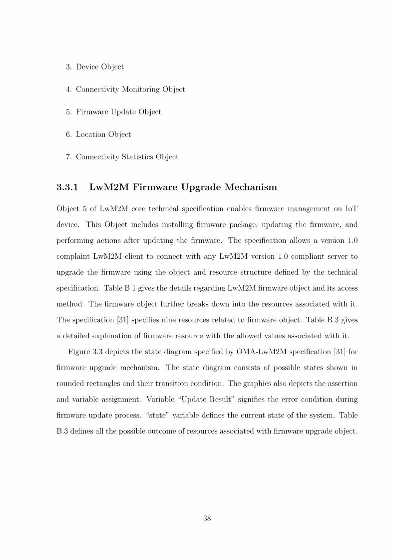
Figure 3.3 depicts the state diagram specified by OMA-LwM2M specification [31] for
firmware upgrade mechanism. The state diagram consists of possible states shown in
rounded rectangles and their transition condition. The graphics also depicts the assertion
and variable assignment. Variable “Update Result” signifies the error condition during
firmware update process. “state” variable defines the current state of the system. Table
B.3 defines all the possible outcome of resources associated with firmware upgrade object.
38
Figure 3.3: Firmware Update Mechanism [31].
State Diagram Walkthrough
Use Case #1: Successful Firmware Update
Initially, the STATE of the system remains IDLE and LwM2M server writes the
“Package URI” to IoT Device. IoT device establishes a connection with firmware
repository identified by URI provided by LwM2M server and starts downloading the
firmware image using CoAP block wise transfer. With the start of firmware download
STATE of the system should change to “DOWNLOADING”. The firmware download
will finish with the reception of the last block of firmware and at this point, the STATE
of the system should change to “DOWNLOADED”. The system will update the new
firmware upon the reception of “Update” resource from LwM2M server and STATE
should change to “UPDATE”. After the upgrade, the system should restart with new
39
firmware image and state of the system should change to “IDLE” and updates the result
with ‘1’ (Successfully update).
Use Case #2: Failed Firmware Update
Initially, the STATE of the system remains IDLE and LwM2M server writes the
“Package URI” to IoT Device. IoT device establishes a connection with firmware
repository identified by URI provided by LwM2M server and starts downloading the
firmware image using CoAP block wise transfer. With the start of firmware download
STATE of the system should change to “DOWNLOADING”. The firmware download
will finish with the reception of the last block of firmware and at this point, the STATE
of the system should change to “DOWNLOADED”. The system will update the new
firmware upon the reception of “Update” resource from LwM2M server and STATE
should change to “UPDATE”. The system will match the CRC received from the header
of firmware with the calculated CRC of the firmware image. In case of CRC mismatch,
the system will raise an assertion and update the “update result” with ‘5’ (Integrity
check failure).
The above discussion presented only one failure possibility. Similarly, in other failures,
the result will be updated with the type of failure given in OMA LwM2M specification
table B.3.
3.4 Firmware Transfer using CoAP Block Transfer
To avoid IP fragmentation, RFC-7959 [13] extends the specification of primary CoAP
with a pair of “Block” option to transfer multiple blocks of information from a resource
representation in multiple request-response pairs. Both the client and server have to
mutually agree on the size of the block to transfer. In general, CoAP block-wise transfer
is useful in case of firmware image transfer from firmware management server to IoT
device. OMA-LwM2M specification [31] mandates the use of CoAP block-wise transfer
to transport the firmware image.
40

Figure 3.4: Example of client fetching firmware image [31].
The figure 3.4 shows the transfer of firmware image using CoAP block-wise transfer in a
scenario where a package URI is provided to the client by LwM2M server and client
fetches the firmware image from indicated firmware management server. In the example
the both LwM2M client and server agreed on a block size of 128 bytes and the firmware
image of 80 KiB (=81920 bytes) sent to the LwM2M Client in 640 messages with each
128 bytes payload.
3.5 Firmware Validation
Once the new firmware is completely received in the system, it is essential to check its
validity. A faulty or erroneous firmware could make the system unusable after the
update. S. Unterschtz, et al. in his work [36] emphasis on the importance of fail-safe
over the air update and techniques to ensure system safety. In this implementation
below defined methods have been used to ensure validity and integrity of new firmware.
1. Cyclic redundancy check (CRC): Used to perform firmware validation. CRC is an
41

error detecting algorithm used to detect changes in raw data.
2. Firmware Size: This can be used to validate the integrity of firmware.
The firmware image is extended with the meta data header which contains the server
side calculated CRC value and Firmware image size. Once the firmware received at
device side, these values can be matched with the values calculated from the received
firmware. Figure 3.5 depicts the structure of final firmware with an extended header
containing CRC value and Firmware size.
Figure 3.5: Firmware image with extended header containing.
Firmware validation would take place in “DOWNLOADED” state of firmware update
state machine [31]. Any error in validation will be reported back to LwM2M server
using “update result” resource of firmware upgrade object.
3.6 Flash Operation and Bootloader
The previous sections explained firmware validation and transfer mechanism of a
firmware image from firmware management server to IoT device using CoAP block-wise
transfer. Upon the reception in an IoT device, firmware blocks could be stored in two
ways:
1. RAM Storage: The received blocks would be stored in RAM which is a volatile
but faster memory.
2. Flash Storage: The received blocks would be stored in flash memory which is a
nonvolatile but slower memory.
42
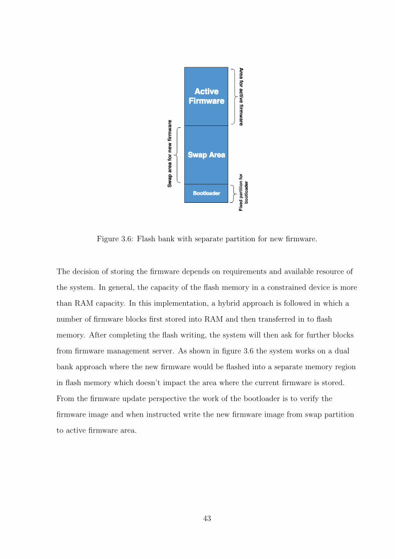
Figure 3.6: Flash bank with separate partition for new firmware.
The decision of storing the firmware depends on requirements and available resource of
the system. In general, the capacity of the flash memory in a constrained device is more
than RAM capacity. In this implementation, a hybrid approach is followed in which a
number of firmware blocks first stored into RAM and then transferred in to flash
memory. After completing the flash writing, the system will then ask for further blocks
from firmware management server. As shown in figure 3.6 the system works on a dual
bank approach where the new firmware would be flashed into a separate memory region
in flash memory which doesn’t impact the area where the current firmware is stored.
From the firmware update perspective the work of the bootloader is to verify the
firmware image and when instructed write the new firmware image from swap partition
to active firmware area.
43
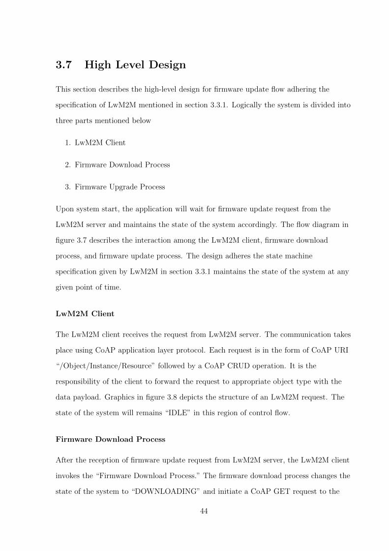
3.7 High Level Design
This section describes the high-level design for firmware update flow adhering the
specification of LwM2M mentioned in section 3.3.1. Logically the system is divided into
three parts mentioned below
1. LwM2M Client
2. Firmware Download Process
3. Firmware Upgrade Process
Upon system start, the application will wait for firmware update request from the
LwM2M server and maintains the state of the system accordingly. The flow diagram in
figure 3.7 describes the interaction among the LwM2M client, firmware download
process, and firmware update process. The design adheres the state machine
specification given by LwM2M in section 3.3.1 maintains the state of the system at any
given point of time.
LwM2M Client
The LwM2M client receives the request from LwM2M server. The communication takes
place using CoAP application layer protocol. Each request is in the form of CoAP URI
“/Object/Instance/Resource” followed by a CoAP CRUD operation. It is the
responsibility of the client to forward the request to appropriate object type with the
data payload. Graphics in figure 3.8 depicts the structure of an LwM2M request. The
state of the system will remains “IDLE” in this region of control flow.
Firmware Download Process
After the reception of firmware update request from LwM2M server, the LwM2M client
invokes the “Firmware Download Process.” The firmware download process changes the
state of the system to “DOWNLOADING” and initiate a CoAP GET request to the
44

Figure 3.7: High Level Software Design
45
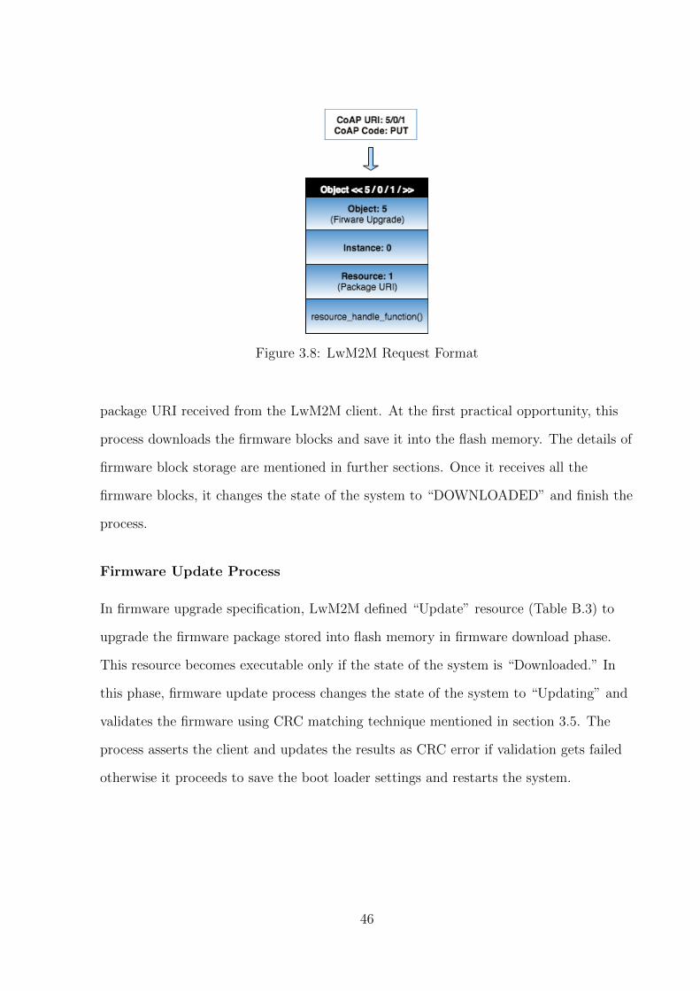
Figure 3.8: LwM2M Request Format
package URI received from the LwM2M client. At the first practical opportunity, this
process downloads the firmware blocks and save it into the flash memory. The details of
firmware block storage are mentioned in further sections. Once it receives all the
firmware blocks, it changes the state of the system to “DOWNLOADED” and finish the
process.
Firmware Update Process
In firmware upgrade specification, LwM2M defined “Update” resource (Table B.3) to
upgrade the firmware package stored into flash memory in firmware download phase.
This resource becomes executable only if the state of the system is “Downloaded.” In
this phase, firmware update process changes the state of the system to “Updating” and
validates the firmware using CRC matching technique mentioned in section 3.5. The
process asserts the client and updates the results as CRC error if validation gets failed
otherwise it proceeds to save the boot loader settings and restarts the system.
46
Chapter 4
Prototype Implementation and
Evaluation
4.1 Introduction
This chapter will provide a detail description of the firmware upgrade framework
implementation. It includes the discussion on hardware platform used, choice of software
platform along with the implementation of end to end firmware update software.
4.2 Requirement
4.2.1 Hardware Platform
Nordic Semiconductor nRF52 (nRF52832)
Nordic semiconductor’s nRF52 (nRF52832)1 is chosen as the hardware platform for this
prototype due to following reason.
1. Low-cost BLE device.
2. Support for IPv6 over BLE which is the core requirement of this dissertation
1https://www.nordicsemi.com/eng/Products/Bluetooth-low-energy/nRF52-DK
47
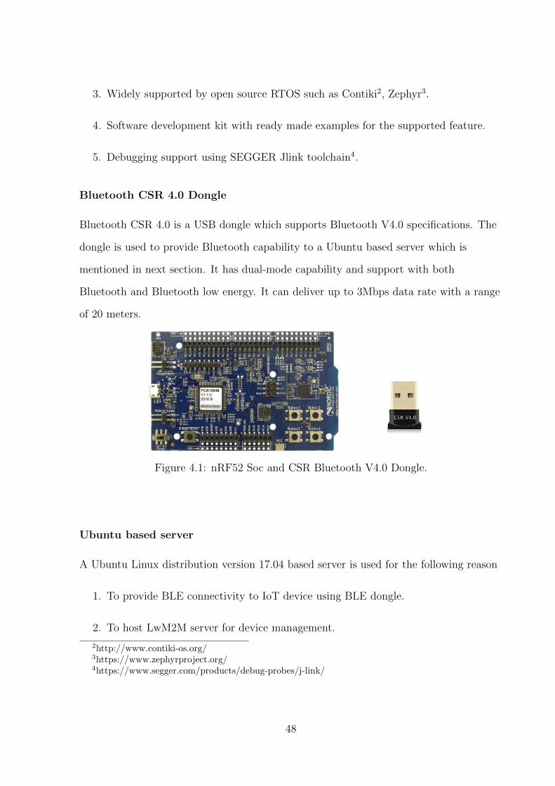
3. Widely supported by open source RTOS such as Contiki2, Zephyr3.
4. Software development kit with ready made examples for the supported feature.
5. Debugging support using SEGGER Jlink toolchain4.
Bluetooth CSR 4.0 Dongle
Bluetooth CSR 4.0 is a USB dongle which supports Bluetooth V4.0 specifications. The
dongle is used to provide Bluetooth capability to a Ubuntu based server which is
mentioned in next section. It has dual-mode capability and support with both
Bluetooth and Bluetooth low energy. It can deliver up to 3Mbps data rate with a range
of 20 meters.
Figure 4.1: nRF52 Soc and CSR Bluetooth V4.0 Dongle.
Ubuntu based server
A Ubuntu Linux distribution version 17.04 based server is used for the following reason
1. To provide BLE connectivity to IoT device using BLE dongle.
2. To host LwM2M server for device management.
2http://www.contiki-os.org/3https://www.zephyrproject.org/4https://www.segger.com/products/debug-probes/j-link/
48
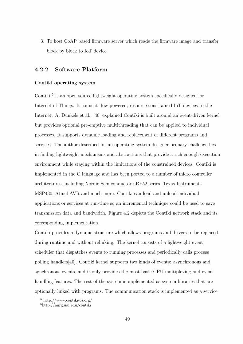
3. To host CoAP based firmware server which reads the firmware image and transfer
block by block to IoT device.
4.2.2 Software Platform
Contiki operating system
Contiki 5 is an open source lightweight operating system specifically designed for
Internet of Things. It connects low powered, resource constrained IoT devices to the
Internet. A. Dunkels et al., [40] explained Contiki is built around an event-driven kernel
but provides optional pre-emptive multithreading that can be applied to individual
processes. It supports dynamic loading and replacement of different programs and
services. The author described for an operating system designer primary challenge lies
in finding lightweight mechanisms and abstractions that provide a rich enough execution
environment while staying within the limitations of the constrained devices. Contiki is
implemented in the C language and has been ported to a number of micro controller
architectures, including Nordic Semiconductor nRF52 series, Texas Instruments
MSP430, Atmel AVR and much more. Contiki can load and unload individual
applications or services at run-time so an incremental technique could be used to save
transmission data and bandwidth. Figure 4.2 depicts the Contiki network stack and its
corresponding implementation.
Contiki provides a dynamic structure which allows programs and drivers to be replaced
during runtime and without relinking. The kernel consists of a lightweight event
scheduler that dispatches events to running processes and periodically calls process
polling handlers[40]. Contiki kernel supports two kinds of events: asynchronous and
synchronous events, and it only provides the most basic CPU multiplexing and event
handling features. The rest of the system is implemented as system libraries that are
optionally linked with programs. The communication stack is implemented as a service
5 http://www.contiki-os.org/6http://anrg.usc.edu/contiki
49
Figure 4.2: Contiki Network Stack.6
to enable run-time replacement.
Nordic IoT SDK
The nRF5 IoT SDK 7 is an IPv6 capable Bluetooth low energy software stacks that
enable nRF5 series devices to connect and communicate directly to cloud services and
other devices over the IP-based network using Bluetooth low energy. It includes an IPv6
over Bluetooth low energy adaptation layer (6LoWPAN) and a complete Internet
Protocol Suite including IPv6, ICMP, UDP, TCP, DTLS, TLS, CoAP, and MQTT. It
provides the support of required features in the form of drivers, libraries, examples, and
APIs which makes it general purpose tool for getting started with IoT. IPv6 addresses
are assigned to all IoT devices, and the BLE link is used to transmit the IPv6 packages.
The graphic in figure 4.3 shows the IoT devices that are connected to the Internet
through BLE enabled router.
7 https://www.nordicsemi.com/eng/Products/Bluetooth-low-energy/nRF5-SDK-for-IoT
50

Figure 4.3: BLE enabled IoT Network.8
The SDK also included various examples for configuring nR52 devices as a Bluetooth
low energy 6LoWPAN node and configuring it with the above transport layer (UDP and
TCP) with security (DTLS and TLS), to the application layer CoAP, MQTT, and
LwM2M. Figure 4.4 depicts the protocol stack of Nordic IoT SDK which is required to
route IPv6 packets to and from IoT devices.
Figure 4.4: Protocol stack of Nordic IoT SDK.footnotemark[8]
SoftDevices are precompiled, pre-linked libraries that can be programmed into Nordic
nRF series devices. It is an abstraction layer for the BLE radio and lets the application
integrate with lower layer radio technology. The SoftDevice provide the facility to
develop application code as ARM Cortex-M0 project and access the toolchain of ARM
8 http://infocenter.nordicsemi.com
51
Cortex-M0 for application development. The examples given in NRF IoT SDK requires
a modified SoftDevice. “S1xx iot”9 supports L2CAP Connection Oriented Channels,
which is needed for transport of IP packets.
The APIs exposed by SoftDevice is composed of C function which makes the application
completely independent of compiler and linker8. The APIs are based on SuperVisor
Calls (SVC) and defined in a set of a header file. In ARM architecture SVCs are
software triggered interrupts and in Nordic’s implementation SVCs conforms to a
standard procedure call and allows parameter passing and return values. By calling a
Softdevice API, triggers an SVC interrupt which in turn calls the SVC interrupt
handler. The application compiles without any function address information at compile
time and this removes the application linking dependency with the SoftDevice. The
header files contain all information required for the application to invoke the API
functions. This SVC interface makes SoftDevice API calls thread-safe.
ARM GNU Toolchain
The GNU Embedded Toolchain 10 for ARM is a collection of packages featuring ARM
Embedded GCC compiler, binutils, GNU debugger (GDB) and other GNU libraries
necessary for bare-metal software development. It is a ready-to-use, open source suite of
tools for C, C++, and Assembly programming targeting devices based on the ARM
Cortex-M and Cortex-R processors. Based on Free Software Foundation’s (FSF) GNU
Open source tools and newlib, these toolchains are available for cross-compilation on
Microsoft Windows, Linux and Mac OS X host operating systems.
The toolchains support code generation for non-OS or ’bare-metal’ environments. It
supports ARM Cortex-M0, Cortex-M0+, Cortex-M3, Cortex-M4, Cortex-M7,
Cortex-R4, Cortex-R5, Cortex-R7, Cortex-R8 processors and ARMv8-M baseline and
mainline architectures.
9nRF5 IoT SDK v. 0.9.0 Release Notes10https://developer.arm.com/open-source/gnu-toolchain/
52

Leshan (OMA Lightweight M2M server)
Leshan is an open source OMA Lightweight Machine to Machine (LwM2M) java client
and server implementation11. It provides libraries to develop an LwM2M client and
server using the Java programming language. Leshan project contains a client, a server,
and a bootstrap server as an example to demonstrate Leshan APIs and for testing
purpose. Below mentioned are some of the salient features of Leshan
• Eclipse project since 2014
• Modular Java libraries
• Based on Californium CoAP implementation
• Based on Scandium DTLS implementation
• IPSO objects support
As shown in the figure 4.5, Leshan provides a very simple UI to get the list of connected
clients and interact with clients resources.
11http://www.eclipse.org/leshan/
53

Figure 4.5: UI of Leshan Server shows interaction with NRF device.
4.3 Software Setup and Configurations
Connecting Devices to the Router
Ubuntu version 17.04 has a pre-compiled 6LoWPAN module. To establish a connection
between an nRF52 device and Linux router following procedure need to follow.
# Log in as a root user.
$ sudo su
# Mount debugfs file system.
$ mount -t debugfs none /sys/kernel/debug
# Load 6LoWPAN module.
$ modprobe bluetooth_6lowpan
54

# Enable the bluetooth 6lowpan module.
$ echo 1 > /sys/kernel/debug/bluetooth/6lowpan_enable
# Look for available HCI devices.
$ hciconfig
# Reset HCI device - for example hci0 device.
$ hciconfig hci0 reset
# Read 00:AA:BB:XX:YY:ZZ address of the nRF5x device.
$ hcitool lescan
# Connect to the device.
$ echo "connect 00:AA:BB:XX:YY:ZZ 1" >
/sys/kernel/debug/bluetooth/6lowpan_control
# Check if you have established a connection.
$ ifconfig
# Try to ping the device using its link-local address,
for example, on bt0 interface.
$ ping6 -i bt0 fe80::2aa:bbff:fexx:yyzz
# Disconnect from the device.
$ echo "disconnect 00:AA:BB:XX:YY:ZZ" >
/sys/kernel/debug/bluetooth/6lowpan_control
# Check if there are active connections left.
$ ifconfig
Creating Link-Local IPv6 addresses
A link local IPv6 address must be assigned to a device to identify it uniquely in the
network. This address is based on the interface identifier (IID), which derives from the
Bluetooth Device address. Link-local addresses contain the prefix FE80::/10 and a 64-bit
55

interface identifier (IID) [16]. Link-local addresses are used for addressing on a single
link if no router present in the network or the case of automatic address configuration.
Creating an IPv6 link-local address comprises three steps:
1. Transforming the Bluetooth device address into Modified EUI-64 format
2. Transforming the Modified EUI-64 address into an IID
3. Transforming the IID into a link-local address
For example, link-local address for the Bluetooth device address C0:11:22:33:44:55 is
FE80:0000:0000:0000:C011:22FF:FE33:4455, or simpler FE80::C011:22FF:FE33:4455.
Global IPv6 Prefix Distribution
By using a link-local source or destination address, routers are not allowed to forward
any packets to other links. It is required to distribute a global IPv6 prefix to the
connected devices to expose Bluetooth devices outside the link-local network. For this
purpose, Router Advertisement Daemon (RADVD) can be used on Linux. RADVD can
periodically or on solicitation send a Router Advertisement message. There are two
ways of obtaining global IPv6 prefix.
1. Stateful auto-configuration (using DHCPv6).
2. Stateless auto-configuration.
The figure illustrates how an IPv6 global address is constructed using stateless 4.6
auto-configuration.
RADVD Configuration as follows:
# Set IPv6 forwarding (must be present).
$ sudo echo 1 > /proc/sys/net/ipv6/conf/all/forwarding
56

Figure 4.6: IPv6 Stateless Auto-Configuration.8
# Run radvd daemon.
$ sudo service radvd restart
# Assign prefix to btX interface
$ sudo ifconfig btX add 2001:db8::1/64
Leshan Server Initialization
The Leshan bootstrap and LwM2M standalone server have to be compiled from source
code. After compilation libraries and example server would be ready to use. Following
commands will execute Leshan bootstrap and LwM2M server.
# Multiplex port
$ ifconfig bt0 add 2001:db8::1/64
$ ifconfig bt0 add 2001:db8::2/64
57

# Execute Leshan LwM2M server
$ java -jar leshan-server-demo/target/leshan-server-demo-*-SNAPSHOT
-jar-with-dependencies.jar --coaphost 2001:db8::1 --coapport 5683
# Execute Leshan bootstrap server
$ java -jar leshan-server-demo/target/leshan-server-demo-*-SNAPSHOT
-jar-with-dependencies.jar --coaphost 2001:db8::1 --coapport 5683
4.4 Software Implementation and Interaction
Figure 4.7 depicts the interaction between the components of the system. The
interaction is logically divided into five parts and described in further sections.
1. Initialization phase
2. Firmware Update Request
3. Firmware Download phase
4. Firmware Update phase
5. Firmware Swap phase
58
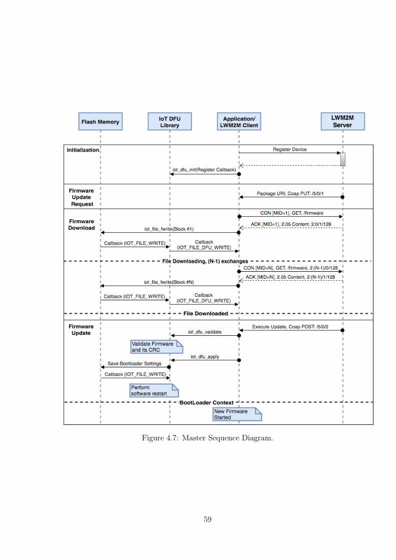
Figure 4.7: Master Sequence Diagram.
59
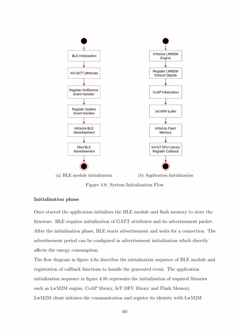
(a) BLE module initialization (b) Application Initialization
Figure 4.8: System Initialization Flow
Initialization phase
Once started the application initializes the BLE module and flash memory to store the
firmware. BLE requires initialization of GATT attributes and its advertisement packet.
After the initialization phase, BLE starts advertisement and waits for a connection. The
advertisement period can be configured in advertisement initialization which directly
affects the energy consumption.
The flow diagram in figure 4.8a describes the initialization sequence of BLE module and
registration of callback functions to handle the generated event. The application
initialization sequence in figure 4.8b represents the initialization of required libraries
such as LwM2M engine, CoAP library, IoT DFU library and Flash Memory.
LwM2M client initiates the communication and register its identity with LwM2M
60
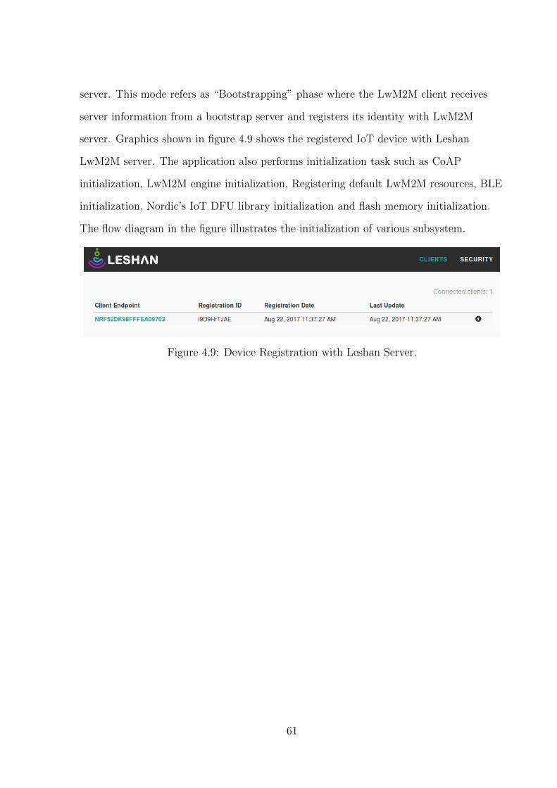
server. This mode refers as “Bootstrapping” phase where the LwM2M client receives
server information from a bootstrap server and registers its identity with LwM2M
server. Graphics shown in figure 4.9 shows the registered IoT device with Leshan
LwM2M server. The application also performs initialization task such as CoAP
initialization, LwM2M engine initialization, Registering default LwM2M resources, BLE
initialization, Nordic’s IoT DFU library initialization and flash memory initialization.
The flow diagram in the figure illustrates the initialization of various subsystem.
Figure 4.9: Device Registration with Leshan Server.
61

Firmware Update Request
The user can issue a firmware update request using the “Package URI” object of
LwM2M firmware resource. Package URI will generate a CoAP “POST” request and
provides the URI of firmware to the application. With the next practical opportunity the
CoAP server issues CoAP “GET” request to block-wise download the package into the
system. More details on LwM2M firmware resource can be found in table B.3. Graphics
in figures 4.10 shows the UI of Leshan LwM2M server with firmware update object.
Figure 4.10: Firmware Update UI of Leshan Server
Firmware Download phase
CoAP blockwise transfer is used for transporting the firmware from firmware
management server to IoT device. Section 3.4 explains the mechanism of CoAP block
transfer where both server and client mutually agree on the size of the block to transfer
and client initiates the transfer process. Wireshark12 logs in figure 4.11 signifies the
transfer of CoAP blocks from firmware management server to IoT device.
Upon reception of firmware block, it needs to be written into flash memory. As
illustrated in figure 4.12, in this implementation a number of blocks first collected into
RAM buffer and then written into flash memory. Writing of firmware blocks into flash
memory is implemented using the “IoT File” library provided by Nordic
12https://www.wireshark.org/
62

Figure 4.11: CoAP block transfer messages in wireshark
semiconductor8. IoT file abstraction library provides the APIs for accessing any object,
which can be treated as a file. Applications can use the APIs provided by libraries for
read and write operations to the memory block. The provided APIs are implemented in
an asynchronous fashion and to support that the library defines the event structure
where an application callback is assigned in the initialization phase of specified file
instance. The callback notifies the application when the data is ready, or operation is
completed which in turns could be useful to unlock another procedure. Message passing
using events and callbacks is shown in the “firmware download” and “firmware update”
phase of figure 4.7
In the SoftDevice implementation provided by the Nordic semiconductor, the underlying
flash operations are performed using the SoC library API. The flash memory access is
scheduled by SoftDevice in between the protocol radio events8. The flash access time
could be larger with short connection or advertisement intervals. The access may also be
slightly delayed to minimize the disturbance of the BLE radio protocol. In some case,
the flash memory access may fail with a timeout event:
NRF EVT FLASH OPERATION ERROR.
Firmware Update phase
The importance of firmware validation is mentioned in section 3.5. Firmware validation
is implemented using the “IoT DFU” library provided by Nordic semiconductor8. IoT
DFU exposes a common API for configuration and checksum validation. The library is
63
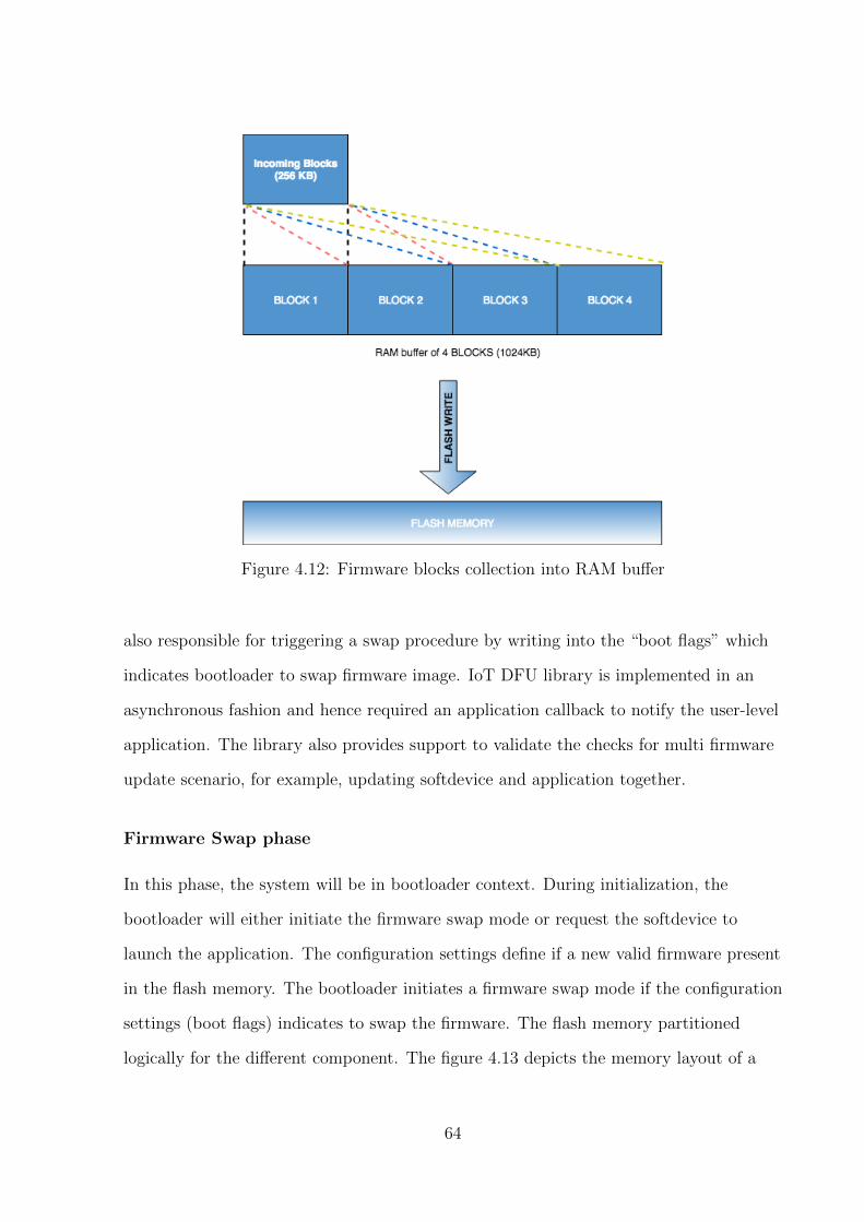
Figure 4.12: Firmware blocks collection into RAM buffer
also responsible for triggering a swap procedure by writing into the “boot flags” which
indicates bootloader to swap firmware image. IoT DFU library is implemented in an
asynchronous fashion and hence required an application callback to notify the user-level
application. The library also provides support to validate the checks for multi firmware
update scenario, for example, updating softdevice and application together.
Firmware Swap phase
In this phase, the system will be in bootloader context. During initialization, the
bootloader will either initiate the firmware swap mode or request the softdevice to
launch the application. The configuration settings define if a new valid firmware present
in the flash memory. The bootloader initiates a firmware swap mode if the configuration
settings (boot flags) indicates to swap the firmware. The flash memory partitioned
logically for the different component. The figure 4.13 depicts the memory layout of a
64

512kB nrf52 device.
Figure 4.13: Flash Memory Layout of a 512kB nrf52 device.8
65
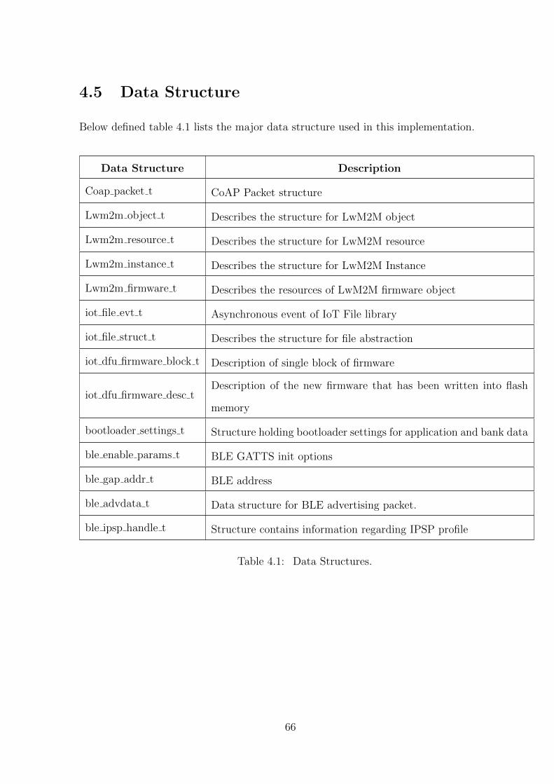
4.5 Data Structure
Below defined table 4.1 lists the major data structure used in this implementation.
Data Structure Description
Coap packet t CoAP Packet structure
Lwm2m object t Describes the structure for LwM2M object
Lwm2m resource t Describes the structure for LwM2M resource
Lwm2m instance t Describes the structure for LwM2M Instance
Lwm2m firmware t Describes the resources of LwM2M firmware object
iot file evt t Asynchronous event of IoT File library
iot file struct t Describes the structure for file abstraction
iot dfu firmware block t Description of single block of firmware
iot dfu firmware desc tDescription of the new firmware that has been written into flash
memory
bootloader settings t Structure holding bootloader settings for application and bank data
ble enable params t BLE GATTS init options
ble gap addr t BLE address
ble advdata t Data structure for BLE advertising packet.
ble ipsp handle t Structure contains information regarding IPSP profile
Table 4.1: Data Structures.
66
4.6 Evaluation
4.6.1 Firmware Download and Firmware Update
Objective
This experiment is a qualitative analysis to evaluate the functional requirement of the
implementation. The test issues the firmware download and update commands from
LwM2M server and assess the state of the system and update result.
Methodology
1. Configure the software and related services as mentioned in section 4.3.
2. Access Leshan server UI and check the firmware version and state of the system.
3. provide “package URI” and check the state of the system.
4. The system state should change after the package download.
5. Execute update and check the firmware version after device reboot.
Results
The results are measured and mentioned below for each given test case in section 4.6.1.
1. Initially Firmware version was “NRF OTA V1.0, ” and state of the system was
“IDLE.”
2. After providing the “package URI,” the state of the system was changed to
“DOWNLOADING.”
3. After package download, the system state was changed to “DOWNLOADED.”
4. After execution of update device rebooted and firmware version changed to
“NRF OTA V2.0.”
67
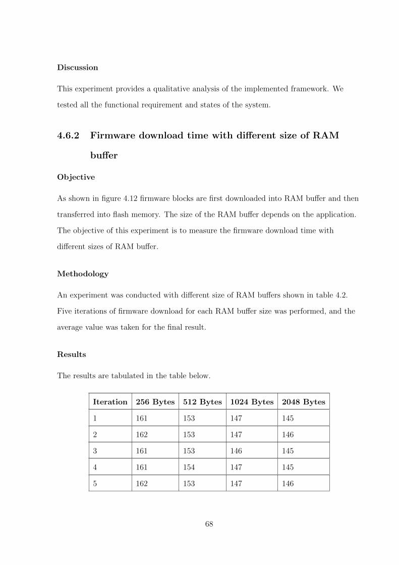
Discussion
This experiment provides a qualitative analysis of the implemented framework. We
tested all the functional requirement and states of the system.
4.6.2 Firmware download time with different size of RAM
buffer
Objective
As shown in figure 4.12 firmware blocks are first downloaded into RAM buffer and then
transferred into flash memory. The size of the RAM buffer depends on the application.
The objective of this experiment is to measure the firmware download time with
different sizes of RAM buffer.
Methodology
An experiment was conducted with different size of RAM buffers shown in table 4.2.
Five iterations of firmware download for each RAM buffer size was performed, and the
average value was taken for the final result.
Results
The results are tabulated in the table below.
Iteration 256 Bytes 512 Bytes 1024 Bytes 2048 Bytes
1 161 153 147 145
2 162 153 147 146
3 161 153 146 145
4 161 154 147 145
5 162 153 147 146
68
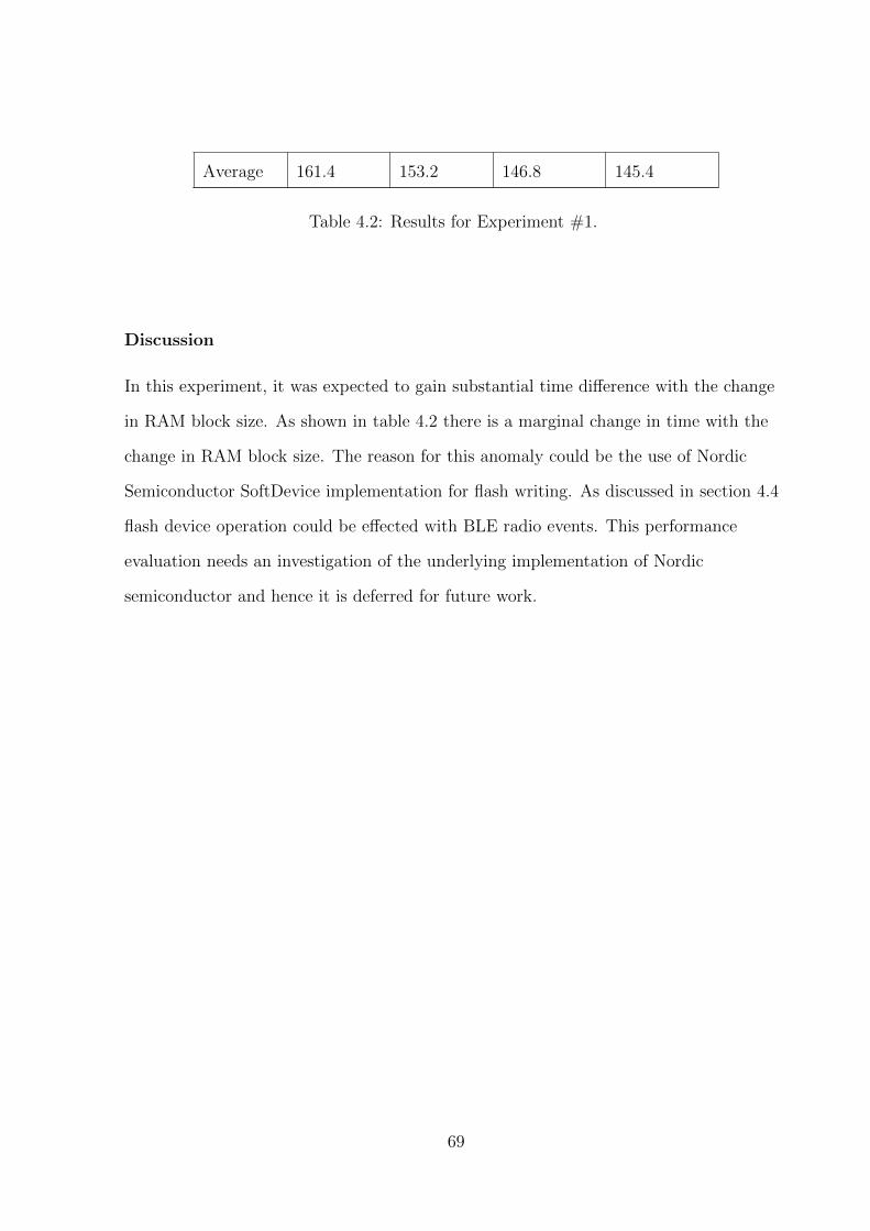
Average 161.4 153.2 146.8 145.4
Table 4.2: Results for Experiment #1.
Discussion
In this experiment, it was expected to gain substantial time difference with the change
in RAM block size. As shown in table 4.2 there is a marginal change in time with the
change in RAM block size. The reason for this anomaly could be the use of Nordic
Semiconductor SoftDevice implementation for flash writing. As discussed in section 4.4
flash device operation could be effected with BLE radio events. This performance
evaluation needs an investigation of the underlying implementation of Nordic
semiconductor and hence it is deferred for future work.
69
Chapter 5
Conclusion and Future Work
5.1 Introduction
We identified the gaps in the current state of the art for firmware update and proposed
the design for an end to and firmware solution adhering to specified standards. Further,
we implemented a working prototype of the proposed design and evaluated the
implementation. The final chapter concludes the dissertation by highlighting the
features of the implementation, challenges faced during the implementation and future
work that can be done.
5.2 Prototype
This dissertation presents a working prototype of an end to end firmware upgrade
framework which adheres the standard specifications. The prototype provides the
implementation of firmware upgrade state machine specified by OMA LwM2M [31]. The
prototype was tested with a number of different new firmware images to upgrade and it
was concluded that the approach is successfully allowing the new firmware upgrade on a
BLE device and also presenting the state of the system at any given point of time.
70
5.3 Contributions
In this dissertation, we established state of the art for current IoT standards and
specifications. Further, we identified the gaps in the current firmware update solution.
We addressed these deficiencies by implemented an end to end solution for the firmware
upgrade on a BLE device using IPv6 over BLE which adheres the current standards.
The implementation is ready for an open source contribution. Below mentioned are the
novel contributions of this dissertation.
1. Coding and implementation for LwM2M firmware state machine.
2. Coding and implementation CoAP block transfer client in IoT device.
3. Integration of Nordic IoT DFU library with open source Contiki RTOS.
5.4 Challenges
1. The code base involved two different SDKs, Nordic IoT SDK7 and Contiki
operating system5. Integration of Nordic’s IoT DFU libraries with Contiki SDK
became a problem. Each relevant code file was manually selected and added into
Contiki code base.
2. Support for NRF52 DK in the current version of Contiki is broken. The issue is
already reported, but no action is taken yet. This dissertation is implemented
using the previous version of Contiki in which NRF52 DK is supported.
3. Less documentation regarding the flash usage of nrf52 DK causes the loss of time
while integrating flash writing support to Contiki OS.
4. Testing and debugging on actual hardware was time-consuming. For debugging
purpose, most of the time we had to rely on message prints on the serial terminal.
5. Reading and understanding the specification was time-consuming.
71
5.5 Future Work
5.5.1 Energy Efficient Updates
Energy is a major constraint in IoT devices. In general updating, a firmware means
pushing a fix or new feature into the device. A major part of the firmware remains
same. In this implementation, we are sending a new firmware with every update which
required more energy with every update. Approaches like incremental or modular
Updates could be used for an energy efficient firmware upgrade. These methods reduce
the traffic load by sending only a part of firmware to upgrade; as a result less energy
consumption. In section 2.5 we mentioned few approaches which follow an incremental
or modular update fashion. In future, these approaches could be integrated with current
prototype to make it more robust and energy efficient solution.
Incremental Update
In incremental update approach, a compressed incremental patch could be sent in the
existing system. This would reduce the bandwidth usage as compared to image based
update. To generate the delta (change of old and new firmware) a number of techniques
are available namely, RDIFF, VCDIFF, and BSDIFF. The delta can be compressed on
the server side using Lempel-Ziv (LZ) variant of data compression algorithm. Upon
reception of delta on IoT device, it can be decompressed and patched with the active
firmware updates. The required downtown of the system would depend on the
application of the system and method of patching. At present Zephyr1 supports
incremental updates and development is on going for IPv6 support over BLE. Zephyr
could be a potential platform to work with to support incremental update. However,
from device management side, specification given by LwM2M supports only image based
update. It would be challenging to handle an end to end upgrade for a single patch of
firmware.
1https://www.zephyrproject.org/
72

Modular Update
In a Modular update, the OS should support the dynamic linking and instantiation of
modules. Contiki is one such platform which supports dynamic module loading. Again
in this solution, the challenge would be from device management side, specification
given by LwM2M supports only image based update. It would be challenging to handle
an end to end upgrade for a single module of the system.
5.5.2 Firmware Upgrade in a mesh network
In December 2016, Bluetooth SIG released the specification for Bluetooth V5.02.
Bluetooth V5.0 adopted the mesh topology which allows devices to become a hub and
communicating directly or indirectly with other devices. In this dissertation, the current
firmware upgrade prototype is focused on a peer to peer firmware upgrade. The mesh
support of Bluetooth V5.0 could be used to extend this prototype and allowing the
firmware upgrades on peer nodes using the IoT device in picture as a hub.
As described in section 1.2 the traditional communication paradigm of client/server
model is not appropriate for IoT. In mesh network nodes can communicate with each
other and from firmware upgrade prospective neighboring nodes can fetch latest
firmware from its peer nodes. This will eliminate the single point of failure possibility
and introduce resiliency in the network.
5.5.3 Security implication of firmware upgrade
Security is an open area of research in the domain of Internet of things. There are
vulnerabilities exposed in each layer of IoT ecosystem. In case of firmware upgrades
security needs to be implemented from firmware management server till the IoT device.
The report provided by S.Farell et al.,3 mentions a large number of concerns when it
2https://www.bluetooth.com/specifications/bluetooth-core-specification3https://tools.ietf.org/html/draft-farrell-iotsu-workshop-00
73

comes to securing the ecosystem. This dissertation could further be extended to address
the security concerns and provide a “secure end to end firmware upgrade framework.”
5.5.4 Performance Evaluation
We performed the performance evaluation in section 4.6.2. Further investigation is
required to identify the cause of anomaly caused in download time with the different size
of firmware blocks. One such indication is the interference of SoftDevice with flash
writing while ongoing radio event. This could be further analyzed with the good
knowledge of Nordic’s SoftDevice implementation.
5.6 Conclusion
The aim of implementing a standard compliant, end to end firmware upgrade solution
on a BLE device using IPv6 over BLE was successfully achieved using Nordic NRF52
platform and support provided by Contiki operating system. To the best of the writers
knowledge, this is the first time such an approach where an inter operable solution for
firmware upgrade in IoT device had been implemented.
The framework and its further extension would provide a solution for long running
problems in IoT ecosystem to manage and upgrading a fleet of devices. The
specification followed by this framework would make it inter operable and extend its
reach to work with different vendors and services. This approach is a one step forward
to envisage the Internet of Things.
74
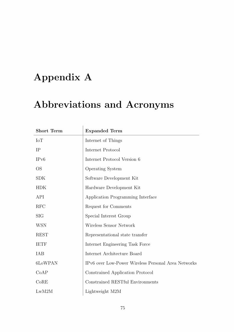
Appendix A
Abbreviations and Acronyms
Short Term Expanded Term
IoT Internet of Things
IP Internet Protocol
IPv6 Internet Protocol Version 6
OS Operating System
SDK Software Development Kit
HDK Hardware Development Kit
API Application Programming Interface
RFC Request for Comments
SIG Special Interest Group
WSN Wireless Sensor Network
REST Representational state transfer
IETF Internet Engineering Task Force
IAB Internet Architecture Board
6LoWPAN IPv6 over Low-Power Wireless Personal Area Networks
CoAP Constrained Application Protocol
CoRE Constrained RESTful Environments
LwM2M Lightweight M2M
75
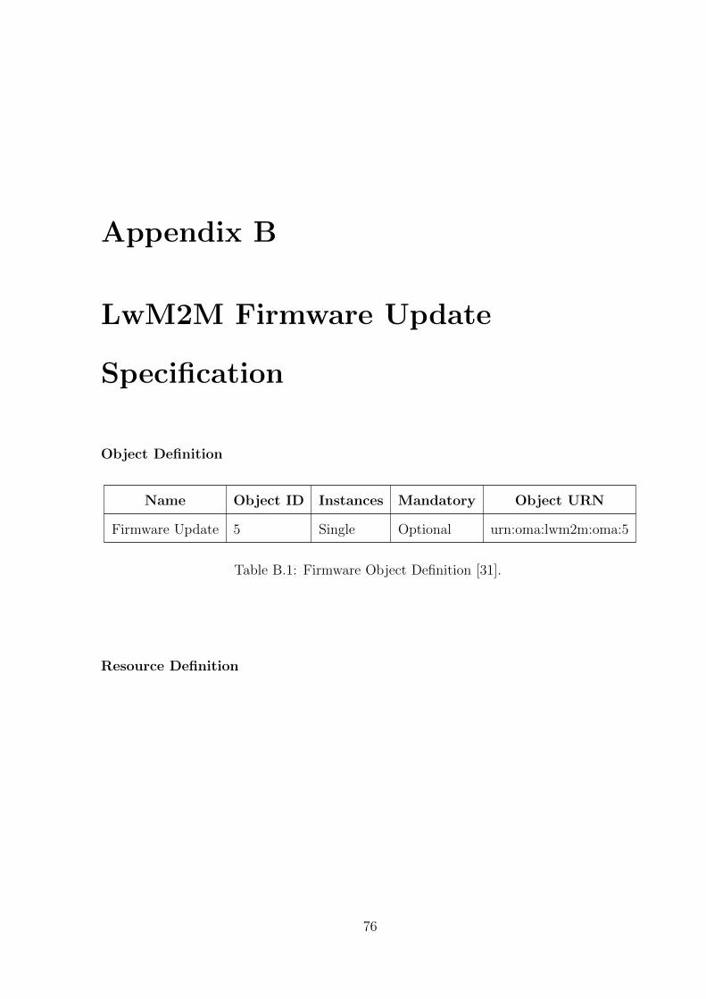
Appendix B
LwM2M Firmware Update
Specification
Object Definition
Name Object ID Instances Mandatory Object URN
Firmware Update 5 Single Optional urn:oma:lwm2m:oma:5
Table B.1: Firmware Object Definition [31].
Resource Definition
76
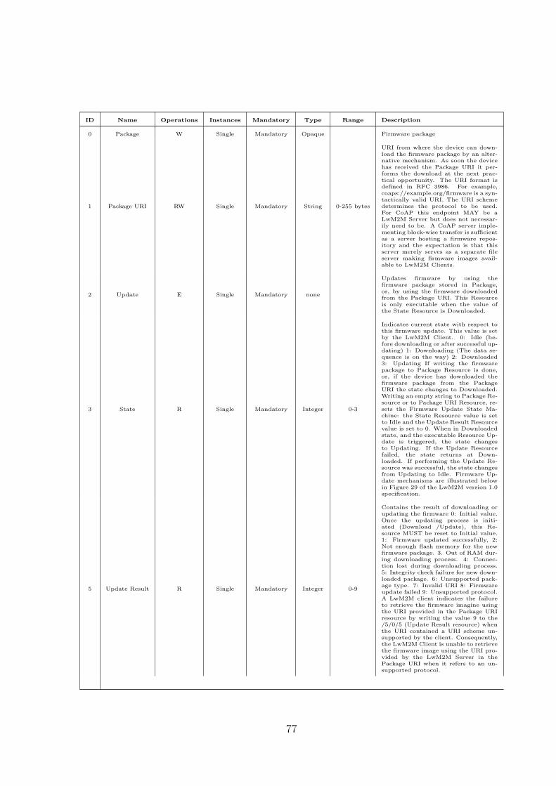
ID Name Operations Instances Mandatory Type Range Description
0 Package W Single Mandatory Opaque Firmware package
1 Package URI RW Single Mandatory String 0-255 bytes
URI from where the device can down-load the firmware package by an alter-native mechanism. As soon the devicehas received the Package URI it per-forms the download at the next prac-tical opportunity. The URI format isdefined in RFC 3986. For example,coaps://example.org/firmware is a syn-tactically valid URI. The URI schemedetermines the protocol to be used.For CoAP this endpoint MAY be aLwM2M Server but does not necessar-ily need to be. A CoAP server imple-menting block-wise transfer is sufficientas a server hosting a firmware repos-itory and the expectation is that thisserver merely serves as a separate fileserver making firmware images avail-able to LwM2M Clients.
2 Update E Single Mandatory none
Updates firmware by using thefirmware package stored in Package,or, by using the firmware downloadedfrom the Package URI. This Resourceis only executable when the value ofthe State Resource is Downloaded.
3 State R Single Mandatory Integer 0-3
Indicates current state with respect tothis firmware update. This value is setby the LwM2M Client. 0: Idle (be-fore downloading or after successful up-dating) 1: Downloading (The data se-quence is on the way) 2: Downloaded3: Updating If writing the firmwarepackage to Package Resource is done,or, if the device has downloaded thefirmware package from the PackageURI the state changes to Downloaded.Writing an empty string to Package Re-source or to Package URI Resource, re-sets the Firmware Update State Ma-chine: the State Resource value is setto Idle and the Update Result Resourcevalue is set to 0. When in Downloadedstate, and the executable Resource Up-date is triggered, the state changesto Updating. If the Update Resourcefailed, the state returns at Down-loaded. If performing the Update Re-source was successful, the state changesfrom Updating to Idle. Firmware Up-date mechanisms are illustrated belowin Figure 29 of the LwM2M version 1.0specification.
5 Update Result R Single Mandatory Integer 0-9
Contains the result of downloading orupdating the firmware 0: Initial value.Once the updating process is initi-ated (Download /Update), this Re-source MUST be reset to Initial value.1: Firmware updated successfully, 2:Not enough flash memory for the newfirmware package. 3. Out of RAM dur-ing downloading process. 4: Connec-tion lost during downloading process.5: Integrity check failure for new down-loaded package. 6: Unsupported pack-age type. 7: Invalid URI 8: Firmwareupdate failed 9: Unsupported protocol.A LwM2M client indicates the failureto retrieve the firmware imagine usingthe URI provided in the Package URIresource by writing the value 9 to the/5/0/5 (Update Result resource) whenthe URI contained a URI scheme un-supported by the client. Consequently,the LwM2M Client is unable to retrievethe firmware image using the URI pro-vided by the LwM2M Server in thePackage URI when it refers to an un-supported protocol.
77

ID Name Operations Instances Mandatory Type Range Description
6 PkgName R Single Optional String 0-255 bytes Name of the Firmware Package
7 PkgVersion R Single Optional String 0-255 bytes Version of the Firmware package
8 Protocol Support R Multiple Optional Integer
This resource indicates what proto-cols the LwM2M Client implementsto retrieve firmware images. TheLwM2M server uses this informationto decide what URI to include inthe Package URI. A LwM2M ServerMUST NOT include a URI in thePackage URI object that uses a pro-tocol that is unsupported by theLwM2M client. For example, ifa LwM2M client indicates that itsupports CoAP and CoAPS then aLwM2M Server must not providean HTTP URI in the Packet URI.The following values are defined bythis version of the specification: 0CoAP (as defined in RFC 7252) withthe additional support for block-wisetransfer. CoAP is the default set-ting. 1 CoAPS (as defined in RFC7252) with the additional support forblock-wise transfer 2 HTTP 1.1 (asdefined in RFC 7230) 3 HTTPS1.1 (as defined in RFC 7230) Addi-tional values MAY be defined in thefuture. Any value not understoodby the LwM2M Server MUST be ig-nored.
9 Delivery Method R Single Mandatory Integer
The LwM2M Client uses this re-source to indicate its support fortransferring firmware images to theclient either via the Package Re-source (=push) or via the PackageURI Resource (=pull) mechanism. 0Pull only 1 Push only 2 Both. Inthis case the LwM2M server MAYchoose the preferred mechanism forconveying the firmware image to theLwM2M Client.
Table B.3: Firmware Resource Definition [31].
78

Bibliography
[1] “Internet of Things: Science Fiction or Business Fact?” Harvard Business
Review. November 2014.
[2] H. Ching-Wen, Y. Ching-Chiang, “Understanding the factors affecting the
adoption of the Internet of Things,” Technology Analysis & Strategic
Management, 2016, pp. 1-14.
[3] I. Florea, R. Rughinis, L. Ruse and D. Dragomir, “Survey of Standardized
Protocols for the Internet of Things,” 21st International Conference on Control
Systems and Computer Science (CSCS), Bucharest, 2017, pp. 190-196.
[4] S. Nalbandian, “A survey on Internet of Things: Applications and challenges,”
International Congress on Technology, Communication and Knowledge
(ICTCK), Mashhad, 2015, pp. 165-169.
[5] Tschofenig H., et. al., “Architectural Considerations in Smart Object
Networking,” Tech. no. RFC 7452, Internet Architecture Board, Mar. 2015.
Web. https://www.rfc-editor.org/rfc/rfc7452.txt
[6] D. Hardt et. al., “The OAuth 2.0 Authorization Framework,” Tech. no. RFC
6749, Internet Engineering Task Force, Oct. 2012. Web.
https://tools.ietf.org/html/rfc6749
[7] T. Bray et. al., “The JavaScript Object Notation (JSON) Data Interchange
79
Format,” Tech. no. RFC 7159, Internet Engineering Task Force, Mar. 2014.
Web. https://tools.ietf.org/html/rfc7159
[8] C. Bormann et. al., “Concise Binary Object Representation (CBOR)”, Tech. no.
RFC 7049, Internet Engineering Task Force, Oct. 2013. Web.
https://tools.ietf.org/html/rfc7049
[9] Jaime Jimenez et. al, “IPSO Smart Objects,” in IoT Semantic Interoperability
Workshop, San Jose, US, Mar 2016.
[10] M. B. Yassein, M. Q. Shatnawi and D. Al-zoubi, “Application layer protocols for
the Internet of Things: A survey,” 2016 International Conference on Engineering
& MIS (ICEMIS), Agadir, 2016, pp. 1-4.
[11] C. Bormann, A. P. Castellani and Z. Shelby, “CoAP: An Application Protocol
for Billions of Tiny Internet Nodes,” in IEEE Internet Computing, vol. 16, no. 2,
pp. 62-67, March-April 2012.
[12] Z. Shelby et. al., “The Constrained Application Protocol (CoAP),” Tech. no.
RFC 7252, Internet Engineering Task Force, Jun. 2014. Web.
https://tools.ietf.org/html/rfc7252
[13] C. Bormann et. al., “Block-Wise Transfers in the Constrained Application
Protocol (CoAP),” Tech. no. RFC 7959, Internet Engineering Task Force, Aug.
2016. Web. https://tools.ietf.org/html/rfc7959
[14] S. Deering et. al., “Internet Protocol, Version 6 (IPv6) Specification,” Tech. no.
RFC 2460, Internet Engineering Task Force, Dec. 1998. Web.
https://tools.ietf.org/html/rfc2460
[15] S. Deering et. al., “Internet Protocol, Version 6 (IPv6) Specification,” Tech. no.
RFC 8200. Internet Engineering Task Force, Jul. 2017. Web.
https://tools.ietf.org/html/rfc8200
80
[16] R. Hinden et. al., “IP Version 6 Addressing Architecture,” Tech. no. RFC 4291,
Internet Engineering Task Force, Feb. 2006. Web.
https://tools.ietf.org/html/rfc4291
[17] S. Thomson et. al., “IPv6 Stateless Address Auto configuration,” Tech. no. RFC
4862, Internet Engineering Task Force, Sep. 2007. Web.
https://tools.ietf.org/search/rfc4862
[18] S. Frankel et. al., “IP Security (IPsec) and Internet Key Exchange (IKE)
Document Roadmap,” Tech. no. RFC 6071, Internet Engineering Task Force,
Feb. 2011. Web. https://tools.ietf.org/html/rfc6071
[19] C. Perkins et. al., “Mobility Support in IPv6,” Tech. no. RFC 6275, Internet
Engineering Task Force, Jul. 2011. Web. https://tools.ietf.org/html/rfc6275
[20] Z. Jun, Y. Bo and M. Aidong, “Address allocation scheme of wireless sensor
networks based on IPV6, In Proceedings of the 2nd IEEE International
Conference on Broadband Network & Multimedia Technology, pp. 597-601,
Beijing, China, Oct 2009.
[21] W. Hui et. al., “Compression Format for IPv6 Datagrams over IEEE 802.15.4
Based Networks,” Tech. no. RFC 6282, Internet Engineering Task Force, Sep.
2011. Web. https://tools.ietf.org/html/rfc6282
[22] W. Hui and D. E. Culler, “Extending IP to Low-Power, Wireless Personal Area
Networks,” in IEEE Internet Computing, vol. 12, no. 4, pp. 37-45, July-Aug.
2008.
[23] Olsson J., “6LoWPAN demystified, Texas Instrument,” October 2014, Web.
http://www.ti.com/lit/wp/swry013/swry013.pdf
[24] J. Nieminen, T. Savolainen, M. Isomaki, B. Patil, Z. Shelby, C. Gomez, J. Oller
and M. Xi, “Networking solutions for connecting bluetooth low energy enabled
81
machines to the Internet of things,” in IEEE Network, vol. 28, no. 6, pp. 83-90,
Dec. 2014.
[25] C. Gomez, J. Oller and J. Paradells, “Overview and evaluation of bluetooth low
energy:An emerging low-power wireless technology, MDPI Journal of Sensors,
vol. 12, no. 9, pp. 11734-11753, Sep 2012.
[26] J. Nieminen et. al., “IPv6 over BLUETOOTH(R) Low Energy,” Tech. no. RFC
7668, Internet Engineering Task Force, Oct. 2015. Web.
https://tools.ietf.org/html/rfc7668
[27] C. Gomez et. al., “IPv6 Mesh over BLUETOOTH(R) Low Energy using IPSP,”
Tech. no. draft-ietf-6lo-blemesh-01, Internet Engineering Task Force, Mar. 2017.
Web. https://tools.ietf.org/html/draft-ietf-6lo-blemesh-01
[28] O. Hahm, E. Baccelli, H. Petersen and N. Tsiftes, “Operating Systems for
Low-End Devices in the Internet of Things: A Survey,” in IEEE Internet of
Things Journal, vol. 3, no. 5, pp. 720-734, Oct. 2016.
[29] P. Gaur and M. P. Tahiliani, “Operating Systems for IoT Devices: A Critical
Survey,” 2015 IEEE Region 10 Symposium, Ahmedabad, 2015, pp. 33-36.
[30] S. K. Datta and C. Bonnet, “A lightweight framework for efficient M2M device
management in oneM2M architecture,” In Proceedings of the International
Conference on Recent Advances in Internet of Things (RIoT), pp. 7- 12,
Singapore, Apr 2015.
[31] Lightweight Machine to Machine Technical Specification,
OMA-TS-LightweightM2M-V1-0-20170208-A, V1.0, Open Mobile Alliance, Feb
2017.
[32] Z. Shelby, “Constrained RESTful Environments (CoRE) Link Format,” Tech.
82

no. RFC 6690, Internet Engineering Task Force, Aug. 2012. Web.
https://tools.ietf.org/html/rfc6690
[33] S. L. Keoh, S. S. Kumar and H. Tschofenig, “Securing the Internet of Things: A
Standardization Perspective,” in IEEE Internet of Things Journal, vol. 1, no. 3,
pp. 265-275, June 2014.
[34] S. Brown, and C.J. Sreenan, “Software Updating in Wireless Sensor Networks:
A Survey and Lacunae, MDPI Journal of Sensor and Actuator Networks, vol. 2,
no. 4, pp. 717-760, Nov 2013.
[35] M. Stolikj, P.J.L. Cuijpers, and J.J. Lukkien, “Efficient reprogramming of
wireless sensor networks using incremental updates, In Proceedings of the IEEE
International Conference on Pervasive Computing & Communications
Workshops (PERCOM Workshops), pp. 584-589, San Diego, CA, USA, Mar
2013.
[36] S. Unterschtz, and V. Turau, “Fail-safe over-the-air programming and error
recovery in wireless networks,” In Proceedings of the 10th International
Workshop on Intelligent Solutions in Embedded Systems, pp. 27-32, Klagenfurt,
Austria, Jul 2012.
[37] J. Lee, L. Kim and T. Kwon, “FlexiCast: Energy-Efficient Software Integrity
Checks to Build Secure Industrial Wireless Active Sensor Networks,” in IEEE
Transactions on Industrial Informatics, vol. 12, no. 1, pp. 6-14, Feb 2016.
[38] B. Porter, U. Roedig, and G. Coulson, “Type-safe Updating for Modular WSN
Software, In Proceedings of the 7th IEEE International Conference on
Distributed Computing in Sensor Systems and Workshops (DCOSS), pp.
261-268, Barcelona, Spain, Jun 2011.
[39] P. Cid, D. Hughes, S. Michiels, and W. Joosen, “Ensuring application integrity
83
in shared sensing environments, In Proceedings of the 17th international ACM
Sigsoft symposium on Component-based software engineering (CBSE ’14) , pp.
149-158, New York, USA, Jul 2014.
[40] A. Dunkels, B. Gronvall, and T. Voigt, “Contiki - a Lightweight and Flexible
Operating System for Tiny Networked Sensors, In Proceedings of the 29th
Annual IEEE International Conference on Local Computer Networks, pp.
455462, Tampa, Florida, USA, Nov. 2004.
84

![CoAP over BP for a Delay-Tolerant Internet of ThingsA. Constrained Application Protocol (CoAP) CoAP [10] offers an application layer protocol that al-lows resource-constrained devices](https://static.fdocuments.in/doc/165x107/5ec710ef1a750f20477680b6/coap-over-bp-for-a-delay-tolerant-internet-of-things-a-constrained-application.jpg)