Over 35 years ago - Ingersoll Cutting Tools 35 years ago . . . ... General Application Information...
40
Transcript of Over 35 years ago - Ingersoll Cutting Tools 35 years ago . . . ... General Application Information...


Over 35 years ago . . . IngersollCutting Tools introduced “On-Edge” insertdesign to the cutting tool industry.
Today . . . “On-Edge” insert designs likeCDE, DNE, and LPE are as common to millingas curled chips and keyways.
From 35 years ago . . .

We at Ingersoll know it’s time to take “On-Edge” insert design to the next level.
That next step in productivity is anadvanced technology we call
Take a look at this product line catalogand see for yourself; new insert additions tothe V-MAX family, as well as the excitingintroduction of the S-MAX family of cuttersand inserts.
. . . to today!
Redefined“On-Edge”

Inserts• 4 basic insert sizes: 10.5mm-18.0mm long
2 geometry styles for each size
• The latest formed rake face and grade technology provide maximum efficiency and tool life
• Comprehensive standard corner radius selection
• Precision wiper flats provide outstanding surface finish
Make your preferred selection for:• Heavy feedrate or depth of cut applications• Standard and special slotters• Special end mills and shell mills• Free cutting, fine pitch cutters to minimize h.p.
consumption and maximize your feedrate
(4 RH cutting edges or 2 RH and 2 LH cutting edges)

ALL NEW ALL NEW
insert geometries fit the original
pocket!
4 Edges for extendedlength of cut
Silicon Nitridefor Iron
High Shear & Polished
for Aluminum
“On-Edge” RedefinedRedefined
NEW 3 insert additions . . .3NEW
The Originals
plus


Diameter Range Description Applications
3.00” to 12.00” 0˚ Heavy Depth Heavy Facing 11Face Mill - Series SJ6N
3.00” to 12.00” 45˚ Heavy Feed Heavy Facing 12Face Mill - Series SN6N
4,5,6,8,10” Heavy-Duty Axial Drive Slotting (.625”-1.00”) 13Slotter - Series 35J6
4,5,6,8,10” Heavy-Duty Radial Drive Slotting (.625”-1.00”) 14Slotter - Series 35J6
2.50” to 12.00” 30˚ Face Mill Facing • Lead Angle • Ramping 16Series VM6V
2.50” to 12.00” 3˚ Face Mill Facing • Shouldering 17Series VL6V
2.00” to 6.00” Plunging Cutter - Series VHU Plunging 184.000” to 8.000” Medium-Density Face Mount Slotting (.375”-.500”) 19Slotter - Series 3VL5
2.00” to 12.00” 0˚ Coarse-Density Facing • Shouldering 21Face Mill - Series VK6V
2.00” to 12.00” 0˚ Medium-Density Facing • Shouldering 22Face Mill - Series VK6V
2.00” to 12.00” 0˚ Hi-Density Facing • Shouldering 23Face Mill - Series VK5V
3.00” to 10.00” 0˚ Heavy-Duty Half-Side Mill Facing • Straddle Milling 24Series 5VK6
4.00” to 12.00” Multiple Geometry Cartridge Facing • Shouldering 26Face Mill - Series 4W2A
Chip Thinning and Operating Parameters 27Grade and Carbide Selection 29S-Max Inserts for Specials 30General Application Information 31Standard Milling Formulas 32
Slotting/Slabbing and T-Slotting 34Heavy-Duty Shell Mill 35Heavy-Duty Endmilling 36Straddle Milling / Full Side Milling 37Combination Finish Face Mills 38Boring 39
Contents
Products
Selection Guide
Choosing a Cutter 8Choosing an Insert 10
Operating Parameters,
Grades, Formulasand GeneralInformation
ModifiedStandards
and SpecialsProduct
Worksheets

Choosing a Cutter
8
Series Intended Application
SJ6N Series Heavy Doc roughing, one-cuts, finishing, when RH spindle rotation is (0˚ Lead) available, shoulder cutting up to .680”.
SN6N Series Heavy feed roughing, one-cuts, finishing, when RH spindle rotation is(45˚ lead) available, depths of cut up to .350”.
35J6 Series Roughing, one-cuts and finishing when either RH or LH spindle rotation is(O.D. mount available, when double positive cutting geometry is necessary to reduceaxial slotter h.p. consumption.
35J6 Series Roughing, one-cuts and finishing, when RH spindle rotation is available, (O.D. mount when double positive cutting geometry is necessary to reduce h.p.radial slotter) consumption.
VM6V Series Roughing only, heavy feed, extended reach, reducing breakout, when only (30˚ lead) RH rotation spindles are available.
VL6V series Roughing, one-cuts, finishing, cutting near 90˚ shoulder where minimal lead (3˚ Lead) angle is acceptable, when only RH rotation spindles are available.
VHU Series Roughing, high metal removal rates, extended reach applications, when (Plunger) double positive geometry is needed to reduce h.p. consumption.

9
Intended Application Series
Roughing, one-cuts, finishing, heavy duty option when conventional inserts do not provide acceptable tool life, applications requiring exceptional sidewall finishes.
Roughing, one-cuts, finishing, reduction of axial/radial cutting forces when coarse density used, when both RH and LH spindle rotation is available, shoulder cutting up to .230” high, accepts dedicated YNE Series wiper insert, silicon nitride, and polished geometry for aluminum.
Roughing, one-cuts, finishing, nodular irons, when both RH and LH spindlerotation is available, shoulder cutting up to .230” high, accepts dedicated YNE cutting up to .230” high, accepts dedicated YNE Series wiper insert,silicon nitride, and polished geometry for aluminum.
Roughing, one-cuts, finishing, intended workpiece is grey, ductile, and nodular irons, when both RH and LH spindle rotation is available, shoulder cutting up to .230” high, accepts dedicated YNE Series wiper insert, silicon nitride, and polished geometry for aluminum.
Roughing, one-cuts, finishing, shoulder cutting, ganged for straddle milling, shoulder cutting up to .230” high, accepts dedicated YNE Series wiper insert, silicon nitride, and polished geometry for aluminum.
Roughing, one-cuts, finishing, heavy-duty jobs prone to cutter damage, availability to use other insert geometries, shoulder cutting up to .230” high, accepts dedicated YNE Series wiper insert, silicon nitride, and polished geometry for aluminum.
3VL5 Series(Slotter)
VK6V SeriesCoarse-Density
(0˚ lead)
VK5V SeriesMedium-Density
(0˚ lead)
VK5V SeriesHi-Density
(0˚ lead)
5VK6 Series(0˚ lead)
4W2A Series(0˚ lead; cartridge)
10
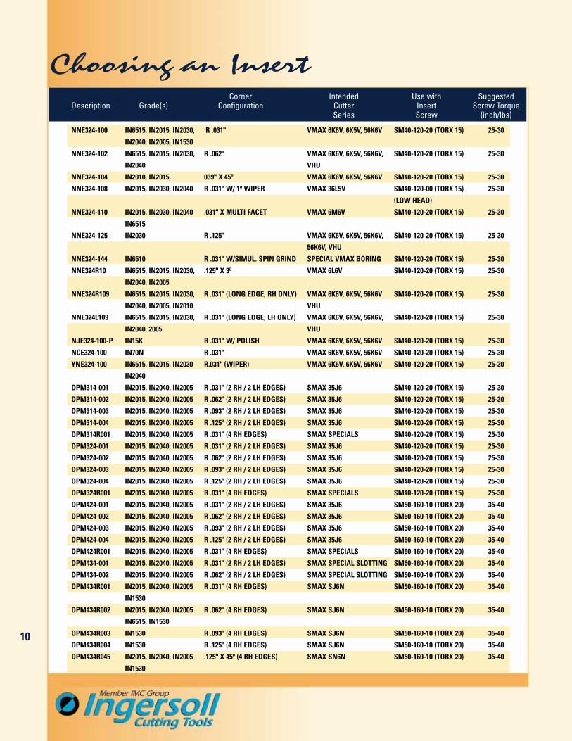
Choosing an InsertCorner Intended Use with Suggested
Description Grade(s) Configuration Cutter Insert Screw TorqueSeries Screw (inch/lbs)
NNE324-100 IN6515, IN2015, IN2030, R .031" VMAX 6K6V, 6K5V, 56K6V SM40-120-20 (TORX 15) 25-30
IN2040, IN2005, IN1530
NNE324-102 IN6515, IN2015, IN2030, R .062" VMAX 6K6V, 6K5V, 56K6V, SM40-120-20 (TORX 15) 25-30
IN2040 VHU
NNE324-104 IN2010, IN2015, 039" X 45º VMAX 6K6V, 6K5V, 56K6V SM40-120-20 (TORX 15) 25-30
NNE324-108 IN2015, IN2030, IN2040 R .031" W/ 1º WIPER VMAX 36L5V SM40-120-00 (TORX 15) 25-30
(LOW HEAD)
NNE324-110 IN2015, IN2030, IN2040 .031" X MULTI FACET VMAX 6M6V SM40-120-20 (TORX 15) 25-30
IN6515
NNE324-125 IN2030 R .125" VMAX 6K6V, 6K5V, 56K6V, SM40-120-20 (TORX 15) 25-30
56K6V, VHU
NNE324-144 IN6510 R .031" W/SIMUL. SPIN GRIND SPECIAL VMAX BORING SM40-120-20 (TORX 15) 25-30
NNE324R10 IN6515, IN2015, IN2030, .125" X 3º VMAX 6L6V SM40-120-20 (TORX 15) 25-30
IN2040, IN2005
NNE324R109 IN6515, IN2015, IN2030, R .031" (LONG EDGE; RH ONLY) VMAX 6K6V, 6K5V, 56K6V SM40-120-20 (TORX 15) 25-30
IN2040, IN2005, IN2010 VHU
NNE324L109 IN6515, IN2015, IN2030, R .031" (LONG EDGE; LH ONLY) VMAX 6K6V, 6K5V, 56K6V, SM40-120-20 (TORX 15) 25-30
IN2040, 2005 VHU
NJE324-100-P IN15K R .031" W/ POLISH VMAX 6K6V, 6K5V, 56K6V SM40-120-20 (TORX 15) 25-30
NCE324-100 IN70N R .031" VMAX 6K6V, 6K5V, 56K6V SM40-120-20 (TORX 15) 25-30
YNE324-100 IN6515, IN2015, IN2030 R.031" (WIPER) VMAX 6K6V, 6K5V, 56K6V SM40-120-20 (TORX 15) 25-30
IN2040
DPM314-001 IN2015, IN2040, IN2005 R .031" (2 RH / 2 LH EDGES) SMAX 35J6 SM40-120-20 (TORX 15) 25-30
DPM314-002 IN2015, IN2040, IN2005 R .062" (2 RH / 2 LH EDGES) SMAX 35J6 SM40-120-20 (TORX 15) 25-30
DPM314-003 IN2015, IN2040, IN2005 R .093" (2 RH / 2 LH EDGES) SMAX 35J6 SM40-120-20 (TORX 15) 25-30
DPM314-004 IN2015, IN2040, IN2005 R .125" (2 RH / 2 LH EDGES) SMAX 35J6 SM40-120-20 (TORX 15) 25-30
DPM314R001 IN2015, IN2040, IN2005 R .031" (4 RH EDGES) SMAX SPECIALS SM40-120-20 (TORX 15) 25-30
DPM324-001 IN2015, IN2040, IN2005 R .031" (2 RH / 2 LH EDGES) SMAX 35J6 SM40-120-20 (TORX 15) 25-30
DPM324-002 IN2015, IN2040, IN2005 R .062" (2 RH / 2 LH EDGES) SMAX 35J6 SM40-120-20 (TORX 15) 25-30
DPM324-003 IN2015, IN2040, IN2005 R .093" (2 RH / 2 LH EDGES) SMAX 35J6 SM40-120-20 (TORX 15) 25-30
DPM324-004 IN2015, IN2040, IN2005 R .125" (2 RH / 2 LH EDGES) SMAX 35J6 SM40-120-20 (TORX 15) 25-30
DPM324R001 IN2015, IN2040, IN2005 R .031" (4 RH EDGES) SMAX SPECIALS SM40-120-20 (TORX 15) 25-30
DPM424-001 IN2015, IN2040, IN2005 R .031" (2 RH / 2 LH EDGES) SMAX 35J6 SM50-160-10 (TORX 20) 35-40
DPM424-002 IN2015, IN2040, IN2005 R .062" (2 RH / 2 LH EDGES) SMAX 35J6 SM50-160-10 (TORX 20) 35-40
DPM424-003 IN2015, IN2040, IN2005 R .093" (2 RH / 2 LH EDGES) SMAX 35J6 SM50-160-10 (TORX 20) 35-40
DPM424-004 IN2015, IN2040, IN2005 R .125" (2 RH / 2 LH EDGES) SMAX 35J6 SM50-160-10 (TORX 20) 35-40
DPM424R001 IN2015, IN2040, IN2005 R .031" (4 RH EDGES) SMAX SPECIALS SM50-160-10 (TORX 20) 35-40
DPM434-001 IN2015, IN2040, IN2005 R .031" (2 RH / 2 LH EDGES) SMAX SPECIAL SLOTTING SM50-160-10 (TORX 20) 35-40
DPM434-002 IN2015, IN2040, IN2005 R .062" (2 RH / 2 LH EDGES) SMAX SPECIAL SLOTTING SM50-160-10 (TORX 20) 35-40
DPM434R001 IN2015, IN2040, IN2005 R .031" (4 RH EDGES) SMAX SJ6N SM50-160-10 (TORX 20) 35-40
IN1530
DPM434R002 IN2015, IN2040, IN2005 R .062" (4 RH EDGES) SMAX SJ6N SM50-160-10 (TORX 20) 35-40
IN6515, IN1530
DPM434R003 IN1530 R .093" (4 RH EDGES) SMAX SJ6N SM50-160-10 (TORX 20) 35-40
DPM434R004 IN1530 R .125" (4 RH EDGES) SMAX SJ6N SM50-160-10 (TORX 20) 35-40
DPM434R045 IN2015, IN2040, IN2005 .125" X 45º (4 RH EDGES) SMAX SN6N SM50-160-10 (TORX 20) 35-40
IN1530

11
INSERTS (0˚ Lead)
HARDWARE
Grades
SM50-160-10 (SE03-70) 35-40 in. lbs. DS-0034
Insert Screw DriverPart No. Torque Part No.
.709
.300.551
Insert Insert CornerColor Code Number IN 1530 2005 2015 2040 6515
DPM434R001 .031R � � � �
DPM434R002 .062R � � � �
DPM434R003 .093R �
DPM434R004 .125R �
DPM434R
D1 New Number D2 InsertEffective Cutter of H Bore Bolt ColorDiameter Number Inserts Height Diameter Circle Keyway Code
3.000 SJ6N-03R01 5 2.375 1.00 - .374.000 SJ6N-04R01 6 2.375 1.50 - .636.000 SJ6N-06R01 10 2.375 1.50 - .638.000 SJ6N-08R01 12 2.375 2.50 4.00 1.0010.000 SJ6N-10R01 14 2.375 2.50 4.00 1.0012.000 SJ6N-12R01 16 2.375 2.50 4.00, 7.00 1.00
0˚ LEAD HEAVY DEPTH FACE MILL SERIES SJ6N
Diameters Cutting Edge Length Insert Corner3.00" to 12.00" .68" (4RH) .031", .062"R

INSERTS (45˚ Lead)
HARDWARE
Grades
SM50-160-10 (SE03-70) 35-40 in. lbs. DS-0034(Tx-20)
Insert Screw DriverPart No. Torque Part No.
.709
.300.551
Insert Insert CornerColor Code Number IN 1530 2005 2015 2040
DPM434R045 .125” X 45˚ � � � �
DPM434R
45˚ LEAD HEAVY FEED FACE MILL SERIES SN6N
Diameters Cutting Edge Length Insert Corner3.00" to 12.00" .350" (4RH) .125" x 45˚
D1 New Number D2 InsertEffective Cutter of H Bore Bolt ColorDiameter Number Inserts Height Diameter Circle Keyway Code
3.000 SN6N-03R01 5 2.375 1.00 - .374.000 SN6N-04R01 6 2.375 1.50 - .636.000 SN6N-06R01 8 2.375 1.50 - .638.000 SN6N-08R01 10 2.375 2.50 4.00 1.0010.000 SN6N-10R01 12 2.375 2.50 4.00 1.0012.000 SN6N-12R01 14 2.375 2.50 4.00, 8.00 1.00
12

Diameters Width of Cut Insert Corner4”, 5”, 6”, 8”, 10" .625" - 1.000" .031", .062”, .093”, .125”R
(2RH/2LH)
W1 D1 New D2 W2 D3 Number of InsertCutter Nominal Cutter Bore Hub Hub Effective ColorWidth Diameter Number Diameter Width Diameter Keyway Inserts Code
.625 4.000 3SJ6E-04062AG-01 1.250 .625 2.25 .32 5
.750 4.000 3SJ6H-04075AG-01 1.250 .750 2.25 .32 51.000 4.000 3SJ6L-04100AG-01 1.250 1.000 2.75 .32 4.625 5.000 3SJ6E-05062AH-01 1.500 .625 2.75 .38 6.750 5.000 3SJ6H-05075AH-01 1.500 .750 2.75 .38 61.000 5.000 3SJ6L-05100AH-01 1.500 1.000 2.75 .38 5.625 6.000 3SJ6E-06062AH-01 1.500 .625 3.50 .38 7.750 6.000 3SJ6H-06075AH-01 1.500 .750 3.50 .38 71.000 6.000 3SJ6L-06100AH-01 1.500 1.000 3.50 .38 6.625 8.000 3SJ6E-08062AK-01 2.000 .625 3.50 0.5 8.750 8.000 3SJ6H-08075AK-01 2.000 .750 3.50 0.5 81.000 8.000 3SJ6L-08100AK-01 2.000 1.000 3.50 0.5 7.625 10.000 3SJ6E-10062AK-01 2.000 .625 3.50 0.5 9.750 10.000 3SJ6H-10075AK-01 2.000 .750 3.50 0.5 91.000 10.000 3SJ6L-10100AK-01 2.000 1.000 3.50 0.5 8
HEAVY-DUTY AXIAL DRIVE SLOTTER SERIES 3SJ6
Axial Driv
e
13

14
Diameters Width of Cut Insert Corner4”, 5”, 6”, 8”, 10" .625" - 1.000" .031", .062”, .093”, .125”R
(2RH/2LH)
W1 D1 New D2 W2 D3 Number of InsertCutter Nominal Cutter Bore Hub Hub K Effective ColorWidth Diameter Number Diameter Width Diameter Keyway Inserts Code
.625 4.000 3SJ6E-0406257-01 1.00 1.50 2.00 .38 5
.750 4.000 3SJ6H-0407557-01 1.00 1.50 2.00 .38 51.000 4.000 3SJ6L-0410057-01 1.00 1.50 2.00 .38 4.625 5.000 3SJ6E-0506257-01 1.00 1.50 2.75 .38 6.750 5.000 3SJ6H-0507557-01 1.00 1.50 2.75 .38 6
1.000 5.000 3SJ6L-0510057-01 1.00 1.50 2.75 .38 5.625 6.000 3SJ6E-0606258-01 1.50 2.00 3.81 .63 7.750 6.000 3SJ6H-0607558-01 1.50 2.00 3.81 .63 7
1.000 6.000 3SJ6L-0610058-01 1.50 2.00 3.81 .63 6.625 8.000 3SJ6E-0806258-01 1.50 2.00 3.81 .63 8.750 8.000 3SJ6H-0807558-01 1.50 2.00 3.81 .63 8
1.000 8.000 3SJ6L-0810058-01 1.50 2.00 3.81 .63 7.625 10.000 3SJ6E-1006261-01 2.50 2.00 4.87 1.00 9.750 10.000 3SJ6H-1007561-01 2.50 2.00 4.87 1.00 9
1.000 10.000 3SJ6L-1010061-01 2.50 2.00 4.87 1.00 8
HEAVY-DUTY RADIAL DRIVE SLOTTER SERIES 3SJ6
Radial Driv
e
14

15
INSERTS (Slotting)
HARDWARE
Grades
SM40-120-20 (SE02-81) (DPM314, DPM324) 25-30 in. lbs. (DPM314, DPM324) DS-T15T (Tx-15)(DPM314, DPM324)
SM50-160-10 (SE03-70) (DPM424) 35-40 in. lbs. (DPM424) DS-0034 (Tx-20)(DPM424)
Insert Screw DriverPart No. Torque Part No.
.413
.250.400
Insert Insert CornerColor Code Number IN 2015 2040 2005
DPM314-001 .031 � � �
DPM314-002 .062 � � �
DPM314-003 .094 � � �
DPM314-004 .125 � � �
DPM324-001 .031 � � �
DPM324-002 .062 � � �
DPM324-003 .094 � � �
DPM324-004 .125 � � �
DPM424-001 .031 � � �
DPM424-002 .062 � � �
DPM424-003 .094 � � �
DPM424-004 .125 � � �
DPM314-
.500
.250.400
DPM324-
.591
.300.551
DPM424-

16
30° FACE MILL SERIES VM6V
Diameters Cutting Edge Length Insert Corner2.50" to 12.00" .180" .032" x 45˚
D1 New Old Number D2 D3Effective Cutter Cutter of H Bore Bolt OverallDiameter Number Number Inserts Height Diameter Circle Diameter
2.500 VM6V-02R25 6M6V-02R25 6 2.375 1.000 - 2.9703.000 VM6V-03R01 6M6V-03R01 8 2.375 1.000 - 3.4704.000 VM6V-04R01 6M6V-04R01 10 2.375 1.500 - 4.4705.000 VM6V-05R01 6M6V-05R01 12 2.375 1.500 - 5.4706.000 VM6V-06R01 6M6V-06R01 14 2.375 1.500 - 6.4708.000 VM6V-08R01 6M6V-08R01 18 2.375 2.500 4.00 8.47010.000 VM6V-10R01 6M6V-10R01 22 2.375 2.500 4.00 10.47012.000 VM6V-12R01 6M6V-12R01 26 2.375 2.500 4.00, 7.00 12.470
INSERTS (30˚)
HARDWARE
Grades
SM40-120-20 (SE02-81) 25-30 in. lbs. DS-T15T(Tx-15)
Insert Screw DriverPart No. Torque Part No.
.500
.250.485
Insert CornerNumber IN 2015 2030 2040 6515
NNE324-110 (2x) .031" x 45˚ � � � �
NNE324
Will also accept NNE324-100, NNE432-102 but surface finish will be affected.
Utilize
8 Corn
ers
(with
RH only)

17
3° FACE MILL SERIES VL6V
Diameters Cutting Edge Length Insert Corner2.50" to 12.00" .200" .031"R
D1 New New Number D2 D3Effective Cutter Cutter of H Bore Bolt OverallDiameter Number Number Inserts Height Diameter Circle Diameter
2.500 VL6V-02R25 6L6V-02R25 6 2.375 1.000 - 2.5893.000 VL6V-03R01 6L6V-03R01 8 2.375 1.000 - 3.0894.000 VL6V-04R01 6L6V-04R01 10 2.375 1.500 - 4.0895.000 VL6V-05R01 6L6V-05R01 12 2.375 1.500 - 5.0896.000 VL6V-06R01 6L6V-06R01 14 2.375 1.500 - 6.0898.000 VL6V-08R01 6L6V-08R01 18 2.375 2.500 4.00 8.08910.000 VL6V-10R01 6L6V-10R01 22 2.375 2.500 4.00 10.08912.000 VL6V-12R01 6L6V-12R01 26 2.375 2.500 4.00, 7.00 12.089
INSERTS (3˚)
HARDWARE
Grades
SM40-120-20 (SE02-81) 25-30 in. lbs. DS-T15T(Tx-15)
Insert Screw DriverPart No. Torque Part No.
.500
.250.485
Insert CornerNumber IN 2005 2015 2030 2040 6515
NNE324R107 .031R � � � � �
NNE324
A comprehensive selection of standard metric tools of this cutter series is available. Contact your sales agent for more information. The metric tools utilize the same inserts.
Utilize
8 Corn
ers
(with
RH only)
Will also accept NNE324-100, NNE432-102 but surface finish will be affected.

18
PLUNGING CUTTER* SERIES VHU
*Can be used with system.
Diameters Cutting Edge Length Insert Corner2.00" to 6.00" .47" .031", .063", .125"R
.23" or less for 90˚ shoulder
D1 New Number D2Nominal Cutter K1 of H Bore RetentionDiameter Number Keyway Inserts Height Diameter Bolt
Right-Hand Rotation2.00 VHU-20015D1R01 .32 4 1.570 .750 SD06-462.50 VHU-25015D1R01 .32 5 1.570 .750 SD06-463.00 VHU-30020D3R01 .38 5 2.000 1.000 SD08-474.00 VHU-4001958R01 .63 7 1.970 1.500 -5.00 VHU-5001958R01 .63 9 1.970 1.500 -6.00 VHU-6001958R01 .63 11 1.970 1.500 -
Left-Hand Rotation2.00 VHU-20015D1L01 .32 4 1.570 .750 SD06-462.50 VHU-25015D1L01 .32 5 1.570 .750 SD06-463.00 VHU-30020D3L01 .38 5 2.000 1.000 SD08-474.00 VHU-4001958L01 .63 7 1.970 1.500 -5.00 VHU-5001958L01 .63 9 1.970 1.500 -6.00 VHU-6001958L01 .63 11 1.970 1.500 -
90˚ Lead
Note: RH plungers can use remaining insert edges from a RH 0˚ lead 6K6V, 6K5V or 4W2A cutter If using long edge V-Max use a RH insert in a LH tool and a LH insert in a RH tool.
INSERTS (Plunge)
HARDWARE
Grades
SM40-120-20 (SE02-81) 25-30 in. lbs. DS-T15T(Tx-15)
Insert Screw DriverPart No. Torque Part No.
.500
.250.485
NNE324
Insert CornerNumber IN 1530 2005 2015 2030 2040 6515
NNE324-100 .031R � � � � � �
NNE324-102 .063R � � � �
NNE324-125 .125R �

19
Diameters Width of Cut Insert Corner4.000" to 8.000" .375" and .500" .031"R
W1 D1 New Old D2 W2 D3 Number ofCutter Nominal Cutter Cutter Bore Hub Hub K EffectiveWidth Diameter Number Number Diameter Width Diameter Keyway Inserts
.375 4.000 3VL5-04037AG-01 36L5V-04037AG-01 1.250 .375 2.25 .32 5
.500 4.000 3VL5-04037AG-01 36L5V-04037AG-01 1.250 .500 2.25 .32 5
.375 5.000 3VL5-05037AH-01 36L5V-05037AH-01 1.500 .375 2.75 .38 6
.500 5.000 3VL5-05050AH-01 36L5V-05050AH-01 1.500 .500 2.75 .38 6
.375 6.000 3VL5-06037AH-02 36L5V-06037AH-02 1.500 .375 2.75 .38 7
.500 6.000 3VL5-06050AH-02 36L5V-06050AH-02 1.500 .500 2.75 .38 7
.375 8.000 3VL5-08037AK-01 36L5V-08037AK-01 2.000 .375 3.50 .50 8
.500 8.000 3VL5-08050AK-01 36L5V-08050AK-01 2.000 .500 3.50 .50 8
Diameters Width of Cut Insert Corner4.000" to 8.000" .375" and .500" .031"R
W1 D1 New Old D2 W2 D3 Number ofCutter Nominal Cutter Cutter Bore Hub Hub K EffectiveWidth Diameter Number Number Diameter Width Diameter Keyway Inserts
.375 4.000 3VL5-04037D3R01 36L5V-04037D3R01 1.000 1.50 2.00 .38 5
.500 4.000 3VL5-04050D3R01 36L5V-04050D3R01 1.000 1.50 2.00 .38 5
.375 5.000 3VL5-05037D3R01 36L5V-05037D3R01 1.000 1.50 2.75 .38 6
.500 5.000 3VL5-05050D3R01 36L5V-05050D3R01 1.000 1.50 2.75 .38 6
.375 6.000 3VL5-0603758R02 36L5V-0603758R02 1.500 2.00 3.80 .63 7
.500 6.000 3VL5-0605058R02 36L5V-0605058R02 1.500 2.00 3.80 .63 7
.375 8.000 3VL5-0803758R01 36L5V-0803758R01 1.500 2.00 3.80 .63 8
.500 8.000 3VL5-0805058R01 36L5V-0805058R01 1.500 2.00 3.80 .63 8
MEDIUM DENSITY FACE MOUNT SLOTTERS SERIES 3VL5
Axial Driv
e
Radial Driv
e

INSERTS (Slotting)
HARDWARE
Grades
SE02-75 25-30 in. lbs. DS-T15T(Tx-15)
Insert Screw DriverPart No. Torque Part No.
.500
.250.485
Insert CornerNumber IN 2015 2030 2040
NNE324-108 .031R � � �
NNE324
NNE324-108 Insert (shown above) utilizes a wiper flat to extendtool life and provide exceptional side wall finish when slotting.
Product-Update
20
SM40-120-00 (SE02-75) 25-30 in. lbs. DS-T15T(Tx-15)

21
0° COARSE-DENSITY FACE MILL SERIES VK6V
D2
D1
H
.23 Max Docfor90˚ Shoulder
.46MaxDoc
D1 New Old Number D2Effective Cutter Cutter of H Bore BoltDiameter Number Number Inserts Height Diameter Circle Keyway
Coarse Density - Right-Hand Rotation2.000 VK6V-02R02 6K6V-02R02 3 1.570 0.750 - .323.000 VK6V-03R02 6K6V-03R02 5 2.375 1.000 - .384.000 VK6V-04R02 6K6V-04R02 6 2.375 1.500 - .636.000 VK6V-06R02 6K6V-06R02 8 2.375 1.500 - .638.000 VK6V-08R02 6K6V-08R02 10 2.375 2.500 4.00 1.0010.000 VK6V-10R02 6K6V-10R02 12 2.375 2.500 4.00, 7.00 1.0012.000 VK6V-12R02 6K6V-12R02 14 2.375 2.500 4.00, 7.00 1.00
Coarse Density - Left-Hand Rotation2.000 VK6V-02L02 6K6V-02L02 3 1.570 0.750 - .323.000 VK6V-03L02 6K6V-03L02 5 2.375 1.000 - .384.000 VK6V-04L02 6K6V-04L02 6 2.375 1.500 - .636.000 VK6V-06L02 6K6V-06L02 8 2.375 1.500 - .638.000 VK6V-08L02 6K6V-08L02 10 2.375 2.500 4.00 1.0010.000 VK6V-10L02 6K6V-10L02 12 2.375 2.500 4.00, 7.00 1.0012.000 VK6V-12L02 6K6V-12L02 14 2.375 2.500 4.00, 7.00 1.00
Diameters Cutting Edge Length Insert Corner2.00" to 12.00" .46" .031", .063", .125"R and
.23" (4RH/4LH) .031” x 45˚ chamfer

0° MEDIUM-DENSITY FACE MILL SERIES VK6V
D2
D1
H
.23 Max Docfor90˚ Shoul
.46MaxDoc
Diameters Cutting Edge Length Insert Corner2.00" to 12.00" .46" .031", .063", .125"R and
.25" (4RH/4LH) .031” x 45˚ chamfer
D1 New Old Number D2Effective Cutter Cutter of H Bore BoltDiameter Number Number Inserts Height Diameter Circle Keyway
Medium Density - Right-Hand Rotation2.000 VK6V-02R01 6K6V-02R01 5 1.570 0.750 - .322.500 VK6V-02R25 6K6V-02R25 6 1.570 1.000 - .383.000 VK6V-03R01 6K6V-03R01 8 2.375 1.000 - .384.000 VK6V-04R01 6K6V-04R01 9 2.375 1.500 - .635.000 VK6V-05R01 6K6V-05R01 10 2.375 1.500 - .636.000 VK6V-06R01 6K6V-06R01 13 2.375 1.500 - .638.000 VK6V-08R01 6K6V-08R01 16 2.375 2.500 4.00 1.0010.000 VK6V-10R01 6K6V-10R01 20 2.375 2.500 4.00, 7.00 1.0012.000 VK6V-12R01 6K6V-12R01 24 2.375 2.500 4.00, 7.00 1.00
Medium Density - Left-Hand Rotation2.000 VK6V-02L01 6K6V-02L01 5 1.570 0.750 - .322.500 VK6V-02L25 6K6V-02L25 6 1.570 1.000 - .383.000 VK6V-03L01 6K6V-03L01 8 2.375 1.000 - .384.000 VK6V-04L01 6K6V-04L01 9 2.375 1.500 - .635.000 VK6V-05L01 6K6V-05L01 10 2.375 1.500 - .636.000 VK6V-06L01 6K6V-06L01 13 2.375 1.500 - .638.000 VK6V-08L01 6K6V-08L01 16 2.375 2.500 4.00 1.0010.000 VK6V-10L01 6K6V-10L01 20 2.375 2.500 4.00, 7.00 1.0012.000 VK6V-12L01 6K6V-12L01 24 2.375 2.500 4.00, 7.00 1.00
A comprehensive selection of standard metric tools of this cutter series is available. Contact your sales agent for more information. The metric tools utilize the same inserts.22

A comprehensive selection of standard metric tools of this cutter series is available. Contact your sales agent for more information. The metric tools utilize the same inserts. 23
0° HI-DENSITY FACE MILL SERIES VK5V
D2
D1
H
.23 Max Docfor90˚ Shoulder
.46MaxDoc
Diameters Cutting Edge Length Insert Corner2.00" to 12.00" .46" .031", .063", .125R and
.23" (4RH/4LH) .031" x 45° chamfer
D1 New Old Number D2Effective Cutter Cutter of H Bore BoltDiameter Number Number Inserts Height Diameter Circle Keyway
High Density - Right-Hand Rotation2.000 VK5V-02R01 6K5V-02R01 6 1.570 0.750 - .322.500 VK5V-02R25 6K5V-02R25 8 1.570 1.000 - .383.000 VK5V-03R01 6K5V-03R01 10 2.375 1.000 - .384.000 VK5V-04R01 6K5V-04R01 13 2.375 1.500 - .635.000 VK5V-05R01 6K5V-05R01 16 2.375 1.500 - .636.000 VK5V-06R01 6K5V-06R01 21 2.375 1.500 - .638.000 VK5V-08R01 6K5V-08R01 26 2.375 2.500 4.00 1.0010.000 VK5V-10R01 6K5V-10R01 32 2.375 2.500 4.00, 7.00 1.0012.000 VK5V-12R01 6K5V-12R01 38 2.375 2.500 4.00, 7.00 1.00
High Density - Left-Hand Rotation2.000 VK5V-02L01 6K5V-02L01 6 1.570 0.750 - .322.500 VK5V-02L25 6K5V-02L25 8 1.570 1.000 - .383.000 VK5V-03L01 6K5V-03L01 10 2.375 1.000 - .384.000 VK5V-04L01 6K5V-04L01 13 2.375 1.500 - .635.000 VK5V-05L01 6K5V-05L01 16 2.375 1.500 - .636.000 VK5V-06L01 6K5V-06L01 21 2.375 1.500 - .638.000 VK5V-08L01 6K5V-08L01 26 2.375 2.500 4.00 1.0010.000 VK5V-10L01 6K5V-10L01 32 2.375 2.500 4.00, 7.00 1.0012.000 VK5V-12L01 6K5V-12L01 38 2.375 2.500 4.00, 7.00 1.00

Diameters Cutting Edge Length Insert Corner3.00" to 10.00" .46" .031", .063", .125R and
.23” (4RH/4LH) .031" x 45° chamfer
0˚ HEAVY-DUTY HALF-SIDE MILL SERIES 5VK6
D2
D3
D1
H
.23 Max Docfor 90˚ Shoulder
.46MaxDoc
A comprehensive selection of standard metric tools of this cutter series is available. Contact your sales agent for more information. The metric tools utilize the same inserts.
24
D1 New Old Number D2 D3Effective Cutter Cutter of H Bore MountingDiameter Number Number Inserts Height Diameter Diameter
Right-Hand Rotation3.000 5V6K-03075AFR01 56K6V-03075AFR01 8 0.750 1.000 2.004.000 5V6K-04075AHR01 56K6V-04075AHR01 9 0.750 1.500 2.755.000 5V6K-05075AHR01 56K6V-05075AHR01 10 0.750 1.500 2.756.000 5V6K-06075AHR01 56K6V-06075AHR01 13 0.750 1.500 2.758.000 5V6K-08075AKR01 56K6V-08075AKR01 16 0.750 2.00 4.0010.000 5V6K-10075AKR01 56K6V-10075AKR01 20 0.750 2.00 4.00
Left-Hand Rotation3.000 5V6K-03075AFL01 56K6V-03075AFL01 8 0.750 1.000 2.004.000 5V6K-04075AHL01 56K6V-04075AHL01 9 0.750 1.500 2.755.000 5V6K-05075AHL01 56K6V-05075AHL01 10 0.750 1.500 2.756.000 5V6K-06075AHL01 56K6V-06075AHL01 13 0.750 1.500 2.758.000 5V6K-08075AKL01 56K6V-08075AKL01 16 0.750 2.00 4.0010.000 5V6K-10075AKL01 56K6V-10075AKL01 20 0.750 2.00 4.00
Product Note: Full and half pitch axial Keyway on stock tools

25
Grades
INSERTS (0˚ Lead)
.500
.250.485
NNE324R/L
.500
.250.485
NNE324/YNE324
.500
.250.485
NJE324
.500
.250.485
NCE324
Insert Application Corner Cut EdgeNumber Configuration IN 2005 2010 2030 2015 2040 1530 6515 15K 70N
NNE324-100 Multi-Purpose .031R 4RH/4LH � � � � � �
NNE324-102 Multi-Purpose .063R 4RH/4LH � � � �
NNE324-104 Multi-Purpose .031 x 45° 4RH/4LH � �
NNE324-125 Multi-Purpose .125R 4RH/4LH �
YNE324-100 Wiper .031R 2RH/2LH � � � �
NNE324R109 Multi-Purpose .031R 4RH � � � � � �
NNE324L109 Multi-Purpose .031R 4LH � � � � � �
NJE324-100-P Aluminum .031R 4RH/4LH (Polished) �
NCE324-100 Iron .031R 4RH/4LH (SiNit) �
26
Grades
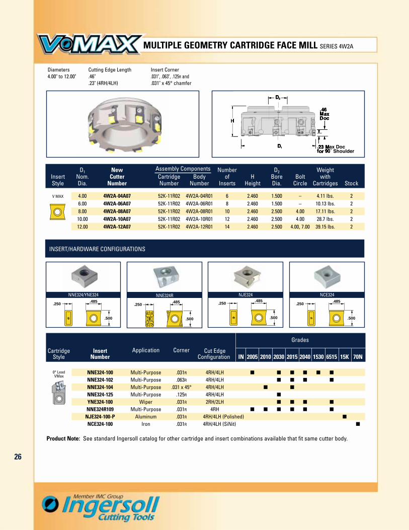
MULTIPLE GEOMETRY CARTRIDGE FACE MILL SERIES 4W2A
INSERT/HARDWARE CONFIGURATIONS
D1 New Assembly Components Number D2 WeightInsert Nom. Cutter Cartridge Body of H Bore Bolt withStyle Dia. Number Number Number Inserts Height Dia. Circle Cartridges Stock
V MAX 4.00 4W2A-04A07 52K-11R02 4W2A-04R01 6 2.460 1.500 – 4.11 lbs. 26.00 4W2A-06A07 52K-11R02 4W2A-06R01 8 2.460 1.500 – 10.13 lbs. 28.00 4W2A-08A07 52K-11R02 4W2A-08R01 10 2.460 2.500 4.00 17.11 lbs. 210.00 4W2A-10A07 52K-11R02 4W2A-10R01 12 2.460 2.500 4.00 28.7 lbs. 212.00 4W2A-12A07 52K-11R02 4W2A-12R01 14 2.460 2.500 4.00, 7.00 39.15 lbs. 2
.500
.250.485
NNE324R
.500
.250.485
NNE324/YNE324
.500
.250.485
NJE324
.500
.250.485
NCE324
0° LeadVMax
Cartridge Insert Application Corner Cut EdgeStyle Number Configuration IN 2005 2010 2030 2015 2040 1530 6515 15K 70N
NNE324-100 Multi-Purpose .031R 4RH/4LH � � � � � �
NNE324-102 Multi-Purpose .063R 4RH/4LH � � � �
NNE324-104 Multi-Purpose .031 x 45° 4RH/4LH � �
NNE324-125 Multi-Purpose .125R 4RH/4LH �
YNE324-100 Wiper .031R 2RH/2LH � � � �
NNE324R109 Multi-Purpose .031R 4RH � � � � � �
NJE324-100-P Aluminum .031R 4RH/4LH (Polished) �
NCE324-100 Iron .031R 4RH/4LH (SiNit) �
Product Note: See standard Ingersoll catalog for other cartridge and insert combinations available that fit same cutter body.
Diameters Cutting Edge Length Insert Corner4.00" to 12.00" .46" .031", .063", .125R and
.23" (4RH/4LH) .031" x 45° chamfer

27
CHIP THINNING (SLOTTING)
OPERATING PARAMETERS
To find the Radial Chip Thinning Factor for a slotting cut:1. Find the Depth of Cut on the horizontal scale. 2. Locate the nominal diameter of the cutter on the vertical axis. 3. Cross-reference the two figures. 4. Locate the diagonal line closest to the intersection of the vertical and horizontal axes.
The value of this diagonal is the Radial Chip Thinning Factor for your specific application.5. Multiply this radial chip thinning factor with the calculated chip thickness to get the actual chip thickness.
2
3
4
56789
10
1214161820
2530
2
3
4
5678910
1214161820
2530
.05 .06 .08 .1 .12
.14 .16 .18 .2 .25 .3 .4 .5 .6 .7 .8 .9 .95 1.0
.01 .02 .03 .04 .05 .06 .08 0.1 .15 0.2 0.3 0.4 0.6 0.8 1 2 3 4 5 6 7 8 10 12 15
.01 .02 .03 .04 .05 .06 .08 0.1 .15 0.2 0.3 0.4 0.6 0.8 1 2 3 4 5 6 7 8 10 12 15
DEPTH OF CUT
DEPTH OF CUT
CU
TT
ER
DIA
ME
TE
R
CU
TT
ER
DIA
ME
TE
R
Chip Thinning • Operating Parameters
Brinell Feed perMaterial Hardness SFM Insert Coolant
Aluminum 6061-T6, 7075-T6, 2024 - 1500-3000 .004-.015 1 Yes
Cast IronGray
150-280400-750
.005-.012 2 1 NoNodular 300-6501500+ .004-.007 1
Low Carbon 1018, 8620 150-250 250-500 .005-.010High Carbon F-6180,
250-400 200-350 .005-.008Steel
Nitralloy 521002 1 3 No
Alloyed Steel150-300
250-400 .005-.0104140, 4340, 6150Tool Steel A-6, D-1, D-2, P-20 Up to 300
Stainless300 Series, 304, 316 - 250-400
Steel 400 Series, 15-5 PH, 17-4 PH Up to 320 300-600.003-.006
1 2 313-8 PH - 200-250 .004-.008 Yes
Nickel Inconel 600, 706, 718,- 75-120 .003-.006 1 3 2 YesAlloys 903, Hastelloy, Waspalloy
Titanium 6AL-4V - 100-150 .003-.006 2 3 1 Yes*In order of preference.
IN15
K (P
olish
ed)
IN70
N
IN20
05
Grades*
IN20
40
IN20
30
IN20
15/IN
2010
IN65
15
IN15
30
May not berequired at
high speeds

28
Operating Parameters
IN20
05
Grades*
IN20
40
IN20
15
Cast Iron
Steel
StainlessSteel
NickelAlloys
Titanium
Gray
Nodular
Low Carbon 1018, 8620
High Carbon F-6180Nitralloy 52100
Alloyed Steel4140, 4340, 6150
Tool Steel A-6, D-1, D-2, P-20
300 Series 304, 316
400 series, 15-5 PH, 17-4 PH
13-8 PH
Inconel 600, 706, 718903, Hastelloy, Waspalloy
6AL-4V
150-280
150-250
250-400
150-300
Up to 300
-
Up to 300
-
-
-
400-750
300-650
250-500
200-350
250-400
250-400
300-600
200-250
75-120
100-150
.005-.012
.005-.010
.005-.008
.005-.010
.003-.006
.004-.008
.003-.006
.003-.006
No
No
May not berequired at
high speeds
Yes
Yes
Yes
1
2
2
2
1
2
2
1
1
1
Material SFM CoolantBrinell
HardnessFeed per
Insert
IN20
05IN
1530
IN65
15
Grades*
IN20
40
IN20
15
Cast Iron
Steel
StainlessSteel
NickelAlloys
Titanium
Gray
Nodular
Low Carbon 1018, 8620
High Carbon F-6180Nitralloy 52100
Alloyed Steel4140, 4340, 6150
Tool Steel A-6, D-1, D-2, P-20
300 Series 304, 316
400 series, 15-5 PH, 17-4 PH
13-8 PH
Inconel 600, 706, 718903, Hastelloy, Waspalloy
6AL-4V
150-280
150-250
250-400
150-300
Up to 300
-
Up to 300
-
-
-
400-750
300-650
250-500
200-350
250-400
250-400
300-600
200-250
75-120
100-150
.007-.018
.005-.015
.006-.013
.006-.015
.005-.010
.006-.012
.004-.007
.004-.007
No
No
May not berequired at
high speeds
Yes
Yes
Yes
1 2
1
3
2
2
2
1
3
1
1
2
Material SFM CoolantBrinell
HardnessFeed per
Insert
INSERT SERIES: DPM314/DPM324
INSERT SERIES: DPM424/DPM434

Grade and Carbide Selection
Grade Material
IN2015 / IN2010 Grey, ductile, nodular iron dry or wet, low to medium cutting speed, low to medium chip thickness.
IN6515 Grey, ductile, nodular iron dry, medium to high cutting speed, medium to highchip thickness. Heavily interrupted cuts.
IN1530 General purpose mild steel, hi-temp alloys, or stainless steel. Interrupted cuts. Wet.
IN2030 / IN2005 Hi-temp alloys. Poor set-up rigidity. Wet or dry.
IN2040 General purpose mild steel and steel alloys, ductile and nodular iron (dry only), when set-up rigidity is good.
IN6542 / IN6510 Grey, ductile, nodular iron dry or wet, non-interrupted milling, low to medium cutting speed, medium to high chip thickness.
IN15K (w/polish) Non-ferrous materials. Wet.
IN70N Grey, ductile, nodular iron dry only, very high speed, low to medium chip thickness.
NewCL
Material
Directionof
Use
Wear ResistanceToughness
Increase FeedIncrease Speed
C1 C2 C3 C4
K50 K45 K40 K35 K30 K25 K20 K15 K10 K05 K01
Short Chipping Malleable Iron, Non-Ferrous Metal,Hardened Iron, Chilled Iron, Cast Iron
Free Cutting Steels, Malleable Iron, Steel Casting, Steel
C5 C6 C7 C8
P50 P45 P40 P35 P30 P25 P20 P15 P10 P05 P01
Wear ResistanceToughness
Increase FeedIncrease SpeedHigh-Temp Alloys, Alloy
Iron, Steel Casting,Manganese
M50 M40 M30 M20 M10
Wear ResistanceToughness
Increase FeedIncrease Speed
Coating
IN15KIN6510IN6515IN1530IN2005IN2010IN2015IN2030IN2040N70N
UncoatedCVDCVDPVDPVDPVDPVDPVDPVD
Non-Carbide
IN6510
IN6515 IN6515
IN2005 IN2005
IN2030 IN2030
IN2040
IN70N
IN1530
IN2010
IN2015 IN2015 IN2015
IN2030
IN1530 IN1530
IN15K
29
CHOOSING A GRADE
CARBIDE SELECTION GUIDE

Standard Inserts for Special Steel
30
.413
.250.400
DPM314R
.500
.250.400
DPM324R
.591
.300.551
DPM424R
Grades
Insert Insert CornerColor Code Number IN 2015 2040 2005 1530
DPM434-001 .031 � � � �
DPM434-002 .062 � � �
.709
.300.551
DPM434-
Grades
Insert Insert CornerColor Code Number IN 2015 2040 2005
DPM314R001 .031 � � �
DPM324R001 .031 � � �
DPM424R001 .031 � � �
INSERTS: 0˚ LEAD RH ONLY
INSERTS: SLOTTING RH/LH

General Application Information
31
The following information is directedtoward indexable carbide tools but itcan be applied to many other cuttingtools, as well. It provides some basicguidelines designed to serve as astarting point for safe and reliable per-formance. Contact your IngersollCutting Tool Company sales engineeror distributor for specific applicationassistance.
Rigidity. Use the most rigid cutter pos-sible. This usually means the cutterwith the largest diameter and shortestlength. Use the best adaption possible.Integral tapers, such as a 50 V-flange,are better than straight shanks. Whenselecting straight shank tools, use acutter with the largest diameter shankpossible and a holder with the shortestlength possible.
Effective cutting edges. When calcu-lating feed rate, use the effective num-ber of inserts. In extended flute cut-ters, the effective number of inserts isnot the number of rows. Use the effec-tive number listed with the specifica-tions for each series of tools.
Chip load. Carbide cutting tools haveto take a “bite” to cut. Be sure to cutwith an adequate chip load. Light chiploads can contribute to chatter, caus-ing a cutter to “rub” instead of “bite.”This can also result in poor tool life. Asa general rule, chip loads should notbe less than .004". Also, be sure to useRadial Chip Thinning Factors (RCTF)when calculating feed rates.
Chip recutting. Unlike HSS, carbidecutting tools cannot recut chips.Recutting chips will damage carbide.To evacuate chips, use air or coolantdepending on the material being cut.
Coolant. Generous amounts of coolantare required when low thermal con-ductivity, work hardening, and chipwelding tendencies are evident.
Use coolant only when necessary.Some materials cut better dry. In someapplications, coolant causes thermalcracking of inserts and poor tool life.
Feed rates. Reduce feed rates by 50percent when entering or exiting a cut.Since fewer inserts are engaged in thework, pounding can occur. Reducingfeed rates will reduce the shock of theinterrupted cut and contribute tolonger tool life.
When entering a corner during pocketmilling, a larger portion of the cutter’sdiameter is engaged. Power require-ments and tool deflection increase. Tocompensate, program a reduced inter-polated feed rate. Alternately, drill orplunge the corner prior to milling.
Cutter rotation. Climb cut wheneverpossible. Carbide is designed for climbmilling and will not generally performas well when conventional cutting.
Conventional cutting may be employedon older machines to minimize back-lash. It can also extend tool life insandy, scaly, or torch-cut surfaces asthe cutting edge enters into cleaner,softer material.
Feed
Feed
Feed
APPLYING BASIC PRINCIPLES OF MACHINING WITH INDEXABLES CAN IMPROVE PERFORMANCE
Reduce feed rates by 50% when entering a cut, exiting a cut, or entering a corner. This reduces pounding and cutting forcesand can extend the life of your indexable carbide tool.
Entering a Cut Exiting a Cut Corner Cutting

32
Standard Milling Formulas
Revolutions per Minute
3.82 x SFMDiameter
RPM =
Horsepower
WOC x DOC x IPMK
HP =
Feed per Insert
FPRNo. Eff. Insert
FPI =
Inches per Minute
IPM = RPM x FPR
Feed per Revolution
IPMRPM
FPR =
Material
AluminumBrass-SoftBrass-HardBronze-HardBronze-VHCast Iron 200 BhnCast Iron > 200 BhnSteel 100 BhnSteel 150 BhnSteel 200 BhnSteel 250 BhnSteel 400 BhnStainless SteelHigh Temp Alloys
"K" Factors
3.0 - 4.03.02.01.4
.5 - .71.5 - 2.01,3 - 1.8
1.5.9.7.6.5
.5 - 1.0.3 - .8
Horsepower equals MaterialRemoval Rate divided by the"K" Factor
Surface Speed per Minute
SFM = .26 x Diameter x RPM

33
MODIFIED STANDARDS AND SPECIALS
PRODUCT WORKSHEETS- APPENDIX -

APPLICATION DATA
REMARKS
WORKPIECE MATERIAL
AVG. RADIAL DOC
RPM
FEED RATE
MACHINE TYPE
MACHINE H.P.
MAX. TOOL ASSY. WEIGHT
appendix • product worksheet
VARIABLE FEATURES
THIS PAGE MAY BE COPIED AND VARIABLES FILLED IN TO COMMUNICATE BASIC DESIGN REQUIREMENTS
MEASUREMENT UNITS USED
INCH MM
SLOTTING/SLABBINGAND T-SLOTTINGA:________________________
B:________________________
C:________________________
D:________________________
E:________________________
F:________________________
G:________________________
H:________________________
suggested diameter 4.00”+
34

235
APPLICATION DATA
REMARKS
WORKPIECE MATERIAL
AVG. RADIAL DOC
RPM
FEED RATE
MACHINE TYPE
MACHINE H.P.
MAX. TOOL ASSY. WEIGHT
appendix • product worksheet
VARIABLE FEATURES
THIS PAGE MAY BE COPIED AND VARIABLES FILLED IN TO COMMUNICATE BASIC DESIGN REQUIREMENTS
MEASUREMENT UNITS USED
INCH MM
HEAVY-DUTY SHELL MILL
Coolant thru: yes no
A:________________________
B:________________________
C:________________________
D:________________________
E:________________________
F:________________________
G:________________________
suggested diameter 2.00”+

2
APPLICATION DATA
REMARKS
WORKPIECE MATERIAL
AVG. RADIAL DOC
RPM
FEED RATE
MACHINE TYPE
MACHINE H.P.
MAX. TOOL ASSY. WEIGHT
appendix • product worksheet
VARIABLE FEATURES
THIS PAGE MAY BE COPIED AND VARIABLES FILLED IN TO COMMUNICATE BASIC DESIGN REQUIREMENTS
MEASUREMENT UNITS USED
INCH MM
HEAVY-DUTYENDMILLING
Coolant thru: yes no
Adaption style:____________________________
A:________________________
B:________________________
C:________________________
D:________________________
E:________________________
suggested diameter 1.50”+
36

37
APPLICATION DATA
VARIABLE FEATURES
REMARKS
WORKPIECE MATERIAL
AVG. AXIAL DOC
RPM
FEED RATE
MACHINE TYPE
MACHINE H.P.
MAX. TOOL ASSY. WEIGHT
THIS PAGE MAY BE COPIED AND VARIABLES FILLED IN TO COMMUNICATE BASIC DESIGN REQUIREMENTS
MEASUREMENT UNITS USED
INCH MM
appendix • product worksheet
STRADDLE MILLINGFULL SIDE MILLING
Cutter #1 quantity of inserts:___________
Cutter # 2 quantity of inserts:__________
Adaption style:____________________________
A:________________________
B:________________________
C:________________________
D:________________________
E:________________________
F:________________________
G:________________________
H:________________________
I:_________________________
J:________________________
OptionalPA-0613 Anvil

38
APPLICATION DATA
VARIABLE FEATURES
REMARKS
WORKPIECE MATERIAL
AVG. AXIAL DOC
RPM
FEED RATE
MACHINE TYPE
MACHINE H.P.
MAX. TOOL ASSY. WEIGHT
THIS PAGE MAY BE COPIED AND VARIABLES FILLED IN TO COMMUNICATE BASIC DESIGN REQUIREMENTS
MEASUREMENT UNITS USED
INCH MM
appendix • product worksheet
COMBINATION FINISH FACE MILLProposed quantity of rougher inserts:________________________
Proposed quantity of finisher inserts:_________________________
Rougher l-nest protection/adjustment requested: . . . . . . yes no
Coolant manifold requested: . .yes no
A:________________________
B:________________________
C:________________________
D:________________________
E:________________________
F:________________________

39
APPLICATION DATA
REMARKS
WORKPIECE MATERIAL
AVG. RADIAL DOC
RPM
FEED RATE
MACHINE TYPE
MACHINE H.P.
MAX. TOOL ASSY. WEIGHT
appendix • product worksheet
VARIABLE FEATURES
THIS PAGE MAY BE COPIED AND VARIABLES FILLED IN TO COMMUNICATE BASIC DESIGN REQUIREMENTS
MEASUREMENT UNITS USED
INCH MM
quantity of inserts:_______________________
Adaption style:____________________________
Coolant thru: . . . . . . . . . . . . yes no
L-nest pocket protection/adjustment requested . . . . . . .yes no
BORING
A:________________________
B:________________________
C:________________________
D:________________________
E:________________________
suggested diameter 2.50”+
optional PAR0615/PAL0615
nest

Ingersoll Cutting Tools for the Americas Ingersoll Cutting Tools for Europe
Marketing & Technology Center Marketing & Technology Center845 S. Lyford Road Ingersoll Werkzeuge GmbHRockford, IL 61108-2749 U.S.A. Kalteiche-Ring 21-25
35708 Haiger, GermanyTel: 815.387.6600Fax: 815.387.6968 Tel: 02773.742 0Email: [email protected] Fax: 02773.742 812/814Internet: www.ingersoll-imc.com Email: [email protected]
Internet: www.ingersoll-imc.deIngersoll Cutting Tool Ltd.4510 Rhodes Drive, Unit #100Windsor, Ontario N8W 5K5, Canada
Tel: 519.974.1019Fax: 519.974.2260
Ingersoll Cutting Tools de México S.A. de C.V.Carr. Saltillo Monterrey Km. 5.5, Local 2 y 3Saltillo, Coahuila C.P. 25200, México
Tel: (844) 432.2546, (844) 432.2547Fax: (844) 432.2544
CAT-008-1 (1-05)