
Outstanding ASME TURBO EXPO ‘01files.asme.org/IGTI/News/25216.pdfGAS TURBINE NEWS IN BRIEF...
20
IN THIS ISSUE... TURBO EXPO ‘01 1, 10-12 Value Added Knowledge 2 News in Brief 3 Compressor Fouling 4-9 Certification 13 Distributed Power Generation in Europe 15 In Memorium... Jack Chauvin 17 Outstanding ASME TURBO EXPO ‘01 Shaping Up for New Orleans by Dilip Ballal, IGTI Chair of Conferences J oin the more than 4500 gas turbine and power industry professionals from over 60 countries around the world who will gather in New Orleans, Louisiana 4-7 June 2001 for the premier event of the interna- tional gas turbine community: ASME TURBO EXPO—Land, Sea & Air (TE’01). The theme “New Horizons in Global Power” will be prevalent throughout this dynamic four-day event covering everything about gas turbines. Highlights include: distributed power generation, micro tur- bines, fuel cells, design concepts, technical innovations, maintenance, repair, retrofitting, certification, after-market issues and much more. Keynote Highlights A joint TE’01 / IJPGC* Keynote Session will feature one of the most impressive groups of speakers ever assembled for an IGTI event! The Keynote theme will be, “New Horizons in Global Power … Manufacturer- User Dialogue.” To address this theme, we are proud to have the partici- pation of the following outstanding Keynote speakers: ❖ Del Williamson, President, GE Power Systems Global Sales ❖ Randy Zwirn, President & CEO, Siemens Westinghouse Power Corporation ❖ Larry Izzo, President & CEO, Enron Engineering and Construction Company ❖ Wayne MacIntire, Senior Manager Power Technology, International Paper, Inc. These distinguished speakers will present the views of buyers and s- ellers in the power generation arena. Rita A. Bajura, Director of the National Energy Technology Laboratory of the DOE, will summarize the Keynoters’ comments and relate future DOE activity to “New Horizons in Global Power.” Audience questions will be taken by the Keynoters. Over 1,000 delegates are expected to attend this opening Keynote Session. Technical Congress Highlights Nearly 600 refereed papers assembled into 124 technical sessions and 22 panels, tutorials and discussion sessions will combine to provide the information you need for problem solving and career advancement. The program for New Orleans includes vital gas turbine issues, such as: CIRCULATION 20,000 • ATLANTA, GEORGIA USA • ASME INTERNATIONAL GAS TURBINE INSTITUTE Volume 40: 2000, No. 3 ...continued on page 10 Rita A. Bajura DEL WILLIAMSON RANDY ZWIRN LARRY IZZO WAYNE MacINTIRE
Transcript of Outstanding ASME TURBO EXPO ‘01files.asme.org/IGTI/News/25216.pdfGAS TURBINE NEWS IN BRIEF...

IN THISISSUE...
TURBO EXPO ‘01
1, 10-12
Value AddedKnowledge
2
News in Brief
3
Compressor Fouling
4-9
Certification
13
Distributed PowerGeneration in Europe
15
In Memorium...Jack Chauvin
17
Outstanding ASME TURBO EXPO ‘01Shaping Up for New Orleansby Dilip Ballal, IGTI Chair of Conferences
Join the more than 4500 gas turbine and power industry professionalsfrom over 60 countries around the world who will gather in NewOrleans, Louisiana 4-7 June 2001 for the premier event of the interna-
tional gas turbine community: ASME TURBO EXPO—Land, Sea & Air(TE’01). The theme “New Horizons in Global Power” will be prevalentthroughout this dynamic four-day event covering everything about gasturbines. Highlights include: distributed power generation, micro tur-bines, fuel cells, design concepts, technical innovations, maintenance,repair, retrofitting, certification, after-market issues and much more.
Keynote HighlightsA joint TE’01 / IJPGC* Keynote Session will feature one of the most
impressive groups of speakers ever assembled for an IGTI event! TheKeynote theme will be, “New Horizons in Global Power … Manufacturer-User Dialogue.” To address this theme, we are proud to have the partici-pation of the following outstanding Keynote speakers:
❖ Del Williamson, President, GE Power Systems Global Sales ❖ Randy Zwirn, President & CEO, Siemens Westinghouse
Power Corporation ❖ Larry Izzo, President & CEO, Enron Engineering and
Construction Company ❖ Wayne MacIntire, Senior Manager Power Technology,
International Paper, Inc.
These distinguished speakers will present the views of buyers and s-ellers in the power generation arena. Rita A. Bajura, Director of theNational Energy Technology Laboratory of the DOE, will summarize theKeynoters’ comments and relate future DOE activity to “New Horizons inGlobal Power.” Audience questions will be taken by the Keynoters. Over1,000 delegates are expected to attend this opening Keynote Session.
Technical Congress HighlightsNearly 600 refereed papers assembled into 124 technical sessions and
22 panels, tutorials and discussion sessions will combine to provide theinformation you need for problem solving and career advancement. Theprogram for New Orleans includes vital gas turbine issues, such as:
CIRCULATION 20,000 • ATLANTA, GEORGIA USA • ASME INTERNATIONAL GAS TURBINE INSTITUTE
Volume 40: 2000, No. 3
...continued on page 10Rita A. Bajura
DEL WILLIAMSON
RANDY ZWIRN
LARRY IZZO
WAYNE MacINTIRE

2 Global Gas Turbine News Volume 40: 2000, No.3
VIEW FROM THE CHAIRBOB KIELB, CHAIR, IGTI BOARD OF DIRECTORS
ences. This will range from detailed descriptionsof IGTI’s Gas Turbine Users Symposium, Exposi-tion, and Technical Congress to online registra-tion. The job of putting the events together willbe made more efficient through the use of elec-tronic forms and reports available on an asneeded basis through the “Community” pages.
Detailed descriptions of additional gas tur-bine resources can be found under “Services.”These include not only ASME and IGTI offerings,but also other significant gas turbine publica-tions and information sources. Descriptions ofIGTI’s popular Home Study Courses and itsscholarship program will also be included.
The “Community” pages are designed forthose who want to know more about, or becomeinvolved in, IGTI activities. Included is contactinformation about IGTI leaders and staff, detailson committee structure and areas of responsibil-ity, web-based program guides and forms, andaccess to the Gas Turbine Forum.
IGTI products previously ordered through theIGTI Atlanta office and all new products will nowalso be available for online purchase.
IGTI’s revised and greatly expanded web site<http://www.asme.org/igti/> is scheduled forlaunch in early December 2000. Our vision is tomake it your portal for any and all gas turbineinformation. We ask for your comments on theabove, and for your ideas to help make IGTI theforemost provider of value added knowledge tothe gas turbine community. Please mail yourcomments to me at <[email protected]>.
Keep your turbines turning! ✲
Establish IGTI as the foremost provider ofvalue added knowledge to the gas turbinecommunity.” This is one of the primary
goals in IGTI’s strategic plan. Although there islittle argument that the TURBO EXPO Congress isthe pre-eminent conference for the latest gasturbine technology, serving the knowledgerequirements of the gas turbine communityrequires many more year-round services and activ-ities. In addition to TURBO EXPO, IGTI currentlyoffers a newsletter, scholarships, home studycourses, and the annual Gas Turbine TechnologyReport & Product Directory. The IGTI Board ofDirectors, however, believes we need to do more.
We see the IGTI web site as a primary vehiclefor providing the gas turbine community witheasy access to increased gas turbine knowledge.As a result, the IGTI staff is completely revamp-ing our web site. The web site under constructionconsists of five primary areas: Resources, Events,Services, Community, and IGTI Store.
Debuting as a principal gas turbine resource is“SourceGT,” an electronic industry reference forthe exchange of gas turbine educational andtechnical information. SourceGT follows in thefootsteps of IGTI’s annual Technology Report &Product Directory which served as a leading gasturbine global report for over a dozen years. As aweb-based resource, SourceGT listings can beadded and updated continuously and thus offerthe newest and best data to site visitors. Listingsand web links of leading companies will beavailable by product and service category.
The “Events” area of the web site contains allof the necessary information on IGTI confer-
Bob KielbChair
IGTI Board of Directors
We see the IGTI web site as a primary vehicle forproviding the gas turbine community with easy access
to increased gas turbine knowledge.
❝
❞
Value Added Knowledge
“

GAS TURBINE NEWSIN BRIEF
WILLIAMS INTERNATIONAL’Sfirst FJ33 engine in its new family of 1200 to1500-pound thrust turbofans successfully com-pleted its first test run on July 26. The enginedemonstrated favorable margin to fuel con-sumption goals, displayed very low vibration,and very low oil consumption, besides exceed-ing thrust targets. The FJ33 is being developedto power a new class of light jets in the 5000-to-9000-pound gross-takeoff-weight class.
CATALYTICA COMBUSTIONSYSTEMS, INC., a subsidiary of Cata-lytica, Inc., has been awarded $1.6 millionunder a U.S. Department of Energy spon-sored program to help fund research anddevelopment of durable and cost-effective low emissions tech-nologies for small gas tur-bines used in distributedpower generation. Theproject will focus oncatalyst life exten-sion, cost reduction,and application ofCatalytica’s XononCool CombustionTM
technology.
S&S ENERGY PRODUCTS has an-nounced a new addition to its LM product line, the
18-megawatt GE LM2000 aeroderivative gas turbine-generator set. A derating of GE’s popular LM2500, the
LM2000 will offer 18 megawatts for power generation,24,000 shaft horsepower for mechanical drive uses, and a
35.5% thermal efficiency. The engine will have a lower firing tem-perature with hot section replacement intervals expected to be extended to
approximately twice those of the LM2500.
PRATT & WHITNEY CANADA CORP.(P&WC) marked an important milestone in its 72-year
history on November 16 with the delivery of its50,000th engine. The engine, a PT6A-67D, wasdelivered to RAYTHEON AIRCRAFT.Raytheon (Beech) Aircraft became the first cus-tomer for P&WC’s legendary PT6 turboprop enginein 1963 when it selected the engine to power thenow famous Beech King Air. Pratt Canada currentlyproduces an average 2,000 engines a year.
SIEMENS WESTINGHOUSE POWER CORPORATIONand CHROMALLOY GAS TURBINE CORPORATION, asubsidiary of Sequa Corporation, are forming a joint venture to support the growthof the Siemens gas turbine fleet. Siemens owns 51 percent of Turbine Airfoil Coat-ing & Repair LLC (TACR), which will provide for the repair of Siemens industrial
gas turbine blades and vanes, the coating of repaired components, andthe coating of new blades and vanes.
Volume 40: 2000, No.3 Global Gas Turbine News 3
CAPSTONE TURBINE CORPORATION has announced alicensing agreement with SOLAR TURBINES INCORPORATEDto manufacture recuperators, an integral part of the Capstone MicroTurbine sys-tem. The companies have worked together for three years to develop advancedautomated manufacturing techniques for the Solar-designed product.
PRATT & WHITNEY’S newest engine, the PW6000, took to the air forthe first time August 21, successfully completing a one hour and 20 minuteflight. The 16,000- to 24,000-pound thrust PW6000 is the launch engine for thenew Airbus Industrie A318 100-passenger airplane. The A318/PW6000 combina-tion will complete its certification and enter service in late 2002.
Gas Turbine News in Brief ... is compiled for Global Gas Turbine News by Carl E. Opdyke, Power Systems Aerospace Analyst, FORECAST INTERNATIONAL,
22 Commerce Road, Newtown, Connecticut 06470
PRATT & WHITNEY SMALL MILITARY ENGINES (SME)and TELEDYNE CONTINENTAL MOTORS (TCM) have signed a Memorandum of Agreement to pursue teaming in areas of development, manufac-turing, and technical and product support of small military engines products andservices. This product line would include Uninhabited Air Vehicle (UAV) enginesup to 16,000 pounds of thrust for U.S. Government customers. ✲
The team ofHONEYWELLand GENERAL ELECTRIC have won the Army’s $3+ billion Abrams-Crusader Common Engine (ACCE)program, winning out over competitorsCaterpillar and the team of GeneralDynamics and MTU. Under the program,the Honeywell-GE (HGE) team willreplace the Honeywell AGT 1500 vehiculargas turbine in the Army’s M1 Abrams mainbattle tank and the Caterpillar PerkinsCondor CV12 diesel engine intended forthe Army’s XM2001 Crusader 155 mm self-propelled howitzer. Upwards of 2,800 M1tanks, and about 825 howitzers and resup-ply vehicles are to be covered by the ACCEprogram. The HGE team will redevelop theLV100 design for the ACCE program underthe Army’s $195.6 million contractawarded on September 20.
4 Global Gas Turbine News Volume 40: 2000, No.3
The fouling of axial flow compressors is aserious operating problem in gas turbinesand its control is of supreme importance to
gas turbine operators especially in the currentderegulated and highly competitive power market.Foulants, even in the parts per million (ppm)range, can cause deposits on the blading, resultingin a severe performance deterioration (decre-ment). The effect of compressor fouling is a dropin airflow and compressor efficiency, which resultsin a drop in power output and thermal efficiency.In some extreme cases, fouling can also result insurge problems. This article discusses the mecha-nism of fouling, the effects, types of foulants,detection methods and control techniques. A briefdiscussion on turbine fouling is also presented.
INTRODUCTIONGas turbines ingest large quantities of air. The
solids or condensing particles in the air and inthe combustion gasses can precipitate on therotating and stationary blading causing changesin their aerodynamic profile, dropping the com-pressor air mass flow rate and affecting efficiency.
TECHNOLOGY
COMPRESSOR FOULING ... CAUSES AND SOLUTIONSby Cyrus B. Meher-Homji, P.E., ASME FellowChief Engineer, Gas Turbine Division of Mee Industries, Inc.
Some of the gremlins ofcompressor fouling at work.
❝
❞
A 75 MW unitlocated in an
industrialenvironment
with airloading of
10 ppm willingest 594 lbs.of particulates
in a day.
This has an adverse effect on the unit’s perfor-mance. The output of a gas turbine can drop by asmuch as 10%. Moreover, contaminated air cancause a host of problems that include erosion,fouling, corrosion and, in some cases, plugging ofthe hot section cooling passages.
Some estimates have placed fouling as beingresponsible for 70 to 85 % of all gas turbine per-formance loss accumulated during operation. Sys-tem output losses range between 2% (under favor-able conditions) and 15 to 20 % (under adverseconditions). In a gas turbine about 50 to 60 % ofthe total work produced in the turbine section isutilized by the compressor; therefore, maintaininghigh compressor efficiency is an important con-tributing factor to the plant’s revenue stream.
CAUSES OF FOULINGExperience has shown that axial compressors
will foul in most operating environments, bethey industrial, rural or marine. There are a widerange of industrial pollutants and a range ofenvironmental conditions (fog, rain, humidity)that play a part in the fouling process.
Volume 40: 2000, No.3 Global Gas Turbine News 5
Compressor fouling is typically caused by:
• Airborne salt.• Industrial Pollution - fly ash, hydrocarbons, smog, etc. This causes a grimy
coating on the early stages and can get “baked on” in the latter stages(especially in high pressure ratio compressors).
• Ingestion of gas turbine exhaust or lube oil tank vapors.• Mineral deposits.• Airborne materials - soil, dust, sand, chemical fertilizers, insecticides,
insects and plant matter.• Internal gas turbine oil leaks - axial compressor front bearing is a common
cause. Oil leaks combined with dirt ingestion cause heavy fouling problems.• Impure water from evaporative coolers.• Coal dust and spray paint that is ingested.
The fouling rate for a compressor will be a strong function of the envi-ronment, the climatic conditions, the wind direction and the filtration sys-tem. A 75 MW unit located in an industrial environment with air loading of10 ppm will ingest 594 lbs. of particulates in a day.
Ambient air can be contaminated by solids, liquids and gases. Air load-ings can be defined in mg/m3, grains/1000 ft3 or ppm (mass of contaminantper unit mass of air). In general, particles up to 10 microns cause fouling,but not erosion. Particles above 10 to 20 microns cause blading erosion.Some typical air loadings are: country 0.01 - 0.1 ppm by weight; coastal 0.01 - 0.1 ppm by weight; industrial 0.1 - 10 ppm by weight; and desert 0.1 - 700 ppm by weight.
As air passes through the intake and filtration system, it proceeds at avery low velocity. As it approaches the compressor face, the air accelerates toa high velocity (0.5 - 0.8 Mach number). This results in a static temperaturereduction of about 10-15 C. The saturation air temperature also drops. If thestatic air temperature falls below the saturation air temperature, condensa-tion of water vapor occurs. This is a common occurrence in most gas tur-bines when the relative humidity is even above 50%. Also, the filters tend tounload salt (leeching effect) under high humidity conditions and this is anassociated factor that is often neglected. Particles then form nuclei for thewater droplets and start to adhere to the blading. As the air progresses to therear compressor stages, it gets hotter and drier, typically causing less foulingin the latter stages.
Marine and Offshore EnvironmentThe offshore environment is particularly
challenging. Airborne salt can exist in three basicforms: aerosol, spray, and crystal. Aerosols canrange in size from 2 microns to 20 microns (1 micron = 10-6m or 1/1000 mm). Aerosols aregenerated by bubbles shattering on the sea surface.Sea spray generates large droplets (sized 150 to200 microns) and these tend to drop out due togravity. Sea salt crystals absorb moisture underappropriate relative humidity conditions. The sizeof these peak in the range of 2 microns. The rela-tive humidity off-shore was found to be almostalways high enough to ensure that salt was in itswet form. Studies by Tatge, et al concluded that saltwould stay as supersaturated droplets unless therelative humidity dropped below 45%.
The environment on off-shore platforms isnot “dust free” and can include flare carbon andmud burning foulants (which can be a problemwith poorly positioned flare stacks and with sud-den changes in wind direction), and drillingcement and other dusts (which can be blownaround a rig). Grit blasting has also been aserious problem.
EFFECTS OF FOULINGFouling of axial flow compressors can affect the
aerothermodynamics of the gas turbine, promotecompressor surge, and affect blading integrity.
Aerothermodynamic EffectsThe axial flow compressor is a sensitive com-
ponent that requires smooth aerodynamic sur-faces. Fouling causes an alteration in the shape ofthe blading which reduces airflow rate, pressureratio and compressor efficiency. The overall effectis a drop in thermal efficiency (increase in heatrate) and a drop in output.
An axial compressor is a machine where theaerodynamic performance of each stage dependson the earlier stages. Thus, when fouling occursin the inlet guide vanes and the first few stages,there may be a dramatic drop in compressor per-formance. This can often occur when oil andindustrial smog or pollen are present and forman adhesive wetting agent. The early stages areoften the worst fouled stages. If the rear stagesfoul, this seems to have a smaller impact on per-formance; but due to higher temperatures,deposits can get baked on and become difficultto clean. This baking effect is more severe on thehigh pressure ratio (18 to 30:1) aeroderivative
...continued
TECHNOLOGYCOMPRESSOR FOULING...continued
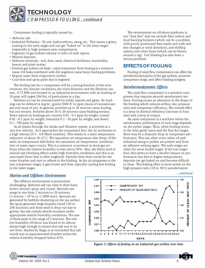
Figure 1: Effects of fouling on an industrial gas turbine over time.

6 Global Gas Turbine News Volume 40: 2000, No.3
machines than on the heavy duty industrial gasturbines (with typical compressor ratios of 10 or 14:1).
Figure 1 (on page 5) shows a fouling processthat occurs in a large gas turbine engine. Thisgraph illustrates the changes in compressor effi-ciency and heat rate over time. The higher theheat rate the lower the overall gas turbine effi-ciency.
Compressor SurgeAs fouling drops the airflow in the first stage,
this affects the performance of the latter stages. Thefirst stage pressure ratio is thus increased. Thiscauses a higher density at the inlet to the secondstage. Thus there will be a further reduction in sec-ond stage flow coefficient. This effect progressesthrough successive stages until a later stage stallstriggering a surge. (See Dundas sidebar to the left.)
The importance of considering fouling effectson surge as a problem becomes more importantwith the use of gas turbines in combined cycle orcogeneration applications utilizing inlet guidevane (IGV) control and steam injection.
There have been several cases where excessivedistortion of the inlet airflow has triggered asurge event resulting in compressor damage.Icing, causing uneven inlet circumferential dis-tortion, or uneven clogging of filters, possiblydue to a bend in the inlet duct before the filter orimproper inlet system design, can create distor-tion effects which could result in surge.
Blading Integrity EffectsWhile fouling cannot be said to be a major
cause of blading failure, it can contribute to blad-ing problems:a) … by promoting surge or rotating stall whichmight have a dangerous effect on blades.
In some unusual cases, blading natural fre-quencies can be affected by the increase in massdue to dirt buildup on the blading causingmechanical distress.b) … by excessive dirt on the blading causingimbalance and a consequent increase in runningspeed vibration. In some cases dirt can getbetween the bearing surfaces of the blade root,causing the blades to operate in a non-normalposition, which would add to the stresses. If theroot constraint is changed due to buildup in thefir tree region, a change in natural frequency couldresult (as the boundary condition changes). c) … by blocking or partial blocking of coolingpassages of hot section stators and blades. Ascooling air is bled from the compressor, foulantssuch as cement dust, coal dust and fly ash canenter the cooling system. The effects can beimproper cooling and accelerated thermal fatigue,
TECHNOLOGYCOMPRESSOR FOULING...continued
though typically the effects are gradual in nature.d) … by leading to a serious corrosion problem,especially with poor filtration and high humid-ity. Corrosion will occur if salt water or salt parti-cles (1-3 microns in size) are ingested into thecompressor. The dry salt or brine will absorbmoisture during high humidity operation or dur-ing water washing. Corrosion is caused by thechemical reaction between the engine compo-nents and airborne contaminants. Salts, mineralacids and aggressive gases (e.g. chlorine) alongwith water can cause wet corrosion and compres-sor blade pitting. This can lead to local stressraisers which can diminish blade fatigue life. Animportant corrosion process in compressors isknown as electrochemical or “wet corrosion”.e) … by causing erosion. Particle sizes of 5-10microns represent the transition zone between foul-ing and erosion. (Note: 10 microns = 1/15 diameterof human hair.) Erosion impairs aerodynamicperformance and can affect the blade mechanicalstrength. Erosion first increases blading surfaceroughness thus lowering efficiency slightly. Aserosion progresses, airfoil contour changes occurat the leading and trailing edge as well at theblade tip. Severe erosion has also been known tocause changes in blade natural frequency.f) … by indirectly contributing to Foreign ObjectDamage (FOD). Though not linked to foulingdirectly, this is mentioned because it could becaused by a loss in filter integrity. Damage is typi-cally to the early compressor stages, though insome cases the foreign object works its way tolater stages also and causes damage. Damage is afunction of size, foreign object composition, bladeconstruction and impact location. It can lead todirect or secondary failure. Foreign object damagecan be caused by ice, failed intake section compo-nents, materials and tools left in the inlet plenum.
DETECTION OFFOULING
Gas turbine manu-facturers and operatorstypically develop guide-lines as to when foulingdeterioration calls forcorrective action. This isusually based on a combina-tion of load and exhaust gastemperatures (EGT). Users alsomonitor compressor dischargepressure and compressor efficiency.Graphs can be plotted to show expected (clean) vsmeasured parameters.
It is the opinion of some operators that theonly way to detect a fouled compressor is by
Dundas [1986]has conducted anexcellent analyticalinvestigation intothe deterioration ofturbine operationincluding drop incompressor effi-ciency, fouling, 1ststage nozzle distor-tion, internal bleedseal deterioration,drop in turbine effi-ciency, inlet filterfouling and low fuelheating value. Thesewere examined tostudy the effect onthe turbine operat-ing line. His studyconcluded thatcompressor foulinghad a pronouncedeffect on the operat-ing line.
While theseeffects cause themovement of theoperating linetoward the surgeline, there are otherfactors that cancause movement ofthe surge line itself.Erosion of compres-sor blading caneffect boundarylayer developmentand increase thetendency towardseparation. Stall cantherefore occur atlower incidencesthan with smoothcompressor blad-ing. Heavy erosioncan also reduceblade tip chords,thereby reducingblade tip solidity,which wouldadversely effectstage stability.
Volume 40: 2000, No.3 Global Gas Turbine News 7
visual inspection. With most turbine designs, however, thismeans shutting the unit down, removing the inlet plenum hatchand visually inspecting the compressor inlet, bellmouth, inletguide vanes (IGVs) and visible early stage blading.
The following factors can be used as indicators of fouling: a)Drop in compressor air (mass) flow rate on fixed geometryengines, and b) Drop in compressor efficiency and pressureratio. The most sensitive of these parameters is the airflow rate.
The real problem is to detect fouling at an appropriate timebefore a significant power drop has occurred and a fuel penaltycost has been paid. Several philosophies are in use. Some opera-tors believe in periodic washing of the machine while othersbase washes on condition (i.e. some set of performance parame-ters). The philosophy utilized is a function of normally expectedfouling level, its severity, washing effectiveness and plant opera-tion criteria. Measurement of air-intake depression is a practicaland economical method for fixed geometry machines. The tech-nique involves measuring intake depression as an analog of air-flow rate. In this approach, the gas turbine inlet bellmouth is uti-lized as a flowmeter.
CONTROL OF FOULING
Fouling is best controlled by a combination of two meth-ods. The first line of defense is to employ a high quality air fil-tration system. If fouling occurs (and it usuallywill) then the compressor can be washed.
FiltrationFilters can be categorized as fol-
lows:Inertial Filters: The objective here
is to make the air change directionrapidly causing separation of dust par-ticles. These filters are permanentlyfixed and require minimal mainte-nance. Inertial filters typically oper-ate at face velocities of 20 ft/second.
Prefilters: These are medium effi-ciency filters made of cotton fabricor spun fiberglass. They are relativelyinexpensive and serve as “protection”for high efficiency filters.
Coalescers: These are constructed by theuse of wire mesh which acts as an agglomer-ater. The mist in the inlet air is agglomeratedand the moisture is thus removed.
Louvers and Vanes: These are typically used in the firststages along with coalescer filters to remove water droplets.
High Efficiency Filters: These filters remove smaller parti-cles of dirt. They are typically barrier or bag type filters.
Self-Cleaning Filters: These consist of a bank of high effi-ciency media filters. Air is drawn through the media at a lowvelocity. At a predetermined pressure drop (about 2-3” WaterGauge) a reverse blast of air is used to remove dust buildup.
TECHNOLOGYCOMPRESSOR FOULING...continued
Air tightness is a must for any gas turbine inlet systembecause even the most efficient filtration system will be useless ifunfiltered airflow enters the compressor. Some common causesof leakage are: bypass door leakage; poor gaskets and seals atflanged points; and modifications made on the inlet ducting. Inthis latter case, over the years personnel may add structures ordevices to the inlet system which might cause problems.
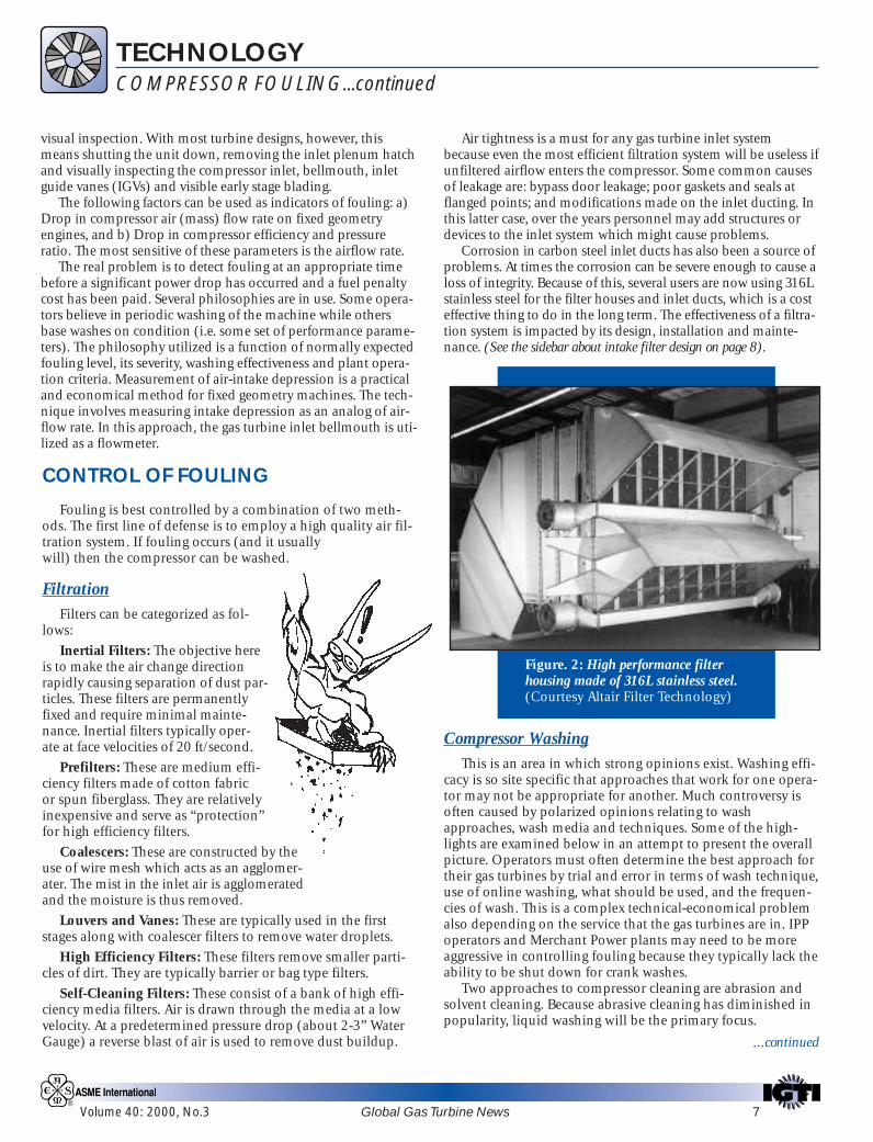
Corrosion in carbon steel inlet ducts has also been a source ofproblems. At times the corrosion can be severe enough to cause aloss of integrity. Because of this, several users are now using 316Lstainless steel for the filter houses and inlet ducts, which is a costeffective thing to do in the long term. The effectiveness of a filtra-tion system is impacted by its design, installation and mainte-nance. (See the sidebar about intake filter design on page 8).
Compressor WashingThis is an area in which strong opinions exist. Washing effi-
cacy is so site specific that approaches that work for one opera-tor may not be appropriate for another. Much controversy isoften caused by polarized opinions relating to washapproaches, wash media and techniques. Some of the high-lights are examined below in an attempt to present the overallpicture. Operators must often determine the best approach fortheir gas turbines by trial and error in terms of wash technique,use of online washing, what should be used, and the frequen-cies of wash. This is a complex technical-economical problemalso depending on the service that the gas turbines are in. IPPoperators and Merchant Power plants may need to be moreaggressive in controlling fouling because they typically lack theability to be shut down for crank washes.
Two approaches to compressor cleaning are abrasion andsolvent cleaning. Because abrasive cleaning has diminished in popularity, liquid washing will be the primary focus.
...continued
Figure. 2: High performance filterhousing made of 316L stainless steel.(Courtesy Altair Filter Technology)

8 Global Gas Turbine News Volume 40: 2000, No.3
TECHNOLOGYCOMPRESSOR FOULING...continued
Water washing (with or without detergents) cleansby water impact and by removing the water solublesalts. It is most important that the manufacturer’s rec-ommendations be followed with respect to waterwash quality, detergent/water ratio and other operat-ing procedures. Typically, wheel space temperaturesmust be below 200 F to avoid thermal shock and thewater wash is done with the machine on crank. Waterwashing using a water-soap mixture is an efficientmethod of cleaning. This cleaning is most effectivewhen carried out in several steps which involve theapplication of a soap and water solution, followed byseveral rinse cycles. Each rinse cycle involves theacceleration of the machine to approximately 50 per-cent of the starting speed, after which the machine isallowed to coast to a stop. A soaking period followsduring which the soapy water solution may work ondissolving the salt.
A fraction of airborne salt always passes throughthe filter. The method recommended for determiningwhether or not the foulants have a substantial saltbase is to soap wash the turbine and collect the waterfrom all drainage ports available. Dissolved salts inthe water can then be analyzed.
Certain filters, during periods of high humidity,were found to “dump” contaminants into the machine,causing a drop in power. There is alsoevidence of phenomena where com-pressors can “clean” themselves.
Online washing is now verypopular as a means to controlfouling by keeping the problemfrom developing. Techniquesand wash systems have nowevolved to a point wherethis can be done effec-tively and safely.Washing can beaccomplished byusing water basedsolvents, petroleumbased solvents, orsurfactants. The solventswork by dissolving thecontaminants while surfactantswork by chemically reacting with thefoulants. Water based solvents are effective against salt,but fare poorly against oily deposits. Petroleum basedsolvents do not effectively remove salty deposits. Withsolvents, there is a chance of foulants being rede-posited in the latter compressor stages.
Even with good filtration, salt can collect in thecompressor section. During the collection process ofboth salt and other foulants, an equilibrium condi-
Some important considerationsin intake filter design are...✶ Aerodynamic design should be such as to
keep intake velocities uniform across theentire filter area.
✶ Filter housing should be of a bolted andwelded design fabricated of steel no lessthan 3/16” thick and reinforced by steelmembers. Filter house should withstand12” water gauge pressure. All seams andjoints should be air tight. All nuts andbolts used inside the clean air plenumshould be welded after assembly toprevent air leaks and foreign objectdamage to the turbine.
✶ Design should facilitate change-out of all filters from theupstream side. Filter change should be possible without tur-bine shutdown. Filter elements should be designed for quickchange-out and the avoidance of blind assembly, loose retain-ing nuts, ungasketed washers, etc.
✶Filter design should ensure that the inlet air is drawn at least 10feet above grade level. (In some locations a greater height maybe required.)
✶ A stainless steel trash screen with 1” square mesh should beprovided in the transition section between the clean airplenum and the compressor intake.
✶ Avoid the use of gravity weighted by-pass doors. Bypass doorsare designed to permit emergency airflow to the engine whenintake pressure drop rises above a critical value. Bypass doorsare typically gravity operated or power operated. The gravitytype has earned a reputation for unreliability. Poor sealing,hinge corrosion and improper operation have made thebypass door a weak link in inlet filter design. Many users havedone away with by-pass doors.
✶ All filter seal points should be reviewed during the designphase. Poor intake sealing has allowed leaks through bypassdoors, access doors and flanges on the intake filter. Severaltimes flange distortion has allowed air ingress. Users shouldspecify types of seals required and call for a filter houseintegrity test under specified depression to ensure airtightness.
✶ System design in the case of pulsed cleaning systems, shouldbe such as to minimize flow distortions and pressure pulsa-tions due to pulse cleaning. More than 5% of the total filterelements should not be cleaned simultaneously.
✶ Filter system pressure drop is an important parameter affectinggas turbine performance. The following rough rules of thumbmay be applied: For aero-derivative gas turbines, every 4” of inletloss will result in a 0.7% increase in heat rate and a 1.6% reduc-tion in power. For heavy duty industrial machines, a 4” inlet losswill result in a 0.6% increase in heat rate and a 1.6% drop inoutput power. It is important to consider both new filter pressuredrop and the pressure drop increase over time.
Volume 40: 2000, No.3 Global Gas Turbine News 9
TECHNOLOGYCOMPRESSOR FOULING...continued
tion is quickly reached, after which reingestion of large particles occurs. Thisreingestion has to be prevented by the removal of salt from the compressorprior to saturation. The rate at which saturation occurs is highly dependenton filter quality. In general, salts can safely pass through the turbine whengas and metal temperatures are less than 1000 F. Aggressive attacks will occurif the temperatures are much higher. During cleaning, the actual instanta-neous rates of salt passage are very high together with greatly increased parti-cle size. (See sidebar at right).
TURBINE SECTION FOULINGWhile turbine section fouling is not typically a serious problem with nat-
ural gas fired gas turbines, contaminants that cause turbine fouling canenter the gas turbine through the inlet air, or through the fuel (if liquid),fuel additives or NOx control injection fluid.
In the hot turbine section, and in the presence of hot gases, low meltingpoint ashes, metals and unburned hydrocarbons can be deposited in theform of scale. As hot combustion products pass through the first stage noz-zle, they experience a drop in static temperature and some ashes may bedeposited on the nozzle blades. Because the throat area of the nozzle con-trols the compressor-turbine matching, a reduction in throat area causes amovement away from the design match point. This then causes a loss in per-formance. Deposits will also form on the rotating blades causing a furtherloss in performance.
Blade and disc cooling can also be impaired by foulants causing a reduc-tion in component life or even failure. Because the fuel flow rate is typicallyabout 2% of the air mass flow rate, 1ppm Na entering from the fuel wouldhave the same effect as just 20 parts per billion (ppb) airborne salt enteringthe airflow. This is a significant requirement considering that most manufac-turers call for not more than .5 ppm of Na. Turbine section fouling is accen-tuated when heavy fuels are used and inhibitors (used to counteract thepresence of Vanadium) cause ash buildup.
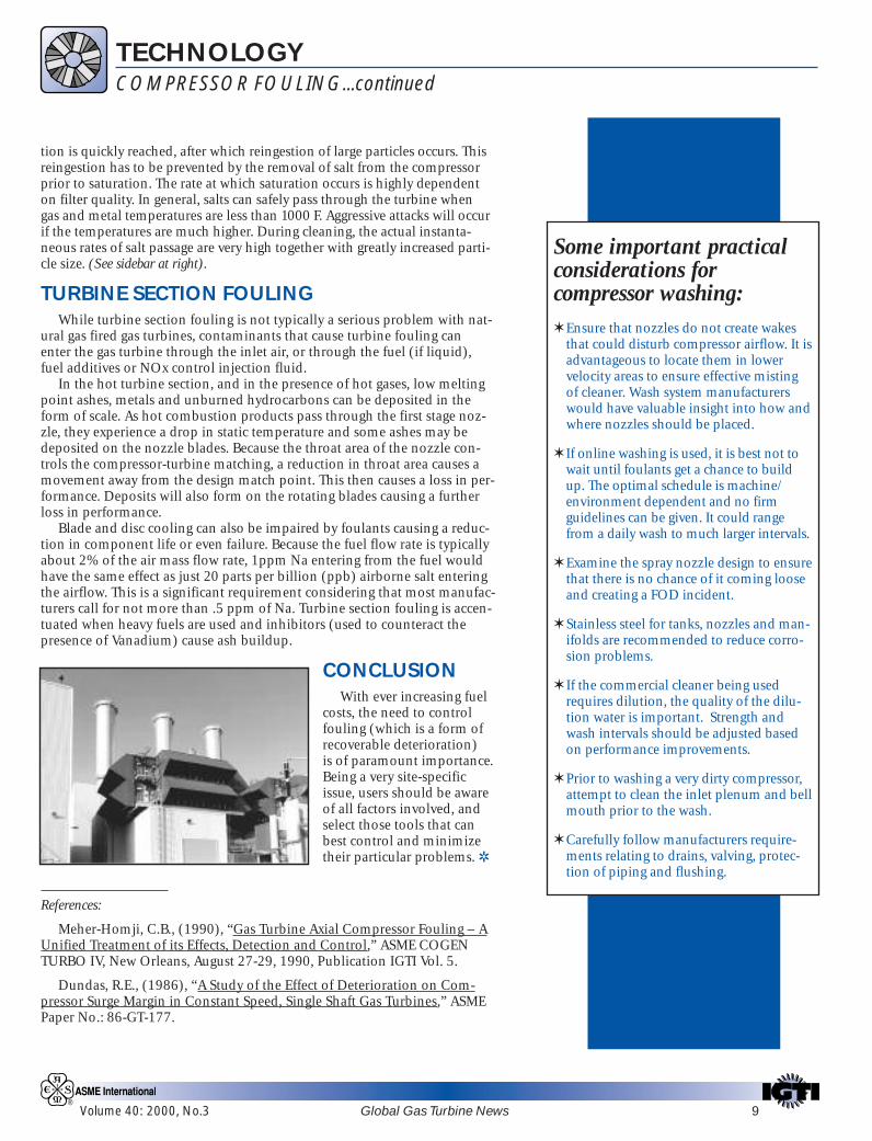
CONCLUSIONWith ever increasing fuel
costs, the need to controlfouling (which is a form ofrecoverable deterioration) is of paramount importance.Being a very site-specificissue, users should be awareof all factors involved, andselect those tools that canbest control and minimizetheir particular problems. ✲
References:
Meher-Homji, C.B., (1990), “Gas Turbine Axial Compressor Fouling – AUnified Treatment of its Effects, Detection and Control,” ASME COGENTURBO IV, New Orleans, August 27-29, 1990, Publication IGTI Vol. 5.
Dundas, R.E., (1986), “A Study of the Effect of Deterioration on Com-pressor Surge Margin in Constant Speed, Single Shaft Gas Turbines,” ASMEPaper No.: 86-GT-177.
Some important practicalconsiderations forcompressor washing:✶ Ensure that nozzles do not create wakes
that could disturb compressor airflow. It isadvantageous to locate them in lowervelocity areas to ensure effective mistingof cleaner. Wash system manufacturerswould have valuable insight into how andwhere nozzles should be placed.
✶ If online washing is used, it is best not towait until foulants get a chance to buildup. The optimal schedule is machine/environment dependent and no firmguidelines can be given. It could rangefrom a daily wash to much larger intervals.
✶ Examine the spray nozzle design to ensurethat there is no chance of it coming looseand creating a FOD incident.
✶ Stainless steel for tanks, nozzles and man-ifolds are recommended to reduce corro-sion problems.
✶ If the commercial cleaner being usedrequires dilution, the quality of the dilu-tion water is important. Strength andwash intervals should be adjusted basedon performance improvements.
✶ Prior to washing a very dirty compressor,attempt to clean the inlet plenum and bellmouth prior to the wash.
✶ Carefully follow manufacturers require-ments relating to drains, valving, protec-tion of piping and flushing.

10 Global Gas Turbine News Volume 40: 2000, No.3
• Next generation intelligent engine controls• Condition monitoring of combined cycle power plants• Advanced gas turbines and novel cycles• Ceramic components durability and life predictions• Control of combustion instabilities• Fuel cells and emissions regulatory issues• Protective coating technology, fatigue, fracture, and life pre-
diction• Unsteady flows in turbomachinery• and much more.
NOTABLE FEATURES: The Technical Congress will include agroup of sessions developed by the IGTI Task Force on Distrib-uted Power, and an exceptional panel on 21st Century AircraftGas Turbine Maintenance & Repair. Each feature is discussedmore fully elsewhere in this newsletter.
Gas Turbine Users Symposium(GTUS) Highlights
To organize the Gas Turbine Users Symposium (GTUS) forTE’01, IGTI has marshaled 20 hand-picked advisors represent-ing power utilities, IPPs, gas transmission, oil and gas produc-tion, and petrochemical industries from four continents todevelop a high-impact forum to benefit gas turbine operatingenterprises throughout the world. The GTUS’s 24 panel, tutor-ial and discussion sessions are presented in three programtracks: “Performance Enhancement and Preservation” … “HotSection Repair and Integrity” … and … “Business and Eco-nomic Strategies.” Session highlights include:• Monitoring, Diagnosis, and Performance Testing• Hot Section Failure Diagnosis; Materials and
Coatings Selection• Maintenance Strategies to Improve Reliability
and Minimize Life Cycle Costs• Emissions Control and Operating Experiences• Fouling, Filtration, Washing, and Fogging• Cogeneration and Combined Cycles• Surge Control for Centrifugal Compressors• and much more.
MORE GTUS HOT TOPICES: Long-term service agreements;conversions, modifications and upgrades; reliability measuresin today’s market; safety; risk management and insurance;networking among GTUS participants, and useful interactionswith OEMs.
Stay up-to-date on TE’01 program developments by loggingonto the IGTI web site at www.asme.org/igti/te2001. Revisit itoften. Even better, at the site click on “Subscribe to E-Bulletin” toget automatic email notification of new postings, including theanticipated January availability of online registration and hous-ing information. TE’01 in New Orleans will be another outstand-ing IGTI event, and we want to make it your best one ever! ✲
KeynoteSession atTURBOEXPO 2000in Munich,Germany.
Part of theExpositionat TURBOEXPO 2000in Munichlast May.
Winner ofPalm VII atThursday’sdrawing inMunich.
* For 2001, ASME TURBO EXPO—Land, Sea & Air and the InternationalJoint Power Generation Conference will co-locate their events. Plans call fora joint Keynote Session, a joint three-day Exposition (4-6 June), and separatetechnical congress registrations (with attendance cross-over privileges).
“TURBO EXPO ‘01”...continued from front page

Volume 40: 2000, No.3 Global Gas Turbine News 11
Three $1,000 Beginning Engineer Fellowships Available
IGTI will provide three travel awards of $1,000 each forbeginning engineers who are presenting papers approved bythe IGTI Review Chair for publication at ASME TURBO
EXPO 2001.To be eligible for an award, a candidate must send an appli-
cation letter to:
Beginning Engineer Fellowship Programc/o Kathy Hawken
International Gas Turbine Institute5775-B Glenridge Dr., Suite 370
Atlanta, GA 30328-5380 USA
The application letter should state that each of the follow-ing items is relevant:
❖ The applicant must be the author or a co-author — andmust be the presenter — of a paper that has been acceptedfor presentation at ASME TURBO EXPO 2001. Applicantshould enclose a copy of the paper abstract.
❖ The applicant must be beginning his/her gas turbine engi-neering career. The criterion for this can be a point of discus-sion in the letter.
❖ The applicant must clearly state that organizational funds toattend the Congress are not available.
Any other pertinent information that the applicant cares toinclude (briefly stated) will be considered. Brevity is encour-aged and the letter should not exceed two pages. The awardcommittee consists of members of the IGTI Board of Directors.
The application letter and abstract should be mailed toarrive at the Atlanta office no later than March 1, 2001. Theaward winners will be notified as soon as possible after thatdate. The checks for $1,000 will be presented on-site at ASMETURBO EXPO 2001 in New Orleans, Louisiana. ✲
$ $ $ $ $ $ $ $ $
New Focus on Distributed Power,Micro Turbines at TE’01 and Beyond
IGTI Task Force on Distributed PowerNorman Holcombe, ChairU.S. Department of Energy
National Energy Technology Laboratory
Industry ...Tim Callahan, Southwest Research InstituteSanjay Correa, General ElectricMary Gerstner, Honeywell Power SystemsAnthony Leo, FuelCell Energy Inc.Ron Natole, Natole Turbine Enterprises Inc.Stephen Veyo, Siemens Westinghouse Power GenerationLeslie Witherspoon, Solar Turbines Inc.
Academia ...Scott Samuelsen, Nat’l. Fuel Cell Research Center
University of California at IrvineRiti Singh, Cranfield University, U. K.
Government ...Debbie Haught, Department of EnergyGeorge Richards, Department of Energy
Users ...Jeffrey Hinson, Director, Utility Services
Clemson UniversityBrian Mueller, Sodexho Marriott ServicesFred Robson, KraftWork Services Inc.
Forecast Internationalpredicts that within thisdecade, deregulation of
power will create unprecedenteddemand for a small-power class(less than 1 MW) of micro turbinesand fuel cells, both separate andcombined. Today, it is possible toproduce power close to its point ofuse, and this distributed powergeneration concept will radicallytransform the electricity business.Under the leadership of Dr. Nor-man Holcombe of the NationalEnergy Technology Laboratory,U.S. Department of Energy, IGTIhas established an ad hoc Task Force on Distributed Power tobring together for discussions and debate all aspects of this hottopic: micro turbines, hybrid engine cycles, fuel cells, control sys-tems, alternate fuels and emissions, equipment design and devel-opment, and user experience.
The 15 members of the task force are drawn from industry,academia, government, and the user community. Technicalpapers, panel discussions, tutorials, and exhibits covering numer-ous aspects of this distributed power revolution will form animportant part of TE ’01. In addition, top-level DOE personnelwill participate in the Technical Congress and GTUS. Thus, the“Big Easy” will be the place to learn the latest about the newest!
Norm Holcombe

Distinguished Panel to Discuss Aircraft Gas Turbine Maintenance & Repair
12 Global Gas Turbine News Volume 40: 2000, No.3
PANELISTS–21ST CENTURY AIRCRAFTGAS TURBINE MAINTENANCE & REPAIR
Otha Davenport, SES, Session ChairDirector of Engineering, Propulsion Product Group
United States Air ForceWright-Patterson Air Force Base, Ohio.
Jason ChamberlainDirector, Pratt and Whitney Engineering
East Hartford, CT
Scott CrislipGeneral Manager, General Electric
Evendale, OH
Ron CherryDirector of Engine Maintenance, Delta Airlines
Atlanta, GA
Jim UhlGeneral Manager, Power Plant Engineering, United Airlines
San Francisco, CA
Dave Pauling, SESHead of Propulsion and Power Engineering, U.S. Navy (NAVAIR)
Patuxent River, MD
The person with engineering responsibility forall U.S. Air Force engines in development,acquisition and operation will chair a world-
class panel at TE’01 to discuss and debate currentengine maintenance practices, continuing improve-ments, and the expected advanced technology enhance-ments for future engines. Otha Davenport, Senior Exec-utive Service, Director of Engineering for the UnitedStates Air Force (USAF) Propulsion Product Group,Wright-Patterson Air Force Base, Ohio will fill this role.
The panel of world technology leaders will includegas turbine manufacturers, commercial airline users,and military users. This “manufacturer-user” dialoguewill parallel the New Orleans Keynote Session, butfocus on aircraft gas turbine maintenance, overhaul,repair, and reliability of both commercial and mili-tary jet engines operating on many aircraft platforms.Affordability, a key ingredient for competitive mainte-nance, will be discussed with the objective of mini-mizing the engine operational flight hour cost.Trending, diagnostics, and prognostics also will bepresented along with discussions centered on main-taining aging engine systems. No one interested in air-craft engines can afford to miss this panel discussion!
TE’01 and IJPGC Welcome Participating Organizations
Three important gas turbine and power generation user organizations, and a Pacific Rim engineering society,will participate with TE’01 and IJPGC in their world-renowned conferences this June. ASME TURBO EXPO—Land, Sea & Air and the International Joint Power Generation Conference, co-locating in New Orleans 4-7
June 2001, are pleased to welcome the following participating organizations:
• World Energy Council (WEC) • ASME Gas Turbine Technical Chapter, Houston• Gulf Coast Power Association (GCPA) • Japan Society of Mechanical Engineers (JSME)
Each of these organizations will be promoting this exciting co-located event to its members and most will behaving a booth in the three-day Exposition. The World Energy Council is represented by its Committee on Perfor-mance of Generating Plant. The committee will be organizing a panel session and also having its own meetingwhile in New Orleans. Its booth in the Exposition will have information available on the WEC meeting next year inBuenos Aires. The Gulf Coast Power Association’s booth will serve as a rendezvous point for its members and haveinformation available for those wishing to join. The members of the very successful ASME Gas Turbine TechnicalChapter in Houston will be available in their booth to offer information and advice to those who may wish to starta Gas Turbine Technical Chapter. JSME will be contributing papers to the IJPGC technical program.
While at TURBO EXPO, take time to visit with these folks and say hello. ✲
Volume 40: 2000, No.3 Global Gas Turbine News 13
Gas Turbine Certification ... An Updateby Lee S. Langston
During 1999 and 2000, in various forumssponsored by IGTI, gas turbine users havecomplained about the performance of
some of the newer, larger (greater than 50 MW)electric power gas turbines, as they enter service.Reports by gas turbine users, buyers, insurers andfinanciers concern problems with some newmachines … problems that range from ones theindustry solved decades ago (rotor vibrations,and inadequate through-bolt assembly proce-dures) to others which might have been solvedbefore going to market (some recent hummingcombination instabilities, and combustion partsthat fail during operation to cause damage todownstream gas path turbine parts). Much totheir dismay, users have concluded that extendedcommissioning periods, performance shortfallsand outages for component repair or replacementhave become all too common with the newestmodels of some large gas turbines.
Last May, two sessions at TURBO EXPO ’00 inMunich were held to address these issues throughthe use of some sort of certification process. Aworldwide certification process has long beenestablished for civil aviation gas turbines. In theUnited States, the third party civil aviation certi-fier is the Federal Aviation Administration (FAA),and in Europe it is the Joint Aviation Administra-tion (JAA). Both of these agencies require proofby test for gas turbine certification.
One Munich certification session, “OpenForum on Standardization and ConformityAssessment Needs for Gas Turbines”, was chairedby Donald Frikken, ASME Vice President of theCouncil on Codes and Standards. The other,“Future Gas Turbine Certification for Land andMarine Applications”, was a panel session orga-nized by Michael Osborne, and Robin Parry, Chairand Vice Chair of IGTI’s Marine Committee.
A number of proposals came out of these twoMunich sessions. A summary report on the ses-sions has been posted by Codes and Standardsstaff member Steve Weinman on the ASME website http://www.asme.org/cns/departments/Stan-dardization/Public/TuboExpo.html.
❝
❞
User power in the marketplace is needed to push forproof by test certification of electric power gas turbines.
Proposals from the two sessions include thefollowing:
❖ More specific specifications are needed todetermine what gas turbine testing is requiredfor certification. These specifications shouldalso include criteria that make it clear when anew gas turbine model is ready for perfor-mance testing.
❖ Along with criteria for comparative testing ofnew gas turbines, guidelines are needed todetermine individuals qualified to carry outthe testing.
❖ To protect a potential gas turbine buyer or user,criteria are needed to define the stage of devel-opment of a new gas turbine model or design.
❖ There is a need for the certification ofcombined cycle power plant operators.
❖ There is a need for the certification of gasturbine maintenance organizations.
The proposals resulting from the two MunichTE’00 sessions have been referred to ASME Codesand Standards committees, PTC 22 and B133,both of which deal with gas turbine issues. It willbe the job of these committees to incorporate theMunich proposals into existing codes and proce-dures wherever that is possible and where itmakes sense to do so.
As a result of these two sessions it is my opin-ion that to go further in a land based gas turbinecertification process—such as rigorous proof bytest required in the civil aviation FAA/JAA pro-gram—users themselves will have to form somesort of coalition. User power in the marketplaceis needed to push for proof by test certificationof electric power gas turbines. ASME Codes andStandards can serve as a focus for standardiza-tion efforts, but a rigorous certification of proofby test can most likely come about through theactions of knowledgeable volunteers who have acommon interest—and control of the gas turbinemarketplace—to make it happen. ✲
Lee S. Langston

A Great Gift for the Holidays–
The History of AircraftGas Turbine EngineDevelopment in theUnited States ...A Tradition of Excellenceby James St. Peter
This absorbing, anecdotal history of gas turbine enginedevelopment spans over 50 years of scientific discovery,corporate intrigue, and insight into the minds of the historic personalities who shaped one of the greatinventions of the 20th Century.
About the Book.From the technological
beginnings in England andGermany, through theproliferation of researchand development in theUnites States, through theGreat Engine Wars and thedevelopment of Mach 3and stealth aircraft, to themodern IHPTET programs,this history draws upon theremembrances of thoseinvolved and a multitudeof research sources that arequickly disappearing.
Included in the 600-page,hard-cover history are 19chapters and 69 engineaddenda, plus hundredsof photographs andillustrations, enginespecifications andperformance ratings,complete chapterendnotes, and a compre-hensive index... ideal forreading, reference orcontinuing research.
About the Author.James St. Peter is a
Technical Historiancontracted by the Air Forceto research and write thishistorical look into thedevelopment of aircraft gasturbine engines in theUnited States. He wasideally suited for thislandmark project becauseof his in-depth knowledgeof jet engines and previousresearch experience.
St. Peter was selected bythe Air Force WrightLaboratory, AeroPropulsion & PowerDirectorate, at Wright-Patterson Air Force Base inDayton, Ohio. The effortwas co-sponsored andfinancially supported by the Army, Navy, AirForce, NASA, and theASME International GasTurbine Institute.
14 Global Gas Turbine News Volume 40: 2000, No.3
Easy to Order...
✲ ORDER ON-LINE FROMASME’S CATALOG—http://www.asme.org/catalog/Select the following 3 SearchCatagories to find this book.
Keyword(s): 800970
Search by: ASME order#
Section: Entire Catalog
✲ Order by PhoneIn the United Stated and Canada, call:
1-800-THE-ASME
Elsewhere, dial: +1 (973) 882-1167
Refer to ASME Book #800970when ordering from the PublicationsCenter.
ASME Member Price: $55.00*Non-Member Price: $65.00*
* plus shipping and handling

Volume 40: 2000, No.3 Global Gas Turbine News 15
❝
❞
... the futureof distributed
power generation in
Europe isdirectly
connectedwith therecovery
of the‘cogeneration
concept.’
Distributed Power Generation in Europeby Marco Pucci, Special Project Manager, GEPS Nuovo Pignone, Italy
Distributed power generation, from smallproduction units of a few to some hun-dred kW (equipped with micro turbines
and fuel cells mainly for domestic applications),to larger plants in the range of some MWs (prin-cipally for civil and industrial cogeneration) isreceiving ever increasing attention. However, situ-ations and trends are very different throughoutthe world due to a number of historical, eco-nomic, social and political reasons.
In the United States for example, more thantwenty companies are expected to commercializethese small production plants using micro turbines,fuel cells and advanced reciprocating engines, witha number of joint ventures and strategic alliancesready to respond to market requirements in thenext few years. The European scenario seems differ-ent and less active in this area, probably due to thepresent socioeconomic conditions.
An analysis of the European situation is com-plicated also by substantial differences in politi-cal decisions from country to country. However,there are some characteristics that can help us tounderstand the present European situation better.
Europe has a greater density of populationthan the United States, with large and widespreadelectric distribution systems. And most countrieshave very large public power production compa-nies, practically constituting State monopolies.This situation is now changing and the new pass-word for European governments is “privatize.”
In Italy, for example, there is an ongoing pro-gram to transfer production capability fromENEL, the national electric utility, to a number ofdifferent players, national and international, inorder to create a competitive market in electricitysupply. This new competitive market also willinclude a downsized, but privatized, ENEL. Thetypical attitude of these new players, and of ENELitself, is to ask for new high capacity combinedcycle plants (1.5-2 GW/year for the next 3-5years) to recover efficiency in energy production.This they consider to be the best way to be com-petitive in the new market.
With this kind of scenario, substantial devel-opments in distributed power generation inEurope might seem somewhat unlikely. However,before drawing a final conclusion, it seemsworthwhile to consider also the global environ-mental impact of all activities related to energyproduction. The 1993 World Energy CouncilCommission stressed the urgent need for achange in the way the world provides and usesenergy in order to be able to meet future chal-
lenges successfully. The first years of 2000 wereconsidered to be a key period of transition. Tothis end, a significant majority of Europeannations signed the Kyoto Protocol of the UnitedNations’ Framework Convention on ClimateChange. In this Protocol, the governments arecommitted to a “Quantified Emission Limit”with no increase in greenhouse gases by the year2012 with respect to a base year.
Then, considering not only the adoption ofthe concepts of “liberalization” and “privatiza-tion” in the power generation industry, but alsothe requirements of significant deployment ofenergy saving measures under the Kyoto Proto-col, we can reasonably expect a significantincrease in distributed power generation and cogeneration in Europe in the medium term.
In my opinion the future of distributed powergeneration in Europe is directly connected withthe recovery of the “cogeneration concept.” Themost important barrier to distributed cogenera-tion development, particularly for small sizeplants, is not a lack of appropriate technology.There is an increasing availability of new tech-nology components like micro turbines, smallhigh-efficiency gas turbines, fuel cells, and wellconsolidated recovery system designs. Instead,the major obstacles are economic and political.These are manifested in an absence of politicalinitiatives, complex bureaucratic procedures andincorrect pricing formulae for combined heatand power production. As a consequence, effi-cient uses of conventional primary energyresources and reduced environmental impact interms of emissions, greenhouse effects and theneed for new high voltage lines, are not appro-priately encouraged or rewarded.
In the future, to take advantage of the poten-tial created by Europe’s commitment to sustain-able energy development, strategies will requirethe development of new synergies between mar-ket forces and government actions. This wouldleverage the advantages offered by distributedenergy production and cogeneration and lead tothe optimum use of energy resources. ✲
New GE5 Gas Turbine (6 MW range) suitable forsmall cogeneration plants.

16 Global Gas Turbine News Volume 40: 2000, No.3
JOURNAL SUBSIDY AND SUBSCRIPTIONPROCEDURES CHANGE
For several years, IGTI has subsidized the annual subscription (by ASMEmembers who specify IGTI (#22) as their “primary” technology) toeither the Journal of Turbomachinery (TURBO) OR the Journal of
Engineering for Gas Turbines and Power (POWER). Below are noted boththe subscription rate and structure change and a simplified way of applyingfor the subsidy.
To qualify for this offer, you must be an ASME member who hasselected IGTI (#22) as your “primary” area of interest, and you must sendyour subscription request (including renewals) to the attention of:
ASME Service CenterSubscription Processing
22 Law DriveP.O. Box 2900
Fairfield, NJ 07007-2900or contact:
Phone: 1-800-843-2763 or (973) 882-1167Email: [email protected]
Be sure to include state or Canadian taxes, if applicable. If you haveany questions not resolved by ASME Information Central, contact MarniRice, Circulation Coordinator at ASME Headquarters … (212) 591-7893.Enjoy your journals! ✲
GAS TURBINE PERFORMANCEby Philip P. Walsh and Paul Fletcher
Providing chapters on topics rarely found in textbooks, this volume coversall aspects of gas turbine performance, including transient performance,starting, windmilling, and analysis of engine test data. It discusses all gasturbine variants, including turbojets, turbofans, turboprops, turboshafts,auxiliary power units, and ramjets. The authors emphasize the importanceof dimensionless and other parameter groups in understanding thefundamentals of gas turbine performance. Taking an engine performanceviewpoint, it examines component performance and design, providing acomprehensive list of references on detailed component aero-thermal andmechanical design issues.
1998 656 pp. Hardcover ISBN 0-7918-0067-9Order No. 800679 $100 (list)/$80 (ASME member)
TURBINE DESIGN:THE EFFECT ON AXIALFLOW TURBINEPERFORMANCE OFPARAMETERVARIATIONby Leslie Fielding
A reference on both aircraft and industrial turbines, thisvolume details specific methods for optimization and design. A rotary machinery consultant and design engineer, theauthor examines how to investigate and fix the initial scantlingselections for input to analysis or CFD computer programs. He presents a method of selecting the best compromiseturbine design, taking into account a range of parameters,including size, stress, and number of stages.
Fielding’s method enables a designer to select the bestcompromise to ensure performance acceptability. Themethod uses correlations to investigate both the direct andindirect problems. Although the approach is simple, it hasbeen used to design many optimized turbines from both athermodynamic and structural point of view.
CONTENTS:1. Basic Turbine Design
Selection of Parameters; Blade Efficiency and ShaftEfficiency; Work Parameter and Flow Coefficient;Degree of Reaction; Minimum hub/tip Ratio; MinimumExit Mach Number and Reynolds Number; GeneralParameters; Effect of Stress on Turbine Efficiency
2. Stage CalculationsIntroduction; Profile Loss and Optimum Space/ChordRatio; Secondary and Leakage Loss Coefficients;Three Dimensional Considerations; StateThermodynamic Calculations
3.Thermodynamics and Blade ShapesRelating Thermodynamic Calculations to PhysicalBlade; Efflux Angle Prediction from a Blade Row
4. Design ExampleDesign and Test of a Single Stage Turbine; Selection of Parameters; Detailed Thermodynamic Design; Comparison of Design Prediction and Test Results
Index & References
2000 170 pp. Hardcover ISBN 0-7918-0086-5Order No. 800865 $65 (list)/$52 (ASME member)
PHONE800-843-2763973-882-1167Mexico: 95-800-843-2763
MAILASME 22 Law Drive,Box 2900Fairfield, New Jersey USA07007-2900
Email:[email protected]
FAX (24 hrs)973-882-1717
BOOKS FROM ASME INTERNATIONAL ... ORDER NOW!
IGTI Subsidized Rate (Postage Paid)For ASME Members ... IGTI Primary (#22) only
Location / Journal TURBO or POWER
U.S. $15.00 $15.00Non-U.S. $50.00 $55.00
Volume 40: 2000, No.3 Global Gas Turbine News 17
INTERNATIONAL GAS TURBINE INSTITUTE2000 - 2001 BOARD OF DIRECTORS
M I S S I O N S T A T E M E N TThe International Gas Turbine Institute of The American Society of Mechanical Engineers is dedicated to supportingthe international exchange and development of information to improve the design, application, manufacture,operation and maintenance, and environmental impact of all types of gas turbines and related equipment.
©2000 ASME International Gas Turbine Institute. Printed in U.S.A.
Published by the International Gas Turbine InstituteThe American Society of Mechanical Engineers
5775-B Glenridge Drive, Suite 370, Atlanta, Georgia 30328-5380 USA Phone: 01 (404) 847-0072
Fax: 01 (404) 847-0151 or 01 (404) 843-2517E-Mail: [email protected] • Web Site: http://www.asme.org/igti/
EDITORIAL ADVISORY BOARDDavid C. Wisler, Chair Ron A. Natole
Dilip R. Ballal Erio Benvenuti
STAFF EDITORDavid H. Lindsay, IGTI, Atlanta, Georgia
CIRCULATION 20,000 • ATLANTA, GEORGIA USA • ASME INTERNATIONAL GAS TURBINE INSTITUTE
Volume 40: 2000, No. 3
ASME VICE PRESIDENT – IGTICAROL J. RUSSO
Ames Research Center
CHAIRROBERT E. KIELB
Duke University
VICE CHAIRDAVID C. WISLERGE Aircraft Engines
CHAIR OF CONFERENCESDILIP R. BALLAL
University of Dayton
REVIEW CHAIRRON A. NATOLE
Natole Turbine Enterprises
PAST CHAIRH. ALLAN KIDDDresser-Rand Co.
MEMBER-AT-LARGETORSTEN H. FRANSSONRoyal Institute of Technology
MEMBER-AT-LARGEHOWARD W. HOLLAND
Enron Engineering & Construction
TREASURERGEORGE OPDYKE, JR.Dykewood Enterprises
MANAGING DIRECTORANN E. McCLURE
International Gas Turbine Institute
INCOMING MEMBERERIO BENVENUTI
Nuovo Pignone S.P.A.
In Memory of Jacques “Jack” Chauvin (1932-2000)by W. Byron Roberts, Flow Application Research
Jack” Chauvin, as he was known to hisEnglish speaking friends and colleagues,passed on in August from complications
of an inoperable brain tumor. He had recentlyretired as Professor at the University of Marseilles in France and earlier was employedat the Von Karman Institute near Brussels,Belgium.
At each location Jack established or expandeda turbomachinery laboratory for teaching andresearch. He, his colleagues and students werepioneers in the work on transonic and super-sonic compressors, controlled diffusion forcompressor blades, and complex boundary layerproblems such as laminar bubble prediction forcompressor and turbine blades.
Jack will be remembered for his researchand innovations; however, his greatest legacy isthat of educator and mentor. Thousands of stu-dents and, in particular, hundreds of advancedgraduate students owe him great thanks forbeing “their Professor” at the most importanttime of their careers.
He is survived by his wife Nicole, two daugh-ters: Mireille and Florence, and three grand-daughters: Bérénice, Sophiane and Clemence.He leaves also his sister Eliane Chauvin. Ourthoughts and prayers are with them.
I will finish this tribute with a paraphraseof my thesis dedication to Jack Chauvin, “TheBig Boss ... Although he wasn’t always right,
he was never wrong!” ✲Jack Chauvin
“
NOTICEReader Serv ice Card / Address ChangeBecause extensive detailed information about IGTI is continuallyupdated on the IGTI web site, IGTI has discontinued the inclusion of aReader Service Card in this newsletter. If you do not have access to theinternet, please call the IGTI office in Atlanta at (404) 847-0072 forinformation requests. Also, continue to send address changes to IGTI toupdate the IGTI mailing list, even if you are an ASME member and havesent the change to ASME. When sending address changes, be sure toinclude both the old and the new addresses. New subscriptions to theGlobal Gas Turbine News are available from IGTI for $20.00 per yearpostage paid for three issues.
Consult the IGTI web site often at: www.asme.org/igti/
“BASIC GAS TURBINE ENGINE TECHNOLOGY”Second Edition
This home Study Course is a 162 page non-mathematical approach to understanding the fundamental nature of gas turbineengines and the processes which affect their performance. The Course is ideally suited to technicians and management per-
sonnel. It will also prove to be of value to those engineers starting their careers in the fields of gas turbine engine and auxiliaryequipment operation, maintenance or service, specification, sales and manufacture.
Introduced in 1985, more than 4,000 orders for “Basic Gas Turbine Engine Technology” have been received from industrypersonnel throughout the world. Here is a sample of comments from some of those completing the course:
“Excellent introductory course that maintains your interest throughout.”William G. Machingo, Staff Engineer. Wright Patterson AFB.
“Initially we put one trainee on the Course and found it to be a good indoctrination to the world of gas turbines...we have now put several key personnel, including our Managing Director, through the Course.”
Timothy A. Trott, Operations Manager, Maghraby Limited.
Course ContentThe Course is organized into ten chapters. Following each chapter when you are ready, you will take a test on that material. Take
your time in answering the questions and feel free to double check by referring to the text material. When you are satisfied, send thecompleted tests to the International Gas Turbine Institute in Atlanta for scoring. Your corrected answer sheets will be returned foryour information and review. When you have finished the the entire Course, you will receive a Certificate of Completion.
The cost of $145.00 U.S. includes the text, grading and return of exam questions, and issuance of your Certificate of Comple-tion. A special discount price of $95.00 U.S. is available to qualifying students. ✲
HOME STUDY COURSESCOURSE DESCRIPTIONS
❝This coursegives a good
generalunderstandingof gas turbinesin an easy-to-read format.
❞Mark Wolfanger,Engineering Technician,
Dresser-Rand/Alfred State College
❝Excellent reviewof cycle
thermodynamicsand
performanceanalysis forengineers
involved in unitselection for
electric powerapplications.
❞Albert Taylor, Senior Engineer,R.W. Beck, Inc.
“THE DESIGN OF GAS TURBINE ENGINES–Thermodynamics & Aerodynamics”Second Edition
This Home Study Course introduces you to the fundamen-tal principles for thermodynamic analysis and design of
gas turbine components and systems, with insight into designpractice. Selected gas turbine hardware is illustrated anddescribed in the accompanying videotape. A companion per-sonal computer program facilitates investigation of the effectsof chosen design parameters on performance. This Course isintended for graduate engineers with a knowledge of thermo-dynamics and an interest in design analysis and performanceprediction of gas turbines and components.
Course ContentThis 445 page Course consists of 13 chapters and 8
appendices conveniently arranged in one 3-ring binder.At the end of each chapter is a test that will help you
measure your understanding of the content and your abilityto work related problems. Test sheets contain multiplechoices for ease of scoring by IGTI; however, when yourscored answer sheet is returned, it will be accompanied by adetailed solution to each problem and an explanation ofanswers to other questions.
THE VIDEOTAPE: The two-hour videotape in for VHScassette players and is available in either NTSC (U.S.) or PAL(European) format. When ordering, be certain to specifywhich format you require.
THE COMPUTER PROGRAMS: With this Course youreceive software programs with which you can calculate theperformance of both simple and fairly complex cycles. Pro-grams may be run on most IBM or IBM compatible equip-ment. They are designed for immediate use and do notrequire a compiler or a math coprocessor.
The cost of $345.00 U.S. for the Course includes the text,videotape, computer diskette(s), scoring and return of examquestions and answer sheets, and issuance of a Certificate ofCompletion. A special discount price of $225.00 U.S. isavailable to qualifying students. ✲
“GAS TURBINE APPLICATIONS &ECONOMICS”
If you are involved in the application of gas turbines in suchdiverse fields as power generation, auxiliary power systems,
and cogeneration, or would like to understand more aboutthe design and performance of gas turbine power systems,this course is for you.
Course ContentPerformance is the key to application decisions involving
gas turbines, and this course begins with a review of thethermodynamic principles for the prediction of performanceof several gas turbine types. The involved processes aredescribed, from simple gas turbine cycles, to complexregenerative and cogeneration cycles. Many example calcula-tions are included, and preferred cycles for several differentapplications are described.
Performance includes economic optimization as well asefficiency, power output, and emissions control; and thecourse includes an economic optimization method based onan objective equation. Combustion emission laws andmethods of compliance are discussed. A computer program,GTSHAFT, on disk is included with the course for the para-metric analysis and optimization of gas turbine systemsdesign. The GTSHAFT program includes both the executablefiles and the source code for convenient student use.
The 228 page Course is divided into nine chapters, andincludes discussions of designs and performance calcula-tions, many worked examples, and actual case studies of suc-cessful applications. Self-testing exercises, which will be cor-rected by IGTI, are included.
The cost of $215.00 U.S. includes the text, computerdiskette, scoring and return of exam questions, and issuanceof a Certificate of Completion. A special discount price of$140.00 U.S. is available to qualifying students. ✲
❝A great course for turbine operators!❞Arthur Hamilton, Watch Supervisor,Pawtucket Power
18 Global Gas Turbine News Volume 40: 2000, No.3

HOME STUDY COURSESORDER YOURS TODAY!
”BASIC” COURSE X QUANTITY = COST
❏ Standard Rate $145.00 U.S. X ____________ = ___________
❏ Student Rate $95.00 U.S. X ____________ = ___________(full-time students only)*
+ Shipping & Handling(add $15.00 each in U.S.; $40.00 each outside U.S.) = ___________
+ Taxes (CA, GA, IL, TX and D.C. must add the appropriate = ___________state and local sales taxes or furnish an exemption certificate.Purchasers in Canada should add 7% “Goods & Services Tax”or provide a Goods & Services Tax Number if exempt from tax.) __________________
”BASIC” COURSE TOTAL = ___________
”APPLICATIONS” COURSE X QUANTITY = COST
❏ Standard Rate $215.00 U.S. X ____________ = ___________
❏ Student Rate $140.00 U.S. X ____________ = ___________(full-time students only)*
+ Shipping & Handling(add $15.00 each in U.S.; $40.00 each outside U.S.) = ___________
+ Taxes (CA, GA, IL, TX and D.C. must add the appropriate = ___________state and local sales taxes or furnish an exemption certificate.Purchasers in Canada should add 7% “Goods & Services Tax”or provide a Goods & Services Tax Number if exempt from tax.) __________________
”APPLICATIONS” COURSE TOTAL = ___________
NOTE: When ordering “APPLICATIONS” Course please check one of thefollowing to specify type of Computer Diskette:
❏ 3.5" DS-DD ❏ 3.5" HD
”DESIGN” COURSE X QUANTITY = COST
❏ Standard Rate $345.00 U.S. X ____________ = ___________
❏ Student Rate $225.00 U.S. X ____________ = ___________(full-time students only)*
+ Shipping & Handling(add $20.00 each in U.S.; $55.00 each outside U.S.) = ___________
+ Taxes (CA, GA, IL, TX and D.C. must add the appropriate = ___________state and local sales taxes or furnish an exemption certificate.Purchasers in Canada should add 7% “Goods & Services Tax”or provide a Goods & Services Tax Number if exempt from tax.) __________________
”DESIGN” COURSE TOTAL = ___________
NOTE: When ordering “DESIGN” Course please check one of the following tospecify type of Computer Diskette:
❏ 3.5" DS-DD ❏ 3.5" HD
NOTE: When ordering “DESIGN” Course please check one of the following tospecify type of Video Tape:
❏ VHS/NTSC (U.S.) ❏ VHS/PAL (Europe)
*Student rate also applies if this home study course is usedas part of a for-credit college curriculum.
For Tables of Contents, and download-able Order Form, refer to our web site at
http://www.asme.org/igti/
HOME STUDY COURSE ORDER FORMORDER INSTRUCTIONS:1. Complete shipping address information (No P.O. Box addresses, please!).
2. Complete price information for relevant courses (include taxes and/orshipping and handling costs per instructions). Duty on non-U.S. shipments is theresponsibility of the purchaser.
3. Complete payment information as appropriate. Checks payable to IGTI. Mustbe in U.S. dollars and drawn on a U.S. bank. (Sorry, no wire transfers.)
4. Fax (with credit card information) to (01) (404) 847-0151;or mail (with other form of payment) to:IGTI • 5775-B Glenridge Drive, Suite 370, Atlanta, GA 30328 U.S.A.
METHOD OF PAYMENT: (please check one)
❏ Check or Money Order in U.S. FUNDS ONLY (Attach)
❏ Credit Card - Please charge to my:
❏ VISA ❏ Master Card ❏ American Express ❏ Discover
Expiration Date: _________________________________________________________________________________________
Card Number: ____________________________________________________________________________________________
Name of Cardholder: _________________________________________________________________________________
Cardholder Signature: ________________________________________________________________________________
SHIPPING ADDRESS:
Date:___________________________________________________________________________________________________________
Name: ________________________________________________________________________________________________________
Title: ___________________________________________________________________________________________________________
Company: __________________________________________________________________________________________________
Street Address: (No P.O. Box) Check One: ❏ Home ❏ Office
_____________________________________________________________________________________________________________________
_____________________________________________________________________________________________________________________
City:_____________________________________________________________ State: _____________________________________
Zip/Mail Code: ________________________________ Country: __________________________________________
Phone: ______________________________________________ Fax: __________________________________________________
FULL-TIME STUDENTS* (if applying for student rate):
School: _______________________________________________________________________________________________
Student Number: ______________________________________________________________________________
Volume 40: 2000, No.3 Global Gas Turbine News 19

INTERNATIONAL GAS TURBINE INSTITUTEThe AMERICAN SOCIETY of MECHANICAL ENGINEERS
5775-B Glenridge Drive, Suite 370Atlanta, GA 30328 USA
NON-PROFITORGANIZATION
U.S. POSTAGEPAID
ATLANTA, GEORGIAPERMIT NO. 2685
20 Global Gas Turbine News Volume 40: 2000, No.3
Dilip R. Ballal,Hans von OhainDistinguished
Professor at the Universityof Dayton, was chosen toreceive the AmericanInstitute of Aeronauticsand Astronautics (AIAA)Propellants and Combus-tion National Award for2000. The award citation
reads, “for outstandingfundamental contributions to combustion scienceand jet fuel technology relevant to gas turbineengines.” Dilip was presented an engraved bronzemedal and a certificate of citation on Tuesday, 18July 2000 at the 36th AIAA/ASME/SAE/ASEE JointPropulsion Conference held at the Von BraunCivic Center in Huntsville, Alabama.
Dilip Ballal is a Fellow of AIAA and ASME. He isa member of the IGTI Board of Directors and Chairof Conferences for ASME TURBO EXPO ’01 inNew Orleans, Louisiana next June. ✲
Two of IGTI’s Technical Committees have received formal approvalfrom the Board of Directors to change their committee’s names.The Pipelines & Applications Committee has become the Oil &
Gas Applications Committee; and the Electric Utilities & CogenerationCommittee has become the Electric Power Committee.
Both of these changes were made to better reflect the current scopeof committee activities. For details on IGTI’s 17 Technical Committees,visit IGTI’s web site at www.asme.org/igti/ or email [email protected]. ✲
Dillip R. Ballal
BALLAL RECEIVESAIAA PROPELLANTSAND COMBUSTIONAWARD FOR 2000
IGTI Technical CommitteesUpdate Names
To find out...be at TURBO EXPO ‘01New Orleans, LA4-7 JuneExposition 4-6 June
Color postcards available to send toyour friends and colleagues. Remind
them to meet you at TURBO EXPO.Call for details: (404) 847-0072 or
email: [email protected]