Output range 420 to 1850 kW - storage.googleapis.com · Uni 3000 F 6 720 806 032-00.2ITL Output...
40
Installation and maintenance instructions for the contractor Oil/gas boiler Uni 3000 F 6 720 806 032-00.2ITL Output range 420 to 1850 kW 6 720 812 900 (2014/10) UK
Transcript of Output range 420 to 1850 kW - storage.googleapis.com · Uni 3000 F 6 720 806 032-00.2ITL Output...

Installation and maintenance instructions for the contractor
Oil/gas boiler
Uni 3000 F
6 72
0 80
6 03
2-00
.2IT
L
Output range 420 to 1850 kW
6 72
0 81
2 90
0 (2
014/
10) U
K

2 | Contents
Contents
1 Key to symbols and safety instructions . . . . . . . . . . . . . . . . . . . 31.1 Key to symbols . . . . . . . . . . . . . . . . . . . . . . . . . . . . . . . . . 31.2 Safety instructions . . . . . . . . . . . . . . . . . . . . . . . . . . . . . . 3
2 Product information . . . . . . . . . . . . . . . . . . . . . . . . . . . . . . . . . . . 42.1 Standards, regulations and directives . . . . . . . . . . . . . . . 42.2 Intended use . . . . . . . . . . . . . . . . . . . . . . . . . . . . . . . . . . . 42.3 Safety equipment . . . . . . . . . . . . . . . . . . . . . . . . . . . . . . . 42.4 Gas supply . . . . . . . . . . . . . . . . . . . . . . . . . . . . . . . . . . . . . 52.5 EU Declaration of Conformity . . . . . . . . . . . . . . . . . . . . . . 52.6 Type overview . . . . . . . . . . . . . . . . . . . . . . . . . . . . . . . . . . 52.7 Operating conditions . . . . . . . . . . . . . . . . . . . . . . . . . . . . 52.8 Overview of possible fuels . . . . . . . . . . . . . . . . . . . . . . . . 52.9 Heating water quality . . . . . . . . . . . . . . . . . . . . . . . . . . . . 52.10 Using antifreeze . . . . . . . . . . . . . . . . . . . . . . . . . . . . . . . . . 62.11 Pressure maintenance . . . . . . . . . . . . . . . . . . . . . . . . . . . 62.12 Data plate . . . . . . . . . . . . . . . . . . . . . . . . . . . . . . . . . . . . . . 62.13 Tools, materials and assembly aids . . . . . . . . . . . . . . . . . 62.14 Description of appliance . . . . . . . . . . . . . . . . . . . . . . . . . . 62.15 Standard delivery . . . . . . . . . . . . . . . . . . . . . . . . . . . . . . . 72.15.1 Required accessories . . . . . . . . . . . . . . . . . . . . . . . . . . . . 72.15.2 Optional accessories . . . . . . . . . . . . . . . . . . . . . . . . . . . . . 72.16 Specifications, dimensions and values for the
flue gas calculation . . . . . . . . . . . . . . . . . . . . . . . . . . . . . . 8
3 Handling . . . . . . . . . . . . . . . . . . . . . . . . . . . . . . . . . . . . . . . . . . . 133.1 Transporting the boiler with a forklift truck . . . . . . . . . 133.2 Transporting the boiler on rollers . . . . . . . . . . . . . . . . . 133.3 Lifting the boiler with a crane . . . . . . . . . . . . . . . . . . . . 14
4 Mounting . . . . . . . . . . . . . . . . . . . . . . . . . . . . . . . . . . . . . . . . . . . 144.1 Installing the boiler . . . . . . . . . . . . . . . . . . . . . . . . . . . . 144.2 Levelling the boiler . . . . . . . . . . . . . . . . . . . . . . . . . . . . 154.3 Fitting sound insulation strips (accessory) . . . . . . . . . 154.4 Flue gas and water connections for heating system . . 164.4.1 General requirements of the flue system . . . . . . . . . . . 164.4.2 Fitting a sealing collar (accessory) . . . . . . . . . . . . . . . . 164.4.3 Connecting the boiler to the pipework . . . . . . . . . . . . . 164.4.4 Filling the boiler and checking connections for leaks . 174.5 Opening and closing the burner door . . . . . . . . . . . . . . 184.5.1 Opening the burner door . . . . . . . . . . . . . . . . . . . . . . . 184.5.2 Closing the burner door . . . . . . . . . . . . . . . . . . . . . . . . 184.6 Fitting the burner (accessory) . . . . . . . . . . . . . . . . . . . 194.6.1 Fitting the burner plate (accessory) . . . . . . . . . . . . . . . 194.6.2 Fitting the burner to the burner plate . . . . . . . . . . . . . . 194.7 Fitting the control unit (accessory) . . . . . . . . . . . . . . . 194.7.1 For boiler sizes 420 kW to 820 kW . . . . . . . . . . . . . . . 194.7.2 For boiler sizes 1040 kW to 1850 kW . . . . . . . . . . . . . 204.7.3 Making the electrical connections . . . . . . . . . . . . . . . . 204.8 Installing temperature sensors . . . . . . . . . . . . . . . . . . . 214.9 Control unit settings . . . . . . . . . . . . . . . . . . . . . . . . . . . 22
5 Commissioning . . . . . . . . . . . . . . . . . . . . . . . . . . . . . . . . . . . . . . 245.1 Commissioning . . . . . . . . . . . . . . . . . . . . . . . . . . . . . . . . 245.2 Flushing the heating system . . . . . . . . . . . . . . . . . . . . . . 245.3 Filling the heating system . . . . . . . . . . . . . . . . . . . . . . . . 245.4 Preparing the heating system for operation . . . . . . . . . 245.5 Commissioning the control unit and burner . . . . . . . . . 245.5.1 Setting control unit parameters . . . . . . . . . . . . . . . . . . . 255.6 Raising the flue gas temperature . . . . . . . . . . . . . . . . . . 255.7 Commissioning report . . . . . . . . . . . . . . . . . . . . . . . . . . 26
6 Shutting down . . . . . . . . . . . . . . . . . . . . . . . . . . . . . . . . . . . . . . . 276.1 Shutting down the heating system . . . . . . . . . . . . . . . . . 276.2 Shutting down the heating system in an emergency . . 27
7 Inspection and maintenance . . . . . . . . . . . . . . . . . . . . . . . . . . . 277.1 General notes . . . . . . . . . . . . . . . . . . . . . . . . . . . . . . . . . 277.2 Preparing the boiler for inspection and maintenance . 277.3 Cleaning the boiler . . . . . . . . . . . . . . . . . . . . . . . . . . . . . 287.3.1 Cleaning heating surfaces and turbulators
with a cleaning brush . . . . . . . . . . . . . . . . . . . . . . . . . . . 287.3.2 Cleaning the flue gas collector . . . . . . . . . . . . . . . . . . . . 287.3.3 Inserting turbulators . . . . . . . . . . . . . . . . . . . . . . . . . . . . 287.3.4 Fitting the cleaning cover . . . . . . . . . . . . . . . . . . . . . . . . 297.3.5 Wet-cleaning the boiler . . . . . . . . . . . . . . . . . . . . . . . . . . 297.4 Checking and correcting the water pressure . . . . . . . . 307.4.1 When should you check the water pressure
in the heating system? . . . . . . . . . . . . . . . . . . . . . . . . . . 307.4.2 Sealed unvented systems . . . . . . . . . . . . . . . . . . . . . . . . 307.4.3 Open vented systems . . . . . . . . . . . . . . . . . . . . . . . . . . . 307.5 Inspection and maintenance reports . . . . . . . . . . . . . . . 31
8 Correcting burner faults . . . . . . . . . . . . . . . . . . . . . . . . . . . . . . 33
9 Environment / disposal . . . . . . . . . . . . . . . . . . . . . . . . . . . . . . . 33
10 Appendix . . . . . . . . . . . . . . . . . . . . . . . . . . . . . . . . . . . . . . . . . . . 3410.1 Arrangement of safety equipment to EN 12953-6;
shutdown temperature (high limit safety cut-out) > 110 °C . . . . . . . . . . . . . . . . . . . . . . . . . . . . . . . . . . . . . 35
Index . . . . . . . . . . . . . . . . . . . . . . . . . . . . . . . . . . . . . . . . . . . . . . . 36
Uni 3000 F6 720 812 900 (2014/10)
Key to symbols and safety instructions | 3
1 Key to symbols and safety instructions
1.1 Key to symbols
Warnings
The following keywords are defined and can be used in this document:• NOTICE indicates a situation that could result in damage to property
or equipment.• CAUTION indicates a situation that could result in minor to medium
injury.• WARNING indicates a situation that could result in severe injury or
death.• DANGER indicates a situation that will result in severe injury or
death.
Important information
Additional symbols
1.2 Safety instructions
General safety instructionsFailure to observe the safety instructions can result in serious personal and possibly life-threatening injuries as well as physical damage and damage to the environment.▶ Read the safety instructions carefully prior to commissioning the
system.
Risk of damage due to operator errorOperator errors can result in personal injury and material damage.▶ Ensure that only personnel who can operate this appliance correctly
have access to it.▶ Installation and commissioning as well as servicing and maintenance
must be carried out only by a qualified contractor.
Installation, conversion and operationInsufficient ventilation can lead to dangerous flue gas leaks.▶ Ensure that the plant room remains free from the risk of frost.▶ The heating system must be installed and operated in accordance
with the current: Statutory Instrument Laws, Gas Safety Regulations, IEE Regulations, Building Regulations, Local Water By-Laws, Health & Safety document 635 (The Electricity at Work Regulations) and any other local requirements. Observe all European and local installation standards, building regulations and the latest edition of the wiring regulations. Chemically aggressive substances, can corrode the appliance and invalidate any warranty.
▶ Have the appliance installed by a suitably qualified contractor only.▶ Never modify any parts in contact with flue gas.▶ Do not operate the device without sufficient water volume.▶ Always keep equipment openings (doors, maintenance cover)
closed during operation.▶ Only use approved fuels according to the rating plate.▶ Ensure that the required ventilation cannot be blocked or hindered in
any way.
Combustion/room air▶ Keep the combustion/ambient air free of corrosive substances
(e.g. halogenated hydrocarbons that contain chlorine or fluorine compounds). This will help to prevent corrosion.
▶ Keep combustion air free of dust.
Danger through failure to consider your own safety in an emergency such as a fire▶ Never put your life at risk. Your own safety is paramount.
Risk through oil leaks▶ If using oil as fuel, country-specific regulations hold the operator
responsible for asking a contractor to correct any oil leaks the moment they are discovered.
If you smell fuel:▶ Close the fuel isolation valve.▶ Open windows.▶ Never operate electrical switches.▶ Extinguish all naked flames.▶ Never smoke
Warn all occupants in the building, but do not ring doorbells.▶ From outside the building: call fuel supplier and authorised heating
contractor.
Warnings in this document are identified by a warning triangle printed against a grey background.Keywords at the start of a warning indicate the type and seriousness of the ensuing risk if measures to prevent the risk are not taken.
This symbol indicates important information where there is no risk to people or property.
Symbol Explanation▶ Step in an action sequence Cross-reference to another part of the document• List entry– List entry (second level)
Table 1
6 720 812 900 (2014/10)Uni 3000 F

4 | Product information
If you suspect the smell of flue gas:▶ Switch off the appliance.▶ Isolate the fuel supply and guarded against unintentional
reconnection.▶ Open windows and doors.▶ Notify an authorised contractor.
Electric shock hazard▶ Before carrying out any work on the heating system, disconnect all
poles of the heating system. For example, activate the emergency stop switch outside the boiler room.
▶ It is not enough to switch off the control unit.▶ Safeguard the heating system against unintentional reconnection.▶ Adhere to country-specific rules and regulations when making the
electrical connection, commissioning, servicing and carrying out of maintenance.
Thermal disinfection▶ Risk of scalding!
Monitor any operation with temperatures in excess of 60 °C.
Inspection and maintenance▶ Recommendation for customers: Arrange a maintenance and
inspection contract with an authorised contractor, covering an annual inspection and demand-dependent maintenance.
▶ The user is responsible for the general and environmental safety of the heating system.
▶ Immediately correct all faults to prevent system damage!▶ Use only original spare parts and accessories from the manufacturer.
Damage caused by the use of spare parts and accessories not supplied by the manufacturer are excluded from our warranty.
Explosive and highly flammable material▶ Never use or store highly flammable materials (paper, thinners,
paints etc.) near the boiler.
Handover instructions to the customer▶ Explain to the customer how the appliance works and how to
operate it.▶ Advise the customer that he/she must not make any modifications to
the appliance or carry out any repairs on it.
Disposal▶ Dispose of packaging in an environmentally responsible manner.
2 Product information
2.1 Standards, regulations and directivesObserve the following local regulations and standards during installation and operation:• local building codes concerning the installation conditions,• local building codes regarding the ventilation facilities and the
chimney connection,• the requirements of BG01 for hot water boilers where applicable.• regulations regarding connection to the power supply• the technical rules of the gas supply utility concerning the connection
of the gas burner to the public gas mains• regulations and standards regarding the safety equipment of heating
systems. The level of safety equipment must comply with at least EN 12828. Also observe country-specific regulations if these specify further requirements.Standards requiring compliance, for instance, include:• General requirements relating to flue systems in and on buildings -
EN 1443• Free-standing chimneys - EN 13084-1• Fluid dynamic calculation methods - EN 13384• Flue systems in and on buildings and free-standing chimneys -
EN 13084-1• Electrical connection to EN 50165/EN 60 335-2-102• Protection of potable water against contamination - EN 1717
2.2 Intended useThe oil/gas-fired Uni 3000 F floor-standing high efficiency boiler has been designed for hot water heating systems, e. g. for apartment buildings or industrial units.The boiler is only approved for open flue operation.Any oil or gas burner to EN 676 and EN 267 can be used if its operating range matches the boiler specification.Only burners that have been tested and approved for electromagnetic compatibility (EMC) may be used.Control units from the CFB 9xx controller series are used with these boilers.For further detail on correct use, see Chapters 2.8 and 2.9, page 5.
2.3 Safety equipmentTo ensure safe operation, the boilers must be equipped with the following safety equipment:▶ For safety temperatures (HLSC) 110 °C the safety equipment
must, at least, meet the requirements of EN 12828. ▶ For safety temperatures (HLSC) > 110 °C, the safety equipment
must, at least, meet the requirements of EN 12953, part 6.▶ Also observe local regulations, if these specify further requirements.▶ Observe local limits if these specify an alternative temperature limit
(HLSC 110 °C)1).Equipment examples are included in the appendix ( page 34). The components comprising the safety equipment are available as accessories.
1) HLSC refers to High-level safety cut-out.
Uni 3000 F6 720 812 900 (2014/10)
Product information | 5
2.4 Gas supplyThe gas supply must be installed and maintained by a Gas Safe registered installer with the necessary experience and ACS elements to complete the work.▶ Please note that, depending on the region, approvals for the flue
system and condensate connection to the public sewage system may be required. Before starting installation, notify the responsible agencies as specified by local regulations.
2.5 EU Declaration of ConformityThe design and operation of this product conform to the applicable European directives and, when necessary, supplementary national requirements. Conformity has been demonstrated.You can ask for a copy of the declaration of conformity for this product. For this see the contact address on the back cover of these instructions.
2.6 Type overview
2.7 Operating conditions
The control unit settings in Chapter 4.9 must be observed!
2.8 Overview of possible fuels
▶ Enter the fuel used in the operating instructions, Chapter 10.
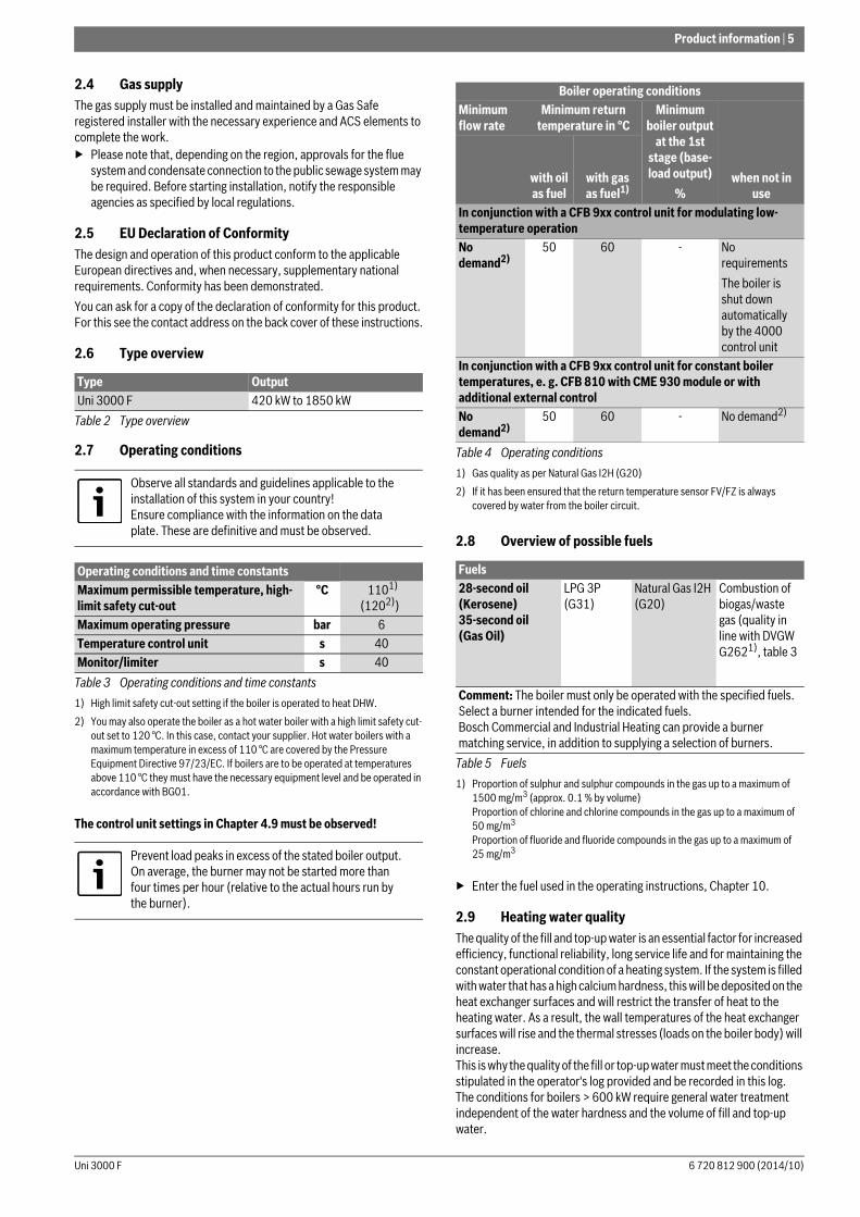
2.9 Heating water qualityThe quality of the fill and top-up water is an essential factor for increased efficiency, functional reliability, long service life and for maintaining the constant operational condition of a heating system. If the system is filled with water that has a high calcium hardness, this will be deposited on the heat exchanger surfaces and will restrict the transfer of heat to the heating water. As a result, the wall temperatures of the heat exchanger surfaces will rise and the thermal stresses (loads on the boiler body) will increase.This is why the quality of the fill or top-up water must meet the conditions stipulated in the operator's log provided and be recorded in this log.The conditions for boilers > 600 kW require general water treatment independent of the water hardness and the volume of fill and top-up water.
Type OutputUni 3000 F 420 kW to 1850 kW
Table 2 Type overview
Observe all standards and guidelines applicable to the installation of this system in your country!Ensure compliance with the information on the data plate. These are definitive and must be observed.
Operating conditions and time constantsMaximum permissible temperature, high-limit safety cut-out
°C 1101) (1202))
1) High limit safety cut-out setting if the boiler is operated to heat DHW. 2) You may also operate the boiler as a hot water boiler with a high limit safety cut-
out set to 120 °C. In this case, contact your supplier. Hot water boilers with a maximum temperature in excess of 110 °C are covered by the Pressure Equipment Directive 97/23/EC. If boilers are to be operated at temperatures above 110 °C they must have the necessary equipment level and be operated in accordance with BG01.
Maximum operating pressure bar 6Temperature control unit s 40Monitor/limiter s 40
Table 3 Operating conditions and time constants
Prevent load peaks in excess of the stated boiler output. On average, the burner may not be started more than four times per hour (relative to the actual hours run by the burner).
Boiler operating conditionsMinimum flow rate
Minimum return temperature in °C
Minimum boiler output
at the 1st stage (base-load output)
%when not in
usewith oil as fuel
with gas as fuel1)
1) Gas quality as per Natural Gas I2H (G20)
In conjunction with a CFB 9xx control unit for modulating low-temperature operationNo demand2)
2) If it has been ensured that the return temperature sensor FV/FZ is always covered by water from the boiler circuit.
50 60 - No requirementsThe boiler is shut down automatically by the 4000 control unit
In conjunction with a CFB 9xx control unit for constant boiler temperatures, e. g. CFB 810 with CME 930 module or with additional external controlNo demand2)
50 60 - No demand2)
Table 4 Operating conditions
Fuels28-second oil (Kerosene) 35-second oil (Gas Oil)
LPG 3P (G31)
Natural Gas I2H (G20)
Combustion of biogas/waste gas (quality in line with DVGW G2621), table 3
1) Proportion of sulphur and sulphur compounds in the gas up to a maximum of 1500 mg/m3 (approx. 0.1 % by volume) Proportion of chlorine and chlorine compounds in the gas up to a maximum of 50 mg/m3 Proportion of fluoride and fluoride compounds in the gas up to a maximum of 25 mg/m3
Comment: The boiler must only be operated with the specified fuels. Select a burner intended for the indicated fuels. Bosch Commercial and Industrial Heating can provide a burner matching service, in addition to supplying a selection of burners.
Table 5 Fuels
6 720 812 900 (2014/10)Uni 3000 F

6 | Product information
2.10 Using antifreeze
Antifreeze based on glycol has been used in heating systems for many years, for example Antifrogen N manufactured by Clariant.The use of other types of antifreeze should not be a cause for concern if the product is comparable with Antifrogen N.Observe the antifreeze manufacturer's instructions. Follow the manufacturer's details regarding mixing ratios.The specific thermal capacity of Antifrogen N antifreeze is lower than the specific thermal capacity of water. To enable the transfer of the required heat output, increase the required flow rate accordingly. This should be taken into account when sizing the system components (e.g. pumps) and the pipework.As the heat transfer medium has a higher viscosity and density than water, take the higher pressure drop through the pipework and other system components into account. Check the resistance of all plastic or non-metallic components in the system separately.
2.11 Pressure maintenance▶ Size the expansion vessels correctly.▶ Set the pre-charge pressures correctly.If using pump-controlled pressurisation units, pressure fluctuations will result. They can occur very frequently depending on the design of the system and the appliance settings. Even if these pressure fluctuations appear small, if they occur very frequently they may cause considerable damage to the boiler, as it is designed for a predominantly static pressure load.
To protect against damage:▶ Ensure that every heat source is equipped with an individual
expansion vessel.▶ Set the pre-charge pressure of the expansion vessel correctly.
2.12 Data plateThe data plate is located on the rear side of the boiler.There you will find information such as the serial number, output and approval details.
2.13 Tools, materials and assembly aidsFor the installation and maintenance of the boiler, standard tools are required, as used for heating, gas, water and electrical installations.
2.14 Description of applianceThe Uni 3000 F is a stationary floor-standing boiler with dual-flue combustion to EN 303/ EN 14394 for use with oil and gas as fuel. It is referred to in this manual as the floor-standing boiler or the boiler. The boiler must be fitted with a burner suitable for the boiler output. The boiler is supplied with the boiler casing mounted.For optional accessories, contact your local Bosch Commercial and Industrial Heating representative.
The boiler consists of the following main components:• The boiler shell transfers the heat generated by the burner to the
heating water.• Boiler casing and thermal insulation [2].
The boiler jacket and thermal insulation reduce heat losses.• Control unit (accessory [1]).
The control unit monitors and controls all electrical boiler components.
Fig. 1 Uni 3000 F oil/gas floor-standing boiler 420 kW-1200 kW (1040 kW-1200 kW control unit placed on side of boiler)
[1] Control unit (accessory)[2] Boiler jacket[3] Base frame[4] Burner door
Chemical additives that are not certified as harmless by the manufacturer must not be used.
Boiler output (kW)Diaphragm expansion vessel Capacity in litres
up to 500 80up to 1 000 140up to 2 000 300up to 5 000 800up to 10 000 1600
Table 6 Minimum expansion vessel sizes
Please quote these details if you have to contact the manufacturer because of a problem with your heating appliance or accessories.
NOTICE: Risk of system damage from incorrect burner matching.▶ Only use burners that meet the technical
requirements of the boiler and match the boiler output ( Chapter 2.16, page 8).
6 720 806 032-01.1ITL
4 3
1
2
Uni 3000 F6 720 812 900 (2014/10)

Product information | 7
Fig. 2 Uni 3000 F oil/gas floor-standing boiler 1400 kW-1850 kW
[1] Control unit (accessory)[2] Boiler jacket[3] Base frame[4] Burner door
2.15 Standard delivery▶ On delivery, check that all packaging is in good condition.▶ Check the delivery is complete.• Boiler with turbulators and an undrilled burner plate• Control unit retainer and cable conduit • Insulating rings for blast tube • Technical documentation• Cleaning brush• Burner cable for first burner stage
2.15.1 Required accessoriesThe following accessories are not part of the standard delivery, but are required to operate the boiler:• Burner suitable for the boiler output• Control unit with burner cable for second burner stage• Safety equipment• Boiler safety assembly• Burner plate suitable for the burner
2.15.2 Optional accessories• Sound insulation strips For additional accessories, please contact your local Bosch Commercial and Industrial Heating representative.
6 720 806 032-02.1ITL
4 3
1
2
6 720 812 900 (2014/10)Uni 3000 F

8 | Product information
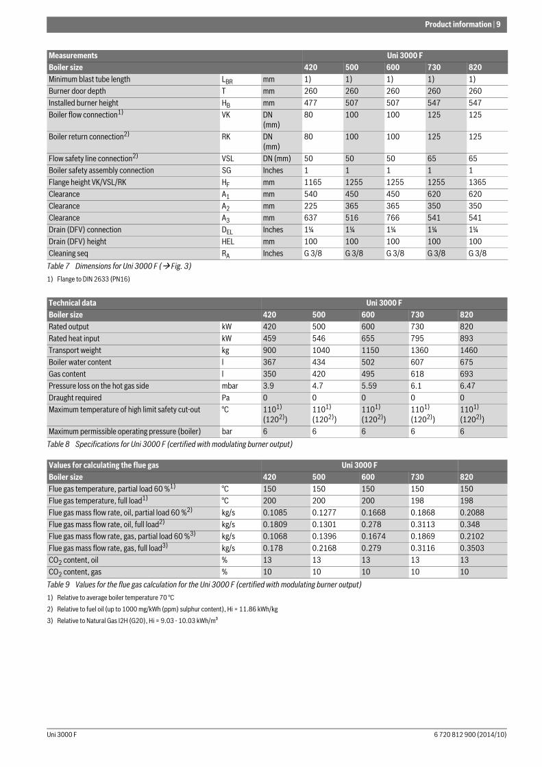
2.16 Specifications, dimensions and values for the flue gas calculation
Fig. 3 Dimensions, Uni 3000 F 420 kW to 820 kW
Fig. 4 Dimensions, burner door and burner, Uni 3000 F1)
1) The blast tube must protrude beyond the lining in the burner door.
Measurements Uni 3000 FBoiler size 420 500 600 730 820Boiler length LG mm 2142 2075 2320 2270 2469Boiler width (overall) BG mm 955 1040 1040 1040 1040Base frame length LGR mm 1573 1503 1753 1700 1900Swivelling range of the burner door BT mm 860 950 950 1060 1060Base frame width BGR mm 480 570 570 650 650Overall height (with control unit) H mm 1320 1430 1430 1430 1430Boiler height HK mm 1100 1210 1210 1320 1320Flue outlet diameter DAA mm 250 300 300 350 350Flue outlet height HAA mm 632 662 662 727 727Combustion chamber length LFR mm 1460 1390 1640 1585 1785Combustion chamber diameter DFR mm 488 548 548 624 624Minimum blast tube diameter DMB mm 290 290 290 350 350
Table 7 Dimensions for Uni 3000 F ( Fig. 3)
RA
HB
HKH
BGR LGR
RK
A
AA
3A1
VK VSL
A2
LG
HEL
HAA
HF
DEL
6 720 806 032-18.2ITL
BG
DMB
6 720 806 032-42.2ITL
DFR
T
LFR
LBR
Uni 3000 F6 720 812 900 (2014/10)
Product information | 9
Minimum blast tube length LBR mm 1) 1) 1) 1) 1)Burner door depth T mm 260 260 260 260 260Installed burner height HB mm 477 507 507 547 547Boiler flow connection1) VK DN
(mm)80 100 100 125 125
Boiler return connection2) RK DN(mm)
80 100 100 125 125
Flow safety line connection2) VSL DN (mm) 50 50 50 65 65Boiler safety assembly connection SG Inches 1 1 1 1 1Flange height VK/VSL/RK HF mm 1165 1255 1255 1255 1365Clearance A1 mm 540 450 450 620 620Clearance A2 mm 225 365 365 350 350Clearance A3 mm 637 516 766 541 541Drain (DFV) connection DEL Inches 1¼ 1¼ 1¼ 1¼ 1¼Drain (DFV) height HEL mm 100 100 100 100 100Cleaning seq RA Inches G 3/8 G 3/8 G 3/8 G 3/8 G 3/8
1) Flange to DIN 2633 (PN16)
Technical data Uni 3000 FBoiler size 420 500 600 730 820Rated output kW 420 500 600 730 820Rated heat input kW 459 546 655 795 893Transport weight kg 900 1040 1150 1360 1460Boiler water content l 367 434 502 607 675Gas content l 350 420 495 618 693Pressure loss on the hot gas side mbar 3.9 4.7 5.59 6.1 6.47Draught required Pa 0 0 0 0 0Maximum temperature of high limit safety cut-out °C 1101)
(1202))1101)
(1202))1101)
(1202))1101)
(1202))1101)
(1202))Maximum permissible operating pressure (boiler) bar 6 6 6 6 6
Table 8 Specifications for Uni 3000 F (certified with modulating burner output)
Values for calculating the flue gas Uni 3000 FBoiler size 420 500 600 730 820Flue gas temperature, partial load 60 %1)
1) Relative to average boiler temperature 70 °C
°C 150 150 150 150 150Flue gas temperature, full load1) °C 200 200 200 198 198Flue gas mass flow rate, oil, partial load 60 %2)
2) Relative to fuel oil (up to 1000 mg/kWh (ppm) sulphur content), Hi = 11.86 kWh/kg
kg/s 0.1085 0.1277 0.1668 0.1868 0.2088Flue gas mass flow rate, oil, full load2) kg/s 0.1809 0.1301 0.278 0.3113 0.348Flue gas mass flow rate, gas, partial load 60 %3)
3) Relative to Natural Gas I2H (G20), Hi = 9.03 - 10.03 kWh/m³
kg/s 0.1068 0.1396 0.1674 0.1869 0.2102 Flue gas mass flow rate, gas, full load3) kg/s 0.178 0.2168 0.279 0.3116 0.3503CO2 content, oil % 13 13 13 13 13CO2 content, gas % 10 10 10 10 10
Table 9 Values for the flue gas calculation for the Uni 3000 F (certified with modulating burner output)
Measurements Uni 3000 FBoiler size 420 500 600 730 820
Table 7 Dimensions for Uni 3000 F ( Fig. 3)
6 720 812 900 (2014/10)Uni 3000 F

10 | Product information
Fig. 5 Dimensions, Uni 3000 F 1040 and 1200 kW
Fig. 6 Dimensions, Uni 3000 F 1400 kW and 1850 kW
Fig. 7 Dimensions, burner door and burner, Uni 3000 F1)
HB
HK H
BGR LGR
VK
A1A2
VSLRKSG
A3
LG
HE
L
HA
A
HF
DEL
DAA
6 720 806 032-46.1ITL
RA
BK
BG
SG
HB
HK H
BGR LGR
VK
A1A2
VSLRK
A3
LG
HE
L
HA
A
HF
DEL
DAA
6 720 806 032-39.2ITL
RA
BK
BG
DMB
6 720 806 032-43.2ITL
DFR
T
LFR
LBR
1) The blast tube must protrude beyond the lining in the burner door.
Uni 3000 F6 720 812 900 (2014/10)

Product information | 11
Measurements Uni 3000 FBoiler size 1040 1200 1400 1850Boiler length LG mm 2600 2882 3050 3340Boiler width (overall) BG mm 1470 1470 1610 1730Boiler width BK mm 1250 1250 1390 1510Swivelling range of the burner door BT mm 1170 1170 1280 1385Base frame length LGR mm 1960 2260 2316 2720Base frame width BGR mm 820 820 880 860Overall height H mm 1475 1475 1612 1730Boiler height HK mm 1340 1340 1460 1545Flue outlet diameter DAA mm 350 350 400 400Flue outlet height HAA mm 797 797 1070 1145Combustion chamber length LFR mm 1845 2145 2120 2520Combustion chamber diameter DFR mm 710 710 780 860Maximum blast tube diameter DMB mm 350 350 350 350Minimum blast tube length LBR mm 1)
1) The blast tube must protrude beyond the lining in the burner door.
1) 1) 1)
Burner door depth T mm 260 260 300 320Burner height HB mm 592 592 635 685Boiler flow connection2)
2) Flange to DIN 2633 (PN16)
VK DN (mm) 125 125 150 200Boiler return connection2) RK DN (mm) 125 125 150 200Flow safety line connection2) VSL DN (mm) 80 80 80 100Boiler safety assembly connection SG Inches 1 1 1 1Flange height VK/VSL/RK HF mm 1475 1475 1612 1732Clearance A1 mm 620 620 725 925Clearance A2 mm 595 595 725 925Clearance A3 mm 569 870 673 670Drain & fill valve (DFV) connection DEL Inches 1¼ 1¼ 1½ 1½Drain & fill valve (DFV) height HEL mm 100 100 100 100Cleaning seq RA Inches G ½ G ½ G ½ G ½
Table 10 Dimensions for Uni 3000 F ( Fig. 6, page 10)
Technical data Uni 3000 FBoiler size 1040 1200 1400 1850Rated output kW 1040 1200 1400 1850Rated heat input kW 1138 1313 1532 2024Transport weight kg 1790 2070 2660 3600Boiler water content l 822 942 1339 1655Gas content l 934 1071 1275 1710Pressure loss on the hot gas side mbar 7.25 7.74 7.13 9.17Draught required Pa 0 0 0 0Maximum temperature of high limit safety cut-out °C 1101)
(1202))
1) High limit safety cut-out setting if the boiler is operated to heat DHW. 2) You may also operate the boiler as a hot water boiler with a high limit safety cut-out set to 120 °C. In this case, contact your supplier. Hot water boilers with a maximum
temperature in excess of 110 °C are covered by the Pressure Equipment Directive 97/23/EC. If boilers are to be operated above 110 °C they must have the necessary equipment level and be operated in accordance with BG01.
1101)
(1202)) 1101)
(1202))1101)
(1202)) Maximum permissible operating pressure (boiler) bar 6 6 6 6
Table 11 Specifications for Uni 3000 F (certified with modulating burner output)
6 720 812 900 (2014/10)Uni 3000 F

12 | Product information
Values for calculating the flue gas Uni 3000 FBoiler size 1040 1200 1400 1850Flue gas temperature, partial load 60 %1)
1) Relative to average boiler temperature 70 °C
°C 150 150 150 150Flue gas temperature, full load 1) °C 198 195 195 195Flue gas mass flow rate, oil, partial load 60 %2)
2) Relative to fuel oil (up to 1000 mg/kWh (ppm) sulphur content), Hi = 11.86 kWh/kg
kg/s 0.2651 0.3049 0.3571 0.4725Flue gas mass flow rate, oil, full load 2) kg/s 0.4418 0.5082 0.5952 0.7875Flue gas mass flow rate. Gas partial load 60 % 3)
3) Relative to Natural Gas I2H (G20), Hi = 9.03 -10.03 kWh/m³
kg/s 0.2671 0.3089 0.36 0.4761Flue gas mass flow rate, gas, full load 3) kg/s 0.4451 0.5148 0.5999 0.7935CO2 content, oil % 13 13 13 13CO2 content, gas % 10 10 10 10
Table 12 Values for the flue gas calculation for Uni 3000 F (certified with modulating burner output)
Uni 3000 F6 720 812 900 (2014/10)

Handling | 13
3 Handling
Securing the loadTo secure the load during transportation:▶ Never pull retaining straps (fixing straps, chains) over the boiler
casing.▶ Secure retaining straps only to the locking lugs.
3.1 Transporting the boiler with a forklift truckYou can transport the boiler with a forklift truck. When transporting the boiler, observe the following instructions:
▶ Transport the boiler with the forks inserted into the openings in the base frame ( Fig. 8, [2]).
Fig. 8 Transporting the boiler with a forklift truck
[1] Base frame[2] Transport openings for forklift truck[3] Boiler body
3.2 Transporting the boiler on rollers▶ Insert pipes ( Fig. 9, [2]). ▶ Lift the boiler with a car jack.▶ Place pipes underneath.
Fig. 9 Transporting the boiler on rollers
[1] Base frame[2] Pipes[3] Car jack (check jack specification for suitability)
DANGER: Risk to life through incorrectly secured boiler.▶ Use suitable means to transport the boiler (e.g. a
forklift truck, crane or heavy-duty rollers). ▶ When transporting, secure the boiler to prevent it
falling.
DANGER: Risk to life through falling load.▶ Secure the boiler with safety straps prior to
transportation.
DANGER: Risk to life through falling load.▶ Distribute the boiler weight evenly across the forklift
truck's forks when lifting and transporting the boiler.▶ Observe the weight of the boiler and that of the
means of transport.▶ When transporting, secure the boiler to prevent it
falling.▶ Use the openings provided for a forklift truck
( Fig. 8, [2]).
NOTICE: Risk of boiler damage from a damaged boiler shell.▶ Lift the boiler only by means of the base frame, not
the boiler shell or boiler door.▶ Transport the boiler with the forks of the forklift truck
inserted from the side.
1
3
2
6 720 806 032-22.1ITL
6 720 806 032-44.1ITL
23
1
6 720 812 900 (2014/10)Uni 3000 F

14 | Mounting
3.3 Lifting the boiler with a craneYou can lift and transport the boiler with a crane ( Fig. 10, [1]).
▶ Insert the hooks on the transport chain [3] into the holes of the four gusset plates [4] on the boiler body.
▶ Attach the lifting hook of the crane [2] to the lifting rope.
Fig. 10 Lifting the boiler with a crane
[1] Boiler[2] Crane hooks with safety mechanisms[3] Hook of lifting rope[4] Gusset plates (Installation location depends on the boiler size)
4 Mounting
4.1 Installing the boiler
Installation room requirements:• The support surface must provide sufficient load-bearing capacity
and solidity.• The installation room must be dry and free from the risk of frost.• The size of the installation room must be adequate to ensure correct
operation.
Minimum wall clearancesObserve the specified minimum wall clearances for the foundations or installation surface ( Fig. 11, and Tab. 13). The surface on which the boiler is to be positioned must be of load-bearing capacity, even and level. The front edge of the boiler should be flush with the edge of the foundation.Fig. 11 shows an installation example.The burner door closure can be fitted to the left or right ( Chapter 4.5 from page 18).Boiler dimension data can be found in Chapter 2.16, page 8.
DANGER: Risk to life through falling load.▶ Only use lifting ropes of the same length.▶ Only use lifting ropes that are in perfect condition.▶ Hook lifting tackle only into the lifting eyes provided
in the gusset plates on top of the boiler.▶ Never hook lifting tackle into the locking lugs on
the side of the boiler, or into the connectors.▶ Lift the boiler with a crane only if you are suitably
qualified to operate the crane.▶ Never lift the boiler with a crane on its side or on end.
Never use the locking lugs for lifting.
3
1
4
4
6 720 806 032-23.1ITL
< 90°_
2
Regarding installation and operation of your heating system, observe all relevant national standards and guidelines. The information on the data plate is binding and must be observed.
DANGER: Risk to life through poisoning!Insufficient ventilation can lead to dangerous flue gas leaks!▶ Never close off or reduce the size of ventilation and
extract air vents.▶ Never operate the boiler unless faults are rectified
immediately. ▶ Inform the operator in writing of any faults and their
associated risks.
DANGER: Risk of fire through flammable materials or liquids.▶ Never store flammable materials or liquids in the
immediate vicinity of the heat source.
NOTICE: Risk of system damage through frost.▶ Position the boiler in a room free from the risk of frost.
Boiler Boiler sizeClearance AH in mm
Clearance AV in mm1)
1) Observe dimension LBR (burner length) and dimension BT (swivelling range of the burner door, Tab. 7, page 8 and Tab. 10, page 11) in relation to clearances AV and AS (on the closure side of the burner door).
Clearance AS in mm1)
Uni 3000 F 420 -1850 1000 2500 250+LBR2)
2) On the Uni 3000 F, observe the dimension of the particular control unit with regard to the minimum clearance AS (on the installation side of the control unit 250+LBR). On the side where the burner door is not hinged, only observe 250mm clearance. If the hinge arrangement may change following installation please observe the LBR dimension.
Table 13 Specified wall clearances
Uni 3000 F6 720 812 900 (2014/10)

Mounting | 15
Fig. 11 Boiler room with boiler (dimensions in mm)
4.2 Levelling the boilerThe boiler must be levelled in the lengthwise and crosswise directions to prevent air pockets forming inside.
▶ Level the boiler [2] both horizontally and vertically using a spirit level [1].
Fig. 12 Levelling the boiler
[1] Spirit levels[2] Boiler
4.3 Fitting sound insulation strips (accessory)
To reduce noise, sound-absorbing strips (optional accessory) can be placed under the base frame, flush with the front and back of the boiler.▶ Position the boiler at its installation site.▶ Place sound insulation strips lengthways below the boiler frame at all
four corners.▶ Carefully set the boiler down.
Fig. 13 Positioning the sound insulation strips
[1] Sound insulation strips
Allow extra space if a flue silencer and/or a flue gas heat exchanger is to be installed.
Where a separation between the installation site and the boiler is required to prevent the transfer of structure-borne noise, fit these anti-vibration measures (e.g. anti-vibration supports) prior to boiler installation.
Use metal shims to level the boiler.
AV
ASAH
6 720 806 032-19.2ITL
AS
L BR
DANGER: Injury from crushing.
Consider additional sound insulation measures before installing the boiler.
6 720 806 032-24.1ITL
2
1
1
1
1
6 720 806 032-38.1ITL
6 720 812 900 (2014/10)Uni 3000 F

16 | Mounting
4.4 Flue gas and water connections for heating system
4.4.1 General requirements of the flue systemThe following recommendations pertaining to the implementation of flue systems should guarantee trouble-free operation of a combustion system. Failure to observe these rules can result in substantial operating problems during combustion and may even result in explosions. Possible problems frequently include acoustic disturbances, compromised combustion stability or excessive vibrations on assemblies or their components. Low NOx combustion systems are to be viewed as being more sensitive to operating faults on account of their combustion control. Therefore, engineer and implement the flue system with particular care.Commonly, the flue system comprises a connection piece between the heat source and the vertical flue system itself (chimney).When sizing and implementing the flue system, comply with the following requirements:• Size flue systems in accordance with the respective national and
local regulations and applicable standards. For instance, free-standing chimneys, fluid mechanical calculation (for examples of pertinent standards, see Chapter 2.1, page 4). The implementation of the flue system must comply with local Building Regulations. Observe country-specific regulations.
• When selecting the material for a flue system, take the composition and temperatures of the flue gases into account to prevent damage and contamination of the flue parts that are in contact with flue gas.
• Route flue gases as directly as possible to the chimney considering the best possible flow characteristics (e.g. short and with a gradient and the fewest possible deviations). Provide a separate chimney flue for each boiler. Take the thermal expansion of the system into account.
• Implement deviations in the connection pieces, such as bends or deflectors, so as to minimise flow resistance. Connection pieces with several deviations should be avoided, as they would have a detrimental effect on air-borne and structure-borne noise as well as the start-up pressure hammer. Prevent sharp-edged joints between rectangular connection flanges and the connection pipe. The joint angle should not exceed 30°, the same as for any reducers/expansions that may be required.
• Where possible, connection pieces should be joined to the chimney to provide optimum flow characteristics and with an incline (at an angle less than 45°). Any terminal pieces at the chimney outlet must ensure the free discharge of flue gas into the open air.
• Any condensate must be able to drain freely over the entire length of its discharge pipework and drained off in accordance with local regulations.
• Inspection apertures should be provided in compliance with local regulations, possibly after discussion with the responsible Local Authority inspector.
• The chimney must be separated from the boiler system (e.g. with compensators) to interrupt transfer of structure-borne noise.
• Where a flue gas damper is set into a flue system, an “OPEN” safety limit switch must be integrated into the boiler control. Combustion must only be able to start when the feedback from the limit switch confirms that the flue damper is fully open. A temperature drop inside the boiler is possible on account of the time it takes the actuator to move the damper into position. Implement the end position CLOSED at the flue damper so that the flue damper never closes fully. This prevents damage to the fitted burner through heat build up.
4.4.2 Fitting a sealing collar (accessory)▶ Fit the sealing collar in accordance with the installation instructions
supplied.
4.4.3 Connecting the boiler to the pipeworkObserve the following information for connecting the boiler to the pipework. This is important to ensure trouble-free operation.
Connecting the heating return
▶ Connect the heating system return to the boiler return connection ( Fig. 14 and Fig. 15 [3]).
Fig. 14 Uni 3000 F 420 kW to 1200 kW boiler (left = rear of boiler)
[1] Boiler flow connection (VK)[2] Safety flow line (VSL - connection for an on-site safety valve)[3] Boiler return connection (RK)[4] Test point (sensor well 3/4") for 190 kW to 1200 kW
DANGER: Risk to life through poisoning!Insufficient ventilation can lead to dangerous flue gas leaks!▶ Never operate the boiler unless faults are rectified
immediately.▶ Inform the operator in writing of any faults and their
associated risks. Boiler contamination on the water side is not permitted. To prevent contamination on the water side, we recommend the installation of an air/dirt separator in the return.
NOTICE: Risk of system damage from leaking connections.▶ Install all lines free from stress to the boiler
connections.
NOTICE: Risk of system damage from too low a return temperature.▶ Observe the operating conditions ( Tab. 4,
page 5). Back-end Protection must be designed into the hydraulic arrangement.
6 720 806 032-05.1ITL
12
3
45
Uni 3000 F6 720 812 900 (2014/10)
Mounting | 17
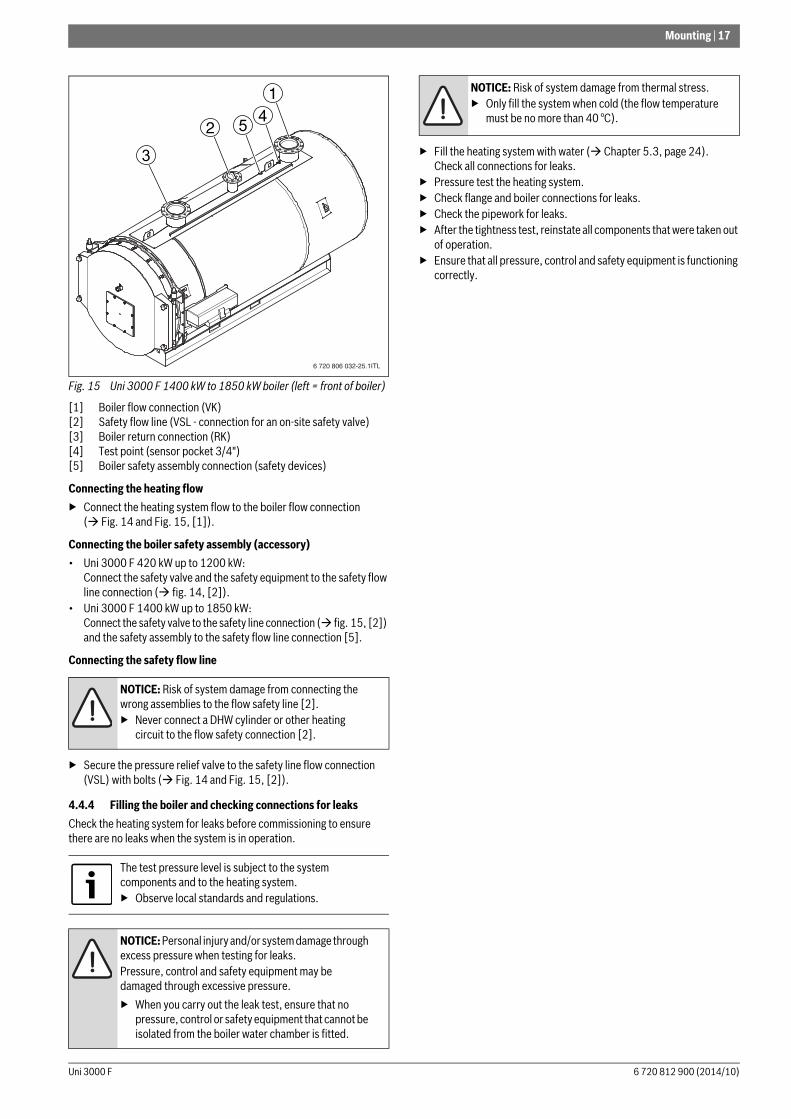
Fig. 15 Uni 3000 F 1400 kW to 1850 kW boiler (left = front of boiler)
[1] Boiler flow connection (VK)[2] Safety flow line (VSL - connection for an on-site safety valve)[3] Boiler return connection (RK)[4] Test point (sensor pocket 3/4")[5] Boiler safety assembly connection (safety devices)
Connecting the heating flow▶ Connect the heating system flow to the boiler flow connection
( Fig. 14 and Fig. 15, [1]).
Connecting the boiler safety assembly (accessory)• Uni 3000 F 420 kW up to 1200 kW:
Connect the safety valve and the safety equipment to the safety flow line connection ( fig. 14, [2]).
• Uni 3000 F 1400 kW up to 1850 kW: Connect the safety valve to the safety line connection ( fig. 15, [2]) and the safety assembly to the safety flow line connection [5].
Connecting the safety flow line
▶ Secure the pressure relief valve to the safety line flow connection (VSL) with bolts ( Fig. 14 and Fig. 15, [2]).
4.4.4 Filling the boiler and checking connections for leaksCheck the heating system for leaks before commissioning to ensure there are no leaks when the system is in operation.
▶ Fill the heating system with water ( Chapter 5.3, page 24). Check all connections for leaks.
▶ Pressure test the heating system.▶ Check flange and boiler connections for leaks.▶ Check the pipework for leaks.▶ After the tightness test, reinstate all components that were taken out
of operation.▶ Ensure that all pressure, control and safety equipment is functioning
correctly.
NOTICE: Risk of system damage from connecting the wrong assemblies to the flow safety line [2].▶ Never connect a DHW cylinder or other heating
circuit to the flow safety connection [2].
The test pressure level is subject to the system components and to the heating system.▶ Observe local standards and regulations.
NOTICE: Personal injury and/or system damage through excess pressure when testing for leaks.Pressure, control and safety equipment may be damaged through excessive pressure.▶ When you carry out the leak test, ensure that no
pressure, control or safety equipment that cannot be isolated from the boiler water chamber is fitted.
6 720 806 032-25.1ITL
2 5 4
3
1 NOTICE: Risk of system damage from thermal stress.▶ Only fill the system when cold (the flow temperature
must be no more than 40 °C).
6 720 812 900 (2014/10)Uni 3000 F

18 | Mounting
4.5 Opening and closing the burner door
4.5.1 Opening the burner door
The burner door can be opened either to the left or right. The following instructions assume opening to the right.▶ Left side: Loosen two nuts on the burner door [1].▶ Right side: Loosen two nuts on the burner door [1] 2 to 3 turns.▶ Left side: Lower hinges by loosening the hinge nut [2] (2 to 3 turns).
The door must no longer be in contact with the pin of the door hinge [4] ( Fig. 17). Right side: Turn the lock nut [3] 2 to 3 turns in the direction of the burner door. This pushes the burner door away from the boiler. There must be a gap of at least 5 mm between the burner door and boiler in order not to damage the gaskets.
▶ Left side: The burner door is opened by turning the lock nut [3] in the direction of the burner door. The burner door must no longer be in contact with the pin [4] of the door hinge.
▶ Open the burner door.
Fig. 16 Opening the burner door
Key to Fig. 16:[1] Nuts[2] Hinge nut[3] Lock nut[4] Hinge pin
Fig. 17 Positions of burner door and hinge pin
4.5.2 Closing the burner door▶ Left and right side: turn the lock nut [3] in the direction of the boiler.▶ Close the burner door.▶ Screw the nut ( Fig. 16, [1]) onto the hinge pin [4] and bring the
door to just before the sealing faces.▶ Left and right side: Align the sealing faces of the burner door and
boiler by tightening the hinge nuts [2] alternately.The burner door must have the same clearance (about 10 mm) from the edge of the closing face of the boiler on all sides.
▶ Left and right side: Tighten the lock nuts [1] until the burner door seals tightly on all sides.
▶ Left and right side: Secure the burner door with lock nut [3].▶ Check the tightness of the burner door (e. g. with a gas leak detection
spray).
Retighten the nuts that secure the burner door 14 days after commissioning.
WARNING: Risk of injury from falling parts.The burner door can fall off when opened.▶ Loosen the screws only on one side of the burner door.
1
1
34
2
1
6 720 806 032-28.1ITL
6 720 806 032-49.1ITL
Uni 3000 F6 720 812 900 (2014/10)

Mounting | 19
4.6 Fitting the burner (accessory)
4.6.1 Fitting the burner plate (accessory)
▶ Secure burner plate [2] with gasket [1] to burner door [3] using hexagon bolts and washers [4].
Fig. 18 Fitting the burner plate
[1] Sealing ring[2] Burner plate[3] Burner door[4] Hexagon bolt and washer
4.6.2 Fitting the burner to the burner plate
The thermal insulation in the burner door comes standard with a 200 mm hole for the blast tube. If the blast tube is larger than this, the diameter of the aperture can be increased to a maximum of 275 mm.
The burner door must be opened to allow the burner to be fitted.▶ Open the burner door ( Chapter 4.5.1).▶ Push a gasket ( Fig. 18, [1]) onto the burner connector.▶ Screw burner ( Fig. 19, [1]) to the burner plate [2].▶ Cut out insulating rings [4] in accordance with the diameter of blast
tube [5].▶ Fill remaining gap between burner door insulation [3] and blast tube
[5] with adapted insulating rings [4].
▶ Connect the blower connection for the sight glass with burner [1] to ensure the sight glass remains free from deposits.
▶ Close burner door and tighten nuts ( Chapter 4.5, page 18).▶ Connect burner cable to burner [1].
Fig. 19 Fitting the burner
[1] Burner[2] Burner plate[3] Burner door insulation[4] Insulating rings[5] Blast tube
4.7 Fitting the control unit (accessory)This chapter explains how to fit the control units of the CFB controller series and a temperature sensor set for the boiler.Depending on the boiler size, the control unit can be mounted either on top of the boiler or on the side.
4.7.1 For boiler sizes 420 kW to 820 kWIn Fig. 20, (overleaf), the control unit (without rear panel) and the control unit holder [1] are shown from the rear.▶ Undo both screws from cover [1]. Lift off the cover.▶ Place the control unit with the locking tabs [4] into the holes in the
front of the control unit holder (mounted on the front of the boiler) [5].
▶ Pull the control unit forwards and then tip backwards. The flexible hooks [2] must latch Into the openings [3].
NOTICE: Risk of system damage from incorrect burner.▶ Only use burners that meet the technical requirements
of the boiler ( Chapter 2.16, page 8).
Pre-drilled burner plates are available from the boiler manufacturer (accessory).The burner plate depends on the burner used.
Refer to the installation instructions of the particular burner for how to mount and connect it.
NOTICE: Risk of system damage from incorrect or missing insulating rings.▶ Only use the insulating rings supplied.
6 720 806 032-27.1ITL
3
1
2
4
6 720 806 032-29.1ITL
41
23
5
6 720 812 900 (2014/10)Uni 3000 F

20 | Mounting
▶ Screw the base of the control unit to the control unit holder with 2 sheet-metal screws.
Fig. 20 Fitting the control unit for boiler sizes 420 kW to 820 kW
[1] Cover[2] Flexible hooks[3] Rectangular openings in the control unit holder[4] Locking tabs[5] Oval holes in the control unit holder[6] Cable feed in the control unit holder[7] Holes for self-tapping screws
4.7.2 For boiler sizes 1040 kW to 1850 kWIn Fig. 21, page 20, the control unit is shown from the rear.▶ Undo both screws from cover [1]. Lift off cover [2] ( Fig. 20).▶ Remove both plugs ( Fig. 21, [2]) from the control unit.▶ Place the control unit ( Fig. 21, [4]) on the studs of the control unit
holder on the side of the boiler.▶ Secure the control unit by screwing screws into the mounting
holes [3] on the control unit holder.
Fig. 21 Fitting the control unit for boiler sizes 1040 kW to 1850 kW
[1] Screws[2] Plug[3] Mounting Holes[4] Control unit
4.7.3 Making the electrical connections
▶ Knock out or cut out the appropriate parts from back panel [1] ( Fig. 22) as required.
▶ Make the plug-in connection in the control unit in accordance with the labelling on the terminal strip.
▶ Route the burner cable to the control unit ( Chapter 4.8, page 21).▶ Connect the burner cable to the control unit in accordance with the
labelling on the plug-in connector strip.▶ Route the sensor leads to the control unit ( Chapter 4.8, page 21).▶ Connect the sensor leads to the control unit in accordance with the
labelling on the plug-in connector strip.▶ Route the electrical cables relevant to the heating system (for
example, sensors, pumps, actuators) to the control unit.▶ Make the on-site connections on the control unit in accordance with
the labelling on the plug-in connector strip.
▶ Make on-site electrical connections for the heating system to the appropriate plug-in connectors according to the connection diagram ( control unit documentation).
▶ Refit back panel ( Fig. 22) to the control unit.
Fig. 22 Preparing the cable entry
[1] Control unit back panel
1
2
456 376 720 615 362-18.2O
6 720 806 032-48.1ITL
2
3
4
1
DANGER: Risk to life through electric shock.▶ Prior to opening the appliance, isolate all electrical
connections and secure against unintentional reconnection.
▶ Carefully route the cables/leads and capillary tubes.▶ Only carry out electrical work if you are suitably
qualified person. If you are not suitably qualified, arrange for a suitably qualified person to make the electrical connections.
▶ Observe all relevant electrical regulations.
DANGER: Risk of fatal injury and fire from hot components.Hot components can damage the cabling.▶ Secure cable sufficiently and route in the provided
cable holding systems where necessary.▶ Route cables with a sufficient clearance from hot
components.
The positions of the terminal strips on control units are not identical. The terminal strip is easy to identify after the control unit has been opened. The labelling of the terminal strip in the various control units is identical.
6 720 615 362-19.3T1
Uni 3000 F6 720 812 900 (2014/10)

Mounting | 21
Secure all cables with cable clips (scope of delivery of the control unit). Carry out the following steps ( Fig. 23):▶ Insert the cable clip, with inserted electrical cable in place, from the
top into the slot of the clip frame (step 1).▶ Push cable clip down (step 2).▶ Push against the clip (step 3).▶ Flip the toggle up (step 4).▶ Refit the cover ( Fig. 20 and Fig. 21, page 20) to the control unit.▶ Tighten screws (Fig. 20 and Fig. 21, page 20) to secure the control
unit cover hood.
Fig. 23 Securing the electrical cable with cable clips
4.8 Installing temperature sensors
The boiler test point is located at the top of the boiler shell (location of the test point Fig. 14, page 16 and Fig. 15, page 17).
▶ Insert sensor set ( Fig. 24, page 21, [3]) into the measuring point [1] until it bottoms.
▶ Secure sensor set [3] with sensor retainer [4] in the test point.
▶ Roll up excess lengths of cables, capillaries (never kink) and sensor leads and position them on the thermal insulation of the boiler body.
Fig. 24 Installing the temperature sensor set on the Uni 3000 F (up to 1200 kW)
[1B] Test point (sensor well 3/4") for 420 kW to 1200 kW[2] Sensor well in the test point [3] Sensor set[4] Sensor retainer[5] Control unit[6] Compensating spring
NOTICE: Risk of system damage from damaged capillaries or incorrectly fitted temperature sensor!▶ Ensure that the capillaries are neither kinked nor
squashed when uncoiling and routing them.▶ Always push the temperature sensor right to the
bottom of the sensor pocket - ensuring an accurate reading.
NOTICE: Risk of system damage from incorrect sensor position!The sensors of the high limit safety cut-out (STB) and of the temperature controller (TR) must be fitted at the installation location on the top of the boiler ( Fig. 24, page 21 and Fig. 25, page 22).▶ In the case of third party control units, match the
sensor immersion sleeve to the diameter of the sensors used.
▶ Do not change the length of the immersion sleeve.
The temperature sensor of a temperature controller is marked “TR”.
Note that installation of the temperature sensor set is different when the CFB 810 control unit with the CME 930 auxiliary module is used.
6 720 615 362-20.1SL
Insert compensating spring [6] between the temperature sensors to ensure a good contact between sensor well [2] and sensor surfaces, and thereby a reliable temperature transfer.
1A
1B
6 720 812 900-16.1TL
5
2
34
6
6 720 812 900 (2014/10)Uni 3000 F

22 | Mounting
Fig. 25 Installing the temperature sensor set on the Uni 3000 F 1400 kW to 1850 kW
[1] Test point (sensor pocket 3/4") [2] Sensor well in the test point [3] Sensor set[4] Sensor retainer[5] Control unit[6] Compensating spring
When using the CFB 810 control unit with CME 930 auxiliary module:▶ Fit the temperature sensor of the CME 930 as contact sensor on site
to the boiler return using heat conducting paste and a tie.
4.9 Control unit settings
The purpose of optimum control unit settings is to achieve long burner runtimes and avoid rapid temperature changes in the boiler. Gentle temperature changes result in a longer heating system service life. The control strategy of the control unit must therefore be prevented from becoming ineffective, i.e. through the boiler water controller switching the burner on and off. ▶ Maintain the minimum differential between the selected shutdown
temperature of the high limit safety cut-out, the temperature controller, the maximum boiler water temperature and the maximum temperature demand ( Tab. 14 to 16, page 23).
▶ Select set temperatures for the heating circuits that are as low as possible.
▶ Start heating circuits (e.g. when starting up in the mornings) at 5-minute intervals.
NOTICE: Risk of system damage from incorrect sensor position.Fitting the temperature sensor elsewhere can result in system damage.▶ Install the temperature sensor of the CME 930 only in
the boiler return as the responsibility of this module is to safeguard against low return temperatures and condensing.
We recommend using a control unit from the CFB series.
1
5
2
34
6 720 812 900-36.1TL
6
The maximum boiler water temperature can be selected in the control unit (programmer) in the “Boiler parameters” menu, under menu item “Max. shutdown temperature”.
If a CFB 9xx control unit is used, burner modulation in standard mode is not enabled for 3 minutes. Never modulate upwards more quickly than this.
Adjustable parameter (max. temperature) CFB 910/CFB 930High limit safety cut-out (STB)1)
1) Set the high limit safety cut-out and temperature controller as high as possible, but ensure the settings are at least 5 K apart.
110 °C
at least 18 K
minimum 5 KTemperature controller (TR)1) 105 °C
minimum 6 KMax. boiler water temperature 99 °C
minimum 7 K Max. temperature demand2) of heating circuit3) and DHW4)
2) Both temperature demands must always be at least 7 K under the maximum boiler water temperature.
3) The temperature demand of heating circuits equipped with a mixing valve is composed of the set flow temperature and the “Boiler rise” parameter in the heating circuit data menu.
4) The temperature demand of DHW heating is composed of the set DHW temperature and the “Boiler rise” parameter in the DHW menu.
92 °C
Table 14 Adjustable parameter CFB 910/CFB 930
Adjustable parameter (max. temperature) CFB 940High limit safety cut-out (STB)1)
1) Set the high limit safety cut-out and temperature controller as high as possible, but ensure the settings are at least 5 K apart.
120 °C minimum 5 K
Temperature controller (TR)1)2)
2) The TR does not function on the CFB 940 in automatic mode.
105 °C minimum 6 K
Max. boiler water temperature 112 °C minimum 7 K
Max. temperature demand3) of heating circuit4) and DHW5)
3) Both temperature demands must always be at least 7 K under the maximum boiler water temperature.
4) The temperature demand of heating circuits equipped with an actuator is composed of the set flow temperature and the “Boiler rise” parameter in the heating circuit data menu.
5) The temperature demand of DHW heating is composed of the set DHW temperature and the “Boiler rise” parameter in the DHW menu.
105 °C
Table 15 Adjustable parameter CFB 940
Uni 3000 F6 720 812 900 (2014/10)

Mounting | 23
Settings for boiler water controller and maximum boiler water temperatureThe boiler water controller is only designed to provide emergency operation with an adjustable boiler water temperature if the control electronics fail. In standard control mode, the function of the boiler water controller is provided by the maximum boiler water temperature. The maximum boiler water temperature can be selected in the control unit in the “Boiler parameters” menu, under menu item “Max. shutdown temperature”.
Control unit settings
Fig. 26 Control unit settings, example for CFB 910
[1] High limit safety cut-out[2] Temperature control unit[3] F1, F2 Fuse[4] Programmer[5] Burner emergency operation switch[6] Appliance on/off switch▶ Set temperatures ( Tab. 14 to 16, and page 22) for high limit
safety cut-out [1] in the control unit and on the temperature controller [2] respectively.
▶ Set the maximum boiler water temperature on the programmer [4].
Example DHW demand:Sum of the set DHW temperature (60 °C) the “Boiler rise” parameter (20 °C) in the “DHW” menu:60 °C + 20 °C = Maximum temperature demand 80 °C
Example heating circuits:Sum of the set temperature of the heating circuit with mixer with the highest temperature required (70 °C) and parameter “Boiler rise” (5 °C) in the “Heating circuit data” menu:70 °C + 5 °C = Maximum temperature demand 75 °C
Notes on setting third party control units
• The third party control unit (Building Management System or PLC controllers) must ensure a maximum internal boiler water temperature that is sufficiently different from the high limit safety cut-out. It must also be ensured that the control electronics rather than the boiler water controller switch the burner on and off.
• The control unit must ensure that the burner is switched to low load before being shut down. If this is not observed, the safety shut-off valve (SAV) in the gas train may lock out.
• Select control equipment that allows a gentle start-up with a time delay when the system is cold.
• After the burner demand, an automatic timer (for example) should limit the burner to low load for a period of approx. 180 seconds. A restricted heat demand will prevent uncontrolled starting and stopping of the burner.
• It must be possible to show the number of burner starts on the control unit used (or alternatively on the burner control unit).
Adjustable parameter (max. temperature) CFB 810 with CME 930High limit safety cut-out (STB)1)
1) Set the high limit safety cut-out and temperature controller as high as possible, but ensure the settings are at least 5 K apart.
120 °C minimum 5 K
Temperature controller (TR) 105 °CTable 16 Adjustable parameter CFB 810
The maximum temperature demand is not a value that is set directly. The maximum temperature demand is composed of the set temperature and the minimum required rise.
1 2 3 4 5 66 720 806 032-47.1ITL
All maximum temperature demands must always be 7 K below the maximum selected boiler water temperature.
NOTICE: System damage due to incorrect sensor position!The sensors of the high limit safety cut-out (STB) and of the temperature controller (TR) must be fitted at the appropriate installation location on the top of the boiler.▶ In the case of third party control units, match the
sensor immersion sleeve to the diameter of the sensors used.
▶ Do not change the length of the immersion sleeve.
Observe the operating conditions in Chapter 2.7, page 5 and observe Chapter 4.8, page 21 – page 22 when installing sensors.
Unit ValueTemperature control unit s 40Monitor/limiter s 40Minimum difference between burner on and off temperatures
K 7
Table 17 Conditions of Use
6 720 812 900 (2014/10)Uni 3000 F

24 | Commissioning
5 Commissioning
▶ Complete the commissioning report ( Chapter 5.7, page 26).
5.1 CommissioningThe burner door is lined inside with insulating and refractory concrete. On account of its manufacturing technique, residual moisture will be contained in the door lining. This may evaporate during the initial operation, resulting in droplets forming on the door. Any water vapour created must be able to dissipate during the overall heat-up time. This process may take up to one week.
The heat input in the first ten hours run must not exceed 60 %. This heat-up procedure must be performed.
5.2 Flushing the heating systemFlush the heating system prior to commissioning to prevent contamination that could block or damage the circulation pump.
▶ Isolate the heating flow and return at the boiler.▶ Connect the heating flow to a drinking water connection.▶ Connect a hose to the heating return of the heating system.▶ Route hose from the heating return to a drain.▶ Open connected consumers (e.g. radiators).▶ Flush the heating system with fresh water through the flow until clear
water emerges from the heating return.▶ Drain the heating system down.
5.3 Filling the heating system
The fill and top-up water quality must comply with the specifications in the operator's log supplied.The pH value of the heating water increases after the heating system has been filled. After 3 – 6 months (initial service) check whether the pH value of the heating water has settled down.▶ Adjust the pre-charge pressure of the expansion vessel to the
required pressure (only for sealed unvented systems).▶ Open the mixing and shut-off valves on the heating water side.▶ Fill the heating system with the aid of a filling facility and observe the
pressure gauge whilst doing so.▶ Vent the heating system via the radiator air vent valves.▶ Top up with water if the water pressure drops as a result of venting
the system.
5.4 Preparing the heating system for operation
Observe the following during commissioning:▶ Before commissioning, vent the heating system via the ventilation
facilities provided for this purpose.▶ Ensure that the inspection aperture on the flue gas collector is
closed.▶ Ensure that the burner door is securely closed.▶ Ensure that the safety equipment is functioning correctly.▶ Check that the required operating pressure has been built.▶ Check the flange connections and other connections for tightness.
5.5 Commissioning the control unit and burner▶ Use the control unit to commission the boiler.▶ Set the parameters of the control unit ( Chapter 5.5.1).▶ Observe the commissioning times ( Chapter 5.1)The settings made in the control unit will affect the burner as well. The burner can then be started by the control unit. For further details, see the technical documents for the particular control unit and/or burner.
▶ Complete the commissioning report in the technical documentation of the burner.
NOTICE: Risk of boiler damage from contaminated combustion air.▶ Never operate the boiler when there is a lot of dust in
the boiler room, e.g. due to building work.▶ Ensure adequate ventilation.▶ Never use or store chlorinated cleaning agents or
halogenated hydrocarbons (as contained in spray cans, solvents or cleaning agents, paints and adhesives, for example) in the boiler room.
▶ A burner contaminated during building work must be cleaned before commissioning.
Observe control parameters and specification.
Cracks may occur during heat-up as a result of shrinkage. Small shrinkage cracks and some flaking are unavoidable and will not impair the function nor are they considered damage.
NOTICE: Risk of system damage from water vapour.If the boiler heats up too rapidly, the water vapour cannot escape through existing pores in the lining, which may result in flaking of the door insulation. This may result in a total destruction of the lining. ▶ To prevent destruction of the lining, it is essential
that the stated heat-up time and maximum heat-up output be observed.
If the heating system contains several heating circuits, these must be flushed one after the other.
NOTICE: Risk of system damage from thermal stress.▶ Only fill the heating system when cold (the flow
temperature must not exceed 40 °C).▶ Fill the heating system during operation only by a
WRAS approved filling facility in the return of the pipework for the heating system.
CAUTION: Health risk from contaminated drinking water.▶ It is essential to observe all country-specific
regulations and standards regarding the prevention of drinking water contamination. In Europe, observe standard EN 1717.
Concerning tightness on the flue gas side, a leakage rate of 2 % of the flue gas flow rate is permissible.
You have the opportunity of raising the flue gas temperature if the measurements taken for the commissioning report indicate that the flue gas temperature is too low (risk of condensate forming) for the chimney concerned ( Chapter 5.6, page 25).
Uni 3000 F6 720 812 900 (2014/10)
Commissioning | 25
5.5.1 Setting control unit parametersThe controller settings listed in Tab. 18 apply to the CFB 910 and CFB 930 control units.Make settings at the service level of the “Boiler specifications” and “Special parameters” menus.The service documentation for the control unit should be used for parameterising the CFB 940 control unit.
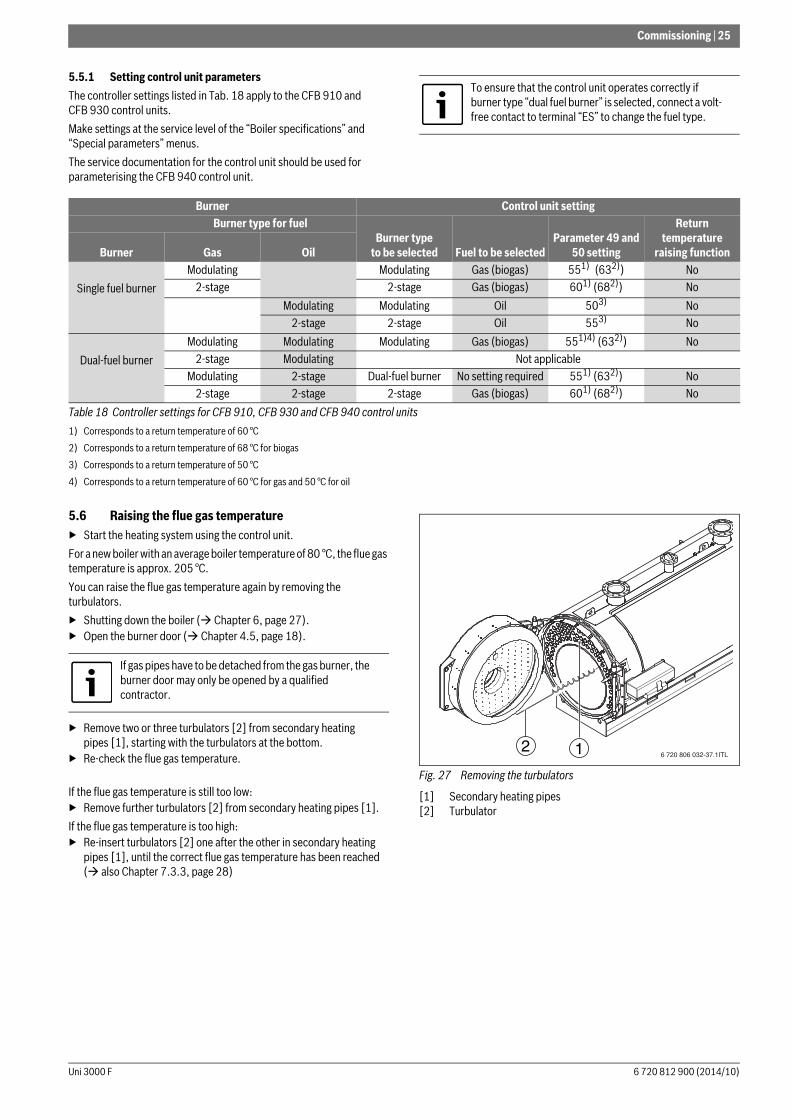
5.6 Raising the flue gas temperature▶ Start the heating system using the control unit.For a new boiler with an average boiler temperature of 80 °C, the flue gas temperature is approx. 205 °C. You can raise the flue gas temperature again by removing the turbulators.▶ Shutting down the boiler ( Chapter 6, page 27).▶ Open the burner door ( Chapter 4.5, page 18).
▶ Remove two or three turbulators [2] from secondary heating pipes [1], starting with the turbulators at the bottom.
▶ Re-check the flue gas temperature.
If the flue gas temperature is still too low:▶ Remove further turbulators [2] from secondary heating pipes [1].If the flue gas temperature is too high:▶ Re-insert turbulators [2] one after the other in secondary heating
pipes [1], until the correct flue gas temperature has been reached ( also Chapter 7.3.3, page 28)
Fig. 27 Removing the turbulators
[1] Secondary heating pipes [2] Turbulator
To ensure that the control unit operates correctly if burner type “dual fuel burner” is selected, connect a volt-free contact to terminal “ES” to change the fuel type.
Burner Control unit setting Burner type for fuel
Burner typeto be selected Fuel to be selected
Parameter 49 and 50 setting
Return temperature
raising functionBurner Gas Oil
Single fuel burnerModulating Modulating Gas (biogas) 551) (632))
1) Corresponds to a return temperature of 60 °C2) Corresponds to a return temperature of 68 °C for biogas
No2-stage 2-stage Gas (biogas) 601) (682)) No
Modulating Modulating Oil 503)
3) Corresponds to a return temperature of 50 °C
No2-stage 2-stage Oil 553) No
Dual-fuel burnerModulating Modulating Modulating Gas (biogas) 551)4) (632))
4) Corresponds to a return temperature of 60 °C for gas and 50 °C for oil
No2-stage Modulating Not applicable
Modulating 2-stage Dual-fuel burner No setting required 551) (632)) No2-stage 2-stage 2-stage Gas (biogas) 601) (682)) No
Table 18 Controller settings for CFB 910, CFB 930 and CFB 940 control units
If gas pipes have to be detached from the gas burner, the burner door may only be opened by a qualified contractor.
6 720 806 032-37.1ITL12
6 720 812 900 (2014/10)Uni 3000 F
26 | Commissioning
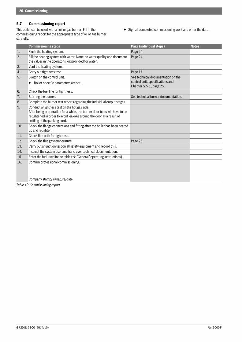
5.7 Commissioning reportThis boiler can be used with an oil or gas burner. Fill in the commissioning report for the appropriate type of oil or gas burner carefully.
▶ Sign all completed commissioning work and enter the date.
Commissioning steps Page (individual steps) Notes 1. Flush the heating system. Page 242. Fill the heating system with water. Note the water quality and document
the values in the operator's log provided for water. Page 24
3. Vent the heating system.4. Carry out tightness test. Page 175. Switch on the control unit.
▶ Boiler-specific parameters are set.See technical documentation on the control unit, specifications and Chapter 5.5.1, page 25.
6. Check the fuel line for tightness.7. Starting the burner. See technical burner documentation.8. Complete the burner test report regarding the individual output stages.9. Conduct a tightness test on the hot gas side.
After being in operation for a while, the burner door bolts will have to be retightened in order to avoid leakage around the door as a result of settling of the packing cord.
10. Check the flange connections and fitting after the boiler has been heated up and retighten.
11. Check flue path for tightness.12. Check the flue gas temperature. Page 2513. Carry out a function test on all safety equipment and record this.14. Instruct the system user and hand over technical documentation.15. Enter the fuel used in the table ( “General” operating instructions).16. Confirm professional commissioning.
Company stamp/signature/dateTable 19 Commissioning report
Uni 3000 F6 720 812 900 (2014/10)

Shutting down | 27
6 Shutting down
6.1 Shutting down the heating systemShut down your heating system via the control unit. This also switches the burner off automatically.▶ Place the operating mode selector switch on the control unit in the
“0” (Off) position.▶ Isolate the fuel supply to the burner.
6.2 Shutting down the heating system in an emergency
▶ Never put your life at risk. Your own safety is paramount.▶ In dangerous situations, immediately close the main fuel shut-off
valve and the power supply of the heating system via the boiler room Main Circuit Board/fuse or the heating system emergency stop switch.
▶ Isolate the fuel supply to the burner.▶ Guard against unintentional reconnection.
7 Inspection and maintenance
7.1 General notesOffer your customer an annual contract covering inspection and responsive service. For the work covered by such a contract see Chapter 7.5 “Inspection and maintenance reports”, page 31.
7.2 Preparing the boiler for inspection and maintenance▶ Shut down the heating system ( Chapter 6.1, page 27).
Before opening the burner door:▶ Check the general condition of the heating system.▶ Visual inspection and function check of the heating system.▶ Check all system parts that carry fuel or water for leaks and visible
corrosion.▶ Open the burner door ( Chapter 4.5, page 18).
NOTICE: Risk of system damage through frost.When there is a frost, your heating system can freeze up if it is shut down, e.g. through a fault shutdown.▶ When there is a risk of frost, protect your heating
system against freezing up.▶ If your heating system has been shut down for
several days due to a fault shutdown and there is a risk of frost, drain the heating water at the drain & fill valve. Also leave the air vent valve at the highest point in the system open.
NOTICE: System damage due to frost.The heating system can freeze up as a result of a power failure or if the power has been switched off.▶ Check the “Control unit settings” to ensure the
system remains operational (especially when there is a risk of frost).
Only in emergencies, switch OFF the heating system via the boiler room Main Circuit Board/fuse or the heating system emergency stop switch.
NOTICE: System damage due to inadequate cleaning and maintenance.▶ Carry out cleaning and maintenance at least once a
year. Check that the complete heating system operates correctly.
▶ Immediately correct all faults to prevent system damage.
Annual inspection and service are part of the warranty terms.
Use only original spare parts from the manufacturer. Spare parts can be ordered via spare parts merchants. A genuine spare parts list is available online (see last page for details).
DANGER: Risk to life from electric shock when the heating system is live.▶ Prior to opening the heating system: Isolate the
heating system from the mains power supply via the heating system emergency stop switch or the corresponding Main Circuit Board/fuse.
▶ Secure the heating system against unintentional reconnection.
DANGER: Risk to life from the explosion of flammable gases.▶ Work on gas components must only be carried out by
qualified and authorised Gas Safe and ACS accredited contractors.
If gas pipes have to be detached from the gas burner, the burner door may only be opened by a qualified contractor.
6 720 812 900 (2014/10)Uni 3000 F

28 | Inspection and maintenance
7.3 Cleaning the boiler
7.3.1 Cleaning heating surfaces and turbulators with a cleaning brush
▶ Remove turbulators [4] from secondary heating pipes [1].▶ Clean turbulators [4].▶ Push the bristle part of the cleaning brush [3] right through the
secondary heating pipe until the bristles emerge at the other end of the pipe. The internal surface of the pipe must be cleaned thoroughly.
▶ Clean the heating surfaces in combustion chamber [2] and the heating surfaces in secondary heating pipes [1] with cleaning brush [3].
Fig. 28 Cleaning the heating surfaces
[1] Secondary heating pipes[2] Combustion chamber (heating surfaces of combustion chamber)[3] Cleaning brush[4] Turbulator
7.3.2 Cleaning the flue gas collectorTo be able to remove combustion residues from the flue gas collector, first remove the cleaning cover. The cleaning cover is located on the rear of the boiler [2].
Fig. 29 Opening the cleaning cover of the flue gas collector
[1] Back panel[2] Cleaning cover▶ Remove nuts and washers from the cleaning cover [2].▶ Remove the cleaning cover of flue gas collector [2].▶ Remove the loosened combustion residues from the combustion
chamber ( Fig. 28), the hot gas flue and the flue gas collector as well as the condensate hose.
7.3.3 Inserting turbulators
CAUTION: Risk of injury through falling parts!▶ Prior to opening the doors, ensure that the hinge pin
is correctly fitted in the burner door and secured with a nut.
WARNING: Risk of system damage from using incorrect cleaning equipment.▶ If cleaning with a brush, use only genuine cleaning
brushes from the manufacturer. Brush included in scope of delivery.
6 720 806 032-30.1ITL
4 23
1
NOTICE: Risk of system damage from improperly inserted turbulators.Incorrectly inserted turbulators impede the flow of flue gas and lead to overheating of the boiler front.Insufficiently secured turbulators will drift out of the secondary heating pipes during operation and burn up.▶ Align turbulators correctly.▶ Check that the turbulators are secured in the
secondary heating pipes. It must not be possible to pull the turbulators out of the secondary heating pipes easily.
6 720 806 032-31.1ITL
2
1
Uni 3000 F6 720 812 900 (2014/10)

Inspection and maintenance | 29
▶ Insert turbulators ( Fig. 30, [1]) into secondary heating pipes [2].
Fig. 30 Correcting securing of the turbulators
[1] Turbulator[2] Secondary heating pipes▶ Align turbulators in such a way that all the ends ( Fig. 31, [2]) point
towards the middle of the combustion chamber.
Fig. 31 Aligning the turbulators
[1] Combustion chamber[2] Turbulator, folded endIf turbulators are no longer secured sufficiently, correct how they are secured.▶ Pull ¾ of turbulator out of secondary heating pipe.▶ Bend turbulator by 10° – 15°.▶ Re-insert turbulator into secondary heating pipe.▶ Recheck how well the turbulator is secured.▶ Check the gaskets around the burner door and inspection aperture;
replace if necessary.▶ Check the condition of the insulating rings between the burner door
thermal insulation and the blast tube (filling the annular gap Fig. 19, page 19).
▶ Close the burner door tightly ( Chapter 4.5, page 18).
7.3.4 Fitting the cleaning cover
▶ Position cleaning cover [3] of the flue gas collector.▶ Install nuts and washers on the cleaning cover [2].
Fig. 32 Fitting the cleaning cover
[1] Flue gas collector[2] Nuts and washers on the cleaning cover[3] Cleaning cover of flue gas collector[4] Cleaning drain
7.3.5 Wet-cleaning the boilerWhen wet-cleaning, use a cleaning agent appropriate for the level of contamination. For wet cleaning, follow the same procedure as for cleaning with brushes ( Chapter 7.3, page 28).
Liquid cleaning residues can be drained off through the cleaning drain on the flue gas collector.
Suitable packing cord/insulating rings are available via spare parts merchants. A genuine spare parts list is available online (see last page for details).
6 720 806 032-12.1ITL1 2
1 26 720 806 032-33.1ITL
DANGER: Risk of poisoning through escaping gases.Flue gas can escape if the flue gas collector and cleaning drain are not correctly sealed.▶ Carefully close the flue gas collector with the
cleaning cover, and the cleaning drain with a cap.
DANGER: Risk of poisoning through escaping gases.Flue gas can escape if the flue gas collector and cleaning drain are not correctly sealed.▶ Carefully close the flue gas collector with the
cleaning cover, and the cleaning drain with a cap.
For wet-cleaning (chemical cleaning), observe the operating instructions of the relevant cleaning equipment and cleaning agent. It may be necessary to vary the wet-cleaning process from that described here.
3
2
1
6 720 806 032-34.1ITL
4
6 720 812 900 (2014/10)Uni 3000 F

30 | Inspection and maintenance
▶ Select a cleaning agent that is appropriate for the type of contamination (soot or encrustation).
▶ Cover the control unit with foil to prevent ingress of the cleaning agent.
▶ Spray cleaning agent evenly into the hot gas flues.▶ Heat the boiler to a temperature of at least 70 °C.▶ Feed brushes through the secondary heating pipes.▶ Remove the dummy cap on cleaning drain [1].▶ Drain off any fluid that has accumulated.▶ Put the cap [1] over the cleaning drain again.
Fig. 33 Opening/closing the cleaning drain
[1] Dummy cap for cleaning drain
7.4 Checking and correcting the water pressureYour heating system must contain sufficient water to ensure it functions correctly.▶ If the water pressure in the heating system is too low, top up with
water.▶ Check the water pressure monthly.
7.4.1 When should you check the water pressure in the heating system?
The fill and top-up water quality must comply with the specifications in the Operating Instructions supplied. Recently added fill or top-up water loses much of its volume in the first few days because it naturally releases gases. With new systems you should therefore initially check the heating water pressure on a daily basis, and then at gradually increasing time intervals.
Once the heating system is hardly losing any volume, check the heating water pressure monthly.
A distinction is generally made between open vented and sealed unvented systems. In practice, open vented systems are rarely installed nowadays. We will therefore be using a sealed unvented heating system to demonstrate how you can check the water pressure. All settings will have already been made by the contractor when the system was first commissioned.
7.4.2 Sealed unvented systemsWith closed systems, the system pressure must be adjusted on the basis of the heating system requirements.▶ Check the water pressure of the heating system.
▶ If the pressure in the heating system drops below the required minimum operating pressure: Add top-up water.
▶ Add top-up water only by means of an approved filling facility in the return of the pipework for the heating system.
▶ Vent the heating system.▶ Check the water pressure once more.▶ Enter the operating pressures and water quality in the operating
instructions.
7.4.3 Open vented systemsFor open vented systems, the hydrometer needle [1] should be within the red band [3]. The operating pressure depends on the static height of the system and the installation height of the expansion vessel.
Fig. 34 Hydrometer for open vented heating systems
[1] Hydrometer needle[2] Green needle[3] Red band
NOTICE: Risk of system damage from moisture in the control unit.An ingress of moisture into the control unit will damage it. Never allow any spray to enter the control unit. ▶ Ensure that you only spray cleaning agent onto the
heating surfaces of the hot gas flues and the combustion chamber.
Air pockets may form in the heating system through the fill or top-up water releasing gases.▶ Vent the heating system (e.g. bleeding the radiators).▶ If required, top up with water.
6 720 806 032-15.1ITL
1
NOTICE: Risk of system damage due to frequent topping-up.Subject to the water quality, your heating system can be damaged through corrosion or scaling.▶ Ensure that the heating system is vented correctly.▶ Check the heating system for leaks and the
expansion vessel for functionality.▶ Observe the requirements regarding water quality
(see Operating Instructions).▶ If water loss occurs frequently, locate the cause and
rectify the problem without delay.
NOTICE: Risk of system damage from thermal stress.▶ Only fill the heating system when cold (the flow
temperature must not exceed 40 °C).▶ Fill the heating system during operation only by a
WRAS approved filling facility in the return of the pipework for the heating system.
6 720 615 362-41.2O
2
31
Uni 3000 F6 720 812 900 (2014/10)

Inspection and maintenance | 31
7.5 Inspection and maintenance reportsThe inspection and maintenance reports provide an overview of the required inspection and service steps that should be carried out annually.
Complete these reports after inspections and service. The report can also be used as a template for future reproduction.▶ Sign and date the completed inspection work.
Warranty: Annual inspection and service are part of the warranty terms.
Inspection workPage (individual steps) Date: _____ Date: _____ Date: _____
1. Check the general condition of the heating system (visual inspection).
2. Check the heating system function.3. Check the components in contact with
fuel and water throughout the system for the following:• Tightness• Visible signs of corrosion• Signs of ageing
4. Check the combustion chamber and heating surface for contamination and clean them. For this, shut down the heating system.
Page 27 – page 28
5. Check gaskets/packing cord on the burner door and replace if necessary.
Page 28
6. Check and clean the burner.▶ Visual inspection and remove any
contamination.▶ Check all safety equipment (safety
shutdown).▶ Function check▶ Flue gas analysis with test report for
each output stage.
See technical documentation for burner.
7. Check that the flue is functioning safely. See technical documentation for burner.
8. Check water pressure and pre-charge pressure of the expansion vessel.
Page 30
9. If necessary, check that the DHW cylinder and the magnesium anode are functioning properly.
See technical documentation for DHW cylinder.
10. Check the control unit settings are suitable.
See technical documentation for the control unit.
11. Test all safety equipment (safety shutdown) and record findings. When doing this, the technical documents for the control unit and accessories should be observed. For example:▶ High limit safety cut-out▶ Pressure limiter min.▶ Pressure limiter max. (if installed)
Table 20 Inspection report
6 720 812 900 (2014/10)Uni 3000 F

32 | Inspection and maintenance
12. Analyse the boiler water and record findings:▶ pH value▶ Residual hardness▶ Oxygen binder▶ Phosphate▶ Electrical conductivity▶ Appearance▶ Check water records (e. g. amount of
top-up water) in the operator's log.13. Final check of the inspection work, take
measurements and record values and test results.
14. Confirm professional inspection
Company stamp/signature
Company stamp/signature
Company stamp/signature
Company stamp/signature
Demand-based maintenancePage (individual steps) Date: _____ Date: _____ Date: _____
1. Shutting down the heating system. Page 272. Clean the hot gas flues (heating
surfaces)Page 28
3. Clean the combustion chamber. Page 284. Check gaskets/packing cord on the
burner door and replace if necessary.Page 28
5. Start up the heating system. Page 246. Final check of the maintenance work,
take measurements and record values and test results.
See technical documentation for burner.
7. Check the function and operational safety (safety equipment).
Table 21 Maintenance report
Inspection workPage (individual steps) Date: _____ Date: _____ Date: _____
Table 20 Inspection report
Uni 3000 F6 720 812 900 (2014/10)

Correcting burner faults | 33
8 Correcting burner faultsThe display shows heating system faults. Further information on the fault displays can be found in the service instructions of the relevant control unit. In addition, burner faults are signalled by an indicator on the burner.
▶ Press burner reset button (see burner operating instructions).
If the burner still fails to start after three attempts, contact a contractor.
9 Environment / disposalEnvironmental protection is a key commitment of the Bosch Group. Quality of products, efficiency and environmental protection are equally important objectives for us. All legislation pertaining to the environment is strictly observed. To protect the environment we use the best possible technology and materials, subject to economic considerations.
PackagingWhere packaging is concerned, we participate in country-specific recycling processes that ensure optimum recycling. All of our packaging materials are environmentally compatible and can be recycled.
Old applianceOld appliances contain materials that should be recycled.The relevant assemblies are easy to separate, and all plastics are identified. In this manner the individual components are easily sorted and added into the recycling and disposal systems.
NOTICE: Risk of system damage through frost.When there is a frost, your heating system can freeze up if it is shut down, e.g. through a fault shutdown.▶ If your heating system has been shut down for several
days due to a fault shutdown and there is a risk of frost, drain the heating water at the drain & fill valve. Also leave the air vent valve at the highest point in the system open.
NOTICE: System damage due to the reset button being pressed too frequently.This can damage the burner ignition transformer.▶ Press the reset button no more than three times in
sequence.
6 720 812 900 (2014/10)Uni 3000 F

34 | Appendix
10 Appendix
Fig. 35 Safety equipment to EN 12828 for boilers > 300 kW with high limit safety cut-out 110 °C (direct heating)
1) Standard equipment of the boiler control unit: The maximum achievable flow temperature in combination with control units from the CFB 9xx series is approx. 18 K lower than the shutdown temperature (high limit safety cut-out).
Key to Fig. 35:[RK] Heating return[VK] Heating flow connection[1] Heat sources[2] Shut-off valve, flow/return [3] Temperature control unit[4] High limit safety cut-out[5] Temperature capturing facility[6] Diaphragm safety valve 2.5 bar/3 bar or[7] Lift spring safety valve = 2.5 bar[8] Flash trap in systems > 300 kW; not required if, instead, a high
limit safety cut-out with shutdown temperature of 110 °C and a maximum pressure limiter are provided additionally for each boiler.
[9] Maximum pressure limiter[10] Pressure gauge[11] Low water indicator (not in systems 300 kW). Alternatively one
minimum pressure limiter or a replacement measure approved by the manufacturer is provided for each boiler.
[12] Non-return valve[13] Drain & fill valve (DFV)[14] Expansion line[15] Shut-off valve with lockout against unintentional closure
(e.g. by sealed cap valve)[16] Drain upstream of the expansion vessel[17] Expansion vessel (to EN 13831)The figures show the safety equipment to EN 12828 schematically for the system versions listed here - no claim is made as to their completeness.Practical implementation is subject to currently applicable technical rules.
2
11
9
13156/7
12 1314 15
1617
2 13
RK
VK
8
0,5 %
P
1
> 300 kW
10
51)
41)31)
Uni 3000 F6 720 812 900 (2014/10)

Appendix | 35
10.1 Arrangement of safety equipment to EN 12953-6; shutdown temperature (high limit safety cut-out) > 110 °C
Shutdown temperature (high limit safety cut-out) > 110 °C, example 1
Fig. 36 Safety equipment to EN 12953-6 for boilers with high limit safety cut-out > 110 °C, example 1 (direct heating)
Shutdown temperature (high limit safety cut-out) > 110 °C, example 2
Fig. 37 Safety equipment to EN 12953-6 for boilers with high limit safety cut-out > 110 °C, example 2 (direct heating)
Key to Fig. 36 and 37:[RK] Heating return[VK] Heating flow connection[1] Hot water boiler[2] Maximum pressure limiter [PSZ+A+][3] Pressure display facility[4] Water level controller[5] Flash trap[6] Pressure relief valve[7] Minimum water level limiter [LSZ-A-][8] Temperature limiter [TZA+A+][9] Temperature control unit[10] Temperature display facility[11] Fill & sample facility for water level test[12] Shut-off valve (locked to prevent unintentional closing)[13] Sealed expansion vessel[14] Minimum pressure limiter [PSZ-A-][15] Non-return valve[17] Shut-off valve (return)[18] Line to the sealed expansion vessel[19] Feed pump[20] Heating facility[22] Pressure maintaining pump[23] Pressure regulator[24] Automatic shut-off valve (closed at zero volt)[25] Water level display[26] Open expansion vessel[27] Pressure maintaining valve (if N/C or if the actual pressure is
lower than the minimum pressure, then (24) may be omitted)[28] Shut-off valve with optional connection for test pressure gauge[30] Minimum temperature controller (if required)[31] Drainage systemThe figures show the safety equipment to EN 12953-6 schematically for the system versions listed here - no claim is made as to their completeness.The figures only show variants where the pressure is maintained via a gas buffer or pressure maintaining pump. Beyond this, refer to EN 12953-6 for other versions of pressure maintenance with different types of safety equipment.With a high limit safety cut-out > 110 °C, far-reaching requirements (e.g. regular inspections etc.) in accordance with the Health & Safety at Work Act [Germany] must be satisfied.Practical implementation is subject to currently applicable technical rules. It is recommended that the system schematics be reviewed by the responsible supervisory authority.
6 720 812 900 (2014/10)Uni 3000 F
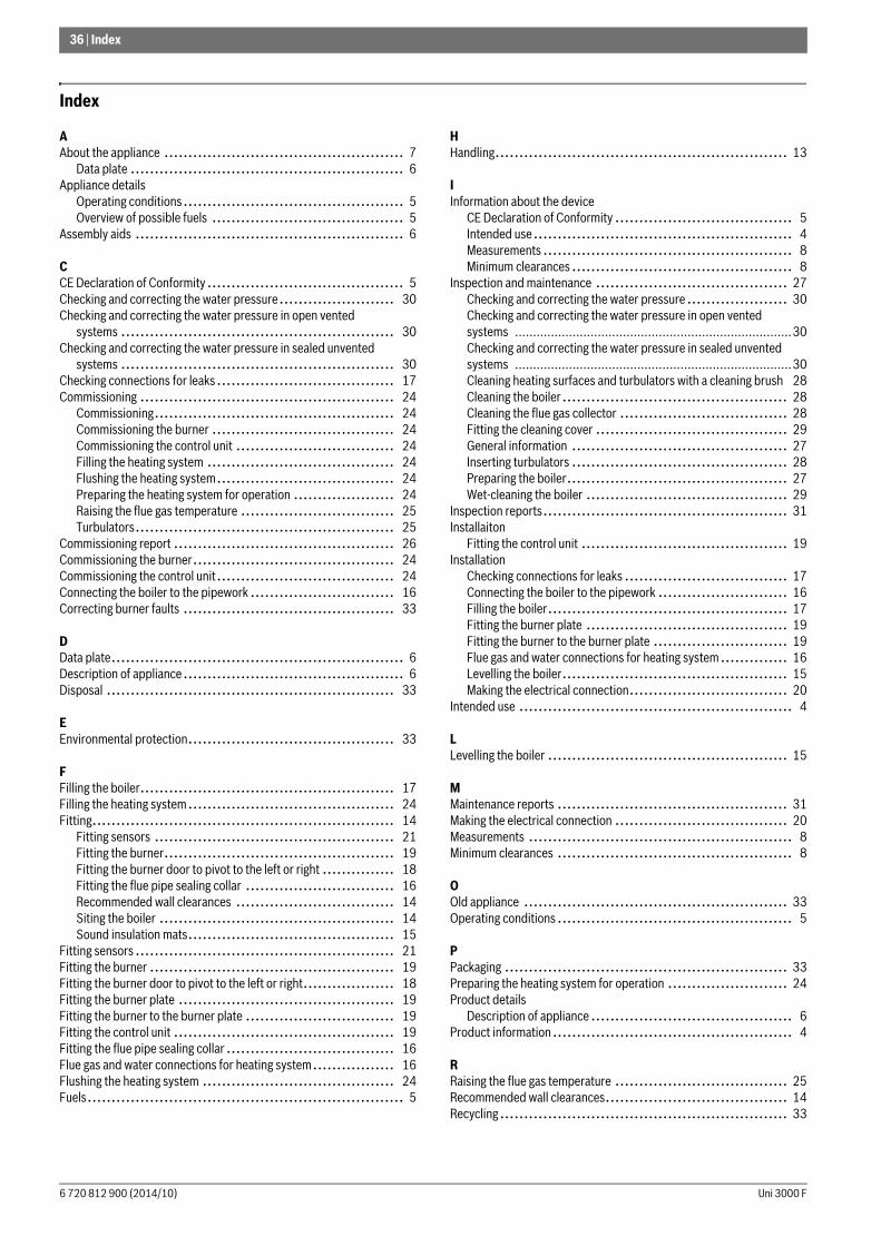
36 | Index
Index
AAbout the appliance .................................................. 7
Data plate ......................................................... 6Appliance details
Operating conditions.............................................. 5Overview of possible fuels ........................................ 5
Assembly aids ........................................................ 6
CCE Declaration of Conformity ......................................... 5Checking and correcting the water pressure........................ 30Checking and correcting the water pressure in open vented
systems ......................................................... 30Checking and correcting the water pressure in sealed unvented
systems ......................................................... 30Checking connections for leaks..................................... 17Commissioning ..................................................... 24
Commissioning.................................................. 24Commissioning the burner ...................................... 24Commissioning the control unit ................................. 24Filling the heating system ....................................... 24Flushing the heating system..................................... 24Preparing the heating system for operation ..................... 24Raising the flue gas temperature ................................ 25Turbulators...................................................... 25
Commissioning report .............................................. 26Commissioning the burner.......................................... 24Commissioning the control unit..................................... 24Connecting the boiler to the pipework .............................. 16Correcting burner faults ............................................ 33
DData plate............................................................. 6Description of appliance.............................................. 6Disposal ............................................................ 33
EEnvironmental protection........................................... 33
FFilling the boiler..................................................... 17Filling the heating system........................................... 24Fitting............................................................... 14
Fitting sensors .................................................. 21Fitting the burner................................................ 19Fitting the burner door to pivot to the left or right ............... 18Fitting the flue pipe sealing collar ............................... 16Recommended wall clearances ................................. 14Siting the boiler ................................................. 14Sound insulation mats........................................... 15
Fitting sensors ...................................................... 21Fitting the burner ................................................... 19Fitting the burner door to pivot to the left or right................... 18Fitting the burner plate ............................................. 19Fitting the burner to the burner plate ............................... 19Fitting the control unit .............................................. 19Fitting the flue pipe sealing collar ................................... 16Flue gas and water connections for heating system................. 16Flushing the heating system ........................................ 24Fuels.................................................................. 5
HHandling............................................................. 13
IInformation about the device
CE Declaration of Conformity ..................................... 5Intended use...................................................... 4Measurements .................................................... 8Minimum clearances .............................................. 8
Inspection and maintenance ........................................ 27Checking and correcting the water pressure ..................... 30Checking and correcting the water pressure in open vented systems .............................................................................30Checking and correcting the water pressure in sealed unvented systems .............................................................................30Cleaning heating surfaces and turbulators with a cleaning brush 28Cleaning the boiler............................................... 28Cleaning the flue gas collector ................................... 28Fitting the cleaning cover ........................................ 29General information ............................................. 27Inserting turbulators ............................................. 28Preparing the boiler.............................................. 27Wet-cleaning the boiler .......................................... 29
Inspection reports................................................... 31Installaiton
Fitting the control unit ........................................... 19Installation
Checking connections for leaks .................................. 17Connecting the boiler to the pipework ........................... 16Filling the boiler.................................................. 17Fitting the burner plate .......................................... 19Fitting the burner to the burner plate ............................ 19Flue gas and water connections for heating system .............. 16Levelling the boiler............................................... 15Making the electrical connection................................. 20
Intended use ......................................................... 4
LLevelling the boiler .................................................. 15
MMaintenance reports ................................................ 31Making the electrical connection .................................... 20Measurements ....................................................... 8Minimum clearances ................................................. 8
OOld appliance ....................................................... 33Operating conditions ................................................. 5
PPackaging ........................................................... 33Preparing the heating system for operation ......................... 24Product details
Description of appliance .......................................... 6Product information.................................................. 4
RRaising the flue gas temperature .................................... 25Recommended wall clearances...................................... 14Recycling............................................................ 33
Uni 3000 F6 720 812 900 (2014/10)

Index | 37
SSafety instructions ................................................... 3Shutdown
Shutting down the heating system............................... 27Shutting down the heating system in emergencies .............. 27
Shutting down....................................................... 27Shutting down the heating system .................................. 27Shutting down the heating system in emergencies .................. 27Siting the boiler ..................................................... 14Sound insulation mats............................................... 15Standard delivery .................................................... 7
TTechnical data
Uni 3000F .................................................. 11–12Tools ................................................................. 6Transport
Lifting with a crane .............................................. 14Moving the boiler with a forklift truck ............................ 13Moving the boiler with two pallet trucks ......................... 13
Turbulators.......................................................... 25Type overview........................................................ 5
6 720 812 900 (2014/10)Uni 3000 F

38 |
Notes
Uni 3000 F6 720 812 900 (2014/10)

| 39
Notes
6 720 812 900 (2014/10)Uni 3000 F