Outline Template (Microsoft Word)edge.rit.edu/content/P13361/public/BuildTest/Assembl… · Web...
29
HARDWARE ASSEMBLY MANUAL P13361: System Dynamics Filtering Laboratory Release Date: January 25, 2013 Revision: - PURPOSE The purpose of this document is to outline the procedures to be used in order to properly assemble the printed circuit board (PCB) and hardware module portion of the System Dynamics Filtering Laboratory. TABLE OF CONTENTS PURPOSE........................................................................ 1 TABLE OF CONTENTS.............................................................. 1 ENGINEERING SPECIFICATIONS, REV B..............................................1 MASTER LIST OF TEST EQUIPMENT..................................................2 TESTS.......................................................................... 3 TEST 1: PERFORM ACTIVITY.........................................................3 TEST 2: DESIGN POSSIBILITY/OUTCOME................................................5 TEST 3: STORAGE SIZE............................................................7 TEST 4: MINOR MAINTENANCE........................................................8 TEST 5: MAJOR REPAIR...........................................................10 TEST 6: AUDIO LEVEL............................................................12 APPENDIX...................................................................... 13 TABLE OF FIGURES No table of figures entries found.
Transcript of Outline Template (Microsoft Word)edge.rit.edu/content/P13361/public/BuildTest/Assembl… · Web...

HARDWARE ASSEMBLY MANUALP13361: System Dynamics Filtering Laboratory
Release Date: January 25, 2013 Revision: -
PURPOSE
The purpose of this document is to outline the procedures to be used in order to properly assemble the printed circuit board (PCB) and hardware module portion of the System Dynamics Filtering Laboratory.
TABLE OF CONTENTS
PURPOSE................................................................................................................................................................... 1
TABLE OF CONTENTS................................................................................................................................................. 1
ENGINEERING SPECIFICATIONS, REV B....................................................................................................................... 1
MASTER LIST OF TEST EQUIPMENT............................................................................................................................. 2
TESTS........................................................................................................................................................................ 3
TEST 1: PERFORM ACTIVITY..................................................................................................................................................3
TEST 2: DESIGN POSSIBILITY/OUTCOME..................................................................................................................................5
TEST 3: STORAGE SIZE.........................................................................................................................................................7
TEST 4: MINOR MAINTENANCE.............................................................................................................................................8
TEST 5: MAJOR REPAIR......................................................................................................................................................10
TEST 6: AUDIO LEVEL.........................................................................................................................................................12
APPENDIX................................................................................................................................................................ 13
TABLE OF FIGURES
No table of figures entries found.

Hardware Assembly Manual P13361
MASTER LIST OF PRODUCT COMPONENTS
The following is a master list of product components used to assemble the printed circuit board (PCB) and hardware module. See the Bill of Materials for more information.
January 25, 2013 2 Rev –

Hardware Assembly Manual P13361
P/N ID Qty Part Name Description
A3B 1 FILTER PCB ASSY Printed circuit board with all attached componenets
A301 1 BREADBOARD
A302 16 STAND_OFF PCB stand off, 1.5" long, 4-40 threaded, aluminum
A303 1 FILTER_MODULE_ENCLOSURE
A305 1 MOUNTING_PLATE
A306 30 STAND_OFF_SCREW Screws for standoffs 4-40 X 1/2"
A307 4 MOUNTING_PLATE_SCREW
A308 2 IC_LM741_AUDIO_AMPLIFIER
A3A01 1 JACK_BANANA_F_WHT
A3A02 1 JACK_BANANA_F_YLW
A3A03 2 JACK_BANANA_F_BLK
A3A04 2 JACK_BANANA_F_RED
A3A05 1 HEADPHONES
A3A06 2 ADAPTER_BANANA_M_BNC_F
A3A07 1 CNCTR_BANANA_MM_WHT
A3A08 1 CNCTR_BANANA_MM_YLW
A3A09 1 CNCTR_LINE_IN_3.5mm
A3A10 1 CNCTR_BREADBOARD_PWR
A3A11 1 CNCTR_BREADBOARD_GND
A3A12 1 CNCTR_BREADBOARD_OUT
A3A13 2 JACK_3.5mm_FEMALE Female mono headphone jack, 3.5mm,
A3A14 1 INTERFACE_PANEL
A3A15 1 RUBBER_SUPPORT
A3A17 1 VOICE_REC_BOARD
A3B01 1 PCB_BLANK
A3B02 4 CAPACITOR_1uF CAP ALUM 1UF 50V 20% RADIAL
Breadboard, 1 terminal strip, 2 bus strips, 270 contacts, 3.3" x 1.8", screw fastened
Filter module activitiy enclosure, ABS plastic, hinged lid with padlock option, 7.87"X5.9"X3.93"Plexi-glass plate used to mount hardware in enclosure
Screws for mounting plate to enclosure fastening 8-32 X 1/2"Integrated Circuit LM741 through hole, 8 pin, audio amplifier, used in breadboardFemale banana jack, surface mount, white (for reference PS connection)Female banana jack, surface mount, yellow (for +9V PS connection)Female banana jack, surface mount, black (for Ground)Female banana jack, surface mount, red (for FCN/DAQ connection)Headphones to be included with hardware, connect to line out jackAdapter male pos/gnd banana to male BNC (oscilloscope)Male banana to male banana patch cord, 24", white (for ground PS connection)Male banana to male banana patch cord, 24", yellow (for +9V PS connection)Mono 2' 3.5mm phone plugs (male-male), for connection between audio player and line in/mic jackPower / voltage in connection to breadboard from PCB, red, 22AWG, 100' (<1' needed)Ground connection to breadboard from PCB, black, 22AWG, 100' (<1' needed)Output voltage connection to PCB from breadboard, green 22AWG, 100' (<1' needed)
Plexi-glass plate used for input/output jack support, 4"X1.7"X.125" used, comes in 6"X12"Rubber sheet squares used to support Voice Recording Board, comes in 1/2" X 1/8" X 36" barsSeparated PCB that contains the voice recorder circuit and various attachmentsPrinted circuit board (no attached components), 4" x 3.3"X0.062", 13.2 sq. inches
C1, C2, C3, C4
January 25, 2013 3 Rev –

Hardware Assembly Manual P13361
A3B04 3 CAPACITOR_100uF
A3B05 1 CAPACITOR_47nF
A3B06 3 CAPACITOR_100nF
A3B07 1 CAPACITOR_220uF
A3B08 4 DIODE_GP 1N4001 diode, general purpose
A3B09 1 LED_6.35mm_RED
A3B10 1 CONNECTION_HEADER Connector to PCB, JP1 JP2 filter select/out selectA3B11 1 RESISTOR_1kOHM Resistor, through hole, 1% tol., (1 kilo-Ohm)A3B13 R1, R6 2 RESISTOR_100 OHM Resistor, through hole, 5% tol., (100 Ohm)A3B14 1 RESISTOR_330 OHM Resistor, through hole, 5% tol., (330 Ohm)A3B15 2 RESISTOR_1.6kOHM Resistor, through hole, 5% tol., (1.6K -Ohm)A3B16 1 RESISTOR_ 3.16kOHM Resistor, through hole, 1% tol., ( 3.16K -Ohm)A3B17 1 RESISTOR_ 800OHM Resistor, through hole, 5% tol., (800-Ohm)A3B18 1 SWITCH_SPDT_SLIDER SPDT slider switch, surface mount
A3B20 1 IC_LM7805_VOLTAGE_REGULATOR
A3B21 2 TP_BLUE Test point, blueA3B22 2 TP_RED Test point, redA3B21 2 TP_BLACK Test point, blackA3B22 4 JUMPER Connecting Jumpers for A3B10
C5, C6, C7
Ceramic capacitor, through hole, 20% tol., (100micro-Farrad)Ceramic capacitor, through hole, 20% tol., (47 nano-Farrad)Ceramic capacitor, through hole, 5% tol., (100 nano-Farrad)Ceramic capacitor, through hole, 5% tol., (220 micro-Farrad)
Red LED panel indicator light, through hole, 635nm, 1.8V
Integrated Circuit, LM7805, through hole, 3 pin, voltage regulator
MASTER LIST OF ASSEMBLY EQUIPMENT
The following is a master list of equipment used to assemble the printed circuit board (PCB) and hardware module.
January 25, 2013 4 Rev –

Hardware Assembly Manual P13361
ID Qty Description Suggested Model1 1 Electronics laboratory studio classroom System Dynamics classroom (GLE-2120)
2 1 DC 12V Power Supply GW Instek Laboratory DC Power Supply (GPS-3303)
3 1 Oscilloscope
4 1 Any Electronics laboratory computer
5 2 BNC Female-Female Patch Cable Pamona 48" BNC F-F Patch Cable (4277-C-48)6 1 Soldering Iron Pace 120V PS-90 Soldering Iron (8007-0528)7 1 Lead Free Solder Multicore 28 Gauge Solder (796065)8 1 Needle Nose Pliers Stanley 5" Needle Nose Pliers (84-096)
9 1 Wire Cutters Craftsman Wire Cutter-Stripper and Crimper (76575)
10 1 Wire Strippers / Crimpers Craftsman Wire Cutter-Stripper and Crimper (76575)
11 1 Hex Screwdriver Craftsman 6-in-1 LED Screwdriver (35722)12 1 Slotted Screwdriver Craftsman 6-in-1 LED Screwdriver (35722)13 1 CA Glue Super Glue 2g (15109)
14 1 1/4" Rachet
15 1 7/16" Scocket
16 1 3/32" Socket
17 1 Utility Knife Craftsman Twin Blade Lockback Knife (#95013)
Agilent Technologies 60MHz Digital Storage Oscilloscope (DSO3062S)
Computer w/ Matlab, Labview, and attached DAQ
Craftsman 1/4 in Drive Quick Release Teardrop Rachet (#44807)Craftsman 9 pc. Universal 1/4 in Dr. Socket Set, Inch (#38209)Craftsman 9 pc. Universal 1/4 in Dr. Socket Set, Inch (#38209)
January 25, 2013 5 Rev –

Hardware Assembly Manual P13361
PRINTED CIRCUIT BOARD (PCB) ASSEMBLY
This section outlines how to assemble the custom printed circuit board (PCB).
PRODUCT COMPONENTS
P/N ID Qty Part Name Description
A3B01 1 PCB_BLANK
A3B02 4 CAPACITOR_1uF CAP ALUM 1UF 50V 20% RADIAL
A3B04 3 CAPACITOR_100uF
A3B05 1 CAPACITOR_47nF
A3B06 3 CAPACITOR_100nF
A3B07 1 CAPACITOR_220uF
A3B08 4 DIODE_GP 1N4001 diode, general purpose
A3B09 1 LED_6.35mm_RED
A3B10 1 CONNECTION_HEADER Connector to PCB, JP1 JP2 filter select/out selectA3B11 1 RESISTOR_1kOHM Resistor, through hole, 1% tol., (1 kilo-Ohm)A3B13 R1, R6 2 RESISTOR_100 OHM Resistor, through hole, 5% tol., (100 Ohm)A3B14 1 RESISTOR_330 OHM Resistor, through hole, 5% tol., (330 Ohm)A3B15 2 RESISTOR_1.6kOHM Resistor, through hole, 5% tol., (1.6K -Ohm)A3B16 1 RESISTOR_ 3.16kOHM Resistor, through hole, 1% tol., ( 3.16K -Ohm)A3B17 1 RESISTOR_ 800OHM Resistor, through hole, 5% tol., (800-Ohm)A3B18 1 SWITCH_SPDT_SLIDER SPDT slider switch, surface mount
A3B20 1 IC_LM7805_VOLTAGE_REGULATOR
A3B21 2 TP_BLUE Test point, blueA3B22 2 TP_RED Test point, redA3B21 2 TP_BLACK Test point, blackA3B22 4 JUMPER Connecting Jumpers for A3B10
Printed circuit board (no attached components), 4" x 3.3"X0.062", 13.2 sq. inches
C1, C2, C3, C4C5, C6, C7
Ceramic capacitor, through hole, 20% tol., (100micro-Farrad)Ceramic capacitor, through hole, 20% tol., (47 nano-Farrad)Ceramic capacitor, through hole, 5% tol., (100 nano-Farrad)Ceramic capacitor, through hole, 5% tol., (220 micro-Farrad)
Red LED panel indicator light, through hole, 635nm, 1.8V
Integrated Circuit, LM7805, through hole, 3 pin, voltage regulator
ASSEMBLY EQUIPMENT
January 25, 2013 6 Rev –

Hardware Assembly Manual P13361
# Qty Description Suggested Model1 1 Electronics laboratory studio classroom System Dynamics classroom (GLE-2120)
2 1 DC 12V Power Supply GW Instek Laboratory DC Power Supply (GPS-3303)
3 1 Oscilloscope
4 2 BNC Female-Female Patch Cable Pamona 48" BNC F-F Patch Cable (4277-C-48)5 1 Soldering Iron Pace 120V PS-90 Soldering Iron (8007-0528)6 1 Lead Free Solder Multicore 28 Gauge Solder (796065)7 1 Needle Nose Pliers Stanley 5" Needle Nose Pliers (84-096)8 1 Hex Screwdriver Craftsman 6-in-1 LED Screwdriver (35722)
Agilent Technologies 60MHz Digital Storage Oscilloscope (DSO3062S)
PROCEDURE
1. Here there will be the assembly procedure for the PCB with appropriate pictures
OPERATION TESTING
1. Board testing procedure that tells how to make sure the board works properly
DEBUGGING NOTES
Any debug notes about testing here
January 25, 2013 7 Rev –

Hardware Assembly Manual P13361
HARDWARE MODULE ASSEMBLY
This section outlines how to assemble the hardware module.
PRODUCT COMPONENTS
January 25, 2013 8 Rev –

Hardware Assembly Manual P13361
P/N ID Qty Part Name Description
A3B 1 FILTER PCB ASSY Printed circuit board with all attached componenets
A301 1 BREADBOARD
A302 15 STAND_OFF PCB stand off, 1.5" long, 4-40 threaded, aluminum
A303 1 FILTER_MODULE_ENCLOSURE
A305 1 MOUNTING_PLATE
A306 30 STAND_OFF_SCREW Screws for standoffs 4-40 X 1/2"
A307 4 MOUNTING_PLATE_SCREW
A308 2 IC_LM741_AUDIO_AMPLIFIER
A3A01 1 JACK_BANANA_F_WHT
A3A02 1 JACK_BANANA_F_YLW
A3A03 2 JACK_BANANA_F_BLK
A3A04 2 JACK_BANANA_F_RED
A3A05 1 HEADPHONES
A3A06 2 ADAPTER_BANANA_M_BNC_F
A3A07 1 CNCTR_BANANA_MM_WHT
A3A08 1 CNCTR_BANANA_MM_YLW
A3A09 1 CNCTR_LINE_IN_3.5mm
A3A10 1 CNCTR_BREADBOARD_PWR
A3A11 1 CNCTR_BREADBOARD_GND
A3A12 1 CNCTR_BREADBOARD_OUT
A3A13 2 JACK_3.5mm_FEMALE Female mono headphone jack, 3.5mm,
A3A14 1 INTERFACE_PANEL
A3A15 1 RUBBER_SUPPORT
A3A17 1 VOICE_REC_BOARD
Breadboard, 1 terminal strip, 2 bus strips, 270 contacts, 3.3" x 1.8", screw fastened
Filter module activitiy enclosure, ABS plastic, hinged lid with padlock option, 7.87"X5.9"X3.93"Plexi-glass plate used to mount hardware in enclosure
Screws for mounting plate to enclosure fastening 8-32 X 1/2"Integrated Circuit LM741 through hole, 8 pin, audio amplifier, used also for built in active filtersFemale banana jack, surface mount, white (for reference PS connection)Female banana jack, surface mount, yellow (for +9V PS connection)Female banana jack, surface mount, black (for Ground)Female banana jack, surface mount, red (for FCN/DAQ connection)Headphones to be included with hardware, connect to line out jackAdapter male pos/gnd banana to male BNC (oscilloscope)Male banana to male banana patch cord, 24", white (for ground PS connection)Male banana to male banana patch cord, 24", yellow (for +9V PS connection)Mono 2' 3.5mm phone plugs (male-male), for connection between audio player and line in/mic jackPower / voltage in connection to breadboard from PCB, red, 22AWG, 100' (<1' needed)Ground connection to breadboard from PCB, black, 22AWG, 100' (<1' needed)Output voltage connection to PCB from breadboard, green 22AWG, 100' (<1' needed)
Plexi-glass plate used for input/output jack support, 4"X1.7"X.125" used, comes in 6"X12"Rubber sheet squares used to support Voice Recording Board, comes in 1/2" X 1/8" X 36" barsSeparated PCB that contains the voice recorder circuit and various attachments
ASSEMBLY EQUIPMENT
January 25, 2013 9 Rev –
Hardware Assembly Manual P13361
# Qty Description Suggested Model1 1 Electronics laboratory studio classroom System Dynamics classroom (GLE-2120)
2 1 DC 12V Power Supply GW Instek Laboratory DC Power Supply (GPS-3303)
3 1 Oscilloscope
5 2 BNC Female-Female Patch Cable Pamona 48" BNC F-F Patch Cable (4277-C-48)6 1 Soldering Iron Pace 120V PS-90 Soldering Iron (8007-0528)7 1 Lead Free Solder Multicore 28 Gauge Solder (796065)8 1 Needle Nose Pliers Stanley 5" Needle Nose Pliers (84-096)
9 1 Wire Cutters Craftsman Wire Cutter-Stripper and Crimper (76575)
10 1 Wire Strippers / Crimpers Craftsman Wire Cutter-Stripper and Crimper (76575)
11 1 Hex Screwdriver Craftsman 6-in-1 LED Screwdriver (35722)12 1 Slotted Screwdriver Craftsman 6-in-1 LED Screwdriver (35722)13 1 CA Glue Super Glue 2g (15109)
14 1 1/4" Rachet
15 1 7/16" Scocket
16 1 3/32" Socket
17 1 Utility Knife Craftsman Twin Blade Lockback Knife (#95013)
Agilent Technologies 60MHz Digital Storage Oscilloscope (DSO3062S)
Craftsman 1/4 in Drive Quick Release Teardrop Rachet (#44807)Craftsman 9 pc. Universal 1/4 in Dr. Socket Set, Inch (#38209)Craftsman 9 pc. Universal 1/4 in Dr. Socket Set, Inch (#38209)
PROCEDURE
INTERFACE PANEL
1. Use the utility blade (ID 16) to cut sections of rubber (A3A15) to cover the bottom of the voice recorder board (A3A17)
2. Once the rubber is cut, use the CA glue (ID 13) to glue it to the voice recorder board (See Figure 1)
Figure 1: Rubber Backing on Voice Recorder Board
January 25, 2013 10 Rev –

Hardware Assembly Manual P13361
3.
4. Per Figure 2 below, thread the yellow (A3A02), white (A3A01), red x 2 (A3A04), and black x 2 (A3A03) banana jacks, and the mono audio jacks (A3A13) into the blank interface panel (A3A14)
Figure 2: Jack Locations on Interface Panel
5. Use the ¼” rachet (ID 13) and the 7⁄16” socket (ID 14) to tighten down the banana jacks
6. Use the ¼” rachet (ID 13) and the 3⁄32” socket (ID 15) to tighten down the audio jacks
7.
OPERATION TESTING
8. Board testing procedure that tells how to make sure the board works properly
DEBUGGING NOTES
Any debug notes about testing here
9.
January 25, 2013 11 Rev –

Hardware Assembly Manual P13361
APPENDIX
ACTIVITY UNDERSTANDING QUIZ............................................................................................................................. 14
TEST DATA SHEETS................................................................................................................................................... 16
TEST 1: PERFORM ACTIVITY................................................................................................................................................16
TEST 2: DESIGN POSSIBILITY/OUTCOME................................................................................................................................17
TEST 3: STORAGE SIZE.......................................................................................................................................................19
TEST 4: MINOR MAINTENANCE...........................................................................................................................................20
TEST 5: MAJOR REPAIR......................................................................................................................................................21
TEST 6: AUDIO LEVEL.........................................................................................................................................................22
January 25, 2013 12 Rev –

Hardware Assembly Manual P13361
ACTIVITY UNDERSTANDING QUIZ
Name:_________________________ Date: ____/____/2013Grade: ⁄ 10
1.) Questions to be determined by the content of the laboratory activity manual. The questions are likely to span more than one line.a. Answer 1b. Answer 2c. Answer 3d. Answer 4e. Answer 5
2.) Questions to be determined by the content of the laboratory activity manual. The questions are likely to span more than one line.a. Answer 1b. Answer 2c. Answer 3d. Answer 4e. Answer 5
3.) Questions to be determined by the content of the laboratory activity manual. The questions are likely to span more than one line.a. Answer 1b. Answer 2c. Answer 3d. Answer 4e. Answer 5
4.) Questions to be determined by the content of the laboratory activity manual. The questions are likely to span more than one line.a. Answer 1b. Answer 2c. Answer 3d. Answer 4e. Answer 5
5.) Questions to be determined by the content of the laboratory activity manual. The questions are likely to span more than one line.a. Answer 1b. Answer 2c. Answer 3
January 25, 2013 13 Rev –

Hardware Assembly Manual P13361
d. Answer 4e. Answer 5
6.) Questions to be determined by the content of the laboratory activity manual. The questions are likely to span more than one line.a. Answer 1b. Answer 2c. Answer 3d. Answer 4e. Answer 5
7.) Questions to be determined by the content of the laboratory activity manual. The questions are likely to span more than one line.a. Answer 1b. Answer 2c. Answer 3d. Answer 4e. Answer 5
8.) Questions to be determined by the content of the laboratory activity manual. The questions are likely to span more than one line.a. Answer 1b. Answer 2c. Answer 3d. Answer 4e. Answer 5
9.) Questions to be determined by the content of the laboratory activity manual. The questions are likely to span more than one line.a. Answer 1b. Answer 2c. Answer 3d. Answer 4e. Answer 5
10.) Questions to be determined by the content of the laboratory activity manual. The questions are likely to span more than one line.a. Answer 1b. Answer 2c. Answer 3
January 25, 2013 14 Rev –

Hardware Assembly Manual P13361
d. Answer 4e. Answer 5
January 25, 2013 15 Rev –

Hardware Assembly Manual P13361
TEST DATA SHEETTest 1: Perform Activity
Supervising Engineer: ____________________________________________________
Date Performed: ________________________________________________________
Test Equipment Checklist:
# Qty Description Acquired? Utilized Model
1 1 Electronics laboratory studio classroom
2 1 DC 12V Power Supply
3 1 Oscilloscope
4 1 Computer w/ Matlab, Labview, and attached DAQ
5 2 BNC Female-Female Patch Cable
6 2 Stopwatch
7 1 System Dynamics Instructor
8 2 ME Student
9 1 Activity Understanding Quiz
Test Documentation:
Student Laboratory Time Hands-On TimeHands-On Percentage % = (H.O. Time /
Total Time)
Test Notes:
January 25, 2013 16 Rev –
Hardware Assembly Manual P13361
Pass / Fail? _________________________________________________________________
Engineer Signature: ____________________________________ Date: ______________
TEST DATA SHEETTest 2: Design Possibility/Outcome
Supervising Engineer: ____________________________________________________
Date Performed: ________________________________________________________
Test Equipment Checklist:
# Qty Description Acquired? Utilized Model
1 1 Electronics laboratory studio classroom
2 1 DC 12V Power Supply
3 1 Oscilloscope
4 1 Computer w/ Matlab, Labview, and attached DAQ
5 2 BNC Female-Female Patch Cable
Test Documentation:
See following page
Test Notes:
January 25, 2013 17 Rev –

Hardware Assembly Manual P13361
Pass / Fail? _________________________________________________________________
Engineer Signature: ____________________________________ Date: ______________
Test Documentation:
January 25, 2013 18 Rev –
Hardware Assembly Manual P13361
# #
1 6
2 7
3 8
4 9
5 10
Implementation Method
(H/W or S/W)Filter Description / Wiring Schematic (include
component details)Implementation Method
(H/W or S/W)Filter Description / Wiring Schematic (include
component details)
January 25, 2013 19 Rev –

Hardware Assembly Manual P13361
TEST DATA SHEETTest 3: Storage Size
Supervising Engineer: ____________________________________________________
Date Performed: ________________________________________________________
Test Equipment Checklist:
# Qty Description Acquired? Utilized Model
1 1 Tape Measure
Test Documentation:
Hardware Kit DimensionsLegnth Width Height
Test Notes:
January 25, 2013 20 Rev –

Hardware Assembly Manual P13361
Pass / Fail? _________________________________________________________________
Engineer Signature: ____________________________________ Date: ______________
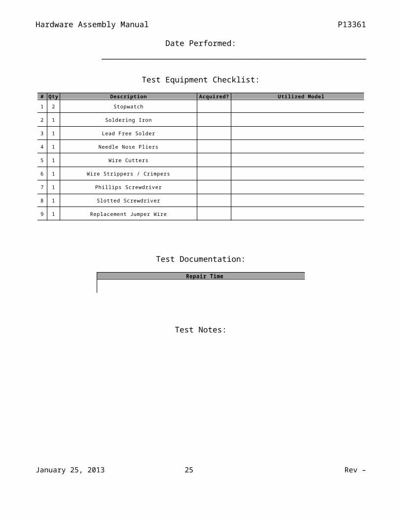
TEST DATA SHEETTest 4: Minor Maintenance
Supervising Engineer: ____________________________________________________
Date Performed: ________________________________________________________
Test Equipment Checklist:
January 25, 2013 21 Rev –

Hardware Assembly Manual P13361
# Qty Description Acquired? Utilized Model
1 2 Stopwatch
2 1 Soldering Iron
3 1 Lead Free Solder
4 1 Needle Nose Pliers
5 1 Wire Cutters
6 1 Wire Strippers / Crimpers
7 1 Phillips Screwdriver
8 1 Slotted Screwdriver
9 1 Replacement Jumper Wire
Test Documentation:
Repair Time
Test Notes:
Pass / Fail? _________________________________________________________________
Engineer Signature: ____________________________________ Date: ______________
TEST DATA SHEETJanuary 25, 2013 22 Rev –

Hardware Assembly Manual P13361
Test 5: Major Repair
Supervising Engineer: ____________________________________________________
Date Performed: ________________________________________________________
Test Equipment Checklist:
# Qty Description Acquired? Utilized Model
1 2 Stopwatch
2 1 Phillips Screwdriver
3 1 Soldering Iron
4 1 Lead Free Solder
5 1 Slotted Screwdriver
6 1 Replacement Assembled PCB
Test Documentation:
PCB Assembly Time Replacement Time
Test Notes:
January 25, 2013 23 Rev –

Hardware Assembly Manual P13361
Pass / Fail? _________________________________________________________________
Engineer Signature: ____________________________________ Date: ______________
TEST DATA SHEETTest 6: Audio Level
Supervising Engineer: ____________________________________________________
Date Performed: ________________________________________________________
Test Equipment Checklist:
# Qty Description Acquired? Utilized Model
1 1 Electronics laboratory studio classroom
2 1 DC 12V Power Supply
3 1 Tape Measure
4 6 Speaker
5 1 Decibel Meter
Test Documentation:
Trial Decibel Rating
1
2
3
January 25, 2013 24 Rev –
Hardware Assembly Manual P13361
Test Notes:
Pass / Fail? _________________________________________________________________
Engineer Signature: ____________________________________ Date: ______________
January 25, 2013 25 Rev –