Outline
43
description
Outline. CH.1 Introduction. This tower “ Nablus Commercial Forum “ has an area of 1800m 2 of basement . 23 floors and 1 basement garages surrounded by basement wall . Uses of floors are many: Parking, Offices, Services and Halls. There heights are 4.1 and 4.6 m. - PowerPoint PPT Presentation
Transcript of Outline


Outline
CH1.Introduction CH2.Preliminary Design CH3.3D Model

Page 3
CH.1 IntroductionThis tower “ Nablus Commercial Forum “ has an area of 1800m2 of basement.
23 floors and 1 basement garages surrounded by basement wall .
Uses of floors are many: Parking, Offices, Services and Halls.
There heights are 4.1 and 4.6 m.

Page 4
CH1. Design Data
The following codes and standardS will be used :
ACI 318-08 .UBC 97.IBC2009 .

Page 5
CH1 Design Data
Structural materialThe compressive strengths of concrete are : f’c = 28 Mpa for slabs and beams.f’c = 44 Mpa for mat foundation , Columns and shear walls .
Yield strength of Steel :fy = 420 Mpa .

Page 6
CH1 Design Data
Nonstructural materials :These materials include bricks, masonry stones, tiles and fill material.
Table below shows the unit weight of some materials :
Table 1.1, Nonstructural material density Material Density (KN/m3)Reinforced concrete 25Blocks 12Masonry 26Tiles 25Mortar 23Plastering 23Selected Filler (compacted base coarse ) 19Polycarbonate 0. 4

Page 7
CH1 Design Data
Loads:Gravity loads :
Table 1.2, heights, uses and loads
floor
Height Use Live load SDL
Basement 4.1 Garage 5 4Ground & 1-3 4.6 Retail Market 5 4
4-6 4.6 Stock market, Exchange hall
5 4
7-19 4.1 Offices 3 420-24 4.1 Restaurants 5 4

Page 8
Mechanical masonry: with 5.12 KN/mEscalators :Reactions of escalators R1, R2
R1=.67 h +3000 kg = 29.4 KNR2=.67 h +2300 kg = 22.6KN These reactions should be distributed to the beams that carrying the escalators .
CH1 Design Data

Page 9
Lateral load : Seismic loads : The structure is located in Nablus, which is classified as 2B according to Palestine seismic map .
Soil load:
CH1 Design Data
3

Page 10
CH1 Building Structural Design
Using two way solid slab that is A concrete slab supported by beams along all four edges and reinforced with steel bars arranged perpendicularly .

Page 11
CH.2 Preliminary Design
Fig. 2.1 , grid and column distribution

Page 12
CH.2 Preliminary Design
Fig.2.2, columns and beams name

Page 13
CH.2 Preliminary Design
The principal purposes for preliminary design of any structure are: (1)To obtain quantities of materials for making estimates of cost.
(2) Obtain a clear picture of the structural action,
(3) Establish the dimensions of the structure, and,
(4) Use the preliminary design as a check on the final design.

Page 14
CH.2 Preliminary Design
The principal purposes for preliminary design of any structure are: (1)To obtain quantities of materials for making estimates of cost.
(2) Obtain a clear picture of the structural action,
(3) Establish the dimensions of the structure, and,
(4) Use the preliminary design as a check on the final design.

Page 15
CH2 Design of Slab
Using Direct Design Method (DDM)Thickness of the slab: h min = fy = 420 Mpa, Ln = 9.4 - .8 = 8.6 m = So, h min = 0.21 m, we use 23 cm.

Page 16
CH2 Design of Beams
Maximum Length of the span in the project = 9.9 m. Min. depth of beams = ACI 318 - Table 9.5(a)
So, min. depth = = 0.53 m , use 600 X600 mm .

Page 17
CH2 Design of Frame
The following figures will display the analysis of Frame in y-direction .
Fig.2.4, Frame in Y – direction

Page 18
Fig 2.5 C.S & M.S
CH2 Design of Frame

Page 19
CH2 Design of Frame

Page 20
CH2 Design of Frame

Page 21
CH2 Design of Column
The preliminary columns dimensions can be estimated using the principle of tributary area.
ϕPn.max = 0.8ϕ[0.85fc (Ag – A st) +fy A st ]

Page 22
the following figure shows sample of column is to be design using tributary area .
Fig. 2.3, position of column 40
CH2 Design of Column

Page 23
G2-Column 40: First Floor =((9.15х3.095) х (.23 х 25+4))+(9.15+3.095) х 0.47 х 0.6 х 25+0.55
х 0.55 х 25 х 4.1) х 1.2+5 х (9.15 х 3.095) х 1.6=698.7KN. Floors 2,3 =(((9.15 х 3.095) х (.23 х 25+4))+(9.15+3.095) х 0.47 х 0.6 х 25+0.55
х 0.55 х 25 х 4.6) х 1.2+5 х (9.15 х 3.095) х 1.6=703.2KN. Floors 4,5 =(((9.15 х 4.295) х (.23 х 25+4))+(9.15+4.259) х 0.47 х 0.6 х 25+0.55
х 0.55 х 25 х 4.6) х 1.2+5 х (9.15 х 4.259) х 1.6=926.7KN. G2 =698.7+703.2X2+926.7X2=3958.5 KN.
CH2 Design of Column

Page 24
Group Name
Sub-Group
Max. Load Dimensions Columns
G1 1501 500*500 36,27,19,10,3,4
G2 3959 500*500 5,28,29,37,38,39,,40,41,42,43,35,26,18,9,2
G3
11,30,31,20G3-1 7613.52 600*600G3-2 1380 500*500
G4
32,33,34,25,17,8,13,14,6,7,1G4-1 13854.7 800*800G4-2 7838.4 700*700G4-3 6083 600*600G4-4 2255 500*500
G5
21,22,24
G5-1 22991.6 1000*1000
G5-2 14685.2 900*900G5-3 11356 800*800G5-4 7291 700*700G5-5 3226 600*600
G6
15,16,12,23
G6-1 36526.8 1300*1300
G6-2 28326.9 1200*1200
G6-3 25038.3 1100*1100
G6-4 16575.9 1000*1000G6-5 8114 900*900
CH2 Design of ColumnTable 2.1 , Columns dimensions and groups

Page 25
CH.3 3D Model

Page 26
CH3 ModificationsColumn Beam Wall
Torsional Constant
0.7 0.35 0.35
I about 2 axis
0.7 0.35 0.35
I about 2 axis
0.7 0.35 0.35
Slab MatBending M11
Modifier 0.25 0.25
Bending M22 Modifier
0.25 0.25
Bending M21 Modifier
0.25 0.25

Page 27
CH3 Seismic LOAD
The UBC97 code seismic parameters are as follows :
- The seismic zone factor, z=0.2.- The soil is very dense soil and soft rock , so the soil type is Sd.
- The importance factor: I=1.25 - The ductility factor : R = 5.5 - The seismic coefficient Ca= 0.28. - The seismic coefficient Cv= 0. 40.

Page 28
CH3 Verification
Compatibility :
Fig 3.1, compatibility view

Page 29
Equilibrium : The results by hand calculation as follow :
Total live load = 84185.45 Live Load with 1.75%
Total dead load =233879.1 with 5% error
CH3 Verification

Page 30
Stress Strain Relationships :
If we compare the moment values for the previous figure with hand calculation moment for interior beam which equal to:
From SAP :
We have an error = 2.9% which is acceptable .
M= WuLn 2L28 = 19.7×6.192 ×728 = 373 KN.M
CH3 Verification

Page 31
Deflection : By taking an average of deflection on corners
of max. panel deflection at seven story and conduct it from deflection in the middle of panel , the figure below shows the deflection at panel .
CH3 Verification

Page 32
CH3 Verification
Fig 3.2, Max deflection on panel

Page 33
Base Shear : To design or check base shear the following equations shall be determined as follow :
The total design base shear needn’t exceed the following :
The total design base shear needn’t less than the following :
CH3 Verification

Page 34
The error in X- direction can be acceptable in this case , because the structure is not symmetric .
CH3 Verification

Page 35
CH3 Shear & Basement Walls
The thickness of shear wall change from 0.65 m for first 8 story to 0.55 from story 8-16 and 0,45 from story 16-24 .
The thickness of the basement wall is 30 cm .
The basement has additional lateral load from soil more than other walls.
Page 36
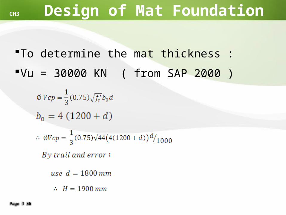
CH3 Design of Mat Foundation
To determine the mat thickness :Vu = 30000 KN ( from SAP 2000 )

Page 37
CH3 Design of Slab The figures below show the moment on the shell :
Fig 3.3, M11 { Min} Fig 3.4, M22 { Min}

Page 38
Fig 3.5 , M11 {max} Fig 3.6 , M22 {max}
CH3 Design of Slab

Page 39
Fig 3.7 , Reinforcement in x – direction
CH3 Design of Slab

Page 40
Fig 3.8 , Reinforcement in y – direction
CH3 Design of Slab

Page 41
Using SAP program to determine the reinforcement needed for a beam :
Fig . 3.9 flexure steel
Fig . 3.10 Torsion steel
CH3 Design of Beams
Page 42
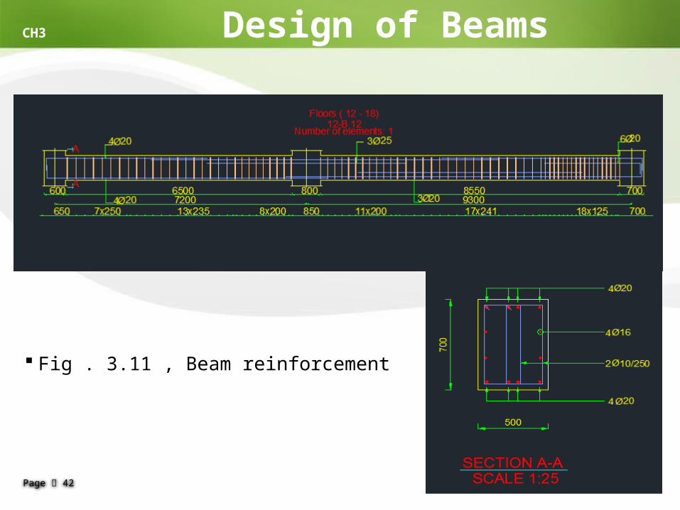
Fig . 3.11 , Beam reinforcement
CH3 Design of Beams

Page 43