OUTLET WORKS STILLING BASIN FOR TEXARKANA DAM …hydraulic-jump type stilling basin. Design capacity...
55
711'1' I (/fJ34 no .Jr '£0 CORPS OF ENGINEERS, U. S. ARM Y OUTLET WORKS STILLING BASIN FOR TEXARKANA DAM SULPHUR RIVER,TEXAS HYDRAULIC MODEL INVESTIGATION TECHNICAL MEMORANDU M NO. 2-346 WATERWAYS EXPERIMENT STATION ARI4Y· MRC MI S$. VICKS BURG, MISSISSIPPI JUNE 1952 PROPERTY o:F u. s. -- "i.Rttr--..... _ OF.FI OE CHIEF O•F ENG!IiNlEIIilllS LIBRARY
Transcript of OUTLET WORKS STILLING BASIN FOR TEXARKANA DAM …hydraulic-jump type stilling basin. Design capacity...

711'1' I (/fJ34 no.Jr 34~ '£0 CORPS OF ENGINEERS, U. S. ARMY
OUTLET WORKS STILLING BASIN FOR TEXARKANA DAM
SULPHUR RIVER,TEXAS
HYDRAULIC MODEL INVESTIGATION
TECHNICAL MEMORANDU M NO. 2-346
WATERWAYS EXPERIMENT STATION
ARI4Y· MRC YIC KSBUR~. MIS$.
VICKSBURG, MISSISSIPPI
JUNE 1952
PROPERTY o:F u. s.--"i.Rttr--....._ OF.FI OE CHIEF O•F ENG!IiNlEIIilllS LIBRARY

Report Documentation Page Form ApprovedOMB No. 0704-0188
Public reporting burden for the collection of information is estimated to average 1 hour per response, including the time for reviewing instructions, searching existing data sources, gathering andmaintaining the data needed, and completing and reviewing the collection of information Send comments regarding this burden estimate or any other aspect of this collection of information,including suggestions for reducing this burden, to Washington Headquarters Services, Directorate for Information Operations and Reports, 1215 Jefferson Davis Highway, Suite 1204, ArlingtonVA 22202-4302 Respondents should be aware that notwithstanding any other provision of law, no person shall be subject to a penalty for failing to comply with a collection of information if itdoes not display a currently valid OMB control number
1. REPORT DATE JUN 1952 2. REPORT TYPE
3. DATES COVERED 00-00-1952 to 00-00-1952
4. TITLE AND SUBTITLE Outlet Works Stilling Basin for Texarkana Dam, Sulphur River, Texas:Hydraulic Model Investigation
5a. CONTRACT NUMBER
5b. GRANT NUMBER
5c. PROGRAM ELEMENT NUMBER
6. AUTHOR(S) 5d. PROJECT NUMBER
5e. TASK NUMBER
5f. WORK UNIT NUMBER
7. PERFORMING ORGANIZATION NAME(S) AND ADDRESS(ES) U.S. Army Corps of Engineers,Waterway Experiment Station,3903 HallsFerry Road,Vicksburg,MS,39180
8. PERFORMING ORGANIZATIONREPORT NUMBER
9. SPONSORING/MONITORING AGENCY NAME(S) AND ADDRESS(ES) 10. SPONSOR/MONITOR’S ACRONYM(S)
11. SPONSOR/MONITOR’S REPORT NUMBER(S)
12. DISTRIBUTION/AVAILABILITY STATEMENT Approved for public release; distribution unlimited
13. SUPPLEMENTARY NOTES
14. ABSTRACT
15. SUBJECT TERMS
16. SECURITY CLASSIFICATION OF: 17. LIMITATION OF ABSTRACT Same as
Report (SAR)
18. NUMBEROF PAGES
54
19a. NAME OFRESPONSIBLE PERSON
a REPORT unclassified
b ABSTRACT unclassified
c THIS PAGE unclassified
Standard Form 298 (Rev. 8-98) Prescribed by ANSI Std Z39-18

<!llil'l<l!Cl<ll(:CJ~()II!l o!ilfll«l
Of;l(ll<!lfotl<OCll<tlllllCllllll<ll'll'l!l 'fl
FRONTISPIECE . Texarkana Dam Control Struct ures
PREFACE
Model investigations of the outlet works stilling basin for
Texarkana Dam were authorized by the Chief of Engineers in the third
indorsement to a letter to the Division Engineer, Lower Mississippi
Valley Division, dated 10 May 1949. The model studies were conducted
during the period May 1949-June 1950 in the Hydraulics Division of the
Waterways Experiment Station by Messrs. T. J. Buntin, John N. Strange,
and C. M. Wright, under the general supervision of Messrs. F. R. Brown
and T. E. Murphy.
Messrs. E. J. Williams, J. E. Sanders, C. L. Sumrall, Jr., and
i
F. B. Toffaleti, engineers of the Lower Mississippi Valley Division,
visited the Experiment Station at frequent intervals during the course
of the study to discuss testing procedures and to correlate test results
with design work being accomplished concurrently.
CONTENTS
PREFACE •
SUMMARY •
PART I: INTRODUCTION •
The Prototype • Purpose of Model Analysis •
PART II: THE MODEL •
Description • Scale Ratios
PART III: TESTS AND RESULTS
Original Design • Alterations to Original Design Recommended Design
PART IV: CONCLUSIONS AND RECOMMENDATIONS •
PHOTCGRAPHS 1-16
PlATES 1-14
iii
i
v
1
1 2
3
3 4
5
5 7
14
17

SUMMARY
The outlet works stilling basin for Texarkana Dam was studied on
a 1:25-scale model to insure adequacy of the basin in reducing the
velocity of flow issuing from the twin conduits.
v
Initial tests indicated the necessity for revision of various
stilling basin elements. Energy of flow from the conduits operating
singly, or in combination, was not diminished as the flow passed through
the stilling basin. Flow concentrated in areas adjacent to t11e splitter
wall and had upstream direction adjacent to the outside basin walls.
The desired performance of the stilling basin was secured by use
of warped transition sections downstream from the conduit exit portals,
elimination of the stepped apron, and reduction of 3 ft in the height
of the splitter wall. The elevation of the stilling basin and height
of end sill were not changed.

OUTLET iVORKS STILLING BASIN FOR TEXARKANA DAM
SULPHUR RIVER, TEXAS
Hydraulic Model Investigation
PART I : INTRODUCTION
The PrototYIJe
1. Texarkana Dam is an earth-fill
dam under construction on the Sulphur l .(.,_ ~ i~
River approximately 9 miles southwest of
Texarkana, Texas (fig. 1) . It will be
approximately 100 ft high and 18,500 ft
l ', I 0 .", . ...
long . The reservoir created by the dam
will have an area of 119,700 acres at
spillway crest elevation of 259 . 5* and
a total storage capacity of 2, 654, 300
acre-ft . The reservoir will extend
up the Sulphur River approximately
I
SCALE IN MlLES .. . .. e:::::c::JECJS
60
I.ITTLE ROCK~
1t~T0tt 0
MONROe'
40 miles . The reservoir will be Fig . 1 . Vicinity map
20, 300 acres in area and will store 145 , 300 acre-ft at the conservation
pool elevation of 220 .
2. Normal f lmv regulation will be accomplished by means of four
slide gates located within the intake structure of the outlet works .
Flow from the intake structure will pass through two circular conduits
* All elevations are in feet above mean sea level .

2
20 ft in diameter and approximately 480 ft in length, discharging into a
hydraulic-jump type stilling basin. Design capacity of the outlet works
is 281 000 cfs. Details of the stilling basin as originally designed and
as revised are shown on plates 1 and 9, respectively.
3. Flows exceeding the storage capacity of the reservoir will pass
over an uncontrolled chute-type spillway located in the right abutment of
the dam (see frontispiece). The spillway, with crest at elev 259.5, is
designed to pass a maximum discharge of 66,800 cfs under a head of 19.2
ft. High velocity flow will be reduced at the toe of the spillway by
means of a hydraulic-jump type stilling basin.
Purpose of Model Analysis
4. Previous experience has indicated that satisfactory stilling
basin performance is difficult to procure where symmetry of basin dimen
sions is not maintained about the center line of each conduit. The
general purpose of the model studies, therefore, was to examine the per
formance of the stilling basin of the outlet structures as originally
designed and to make such revisions as appeared necessary to effect
economies or improve flow conditions.

3
PART II: THE MODEL
Description
5. The model of Texarkana Dam outlet works was constructed to
an undistorted scale ratio of 1:25 (photograph 3) and reproduced approx
imately 400 ft of the conduits, the complete stilling basin and about
300 ft of the exit channel. 'I'he intake structure and upstream transi
tion section were not reproduced.
6. The stilling basin area was constructed of concrete and wood
to facilitate alterations. The twin conduits were fabricated of sheet
metal. ~fo metal gates with air vents were located at the upstream end
of the model conduits at the junction with the headbay of the model for
regulation of flow and simulation of prototype conditions.
7. The water used in the operation of the model was supplied by
a circulating system, the measurement of discharge being accomplished
by use of a venturi meter installed in the inflow line. Flow from the
supply line was discharged into the headbay where it was stilled by
baffles prior to its entrance into the conduits. The tailwater eleva
tion in the exit area was controlled by means of an adjustable tailgate.
After passing over the control tailgate the water flowed through a
return line back to the sump from which it was originally pumped.
8. Steel rails set to grade along each side of the model provided
a reference plane for use of all measuring devices. Average water
surface elevation was measured by means of a portable sounding rod
placed on an angle-beam supported by the rails. Velocities were
measured by means of a pitot tube arranged in a bracket to enable

4
measurements to be made for any direction of flow. Flow conditions were
recorded by means of photographs. The bed of the exit channel was molded
in sand for scour tests, and was capped with cement mortar for velocity
measurements. All scour tests were of one hour duration, model time.
Scale Ratios
9. The accepted equations of hydraulic similitude, based on the
Froudian relationships, were used to express the mathematical relation-
ships between the dimensions and hydraulic quantities of the model and
the prototype. General relationships for the transference of model data
to prototype equivalents, or vice versa, are presented in the following
table:
Dimension Ratio Scale Relationship
Length L:r 1:25
Area Ar = Lr-2 1:625
Velocity Vr = Lrl/2 1:5
Discharge Qr = Lr-5/2 1:3,125
Roughness Dr = lrl/6 1:1.710

5
PART III: TESTS AND RESULTS
10. It was necessary in all tests to adjust the disch~rge in
accordance with the computed pool-discharge relations furnished by repre-
sentatives of the Lower Mississippi Valley Division, since the intake
structure was not reproduced in the model, Discharge conditions for
'\vhich data were desired are tabulated below:
Discharge, cfs
5,000 10,000 10,000 10,000 10,000 14,000 15,000 18,000 28,000
Pool Elevation
259.5 259.5 242.5 222.2 259-5 259·5 259.5 259.5 259.5
Tailwater Elevation
203.95 210.0 210.0 210.0 212.3 212.3 212.45 213.1 214.7
Discharges of 10,000 and 18,000 cfs with their respect~ve pool and tail-
water conditions were considered most important for investigation. Dis-
charges in excess of 18,000 cfs lvill be infrequent, although the outlet
structures lvere designed for a maximum capacity of 28,000 cfs. A dis-
charge of 14,000 cfs with only one conduit in operation was most critical
for investigation of effect of splitter-wall elevation.
11. Test data are not presented for many of the alterations tried
in the model, because if an alteration obviously made no improvement in
flow conditions it was changed immediately without further investigation.
Original Design
12, Tests of the original design stilling basin (plate 1) indi-
cated unsatisfactory flow conditions for all discharges. Although flow

6
was symmetrical about the center line of the stilling basin, strong down-
stream currents existed along the splitter wall whereas currents along
the spray walls were upstream in direction (photographs 1 and 2) . Condi-
tions existing within each half of the stilling basin are also shown
diagrammatically in fig . 2 . The upstream currents along the spray walls
CONCENTRATED JET
~~~- -----~
CONFINING FORCES
Fig . 2. Flow in stilling basin of original design
actually helped confine the high velocity jets issuing from the conduits
against the splitter wall . Thus little or no reduction in velocity was
effected as flow passed through the stilling basin. The shaded portion
of the basin shm-rn in the figure cont ributed nothing toward improving
basin performance . The stepped portion of the apron appeared to have
little or no effect oo flow distribution wit hin the stilling basin.
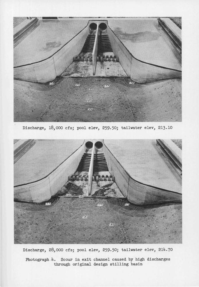
13. Prior to t he start of each scour test t he bed of the exit
channel was molded to elev 180. Scour caused ·by the flow conditions de-
picted in photographs 1 and 2 are shown on photographs 3 and 4. These
data indicate that the upstream flmv along the spray walls was of suffi-
cient magnitude to transport bed material from t he exit area into the

stilling basin, The lack of appreciable scour downstream from the end
sill is an indication that the high velocities were confined to surface
flow.
7
14. Velocities measured over the cross section of the basin at the
end sill indicate the extent and magnitude of the currents in the stilling
basin for various discharges (plates 2-3). Downstream flow was confined
to the center third of the stilling basin and varied in velocity from
about 5 ft per sec at the end sill to 13 ft per sec at the water surface
for a discharge of 18,000 cfs.
Alterations to Original Design
Baffle piers
15. Initial efforts to improve stilling basin performance involved
alterations to the height, shape, and location of baffle piers. Baffle
piers 4 and 8 ft in height and either stepped or vertical were investiga
ted. The baffle piers, for the most part, were located in rows perpendic
ular to the splitter wall; however, one test was conducted wherein the
baffle piers ivere slanted diagonally across the halves of the stilling
basin, i.e., the baffle pier adjacent to the splitter wall was farther
upstream than the baffle pier in the same row adjacent to the spray wall.
Elimination of all baffle piers to study the absolute effect of the piers
indicated that they were of some use in reducing the velocity of flow
passing through the stilling basin. Comparison of the scour data (photo
graph 5) obtained after removal of the baffle piers with the scour data
(photograph 3) obtained with the basin of original design indicates an
increase in scour resulting from elimination of the baffle piers. Tests

8
of other alterations to the baffle piers indicated no improvement in basin
performance over that obtained with the basin of original design. The
high velocity flow issuing from the conduits pushed the tailwater farther
downstream as tne baffle piers were reduced in height or were moved down
stream. Therefore it was decided to retain the original design of baffle
piers, although flow was still confined to the middle third of the
stilling basin.
Horizontal apron and end sill elevation
16. The horizontal apron and end sill were raised 5 ft to elevation
180 and 185, respectively, in an effort to improve flow distribution in
the stilling basin. The effect of this alteration on basin performance
was negligible, although velocities over the end sill were increased
(plate 4). However, the magnitude of velocities over the end sill was
less than that considered likely to cause erosion of the exit area. A
10-ft increase in the height of the end sill (top elevation 190) increased
velocities (plate 4) and was considered undesirable. Therefore, an ele
vation of 180 was tentatively adopted for the horizontal apron in conjunc
tion with a 5-ft-high end sill. Flmv- conditions were still about the
same as those observed in the stilling basin of original design. The
stilling basin was later returned to its original elevation to maintain
the end sill at the same elevation as the exit channel downstream.
Sloped apron
17. Alterations to the angle of the steps forming the sloping por
tion of the basin floor failed to improve flow conditions. Velocities at
the end sill, with the angle of flare of the steps with respect to the
spray walls increased from 90 to 120 degrees (fig. 3), are shown on plate 5.

9
~00,0'
,H£:.._08.0 ' - -f-1 ~11.0=1 1~
!) f'T Sll.l.
CLEV 17$. 0
---- ORIGINAt.. S'TtPS -- AEVI $EO STE~
Fig. 3. Stilling basin with i ncreased angle of flare of steps
Elimination of the steps ent i r ely by molding a smooth curve t o t he equa
tion of x2 = -270Y (f ig . 4) had no effect on f low conditions . Thus ,
eliminat ion of the st eps from the stil l i ng basin design appeared war-
rant ed. Although flovT conditions were not affected by such revision,
some economies i n construct i on could be made .
~--------~----------- 200'--------------------~ 1----<o'---f----JIIJ.S'---f-- ti.S' 6' IT' -fo-----W------>!f--IS'
Fig. 4. Sti lling basin with steps replaced by smooth curve
Stilling basin width
18. Efforts were directed towar d el imination of t he eddies adja-
cent t o the spray walls by decreasing the width of the basin, inas~uch as
neither alterations t o .t he baffle piers nor to the basin f loor effected

10
the desired improvement in flow conditions. Accordingly, the width of
the stilling basin at the end sill was decreased from 127 to 82.5 ft.
The resulting flow conditions (photograph 6) approached those desired.
Eddy action adjacent to the spray walls was almost eliminated and better
flow distribution within the basin resulted. Although velocities over
the end sill were increased only slightly for a discharge of 10,000 cfs,
velocities for a discharge of 18,000 cfs were considered excessive
(plate 6). Therefore efforts to secure the desired flow distribution by
reducing the width of the stilling basin were abandoned.
Deflector blocks at conduit exit portal
19. Efforts vrere made to direct the jets issuing from the conduits
away from the splitter wall, since alteration of the stilling basin proper
did not accomplish the desired results. The four types of deflector
blocks investigated are shown in fig. 5. Use of the deflector blocks ac
complished the desired flow distribution and stilling basin performance,
and appeared to give the desired results (see plate 7). However, it was
realized that the blocks -vrould be subject to damage by debris and that a
similar device to deflect the high velocity jet should be devised.
Revision of exit portal
20. Efforts to secure uniform flow distribution in the stilling
basin included constriction of the conduit exit portal and use of a
humped floor starting within the portal and extending into the stilling
basin. None of these efforts was successful. Design engineers of the
Lovrer Mississippi Valley Division were of the opinion that diversion of
the high velocity jets should be accomplished -vrithin the confines of the
stilling basin rather than I<Tithin the conduit proper.
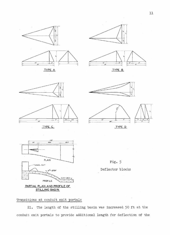
TYPE A
TYPE C
PARTIAL PLAN AND PROfiLE OF ST ILLING BASIN
Transit ions at conduit exit :portals
TYPE B
TYPE ·D
Fig. 5
Deflector blocks
21 . The lengt h of t he stilling basin was i ncreased 50 ft a t t he
11
conduit exit portals t o :provide additi onal l ength for deflection of the

12
high velocity jets. This increase in length of stilling basin was accom
plished by shortening the conduits 50 ft. The stilling basin apron and
end sill also were lowered to their original elevations of 175 and 180,
respectively, at the request of engineers of the Lower Mississippi Valley
Division. This was done to maintain the end sill at the same elevation
as the exit channel downstream. 'I'he use of broad-crested weirs 5 to 7. 5
ft in height and located about 50 ft downstream from the conduit exit por
tals was first investigated. Resulting flow conditions were considered
unsatisfactory (photograph 7). Impact of flow on the weirs was excessive
and the discharge capacity of the conduits was reduced. Wedge-shaped
fillets of varying slopes adjacent to the splitter wall (fig. 6) were next
Fig. 6. Wedge-shaped fillets adjacent to splitter vrall in stilling basin

13
investigated. Use of t hese fillets resul ted in a marked improvement
i n flow conditions (photograph 8) . A good hydraulic jump obtained and
flow appeared evenly distributed across the stilling basin (plate 8 ) .
Erosion test data for f l ows of 10,000 and 18,000 cfs are presented i n
photograph 9. A third scheme was investigated, despite the fact that the
desired flovr conditions had been obtained, vrhich involved a 5- ft superele-
vation of the apron floor immediately downstream from t he exit portal
(fig. 7 ). The radius of curvature of the spray vralls in the immediate
vicinity of the conduit exit portals also was increased from 100 to 575 ft .
SECTION SO' DOWNSTREAM OF TUNNEL EXIT
t:LEV 219.0 cu:v lf$.0
CL£V 2:0.(1
t=--=-=~---=.-. -----~
~('V/lS.O
ELEVATION A LONG FACE OF SPLITTER WALL
Fig . 7 . Apron floor superelevated 5 ft immediately downstream from port als
The resulting flow conditions (photograph 10) were similar t o those ob -
served vrit h the "'vedge- shaped fille t . A good hydraulic jump obtained and
flow appeared unifo:i:·mly di str ibuted. Since t he superelevated transition
results in a continuously submer ged deflec t ing surface, it is believed
superior to the wedge - shaped fillet for installation in the prototype

14
structure. Attempts to reduce the over-all length of the stilling basin
from 250 to 200 ft were unsuccessful.
Splitter wall
22. Tests were made of various alterations to the splitter wall in
an effort to effect economies in its construction. One test also was con
ducted with the splitter wall eliminated entirely. Elimination of the
splitter wall destroyed all evidence of jump action and a large amount of
scour in the exit area (photograph 11) resulted. Consequently, the
splitter wall was considered an important part of the stilling basin.
Alterations to the wall were investigated involving variation of the top
elevation of the downstream portion of the wall from 213 to 198, and
variation of the length of the wall. Tests of these alterations, with
both conduits in operation, indicated the possibility of reducing the top
elevation to 198 and shortening it to the second row of baffle piers.
However, representatives of the Lower Mississippi Valley Division requested
that the wall be designed to provide good stilling basin performance for a
discharge of 14,000 cfs through one conduit. It was decided, on the oasis
of general hydraulic behavior of flow within the stilling basin and the
maximum depth of scour noted in the exit area, that the lower end of the
splitter wall should be at elevation 210. It also was determined from
these data that the shortest length possible was 200 ft; thus, the wall
was terminated 50 ft upstream from the end sill.
Recommended Design
23. The stilling basin design encompassing all of the most satis
factory elements derived from studies of the alterations previously

15
described is shown in photograph 12 and plate 9. Comparison of the
physical features of the recommended design of stilling basin with those
of the original design (plate 1) indicates the following:
a, The over-all length of stilling basin was increased 50 ft by reducing the length of the conduits.
b. A warped transition vrith a 5-ft superelevation of the apron floor at the conduit exit portals was used to secure the desired flow distribution.
c. The radius of the curved spray walls near the exit portals was increased from 100 to 575 ft.
d, The stepped portion of the apron was replaced with a smooth trajectory curve •,
e. The downstream portion of the splitter wall was reduced 35 ft in length and the top lowered from elev 213 to 210.
24. Flmv conditions within the stilling basin of recommended
design v-rere excellent for both twin- and single-conduit operation (photo-
graphs 12-14). ·Hater-surface profiles showing the location of the ·
hydraulic jump in each half of the stilling basin for the most important
discharges are shown on plate 10. Results of erosion tests for the same
discharges are shown in photographs 15 and 16. Comparison of these
scour data with those obtained downstream from the stilling basin of
original design (photographs 3 and 4) indicates considerable improve-
ment. Velocity data measured over the cross section of the channel at
the end sill are shown on plates 11 and 12. These data indicate uniform
flow conditions across the channel. The maximum velocity recorded over
the end sill for both conduits in operation was less than 4 ft per sec
for all discharges. For conditions of one conduit operating (plate 11)
the maximum velocity over the end sill was 7.6 ft per sec for a discharge
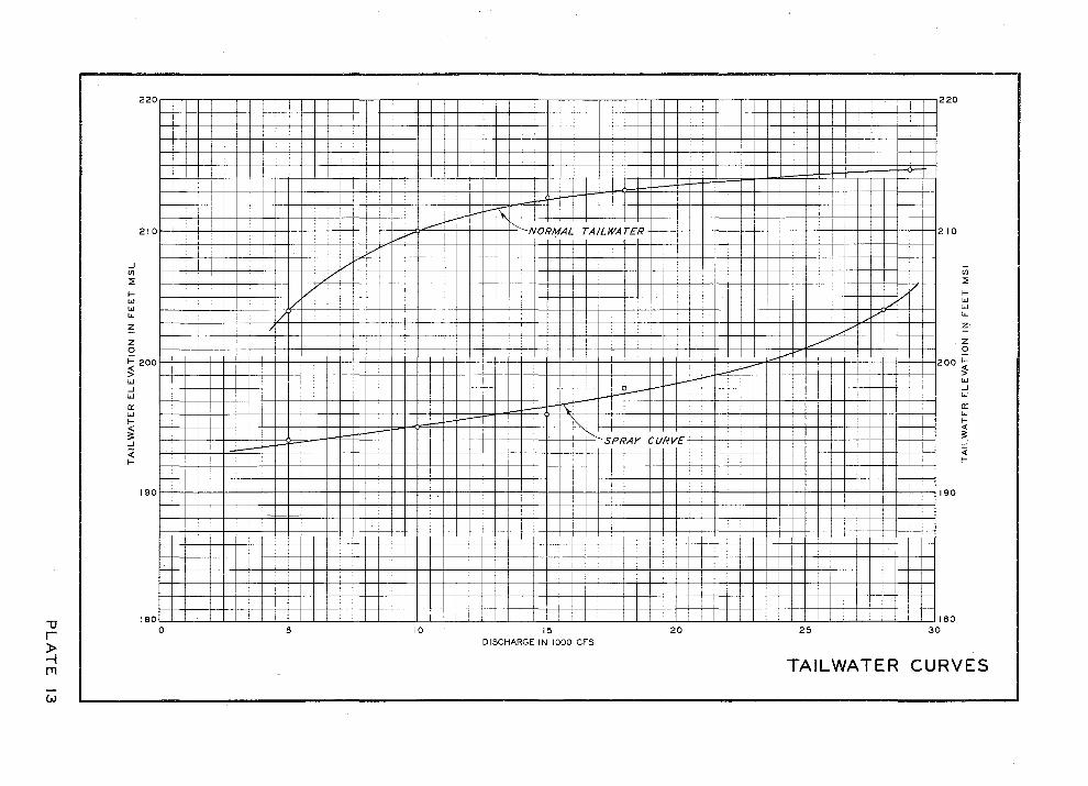
of 14,000 cfs. The tailwater elevation could be lowered 15 ft for

16
discharges of 10,000 and 18,000 cfs before spray action occurred (plate
13); at the maximum discharge of 28,000 cfs the tailwater could be
lowered 10 ft before spray occurred. variation in tailwater revealed
that minimum end-sill velocities occurred at normal tailwater depth for
a discharge of 10,000 cfs (plate 14). Minimum velocity occurred at a
tailwater depth about 6 ft below normal for a discharge of 18,000 cfs.

17
PART IV: CONCLUSIONS A11]) RECOMMENDATIONS
25. Model investigations permitted the development of a satisfac-
tory design for all conditions of discharge and conduit operation. The
most important aspect of the problem of securing good flow distribution
in each half of the stilling basin was the development of a transition
at the conduit exit portals. This transition involved the supereleva-
tion of the floor 5 ft to divert flow away from the splitter wall. It
was necessary to increase the over-all length of the stilling basin 50
ft, inasmuch as it was desired to place the transition entirely outside
the conduits rather than make it a part of the exit portal. The increase
in length of the stilling basin was accomplished by shortening the con-
duits. Details of the stilling basin design recommended for construe-
' tion in the prototype are shown on plate 9.
26. Flow conditions with the recommended stilling basin design
were excellent for all conditions of discharge and conduit operation.
Also a considerable reduction in tailwater, belo>v that computed, could
occur without decreasing the effectiveness of the stilling basin.

PHOTOGRAPHS

Discharge, 5,000 cfs; pool elev, 259-50; tailwater elev, 203.95
Discharge, 10,000 cfs; pool elev, 259-50; tailwater elev, 210. 00
Photograph 1. Flow in original design stilling basin was downstream in direction along splitter wall and upstream along spray walls
at low discharges

Discharge, 18,000 cfs; pool elev, 259-50; tailwater elev, 213.10
Discharge, 28,000 cfs; pool elev, 259-50; tailwater elev, 214.70
Photograph 2. Flow in original design stilling basin remained downstream in direction along splitter wall and upstream along spray walls
at high discharges

Discharge, 5,000 cfs; pool elev, 259-50; tailwater elev, 203.95
Discharge, 10,000 cfs; pool elev, 259-50; tailwater elev, 210.00
Photograph 3. Scour in exit channel caused by low discharges through original design stilling basin
Discharge, 18,000 cfs; pool elev, 259.50; tailwater elev, 213.10
Discharge, 28,000 cfs; pool elev, 259.50; tailwater elev, 214.70
Photograph .4. Scour in exit channel caused by high discharges through orjginal design stilling basin

:•u>tw ~·• ?J1ll1 ·~
'.t'.:\loll(,{. ( ·:.O::li llU'''·":t.r!Jn
~ )'.Q,.art • -l~~ .....
Discharge, 10,000 cfs; pool elev, 259.50; tailwater elev, 210.00
Photograph 5· Scour in exit channel caused by low discharges through original design stilling basin with
baffle piers removed

Discharge, 10,000 cfs; pool elev, 259-50; tailwater elev, 210.00
Discharge, 18,000 cfs; pool elev, ~59-50; tailwater elev, 213.10
Photograph 6. Flow conditions with basin width at end sill decreased by 44.5 ft

Discharge, 10,000 cfs; pool elev, 259.50; tailwater elev, 210.00
Discharge, 18,000 cfs; pool elev, 259 . 50; tailvater elev, 213.10
Photograph 7. Flow conditions with broad-crested weirs installed in stilling basin

Discharge, 10,000 cfs; pool elev, 242.50; tailwater elev, 210.00
Discharge, 18,000 cfs; pool elev, 259.50; tailwater elev, 213.10
Photograph 8. Flow conditions with wedge- shaped fillet placed adjacent to splitter wall

Discharge, 10,000 cfs; pool elev, 259-50; tailwater elev, 210.00
Discharge, 18,000 cfs; pool elev, 259-50; tailwater elev, 213.10
Photograph 9. Scour caused by flow with wedge- shaped fillets adjacent to splitter wall

.,
Discharge, 10,000 cfs; pool elev, 259-50; tailwater elev, 210.00
Discharge, 18,000 cfs; pool elev, 259-50; tailwater elev, 213.10
Photograph 10. Flow conditions with superelevation of basin floor and increased radius of curvature of spray walls

Discharge, 10,000 cfs; pool elev, 259.50; tailwater elev, 210.00
Photograph 11. Splitter wall r emoved

Discharge, 5,000 cfs; pool elev, 259-50; tailwa~er elev, 203 . 95
Photograph 12. Recommended stilling basin design

Discharge, 10,000 cfs; pool elev, 259.50; tailwater elev, 210.00 Twin conduit operation
Discharge, 14,000 cfs; pool elev, 259.50; tailwater elev, 212.30 Single conduit operation
Photograph 13. Flow conditions in recommended design stilling basin with single and twin conduit operation

Discharge, 18,000 cfs; pool elev, 259-50; tailwater elev, 213.10
Discharge, 28,000 cfs; pool elev, 259- 50; tailwater elev, 214.70
Photograph 14. Flow conditions in recommended design stilling basin for high discharges
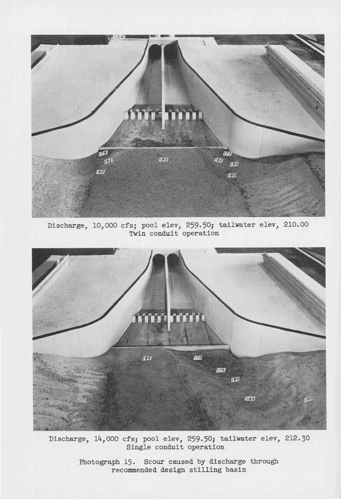
Discharge, 10,000 cfs; pool elev, 259.50; tailwater elev, 210.00 Twin conduit operation
Discharge, 14,000 cfs; pool elev, 259. 50; tailwater elev, 212.30 Single conduit operation
Photograph 15. Scour caused by discharge through recommended design stilling basin

Discharge, 18,000 cfs; pool elev, 259-50; tailvater elev, 213.10
Discharge, 28,000 cfs; pool elev, 259-50; tailvater elev, 214. 70
Photograph 16. Scour caused by discharge through recommended design stilling basin

PLATES

"U r ~ rn
ZOO.O'
100.0 1
:.,1 1$.4 ' SJ.9 1 + zo.T' If'
. . ..
~ ~~ ~ !D:_~ ~ I <JJ.i__ITl
'---H ... ~ (:, -~:..._
f= r-~ £LEV 219.0 ~
~
~ ~
I I 100
100
SECTION A-A
&1.0' I 85.0 1 IS '
14.0' II'"
£LEV 175.0 ;., ::1
Ap \ \
\
200 DIS1'ANC£ IN F'EE T ALONG (: Ot:' 8ASI N
PLAN
£LEV 175.0~
200
Dl $1ANC£. IN FEE T AL.ONC '- Ot:' 8 A.SIN
ELEVATION
JJJ.O ' I
£LEV 1800
' !:! ~ '
~r
300
£LE V 180.0
300
~j ~
~ ..... ~
IONJ £L£V 205.01
I 4 00 ~00
400 ~0
$TILLING BASIN ORIGINAL DESIGN
SCALES PROTOTYPE '1.iio::::.::..C=='"=--..i50===='~6 --ooorr
MODEL ~-o+.oJ~==~----~===-----

"'0 r ~ JTI
1\) E..FT SPFIAY WAL L
Z IO .J
"' ::. .... "' 200 it' ;;; z 0 190 ~ > "' .J
"' 1&0
L EFT S PRAY WA
2 10 .J .. :! t;
200 ~ ;;; z 0
~ >
190
~ "' 1&0
D ISTANCE I N FEET FROM CEN TERLI NE OF BASIN
60 40 zo <!;. zo
4.10 6. ~0 10..10 9 , /S tQ.JO .us• .1~()· .. .. .. 4.10 4 .10 1..10 4 ,10 T.JO ;;;;. ffl• ..... .. ..... 4 .00 W•
-1.10 m · 4 .10 .. 4.2 S .. 4 , /0 .. 3.$0 J .?S 4.00 4 .00 4.00 );;" Ji7 •• .. ..
DISTANCE IN F'EET FROM CENTERLINE OF 8 ASIN
60 40 20 ~ 20 I I I I
S.2J [;J.g, 11.4$ '..!MP 1'11 M J46° m· .. -!.d£ ..... L!.! Z!.l ~ 170° J$2 • Jss• .. ,. 4. ZS 4. 25 4.90 4. f0 S ./0 11s• 175 ° .1$1'. D- 7 4. (0 . 4.20 4.60 4.40 4.40 7iU' 17
,., .. ••
NOTE : F I GURE A BOVE LIN £ IS VEl-OCIT Y IN P ROTOTYPE
F EET PER SECON D .
F ICURE &El..OW l-I N E INDfCAT ES AN CL E OF f l-OW
MEASUR~O O..OCKWlSE FROM DOWNSTREAM DIRECTION.
40 6 0
R I GHT $PRAY WAL L
210 ... "' TEST CONDITIONS
6 ./ .J :!
S.IO .... zoe w w D ISCHA RGE ~Jooo c rs 200 if POOL E L.:EVATIO N Z$~.$0
~ t-!.£ ;;; TAILWATER ELEVI<Tt ON 203.96 16° 16. z
190 0 TWO GONOVITS o 'PERATING
4.~$ ~ ~ 10. ,.. >
~ 3. 1$ 3 .$0 "' r lr 180
40 60 I I
RIGHT SPRAY WALL
2 10 .J TEST CONDITIONS .,
7. / J ~ ::. .... lo• 19 0° 200 ... O ISCH AA.G£ 10 .,000 as if POOL eLEVATION 2.~9.,0
!!.£. 4. 90 ;;; TAILWATER ELE VATION 2 10.00 6 . 7iOo z TWO CONOUtTS OPERATING
190 0
~ .t.zo ~ 18.$0 tgs• >
4. 25 iW it§.. 1&0
~
VELOCITIES AT END SILL ORIGINA L DESIGN 5,000 CFS - 10,000 CFS

DISTA~E !!>& F'EET FAOM C £NTE:RLINE OF &ASIN
60 40 20 .... 20 •o 60
\.EFT SP1tAY W ~ RIGHT SPRJ.Y W._l.\.
l!O .... ~ ~~ I~ ~ (!J_?.§ 5.10 2 10
.,; iW J4()"' J 48° o• u• zo• , ... ... TEST CONDITIONS
3 ~ ~ rUJ ~ w 5.ZS
i t:; ~ ~
OISC ).OARGE IS1 0 00 (; I"S
zoo 161'0 J<ll" .. c• .. ,.. fiiO zoo w PCOI.. ELEVATION 2.~9.~0 ~ "' ... TAILWA'TER ELEVATION 2 t 2 .4S ~ ug '·"' ~ !l:.tJ ~. 40 4110 !&.q ; z 168° 3$J• o• o• .. 700 I!JO• z TWO CON OV!TS OPERATING
Q l•c 1 •• 0
~ !,;.!1 ::/;'. 6 . 4() /2.00 ~./5 Ul 4.25
~ 161' 0 o• o• o• 187• ''"'" ~ 4.10 4.1$ 4.2$ $ ,25 U§. Ul <.2$
18¢ i61' 1'1!' o• o• o• 187• liFo 1&0
DISTANCE IN f EH FFI.OM C ENTEfiti.. INE OF 6A$lN
60 4 0 20 ¢. 20 4() 60
LEFT ~PRAY WALL JU~T $1'AAY W"\.1.
a lo 1,4 () 9.1/J t..1.70 11.10 /J./J g, l/6 7.40 210
;;( JJ6• 348° -.. 7 ... 7T" zr• ~
TEST CONDITIONS
~ 6 . 40 ~ 11.5$ ~ I.I.J.9 ~ ... > O!$GMA!\O! 1&,000 GF~ t; zoo li7o 34 f 0 0. o• o• , .. iW 200 ~ PCOL ELEVATION Z~9.~0
lr ~ .... 4 , .f() g,45 " zs 'OJO "'" ' .. TA!LWATER ELEVATION 2 t3 .10
2 16 1• m· ..... .. .. 187• iii"• • TWO CONCVITS OP ERATi l'I.'G
0 190 0
s :6~~ :;~ 1 .40 ~ U!1 1JP . £D
~ ~ ..- o• o• 1:67• 194 .
; "' UQ il/2 ~ UJl J.,.?j ~ 180 ,., ,.. o• .. .. 181• f$.t• 160
CIS TANCE JN FEET FROM CENT!Rt.!NE OF 8ASIN
6C 4 0 20 <k 20 40 60
LEFT SPRAY WA L AICW'l S PA" V WA\.1.
l!O / 4, J$ 16.10 1~. 9{) 14 . .J$ 16.$<) 16 .40 f.4.JS <1 0 TEST CONDITIONS J 4&• JS.J• o- o- .. -;: 7i"i J
~ 'S , 14.6 6 OISCHAA.GE u.ooo crs
~ ~ !1.li I.Ld2 ~ 117$ IJl:.AP ~
~ tO·O 141~ JH• .. o• .. .,.
~~~· 200 w POOl. i t.. iVATION 2.~~.~ ... TAILWATi.A EL (VATION 2 141 ,70
~ t$1 10 .11!. '!)&> '~ §.:.!..9 ~ ~
• 167 • 1 74° o• .. o• 187~ /94• • TWO CONDUITS OP£RAT!f'"'CO
2 ... ,., 0
~ .. ~ ~ 8.00 w w 4 .1(; 16 ,25
~ 1:, m· 174° .. o• o• ,~.,.
;;: ~ <-M £M Uf) ~ £1fl J, fj
'1) 160 16 7° /14° o• o• o• 187" 114• 1&0
r VELOCITIES AT END SILL )> NOTE F'IGVAE A80V£ L tN£ IS VfL(lC.I TY IN P ROTOTYPe_
-! F£E't ~EFt S£CONb ORIGINAL DESIGN JTI F'tOUR~ &ti..OW L INE INO!CATES .. NCLt OF F'LOW
M(A$VRf0 <:.t.OC:.I<W!$( fR OM 00WN$TR( A"' I>IR.E<:T!ON IS,OOO CFS, 18,000 CFS AND 28,00 0 CFS
w

0 1$ TANC£ IN FEET II ROM CENTE.R&.INE OF 8 A$ 1N
60 40 20 <t. 20 40 60
LEFT S P RAY WALL R IGHT SPRAY WA~L
215 2 15 J J TEST CONDITIONS "' ..
l :1 ... 7,$C 1(.15 16.10 11. 1$ 16.00 10.7!1 8.60
!; .. nr· JiO• $$()• 00 JO• 18° ~ DISCHARGE iO~OOO C F$ ::' 205 205 ~ POOL ELEVATION 259.50 ! :6:: 7. 40 1/.1$ IO.OC II. I() T.Z$ ~ ;!; TAILWATER ELEVATION 2 10 .00 z .1<~8• To Do To"" IF ~~~· z 0 195 195 2 TWO CONDUIT$ OPtRATING
~ ~ ytg 'c~" ~~() 8.>0 $,()() 5.00 s i:; IG7• .JJO• To"" JO• ii'7i w J
U.§ 5.00 ~ ~!0 !.:.ll !J9 ... .. ~· ..
185 167• u • o• o• 187• 94° 185
BASIN FLOOR AND END SILL RAISED 5 FT
DISTANCE IN FEEY FROM c fNl ERI-INE OF BASIN
60 40 20 <t. 20 40 60
LEFT SPRAY WALL RIGHT SPRAY WALL
220 220
.: ... TEST CONDITIONS l ~ ... t;; DISCHARGE 101000 CF'S .. 210 2 10 ~ ~ POOL ELEVATION Z$t. ,O
~ £.1.§ g,$0 ~ 11.10 16.00 9 .8$ 4.2$ ;!; TAILWATER ELEVATION 2 10 .00 172• 348° J$$• Do To ,.. j"j"iO
z ~ TWO CONOUITS OPERATING 2 00 200 0
~ 4 .$0 5 .00 /J.JJ 10.()0 1.3.65 $.00 4.ZJ ~ > 172° W • .1$$• 00 To IF ;no
i:; .. J
~ ./.25 10.00 9 • ./5 ~ £U 5.00 cl .. 190 112• J47• cs;• o• .. u• 181• 190
BASIN FL OOR RAISED 5FT END SILL RAISED lOFT
NOTE : F ICURE ABOVE LINE IS VELOCITY IN PROTOTYPE
FEET PER SECOND .
FICVRE 8ELOW LIN£ IN DICATES ANGLE OF FLOW EFFECT OF STILLING BASIN AND MEASURED CLOCKWISE FROM I>OWNSTREAM DIRECTION.
END SILL ELEVATION ON VELOCITIES AT END SILL

'1)
r ~ I'll
(11
LEFT PftAY WALL
210 -' .. ~
:;; 200 i:'
<! z Q 190 ~ > "' -' "' 1ao
Ot $ TANCE 1N FEET F ROM CENTERl.JN &: OF BASIN
6() 40 zo <t. ·zo 40
6.75 .J.Jo•
!I.ZS l§.d.g I£:!P lMl II.JS .Jto• o• o• o• w
S.2S 77o-
!£d.} 14. ,15 I!:!J /.#..1$ ~ 3to• o- o• o- •••
s.zs ITO•
8.50 10.6$ 11.65 10.65 8.50 280° o- o- o- so•
J.7$ J7o•
r.oo 7.~$ 7.00 r.oo ~ liS• .,... .,... .,...
1~5·
5.25 110•
~ • . $0 T.$0 4 .ZS gj ,. .. o• o• o• Z/0°
STEPS FLARED AT ANGLE OF 120 DEGREES TO SPRAY WALLS
NOT£ : F ICURE ABOVE LINE IS VELOCITY IN PROtOT YPE
FEET PER SECONO.
FICUR£ BELOW LINE lNOIC.,1ES ANGLE OF FLOW
MEASURED CLOCKWtSE FROM DOWNSTREAM DIRECTION,
6()
5 .75 w s.J.I liO•
•.go iio.
5 . 75 ~
S.JS 90•
R IGHT SPRAY WALL
210 _, " TEST CONDITIONS ~ .... "' OI SCHAACE 10 1 0 00 CF'S 200 "' ... POOL ELEVATION 2St.$0 ;::
TAILWATER ELEVATION 210 .00 z
19 0 0
~ TWO CONDUIT$ OP£AATI~G
"' _, "' 180
EFFECT OF FLARE OF STEPS ON VELOCITIES AT END SILL

DISTANCE IN FEET FROM CENTERLINE Of= BASfN
40 20 <t. zo 40
EFT SPRAY WAL RtGHT SPRAY WALL
··~ ~ ~0 !Y!2 u .so ~:~ 210 ... o• .11Q• o• ..,.. ...
TEST CONDITIONS "' "' :f U}. '~!o 8.$() lll.J 8.$() :f
::; 200 o• o- o• o- ::; OISCHARGE 10 10 0 0 CF$ ... zoo
~ ... POOL El..EVAT ION 2~9.50
;; $,()Q 6.2$ s.co ~ #,75 ;; TAILWAT ER EL EVATION .
210.00 .. Oo Oo o• o• z
19t
z TWO CONDUITS OP[RATING 2 190 ~ 1- .1.60 ~ 7. 1$ 4 .1j ~ ~ .. o• F o- o•
~ ... ... 3.2J J.60 T.TJ 3.~0 3.90 ...
teo- :or. o• o• o• o• 180
DISTANCE IN FEe T FltOM C !NTitJ\t..INE OF &ASIN
40 20 <t. 20 40
L EF'T SPRAY WALL RIGHT SPRAY WALL
210 10.74 /Z.50 11.50 120~0 10.74 210 ... o- 00 Oo o• ... TEST CONDITIONS "' "' :::; /().~$ 1.1&2 /#,()()
::1 I~ I~ .. ::;
200 .. o• o• Oo o• 200 "' 0 1$CHAA.GE t8 1 000 CFS
~ ~ POOL EL EVATION 2~9.50
;!; 7.5Q /2.$() 1/ • .ilO J.1 .$0 T.$0 ;; TAII..WATt R ELEVAT ION 2 13.10 ... Oo ... o- o-z z TWO CONDUIT S OPERATINC 2 190 190 2 ,_ I . T$ IJ,;Z4. 12.50 11.14 6.7$ ,_ ~ o- o• .. .. .. ~ ... ... ...
4.7$ 1/.74 11.7# /1.$0 4 . '!$ ... ... ...
ISO o• o• o• o• o• 180
NOTE : F'I GUR.£ AeOv£ \.IN£ IS VE LOCIT Y IN PROTOTYPE
F££T PER SECOND.
F I GURE 6ELOw L-I NE INOtCATE.S ANc:;. t,.E OF FLOW EFFECT OF REDUCTION IN M EASURED Ct..OC~WtSE FROM OOWNSTREAM DIRECTION.
WIDTH OF STILLING BASIN ON VELOCITIES AT END SILL

01STANCE I N FfET FROM CEN TERl.INE OF BASIN
60 M) 20 ~ 20 40 60
l E.Fi SPRAY WALL A IGI'f'T SPRAY WALL
21> 215 ..J ..J
TEST CONDIT IONS ., ; :! ... 8 .75 10.51) 1£:!.9 1£&..5 @d5! 10.00 !:11 ~ w .,.,,. J.Jr• o• o• o• z;; u• OISCH ARGE 10 1000 C: FS if 20> 20~ w ... POO\.. ELEVATlOt.$ 2.~9.~0 ~ $.35 ~ ~ !:lP 8.15 r.so S.J5 1!' TAILWAT £A: El EVATION 2 10.00 z J 40° Jt1Z• o• o• 00 18 ° zo• z 0 ••• • •• 2 TWO CON DUITS OPERATING
~ 3. TO S .Z$ 6.0 0 7.00 6.()0 ~ 4 .ZO .. > J4l 0 J 40 ° 00 .,. 00 zo• 18° > "' w ;:l 4 .3$ ti. ZO 4 . .35 $.()0 4 .60 ~ • .JS !.:.§£
..J w ••• W• J44° o• o• 00 fl. !8• •••
DEFL ECTOR BLOCKS - TYPE c
OISTANCE IN FEEl' f'ROM CENTEFU .. ,N E OF & ASI N
so 40 20 ~ 20 40 &0 I I I I I I
LEFT _5_PRAY WAL L R IGHT SPRAY WAI_L
2 15 2 1> ..J _,
TEST CONDIT IONS ., ., s
~ !:£f' II. S O 9.00 11.15 9.00 8.J5 s ... ... "' 20S
J47° JSJ• 00 o-- ·oo 7- f# O 20> i:l DISCHARGE K>,OOO CFS
It ... POOL EL£ VA.it0N 25.9 .!10
"' 7.Z$ 1.J$ 1 .00
' r.oo 7.15 ~ !:.il ~ TAILWATER ELEVATION 2 10.00
" W • J5JO 00 o- 00" 7• ,..
z TWO CONDUITS OPERATING 0 ••• 19~ 0
~ •. oo 4.60 !:ll.. 4.15 4.50 <1.75 6.00 ~ J~T • J$J• o• 00 o- -;-. 7;0
~ ;;; !d1 3 .Z5 3 . .2.5 J.6o 3.50 J . SO 4 ,00 ~ ISS J47° JSJO o• o• o• 7 • ,,. •••
DEFLECTOR BL OCKS - TYPE D
N OTE : F IGURE A BOVE l,.IN E" 1$ VE L.OCIT Y IN PROTOTYPE
FEET PER SECONO.
FIGVRE SEI..OW ~INE IN O, CATES A NC.t. E Of F\.,OW EFFECT OF DEFLECTOR BLOCKS AT MEASUREO CLOCKWISE FROM DOWNSTREAM DIRECTION.
CONDUIT EXIT PORTALS ON VELOCITIES AT END SILL

LEFT S PRAY WALL
2 10
;;( ~ ,_ "' 200 1:' !!
~ ~
1!10
~ ... 1<0
01$TAN:C! IN F££T ,RON CI!NT£·RL IN!. OF BASIN
eo 20 <k. 20 40
10. 2$ J47•
/().00 10.00 8.65 m· o- o-
~ J~T•
8.2$ !dl !:!e. ~$1• o• o•
J.TS JiC•
5. 4 0 4 .15 5 .$0 To o- ....,..
4./!J 3$0•
3 . 76 .J.75 4 .$0 JSO• o- ..
Lj{' ... J.SO .].25 .3.75 Jso• J40• o•
NOTE . f'ICUA.E A&OVE LJNE tS V!:t.OCIT Y IN PROTOTYPE
FEET PER SECOND.
FIGURE BELOW L INE INDICATES ANGLE OF FLOW
~EASUREO CLOCKWISE. F ROM DOWNSTREAM 0 1R£CnON.
/0.00 10.00 o- -,.-Ul 6.Z$ o• To
4 ,7$ $.40 Oo 00
~ .3.7$ o• JO•
3.25 3.50 zo• JO•
eo
AICHT SPRA'r WA.I..I..
10.25 2 10 7P ..1 TEST CONDITIONS .. 4.25 l -;;;- ,_
DISCH.O.RG€ 101000 CFS zoo ...
1:' POOL ELEVATION a~e.$0
5 .75 !! TAll-WATER EL£VATION ZIO,OO 7F z TWO CONDVITS OPERATtNG
190 0 4.2$ ~ JO•
~ .1.75 ..1 ... !$• 1&0
EFFECT OF WEDGE - SHAPED FILLET AT CONDUIT EXIT PORTALS ON
VELOCITIES AT END SILL


1J r ~ fT1
0
_J <f)
::;: f-UJ w lL
~
z 0
~ > w _J w
230
220
210 f-
200
190
180
170
160
ISO 0
I I I L I I
I I """-. k
~SPRAY WALL WITER-SURFACE PROFILE- DISCHARGE 18,000 CFS~ (TAILWATER ELEV 213.1) I ----~--- ----< r-
1"--.. ...... -- -----f.--r-----..... r-......,..-~ -- ' ·-- r-- ·-_ .......
~ ............... ~
40 80
NOTE: POOL ELEVATION= 259.5
I .! SPLITTER WALl - .L -- -- --r-- -- -- -- --r-.. .-----~---
r--~ ~I\.
~ '-----WATER- SURFACE PROFILE-DISCHARGE 10,000 CFS
(TAILWATER ELEV 210.0)
""', "'"' \ fl r
120 160 200
DISTANCE IN FEET ALONG CENTERLINE
I
240 280
WATER- SURFACE PROFILE RECOMMENDED DESIGN

OIST-.HC.~ $N P'!t!T fROM <::E.NTef\LINI! <# 8A$1N
60 .. 20 ~ 20 ~ 60
E.f'T SPfit.AY WA ' R IC.HT $PRAY WAI..\..
"l 410
~ TEST CONDITIONS
;; " • .Jo~' J21 ,
OISCMA.AG€ $ ; 000 CFS
E ~~:.
~.1$ ';// ~,~ 6 , 1$
· ~ zoo .... 00 , ..
20 0 POOL lil..liVATION 2 5-<J.$ 0
TAILWATEA £LE.VATION ~oa.o$ ~ ~ l.lJ Jo~s 1 .1$ ';;~$ 3:/.~ ~.cs ~
:ur• .JSJ• .. ,.. z TWO CONDUITS OPtRATtN<:i
~ 190 190 0
~ J.PS !..:lJ /,T$ l.dl 1 .1$ Z .15 ~·}: ~ W"· 3s.r .. .. .. 77
~ I w. 1.0() !~ ~ I.OC 1.00 P.15 I&OL ~,,. 'JSJ• .. .. .. T• ,.. •••
OIS TANCE I N FEET ~AOM CENTEAI..INE OF 8A$1N
"' "" 20 ~ .. •o ISO
I..EI'T ~AA't' WALL AICI-(t" S PRAY WALL
2 10 ~::. ,... .... 8.11',) 6 .60 1.10 1.60 ••• TEST CONDIT IONS
.J ;m-. .... .. .... .......- 'W" .J
~ 1.00 6.1$
~
i so!o ~? s0~o .!d:! 1.00 ~
OISCHARGE 1o .. ooo CF"S
200 J.t1• J$3* ,. --;:;-;- u POOL IELEVATION aso.~o 200 ~
~ TAILWATEA £L(VATION 110 .00 i ill !:n ~.IS .t.1S .t.ZS 4.ZS .t.lS ~ z .J.t1• Js.t• .. .. 00 ,. ,..
z T WO CONDUIT S Oi"£1tATING
~ 190 19 0
0
;::. ~~s. Z.TS ~.zs l . U l.ll ~~~5 ~ .. .. .. ,. ;4~~ 2 .75 l.1S l.1S z.tS Z.TS 3. 1$ w
180 ...,. .. o• .. ,. , .. 180
0 1$TANCe. IN f"I!I!!T t'A'OM G!NTfAI..INI! Of' 8 "SIN .., "" 20 <!;.
~· 4 0 ISO
j I I I j I I
,£n .P.AY WA A!CNT SP!tA'I' WALL
••• 1.1.1$ 1$.40 "";? 1!)/! ~~! oi.TS ~~~~ 2 10 ~
W• m· w .J TEST CONDITIONS ;
~4':. :i~~ /j. <IO S . .Jt> 3 .2$ /1.75 J . J$ ~
~ ~ Oi$C~AG€ ••.,ooo CF$
200 o• $• , .. To• 19S• 200 POOL £ L £V.tr.TION 2.S9.SO
T,i~ILWA.T'ER £~£VATI0N Z l3,)0 ! a!P JO.lS /J ,.$!) J.z.s 2.15 JJS J .U ! J #l • ,..,. .... ....... nr• zzo• lfJS• ONE CONOUIT OP! IItATING ~ 190 100 ~ ;: l'. O(J §.:.!.£ 9.~0 "'f! 4 .1'5 J.l$ ~ ~
~ .1#1• ,.,. o• 125° 'i20• 1/1$•
~ ~.1$ 6./S 1.60 .J .. 2S J.25 ~.25 J .JS 180 W• 35J 0 CF' ... m·----m· ,gs• 100
VELOCITIES AT END SILL NOT! ' FIQVI=tl! 480V€ L.-1"-- li !$VELOCITY IN PROTOTY~!
FtE'T P£R s£eowo. RECOMMENDED DESIGN FIGURE el!t..OW \. IN( INOICAT£$ ANGL £ OF FLOW ME~MD CU>CKW1SE FROM I>OWNSTA6AM 0 11\!CTiON. 5,000 CFS , 10,000 CFS AND 14,000 CFS

DIS TANCE \ N HET FRO~ CENTE.RLIN£ OF 9 A$!N
eo 40 20 <t. ZQ 4 Q •• I I I I I I I Ltfi S PAAY W 1..1. R IGK'r $PRAY WALL
. 10 8../.Q. §f:f.. - !N.l ILOJI ~ IJ..& e lo TEST CONDITIONS ~
.)47• o• o• .. ,.. .: > 7.6<1 !Jfl.. ~
, DISCHARGE .. !21/P ~ A.m. = ~
16,<)00 CF"S .. 200
J#"• .JS3• o• .. o• 7' , .. POOL ELEVATION 2bi. SO : 200 1'A!LWA1'ER ElEVATION 2 12 .45
~ ..a J..U DlJ1. UQ. li1J! ~ !,ll ~
' 347• 35J• o• o< .. ,. , .. z TWO CONCVITS OP ERAT ING
2 190 100 Q
~ ll,! .2.M Lff! ~ LiJ l.I§. 4 .21
~ > J47' JSJO o< o• ,. .,... ~
~ iff. Ll1. 1M l.U Ll1. ~ ::: 100 o• 0 o• 7• 100
OISTANC! IN F'U'l' F ROM CENTERLINE OF BASIN .. •• ~ <t. 2 0 40 60 I I I I I •
t.f:FT SPRAV WA Al<iHT $PRAY WA1.\.
2 10 ~·:~. 1/US 11# ¥. {}.41 '¥/ ~ 2 10 T EST CONDITIONS "
Jn> ,. " " ; ,
~. l.iJl &f.' 1J.fJJl ~ MR. Iff, O!SCMARG! t&.ooo c r s
g zoo ">" .. 7• 200 ~ POOL £ L£ VA.l"ION 2.$9 .~0
T.AILWATER ELEVATION Z.IS . IO ! ~. m. $ ,$() 850 550 us .,,
! ........ .... .... ...,... 74' TWO CONDUITS OP ERATING % % 2 l•o ... 0
~ Hf. !ii· ql. ¥- m 3.2$ ~ ~ > o• -r-~ jH. =- ~ = ~ 3.ZI. lf1. ;;:
100 ,.,. •.. , . 100
DISTANCE IN F'£ET !~='ROM CEN TERLINE OF B A.S!N .. 40 20 <t. 20 40 .. LEfT $PRAY WALL
Rl~\o1T S [II>I\AY W'AI..L
2 10 fiP, ~ 1~0! ~ = ~ ~ 2 10
" . .. 7 ' , .. .: TEST CONDITIONS
" , ~:. 1M! ¥. 1~./J.S "'"" '¥/1
, 0 1$CHARG£ .. II$ .. a:a.ooo CFS
J4?• o• ...... ...,. ~ 200 zoo "'
POOl. EL EVATION Z,.9.$0
! ... u o y ,, ... 'lf! .z.n ~ ~
TAILWATER ELEVATION 2 1-4.70
z .. ,. Jn> .... ,.
2 TWO CONOU!T$ OPEA.AT!NG
2 ... "'" 0
~ fij. 11!-. IIUS &SO 10~ us. ¥/. ~ ....... .,... ,... t #()• ;:; ;;! 2 "1-f w U1. ~ ;.p J2$ !fA ~
100 34.10 .. '""' 100
VELOCITIES AT END SILL NOl£ : F' IGURE ABOVE LINE IS VELOCIT Y IN PROTOTYPE
F££'1 PE R S£CONO . RECOMMENDED DESIGN FIQVRE O£LOW l,. INE INOIGATE$ ANGt.£ OF f LOW MI!:A$VAfl> CI.OCt<W!U F llOM ()OWNSTREAM OIR£CTION. 15,000 CFS, 18,000 CFS AND 28,000 C FS
"'U r )> -I rn
..J U)
::;; 1-w w "-
~ z 0
220
210
i= 200 :ff; w ..J w a: w 1-..: 3:: ..J
..: 1-
190
180
I
' '
I
0
I i
I I
I
i I
I/ i / ! I
;
' I I I
! -1----' F-
!
5
I I
' I
i I
I I ;
' I i ---r I I I ,_.....v i ' y
/f I
I /
I I
!
i I
I I I
' !
I
;...--- 1-1--- I
I
10
'
I I I
' I
I I _j._.J l--
I j_..-.--\. I I
!'--- ;ORMAL TA/LWATER
I
'
I I ! ! --I -1-F--
1-1-1-r\: - T i "-._ SPRAY CURVE
' I I
I I I
I
I
15 DISCHARGE IN 1000 CFS
20
I
I i
I
1--f.--
I
I
'
I I I I
I
./ I v
/
v f-' I
25
220
210
..J U)
:::;;
1-w w "-
~ z 0
200 1-:ff;
I
I 30
90
80
w ..J w a: w 1-..: 3:: ..J
..: 1-
TAILWATER CURVES

..J U)
::i: I fw w u.. z z 0
220
215
210
~ 205 > w ..J w a: w ~ ~ ~
200
195
190 2
PLATE 14
v v )
lc1 v / /
()Cj ''j' / I/
~'? 1/
~ v ~I
c; ~"/ ,p ~'? 1/' NORMAL TAILWATER £LEV.
~?/ Ci/ ooo cf/1 rP/ ,I'J.
I "'~'MAL 7i41LWAT£R {o9 if J 1.---- £LEV. rJ'
1/ I I
I/ v \ L v I l /
,\ 1\ I
i\ r..-- .l
t 1\1\ I\
'\
I\ \ " ", " " \ \ ', 1\.
\ ', ['.;: " ~-
\ "· ' '· \
1'--. ', r,
1\ "· "· 1\ I" h 1'\
3 4 5 6 7 8 9 10 VELOCITY IN FEET PER SECOND
LEGEND
-- ORIGINAL DESIGN --- RECOMMENDED DESIGN
NOTE: VELOCITIES MEASURED ONE FOOT ABOVE END SILL.
TAILWATER VS VELOCITY CURVES