OUTFEED SUPPORT - Woodsmith.commedia.woodsmith.com/videoedition/plans/outfeed-table.pdf · The...
6
OUTFEED SUPPORT © 2013 August Home Publishing Co.
-
Upload
duongkhanh -
Category
Documents
-
view
217 -
download
0
Transcript of OUTFEED SUPPORT - Woodsmith.commedia.woodsmith.com/videoedition/plans/outfeed-table.pdf · The...
OUTFEED SUPPORT
© 2013 August Home Publishing Co.
1 WoodsmithPlans.com SN09330 ©2013 August Home Publishing Co. All Rights Reserved.
Table Saw OuTfeed SuppOrT
feaTure prOjecT
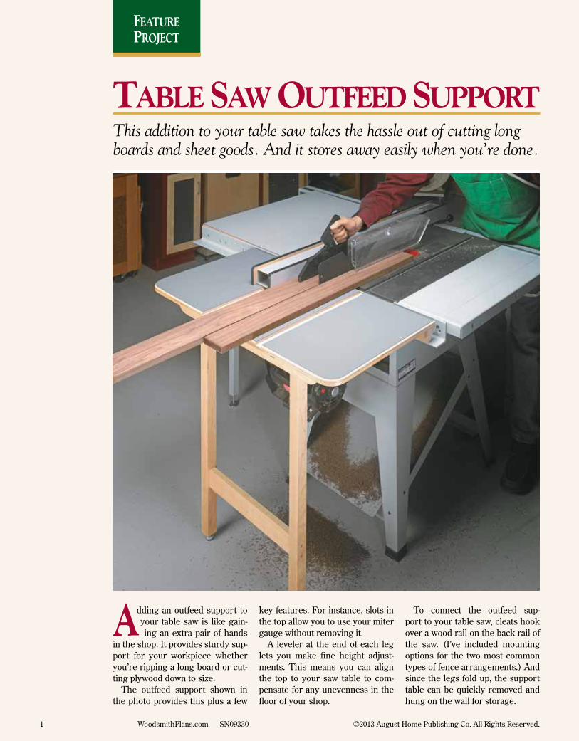
This addition to your table saw takes the hassle out of cutting long boards and sheet goods. And it stores away easily when you’re done.
dding an outfeed support to your table saw is like gain-ing an extra pair of hands
in the shop. It provides sturdy sup-port for your workpiece whether you’re ripping a long board or cut-ting plywood down to size.
The outfeed support shown in the photo provides this plus a few
key features. For instance, slots in the top allow you to use your miter gauge without removing it.
A leveler at the end of each leg lets you make fine height adjust-ments. This means you can align the top to your saw table to com-pensate for any unevenness in the floor of your shop.
To connect the outfeed sup-port to your table saw, cleats hook over a wood rail on the back rail of the saw. (I’ve included mounting options for the two most common types of fence arrangements.) And since the legs fold up, the support table can be quickly removed and hung on the wall for storage.
A
2 WoodsmithPlans.com SN09330 ©2013 August Home Publishing Co. All Rights Reserved.
plastic laMiNatE cuts dowN oN FRictioN aNd
allows woRkpiEcE to slidE sMoothly
acRoss top
SIDE VIEW (CLOSED)
SIDE VIEW (OPEN)
lEg assEMbly attachEs to
thE tablE with utility hiNgEs
lEVElERs allow adJustMENt FoR
uNEVEN shop FlooRs
sizE thE lENgth oF thE lEgs to Match thE suppoRt to thE hEight oF youR saw
FoR Easy attachMENt aNd REMoVal, clEats oN thE top Fit oVER a wood Rail MouNtEd
oN thE saw
dadoEs Match MitER gaugE slots oN
saw tablE
plywood top pRoVidEs stablE outFEEd suppoRt
stop holds lEgs iN VERtical
positioN
Notch iN tablE allows MoVEMENt oF bladE guaRd/splittER FoR
aNglEd cuts
SECtION VIEW
(LEVELEr)
lEgs Fit sNugly agaiNst
stop
lEgs Fold Flat FoR Easy stoRagE
thREadEd iNsERt
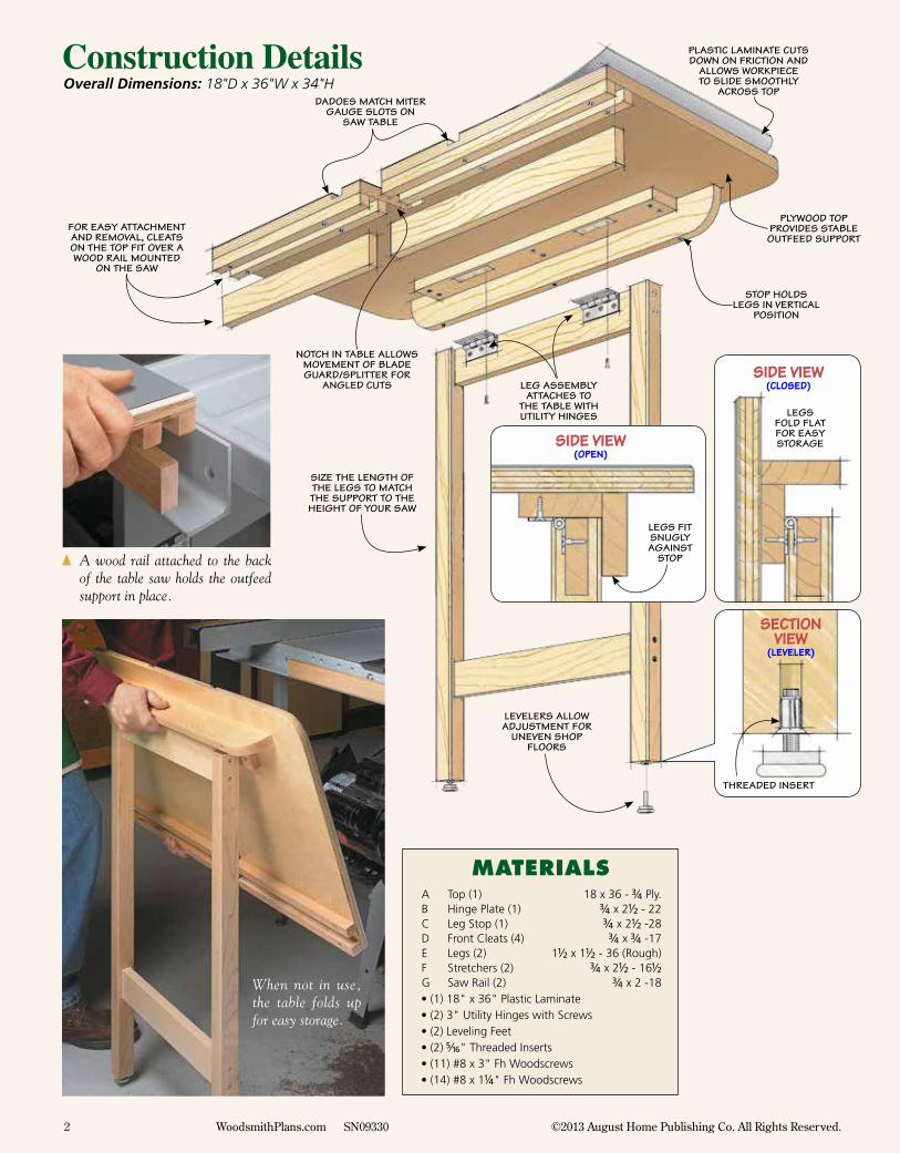
Overall Dimensions: 18"D x 36"W x 34"HConstruction Details
{ A wood rail attached to the back of the table saw holds the outfeed support in place.
When not in use, the table folds up for easy storage.
MaterialsA Top (1) 18 x 36 - #/4 Ply.B Hinge Plate (1) #/4 x 2!/2 - 22C Leg Stop (1) #/4 x 2!/2 -28D Front Cleats (4) #/4 x #/4 -17E Legs (2) 1!/2 x 1!/2 - 36 (Rough)F Stretchers (2) #/4 x 2!/2 - 16!/2G Saw Rail (2) #/4 x 2 -18
• (1) 18" x 36" Plastic Laminate • (2) 3" Utility Hinges with Screws • (2) Leveling Feet • (2) %/16" Threaded Inserts • (11) #8 x 3" Fh Woodscrews • (14) #8 x 1!/4" Fh Woodscrews
3 WoodsmithPlans.com SN09330 ©2013 August Home Publishing Co. All Rights Reserved.
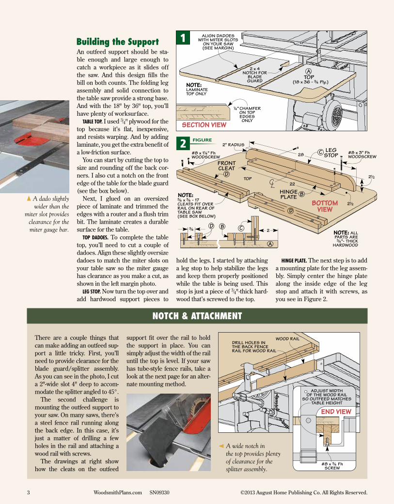
An outfeed support should be sta-ble enough and large enough to catch a workpiece as it slides off the saw. And this design fills the bill on both counts. The folding leg assembly and solid connection to the table saw provide a strong base. And with the 18" by 36" top, you’ll have plenty of worksurface.
Table Top. I used 3⁄4" plywood for the top because it’s flat, inexpensive, and resists warping. And by adding laminate, you get the extra benefit of a low-friction surface.
You can start by cutting the top to size and rounding off the back cor-ners. I also cut a notch on the front edge of the table for the blade guard (see the box below).
Next, I glued on an oversized piece of laminate and trimmed the edges with a router and a flush trim bit. The laminate creates a durable surface for the table.
Top DaDoes. To complete the table top, you’ll need to cut a couple of dadoes. Align these slightly oversize dadoes to match the miter slots on your table saw so the miter gauge has clearance as you make a cut, as shown in the left margin photo.
leg sTop. Now turn the top over and add hardwood support pieces to
hold the legs. I started by attaching a leg stop to help stabilize the legs and keep them properly positioned while the table is being used. This stop is just a piece of 3⁄4"-thick hard-wood that’s screwed to the top.
Hinge plaTe. The next step is to add a mounting plate for the leg assem-bly. Simply center the hinge plate along the inside edge of the leg stop and attach it with screws, as you see in Figure 2.
Building the Support
NOTCH & ATTACHMENT
There are a couple things that can make adding an outfeed sup-port a little tricky. First, you’ll need to provide clearance for the blade guard/splitter assembly. As you can see in the photo, I cut a 2"-wide slot 4" deep to accom-modate the splitter angled to 45°.
The second challenge is mounting the outfeed support to your saw. On many saws, there’s a steel fence rail running along the back edge. In this case, it’s just a matter of drilling a few holes in the rail and attaching a wood rail with screws.
The drawings at right show how the cleats on the outfeed
support fit over the rail to hold the support in place. You can simply adjust the width of the rail until the top is level. If your saw has tube-style fence rails, take a look at the next page for an alter-nate mounting method.
‹ A wide notch in the top provides plenty of clearance for the splitter assembly.
{ A dado slightly wider than the
miter slot provides clearance for the miter gauge bar.
2 FIGURE
1
4 WoodsmithPlans.com SN09330 ©2013 August Home Publishing Co. All Rights Reserved.
DCLEATS LEg ASSEMBLy
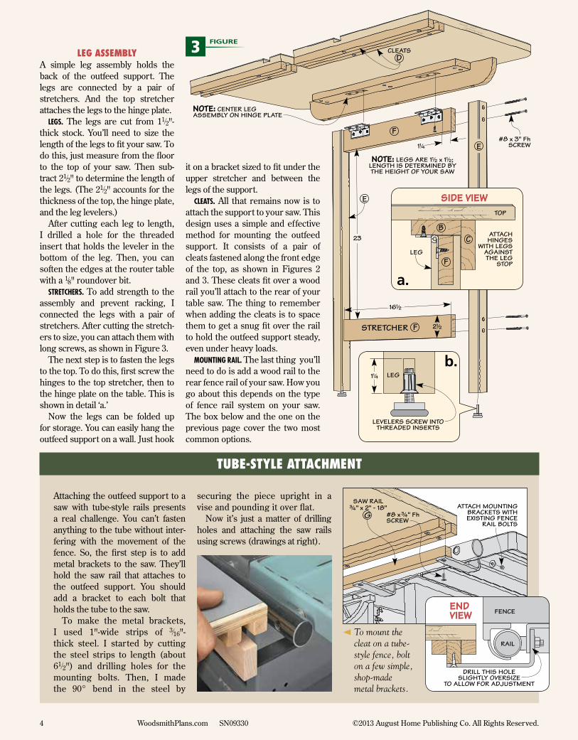
A simple leg assembly holds the back of the outfeed support. The legs are connected by a pair of stretchers. And the top stretcher attaches the legs to the hinge plate.
legs. The legs are cut from 11⁄2"-thick stock. You’ll need to size the length of the legs to fit your saw. To do this, just measure from the floor to the top of your saw. Then sub-tract 21⁄2" to determine the length of the legs. (The 21⁄2" accounts for the thickness of the top, the hinge plate, and the leg levelers.)
After cutting each leg to length, I drilled a hole for the threaded insert that holds the leveler in the bottom of the leg. Then, you can soften the edges at the router table with a 1⁄8" roundover bit.
sTreTcHers. To add strength to the assembly and prevent racking, I connected the legs with a pair of stretchers. After cutting the stretch-ers to size, you can attach them with long screws, as shown in Figure 3.
The next step is to fasten the legs to the top. To do this, first screw the hinges to the top stretcher, then to the hinge plate on the table. This is shown in detail ‘a.’
Now the legs can be folded up for storage. You can easily hang the outfeed support on a wall. Just hook
it on a bracket sized to fit under the upper stretcher and between the legs of the support.
cleaTs. All that remains now is to attach the support to your saw. This design uses a simple and effective method for mounting the outfeed support. It consists of a pair of cleats fastened along the front edge of the top, as shown in Figures 2 and 3. These cleats fit over a wood rail you’ll attach to the rear of your table saw. The thing to remember when adding the cleats is to space them to get a snug fit over the rail to hold the outfeed support steady, even under heavy loads.
MounTing rail. The last thing you’ll need to do is add a wood rail to the rear fence rail of your saw. How you go about this depends on the type of fence rail system on your saw. The box below and the one on the previous page cover the two most common options.
TUBE-STyLE ATTACHMENT
G
SAW RAIL#/4" x 2" - 18"
Attaching the outfeed support to a saw with tube-style rails presents a real challenge. You can’t fasten anything to the tube without inter-fering with the movement of the fence. So, the first step is to add metal brackets to the saw. They’ll hold the saw rail that attaches to the outfeed support. You should add a bracket to each bolt that holds the tube to the saw.
To make the metal brackets, I used 1"-wide strips of 3⁄16"-thick steel. I started by cutting the steel strips to length (about 61⁄2") and drilling holes for the mounting bolts. Then, I made the 90° bend in the steel by
securing the piece upright in a vise and pounding it over flat.
Now it’s just a matter of drilling holes and attaching the saw rails using screws (drawings at right).
‹ To mount the cleat on a tube-style fence, bolt on a few simple, shop-made metal brackets.
a.
b.
3 FIGURE
Woodsmith Store800-444-7527
McMaster-Carr630-833-0300mcmaster.com
Wilsonart800-433-3222wilsonart.com
MAIL ORDER
SOURCES
Project SourcesThe table saw outfeed support is a handy project for any workshop. And the nice thing is it doesn’t take long to build and won’t set you back much for the required materials and hardware.
I was able to pick up the hinges, woodscrews, and plastic laminate (Wilsonart D90-60) at a local home center. You should be able to pick up the steel flat stock for making brack-ets for a tube-style fence there as well. Finally, I ordered the leveling feet (62805K33) and threaded inserts (90016A030) from McMaster-Carr.
5 WoodsmithPlans.com SN09330 ©2013 August Home Publishing Co. All Rights Re-served.