OUTDOOR GAS GRILL - mygrillparts.com · entre 8 h et 18 h HNP, du lundi au vendredi et entre 8 h et...
42
Questions, problems, missing parts? Before returning to your retailer, call our customer service department at Canada: 800-648-5864, U.S./Mexico: 800-913-8999, 8 a.m.-5 p.m., PST, Monday- Friday. 1 OUTDOOR GAS GRILL • This instruction manual contains important information necessary for the proper assembly and safe use of the appliance. • Read and follow all warnings and instructions before assembling and using the appliance. • Keep this manual for future reference. SERIAL # ____________________ MFG. DATE _____________ PURCHASE DATE: ____________ MODEL #720-0778B Pages 2 - 42 19000369A1 PARRILLA DE GAS PARA EXTERIORES MODELO #720-0778B Páginas 43 - 83 GRIL À GAZ EXTÉRIEUR MODÈLE 720-0778B Pages 84 - 124
Transcript of OUTDOOR GAS GRILL - mygrillparts.com · entre 8 h et 18 h HNP, du lundi au vendredi et entre 8 h et...

Questions, problems, missing parts? Before returning to your retailer, call our customer service
department at Canada: 800-648-5864, U.S./Mexico: 800-913-8999, 8 a.m.-5 p.m., PST, Monday-
Friday.
1
OUTDOOR GAS GRILL
• This instruction manual contains important information necessary for the proper assembly and safe use of the appliance.
• Read and follow all warnings and instructions before assembling and using the appliance.
• Keep this manual for future reference.
SERIAL # ____________________ MFG. DATE _____________ PURCHASE DATE: ____________
MODEL #720-0778B Pages 2 - 42
19000369A1
PARRILLA DE GAS PARA EXTERIORES
MODELO #720-0778B Páginas 43 - 83
GRIL À GAZ EXTÉRIEURMODÈLE 720-0778B Pages 84 - 124

¿Consultas, problemas, piezas que faltan? Antes de regresar al vendedor, comuníquese con
nuestro departamento de Servicio al Cliente llamando al Canada: 800-648-5864, U.S./Mexico: 800-913-8999, de 8 a.m. a 6 p.m. de lunes a viernes; y de 8 a.m. a 12 p. m. los sábados. Asegúrese de tener
disponible el número de serie, que se encuentra en la parte interna de la puerta frontal de su parrilla.
Des questions, des problèmes, des pièces manquantes? Avant de retourner l’article au
détaillant, communiquez avec le service à la clientèle au Canada: 800-648-5864, U.S./Mexico: 800-913-8999,
entre 8 h et 18 h HNP, du lundi au vendredi et entre 8 h et 12 h, le samedi. Assurez-vous d’avoir votre
numéro de série en main. Ce numéro se situe à l’intérieur de la porte avant de votre barbecue.
2
Table of Contents
Lighting Instruction. . . . . . . . . . . . . . . . . . . .
Care and Maintenance . . . . . . . . . . . . . . . . .
Trouble Shooting . . . . . . . . . . . . . . . . . . . . .
Ordering Parts . . . . . . . . . . . . . . . . . . . . . . . .
Grill Hints . . . . . . . . . . . . . . . . . . . . . . . . . . .
Grill Cooking Chart . . . . . . . . . . . . . . . . . .. .
Grill Recipe Suggestion . . . . . . . . . . . . . . .
Limited Warranty . . . . . . . . . . . . . . . . . . . . .
Natural Gas Conversion. . . . . . . . . . . . . . . .
24-25
26
27-28
29
29
29-30
31-32
33
34-42
Safety Instruction . . . . . . . . . . . . . . . . . . . . .
Package Contents List . . . . . . . . . . . . . . . . .
Hardware Contents . . . . . . . . . . . . . . . . . . . .
Exploded View . . . . . . . . . . . . . . . . . . . . . . . .
Part List . . . . . . . . . . . . . . . . . . . . . . . . . . . .
Assembly Instruction . . . . . . . . . . . . . . . . . .
Gas Hook up . . . . . . . . . . . . . . . . . . . . . . .
Installer Final Check List. . . . . . . . . . . . . . . .
Leak Testing . . . . . . . . . . . . . . . . . . . . . . . .
Operating Instruction . . . . . . . . . . . . . . . . . . .
Grill Lighting Instruction . . . . . . . . . . . . . . . .
3-6
7
8
9
10-11
12-19
20
21
21-22
23
23-24
• El presente manual de instrucciones contiene información importante que lo ayudará a armar el dispositivo correctamente y a utilizarlo de manera segura.
• Ce manuel d’instructions contient d’importantes informations essentielles à un assemblage approprié et sécuritaire de l’appareil.
• Antes de armar y utilizar el dispositivo, lea y siga todas las advertencias e instrucciones.
• Lire et respecter tous les avertissements et toutes les instructions avantl’assemblage et l’utilisation de l’appareil.
• Conserve el presente manual para consultas futuras
• Conserver ce manuel à titre de référence ultérieure.

3
1. Never operate this appliance unattended.
2. Never operate this appliance within 10 ft (3 m) of any structure, combustible material or other gas cylinder.
3. Never operate this appliance within 25 ft (7.5 m) of any flammable liquid.
4. Do not fill cooking vessel beyond maximum fill line.
5. Heated liquids remain at scalding temperatures long after the cooking process. Never touch cooking appliance until liquids have cooled to 115ºF (45ºC) or less.
6. This appliance is not intended for and should never be used as a heater.
7. If a fire should occur, keep away from the appliance and immediately call your fire department. Do not attempt to extinguish an oil or grease fire with water.
DANGER
If you smell gas:
1. Shut off gas to the appliance.2. Extinguish any open flame.3. Open lid.4. If odour continues, keep away from
the appliance and immediately call your gas supplier or your fire department.
WARNING
1. Do not store or use gasoline or other flammable liquids or vapoursin the vicinity of this or any other appliance.
2. An LP cylinder not connected for use shall not be stored in the vicinity of this or any other appliance.
Failure to comply with these instructions could result in a fire or explosion that could cause serious bodily injury, death, or property damage.
Combustion by products produced when using this product contain chemicals known to the States of California to cause cancer, birth defects, or other reproductive harm.
Your grill will be very hot. Never lean over the cooking area while using your grill. Do not touch cooking surfaces, grill housing, lid or any other grill parts while the grill is in operation, or until the gas grill has cooled down after use.
DANGER
Safety Instruction

4
WARNING
ELECTRICAL GROUNDING INSTRUCTIONS for Rotisserie Motor-This appliance is equipped with a plug and should be
plugged directly into a properly grounded receptacle. When installed, must be electrically grounded in accordance with local
codes or in the absence of local codes, with the National Electrical Code, ANSI/NFPA 70 or the Canadian Electrical Code,
CSA C22.1 DO NOT cut or remove the grounding prong from this plug.
1. To protect against electric shock, do not immerse cord or plugs in water or other liquid.
2. Unplug from the outlet when not in use and before cleaning. Allow to cool before putting on or taking off parts.
3. Do not operate any outdoor cooking gas appliance with a damaged cord, plug, or after the appliance malfunctions or
has been damaged in any manner. Contact the manufacturer for repair.
4. Do not let the cord hang over the edge of a table of touch hot surface.
5. Do not use an outdoor cooking gas appliance for purposes other than intended.
6. When connecting, first connect plug to the outdoor cooking gas appliance then plug appliance into the outlet.
7. Use only a Ground Fault Interrupt (GFI) protected circuit with this outdoor cooking gas appliance.
8. Never remove the grounding plug or use with an adapter of 2 prongs.
9. Use only extension cords with a 3 prong grounding plug, rated for the power of the equipments, and approved for
outdoor use with a W-A marking.
Safety Instruction
WARNINGDo not try lighting this appliance without reading the
“LIGHTING INSTRUCTIONS” section of this manual.
CAUTION: Beware of Flashback
TESTED IN ACCORDANCE WITH ANS Z21.58a CSA
1.6a-2008 STANDARD FOR OUTDOOR COOKING GAS
APPLIANCE. THIS GRILL IS FOR OUTDOOR USE ONLY.
CAUTION: Spiders and small insects occasionally
spin webs or make nests in the grill
burner tubes during transit and
warehousing. These webs can lead
to gas flow obstruction, which could
result in a fire in and around burner
tubes. This type of fire is known as
“FLASH-BACK,” and can cause serious damage to your grill
and create an unsafe operating condition for the user.
Although an obstructed burner tube is not the only cause of
“FLASH-BACK,” it is the most common cause.
To reduce the chance of “FLASH-BACK,” you must clean the
burner tubes before assembling your grill, and at least once a
month in late summer or early fall when spiders are most
active. Also perform this burner tube cleaning procedure if
your grill has not been used for an extended period of time. A
clogged tube can be lead to a fire beneath the grill.
Grill Installation CodesCheck your local building codes for the proper method of
installation. In the absence of local codes, this unit should
be installed in accordance with the National Fuel Gas
Code,ANSI Z223.1/NFPA 54,Storage and Handling of
Liquefied Petroleum Gases, ANSI /NFPA B149.2 or CSA
B149.1 Natural Gas and Propane Installation Code, and
the National Electrical Code, ANSI/NFPA 70.
Correct LP Gas Tank Use
LP gas grill models are designed for use with a standard 20
lb (9 kg). Liquid Propane Gas tank, not included with grill.
Never connect your gas grill to an LP gas tank that
exceeds this capacity.
If an external electrical source is utilized: The outdoor
cooking gas appliance, when installed, must be electrically
grounded in accordance with local codes or, in the absence
of local codes, with the National Electrical Code,
ANSI/NFPA 70, or the Canadian Electrical Code, CSA
C22.1.
WARNING
Keep any electrical supply cord and the fuel supply hose
away from any heated surfaces.
NOTE: The normal flow of gas through the regulator and
hose assembly can create a humming noise. A low volume
of noise is perfectly normal and will not interfere with
operation of the grill. If humming noise is loud and
excessive you may need to purge air from the gas line or
reset the regulator excess gas flow device. This purging
procedure should be done every time a new LP gas tank is
connected to your grill.
Visually check the burner flames prior to each use. The
flames should look like this picture. If they do not, refer to the
burner main tenancy part of this manual.

5
Safety Instruction continued
LP-Gas Supply System
• If the information is not followed exactly, a fire resulting in
death or serious injury could occur.
• A 20lb (9 kg) tank of approximately 12-1/4 inches (31 cm) in
diameter by 18-1/4 inches (46 cm) high is the maximum size
LP gas tank to use.
• This safety feature prevents the tank from being overfilled,
which can cause malfunction of the LP gas tank, regulator
and/or grill.
• The LP gas supply cylinder to be used must be constructed
and marked in accordance with the specifications for LP –
Gas cylinder of the U.S. Department of Transportation (DOT)
or the National Standard of Canada ,CAN/CSA –B339,
Cylinders, Spheres and Tubes for Transportation of
Dangerous Goods and Commission .
• The LP gas tank must have a shutoff valve terminating in an
LP valve outlet that is compatible with a Type 1. LP gas
supply cylinder must have a shut off valve terminating in a
valve outlet specified for connection type QCC1 in the
standard for compressed gas cylinder valve outlet and inlet
connection ANSI/CGA-V-1 as applicable. LP gas supply
cylinder must be fitted with an Overfill Protection Device
(O.P.D) The LP gas tank must also have a safety relief
device that has a direct connection with the vapour space of
the tank.
• The tank supply system must be arranged for vapour
withdrawal.
• The LP gas tank used must have a collar to protect the tank
valve.
• Place dust cap on cylinder valve outlet whenever the cylinder
is not in use. Only install the type of dust cap on the cylinder
valve outlet that is provided with the cylinder valve. Other
types of cap or plugs may result in leakage of propane.
• Never connect an unregulated LP gas tank to your gas grill.
• This outdoor cooking gas appliance is equipped with a high
capacity hose/regulator assembly for connection to a
standard 20lb(9 kg) liquid propane cylinder.
• Have your LP gas tank filled by a reputable propane gas
dealer and visually inspected and re-qualified at each filling.
• Do not store a spare LP gas cylinder under or near this
appliance.
• Never fill the cylinder beyond 80 percent full.
• Always keep LP gas tanks in an upright position.
• Do not store or use gasoline or other flammable vapours and
liquids in the vicinity of this or any other appliance.
• Storage of an outdoor cooking gas appliance indoors is
permissible only if the cylinder is disconnected and removed
from the outdoor cooking gas appliance.
• When your gas grill is not in use the gas must be turned off at
LP gas tank.
• The gas must be turned off at the supply cylinder when the
outdoor cooking gas appliance is not in use.
• LP gas tank must be stored outdoors in a well-ventilated area
and out of reach of children. Disconnected LP gas tanks must
not be stored in a building, garage or any other enclosed area.
• Do Not obstruct the flow of ventilation air around the gas grill
housing. Only use the regulator and the hose assembly
supplied with your gas grill. Replacement regulators and hose
assemblies must be those specified in this manual.
• The regulator and hose assembly must be inspected before
each use of the grill. If there is excessive abrasion or wear or
if the hose is cut, it must be replaced prior to the grill being put
into operation. The replacement hose assembly shall be that
specified by the manufacturer.
• Pressure regulator and hose assembly supplied with the
outdoor cooking gas appliance must be used. Never
substitute other types of regulator. Contact customer service
for manufacturer specified replacement parts.
• This outdoor cooking gas appliance is equipped with a
pressure regulator comply with the standard for Pressure
Regulating Valves for LP Gas ANSI/ UL 144.
• Do not use briquettes of any kind in the grill.
• The grill is designed for optimum performance without the use
of briquettes. Do not place briquettes on the radiant as this will
block off the area for the grill burners to vent. Adding
briquettes can damage ignition components and knobs, and
void the warranty.
• Keep the back and side cart free and clear from debris. Keep
any electrical supply cord, or the rotisserie motor cord away
from the heated areas of the grill.
• Never use the grill in extremely windy conditions. If located in
a consistently windy area (oceanfront, mountaintop, etc.) a
windbreak will be required. Always adhere to the specified
clearance.
• Never use a dented or rusty propane tank.
• Keep any electrical supply cord and the fuel supply hose away
from any heated surface.
• While lighting, keep your face and hands as far away from the
grill as possible.
• Burner adjustment should only be performed after the burner
have cooled.
WARNINGYour grill will get very hot. Never lean over the cooking area
while using your grill. Do not touch cooking surfaces, grill
housing, lid or any other grill parts while the grill is in
operation, or until the gas grill has cooled down after use.
Failure to comply with these instructions may result in serious bodily injury.
CAUTION: TO ENSURE CONTINUED PROTECTION
AGAINST RISK OF ELECTRIC SHOCK, CONNECT TO
PROPERLY GROUNDED OUTLETS ONLY, TO REDUCE
THE RISK OF ELECTRIC SHOCK, KEEP EXTENSION
CORD CONNECTION DRY AND OFF THE GROUND.PROPER PLACEMENT AND CLEARANCE OF GRILL • Never use your gas grill in a garage, porch, shed,
breezeway or any other enclosed area. Your gas grill is
to be used outdoors only.
Do Not install this unit into combustible enclosures.
Minimum clearance from sides and back of unit to
combustible construction, 24 inches (61 cm ) from sides
and 24 inches (61 cm) from back.
• DO NOT use this appliance under overhead combustible
surfaces. This outdoors cooking gas appliance is not
intend to be installed in or on recreational vehicles and/or
boats.

6
Safety Instruction continued
INSECT WARNINGSpiders and insects can nest in the burners of this and any
other grill, and cause the gas to flow improperly. This is a
very dangerous condition, which can cause a fire to occur
behind and beneath the valve panel, thereby damaging the
grill and making it unsafe to operate. Inspect the grill at least
twice a year.
WARNING
Keep a spray bottle of soapy water near the gas supply
valve and check the connections before each use.
DO NOT USE ALUMINUM FOIL TO LINE THE GRILL RACKS OR GRILL BOTTOM.
This can severely upset combustion airflow or trap excessive
heat in the control area.
DO NOT LEAVE THE GRILL UNATTENDED WHILE COOKING.
SAFETY PRACTICES TO AVOID PERSONAL INJURY
When properly cared for your grill will provide safe, reliable
service for many years. However, extreme care must be
used as the grill produces intense heat that can increase
accident potential. When using this appliance basic safety
practices must be followed, including the following:
Do not repair or replace any part of the grill unless
specifically recommended in this manual. All other service
should be referred to a qualified technician.
This grill is not intended to be installed in or on recreational
vehicles or boats.
Children should not be left alone or unattended in an area
where the grill is being used. Do not allow them to sit, stand
or play in or around the grill at any time.
Do not store items of interest to children around or below the
grill.
Do not permit clothing, pot holders or other flammable
materials to come in contact with or too close to any grate,
burner or hot surface until it has cooled. The fabric could
ignite and cause personal injury.
For personal safety, wear proper apparel. Loose fitting
garments or sleeves should never be worn while using this
appliance. Some synthetic fabrics are highly flammable and
should not be worn while cooking.
Only certain types of glass, heat-proof glass ceramic,
earthenware, or other glazed utensils are suitable for grill use.
These materials may break with sudden temperature
changes. Use only on low or medium heat settings in
accordance with the manufacturer’s guidelines.
Do not heat unopened food containers. A build-up of
pressure may cause the containers to burst.
Use a covered hand when opening the grill lid.
Never lean over an open grill.
When lighting a burner, pay close attention to what you are
doing. Make certain you are aware of which burner you are
lighting, so your body and clothing remain clear of open
flames.
When using the grill, do not touch the grill rack, burner
grate or immediate surroundings as these areas become
extremely hot and could cause burns. Use only dry
potholders. Moist or damp potholders on hot surfaces may
cause steam burns. Do not use a towel or bulky cloth in
place or potholders. Do not allow potholders to touch hot
portions of the grill rack.
Grease is flammable. Let hot grease cool before attempting
to handle it. Do not allow grease deposits to collect in the
grease tray at the bottom of the grill’s firebox. Clean the
grease tray often.
Do not use aluminum foil to line the grill racks or grill
bottom. This can severely upset combustion air flow or trap
excessive heat in the control area.
For proper lighting and performance of the burners keep
the burner ports clean. It is necessary to clean them
periodically for optimum performance. The burners will only
operate in one position and must be mounted correctly for
safe operation.
Clean the grill with caution. To avoid steam burns, do not
use a wet sponge or cloth to clean the grill while it is hot.
Some cleaners produce toxic fumes or can ignite if applied
to a hot surface.
Turn off grill controls and make certain the grill is cool
before using any type of aerosol cleaner on or around the
grill. The chemical that produces the spraying action could,
in the presence of heat, ignite or cause metal parts to
corrode.
Do not use the grill to cook excessively fatty meats or other
products which promote flare-ups.
Do not operate the grill under unprotected combustible
constructions. Use only in well ventilated areas. Do not use
in buildings, garages, sheds, breezeways or other such
enclosed areas.
Keep the area surrounding the grill free from combustible
materials including, fluids, trash, and vapours such as
gasoline or charcoal lighter fluid. Do not obstruct the flow of
combustion and ventilation air.
WARNING
This outdoor cooking gas appliance is not intended
to be installed in or on boats and other recreational
vehicles.
7
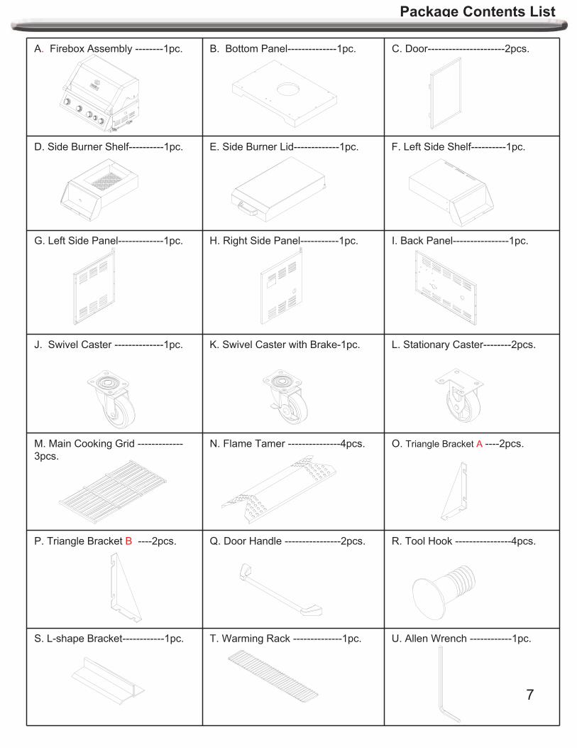
Package Contents List
A. Firebox Assembly --------1pc. B. Bottom Panel--------------1pc. C. Door----------------------2pcs.
D. Side Burner Shelf----------1pc. E. Side Burner Lid-------------1pc. F. Left Side Shelf----------1pc.
G. Left Side Panel-------------1pc. H. Right Side Panel-----------1pc. I. Back Panel----------------1pc.
J. Swivel Caster --------------1pc. K. Swivel Caster with Brake-1pc. L. Stationary Caster--------2pcs.
M. Main Cooking Grid -------------
3pcs.
N. Flame Tamer ---------------4pcs. O. Triangle Bracket A ----2pcs.
P. Triangle Bracket B ----2pcs. Q. Door Handle ----------------2pcs. R. Tool Hook ----------------4pcs.
S. L-shape Bracket------------1pc. T. Warming Rack --------------1pc. U. Allen Wrench ------------1pc.

8
V. Bezel----------------- 1pc. W. Control Knob----------------- 1pc. X. Side Burner Cooking Grid ------1 pc.
Y. Bottle Opener------------1pc. Z. Side Grease Box ---1pc. A1.Grease Box ----1pc.
B1. Main Grease Tray----1pc. C1. Battery ---------1pc. D1. Tank Heat Shield-----1pc.
Hardware Contents
Package Contents List
Pack Description
Required
for
assembly
Extra hardware Total
AA 5/32-in.X10 mm Truss Head Screw With Locking Washer (SS) 10pcs. 2 pcs. 12pcs.
BB 5/32-in.X10 mm Truss Head Screw With Locking Washer
(Black PDC)10 pcs. 2 pcs. 12 pcs.
CC 1/4-in. x 15 mm Truss Head Screw With Locking Washer (SS)35 pcs. 2 pcs. 37 pcs.
DD 1/4-in. Flange Nut 4 pcs. 1 pc. 5 pcs.
EE 5/32-in. x 10 mm Flat Head Screw 13 pcs. 2 pcs. 15 pcs.
FF 1/4-in. x 15 mm Truss Head Screw With Locking Washer
(Black PDC)4 pcs. 1pc. 5 pc.
HH 5/32-in. Flat Washer 6 pcs. 1 pc. 7pcs.
II 1/4-in. Flat Washer 4 pc. 1pc. 5 pc.
JJ black Flat Washer 4 pc. 1pc. 5 pc.
KK Tank Bolt 1pc. / 1pc.
AA BB CC DD EEHH
IIFF JJ
Note: Below table of hardware are KD assembly but hardward in step 6, 8, 10 of instruction are pre-assembly.
KK

Explode View
NG Package View
(Natural gas conversion
kit sold separately)

10
Part List
No. Part (Description)Warranty coverage
QTY No. Part (Description)Warranty coverage
1QTY
1 Main lid 1 1 32 R shape pin 1 4
2 Main lid screw 1 2 33 Flame tamer 1 4
3 Temperature gauge 1 1 34 Main burner 5 4
4 Logo 1 1 35 Main burner igniter wire A 1 1
5 Hood buffer A 1 2 36 Main burner igniter wire B 1 1
6 Flat washer 1 2 37 Main burner igniter wire C 1 1
7 Flange, left 1 1 38 Main burner igniter wire D 1 1
8 Hood buffer B 1 4 39 Rotisserie heat shield 1 1
9 Front baffle 1 1 40 Rear baffle 1 1
10 Rotisserie gas valve 1 1 41 Rotisserie burner 1 1
11 Igniter junction wire 1 1 42Rotisserie burner igniter
bracket1 1
12 Main gas valve 1 4 43 Back panel, top 1 1
13 Main manifold 1 1 44 Rotisserie igniter wire 1 1
14 Main control trim panel 1 1 45Rotisserie orifice w/brass
elbow1 1
15 Main control panel 3 1 46 Rotisserie flex gas line 1 1
16 Bezel A 1 5 47 Side burner lid 1 1
17 Control knob A 1 5 48 Side burner lid handle 1 1
18 Control knob B 1 1 49 Hood buffer C 1 2
19 Bezel B 1 1 50 Side burner cooking grid 1 1
20 Flange, right 1 1 51 Side burner 1 1
21 Regulator LP 1 1 52 Side burner igniter wire 1 1
22 Side burner flex gas line 1 1 53Side burner lid support
bracket1 1
23 Side manifold 1 1 54 Side burner bowl assembly 1 1
24 Grease box 1 1 55 Side burner gas valve 1 1
25 Grease tray 1 1 56 Side burner control panel 1 1
26 Tank heat shield 1 1 57 Spit fork 1 2
27 Side shelf, left 1 1 58 Spit rod 1 1
28 Side shelf control panel 1 1 59 Side burner grease tray 1 1
29 Hook 1 4 60 Tank bolt 1 1
30 Warming rack 1 1 61 Back panel 1 1
31 Cooking grid with hole 1 3 62 Swivel caster with brake 1 1

11
Part List
No. Part (Description)Warranty
coverageQTY No. Part (Description)
Warranty
coverage1
QT
Y
63 Side panel, Left 1 1 79 Triangle bracket A 1 2
64 Bottom panel 1 1 80 Bottle opener 1 1
65 Swivel caster 1 1 81 Rotisserie motor 1 1
66 L shape bracket 1 1 82 Rotisserie motor bracket 1 1
67 Cart frame 1 1 83 Manual 1 1
68 Door magnet 1 2 84 PVC cover 1 1
69 Door handle seat 1 4 85 Natural gas orifice pack 1 1
70 Door handle 1 2 86 KD-assembly hardware pack 1 1
71 Door, left 1 1 87Natural gas regulator
assembly1
72 Door, right 1 1 88Natural gas hose with quick
connector assembly1
73 Lighting rod 1 1 89 6 mm nut driver 1
74 Rubber grommet 1 2 90 Hex wrench 1
75 Electronic igniter module 1 1 91 6 mm wrench 1
76 Side panel, right 1 1 92Truss head screw with
locking washer2
77 Caster 1 2
78Triangle bracket B 1 2

12
Assembly Instructions
2. Door Bracket Assembly
Use two 5/32-in. x 10 mm truss head screws
with locking washers (AA) to attach the L-
shape bracket (door stop) (S) to the bottom
panel (B) as shown in Fig. 2.
3. Side Panel AssemblyUse three 1/4-in. x 15 mm truss head screws
with locking washers (CC) to connect the
bottom of the left side panel (G) to the bottom
panel (B). Make the left side panel flush with
the rear of bottom panel and tighten the
screws as shown in Fig. 3.
Repeat for the right side panel (H).
2X
S
B
Fig. 2
Fig. 3
6X
G
B
H
AA
16X
CC
CC
1. Caster AssemblyMount the casters onto the bottom panel (B) using
sixteen 1/4-in. x 15-mm truss head screws with
locking washers (CC).
The swivel caster with brake (K) should be
positioned under the right rear of the cart bottom
and the swivel caster (J) should be positioned
under right front as shown in Fig. 1.
The two stationary casters (L) should be positioned
under the left side.
Note: The gap of the two stationary casters should
be facing the inside bottom panel.
Turn over the bottom panel for assembling casters.
L
B
K
J
Fig. 1

13
4. Back Panel AssemblyRemove the back panel from the carton. Position the
back panel (I) with the flat side facing outward. Attach
the back panel to the bottom panel (B) with three 1/4-
in. x 15 mm truss head screws with locking washers
(CC) as shown in Fig. 4.
Fig. 4
3X
I
B
Use six 1/4-in. x 15 mm truss head screws with
locking washers (CC) to connect the back panel (I)
to the right and left side panels as shown in Fig. 5.
Fig. 5
5. Door and Firebox AssemblyRemove the firebox assembly (A) from the carton
and carefully place onto the grill cart, at the same
time keeping the top door hinge in place as shown
in Fig. 6.
Fig. 6A
Grill Cart
CAUTION The firebox assembly is heavy and will require two or more people to lift and position onto grill cart. Failure to do so may result in injury.
Note: Take care when moving the firebox
assembly as the bottom flanges can be bent,
which would misalign the holes.
6X
Assembly Instructions
I
CC
CC

14
Attach the firebox assembly (A) to the grill
cart using four 1/4-in. x 15 mm truss head
screws with locking washers (CC)
Note: Two screws with two washers for
each side of cart as shown in Fig. 7
Fig. 7A
2X
6. Door Triangle Bracket Assembly
a) Loosen but do not remove the four screws which were pre-
assembled on the Left Side Panel (G) and cart frame, two
screws on cart Right Side Panel (G) and two on the cart
frame. Align the holes of the triangle bracket B (P1) with
screws on Left side panel (G) and cart frame.
b) Tighten the screws previously loosened in step 6a) as
shown in Fig.8
c) Repeat the steps a) and b) for attaching the triangle bracket
A (O2) to the Right Side Panel (H) and cart frame.
d) Loosen but do not remove the four screws which were pre-
assembled on the Left Side Panel (G) and Bottom Panel (B),
two screws on cart Right Side Panel (G) and two on the
Bottom Panel (B). Align the holes of the triangle bracket A
(O1) with screws on Left Side Panel (G) and Bottom Panel
(B).
e) Tighten the screws previously loosened in step 6d) as
shown in Fig.8
f) Repeat the steps d) and e) for attaching the triangle bracket
B (P2) to the Right Panel (H) and bottom Panel (B)
Fig.8
O1
7. Door AssemblyAttached the door handle (Q) to the each door (C)
using eight 5/32-in. x 10 mm truss head screws
with locking washers (AA) as shown in Fig. 9
8X
T
Fig.9
G
Assembly Instructions
16X
B
O2
P1
P2
H
AA

2X
15
Fig.11
Attach the two door hinges to the flange using
twelve 5/32-in. x 10 mm flat head screws (EE)
as shown in Fig. 10.
Fig. 10
12XHINT: Six screws for each door
8b) Attach the Side burner lid (E) to Side
burner shelf (D) using four 5/32-in.x 10 mm
Truss head screws with locking washers (BB)
as shown in Fig.12
4X
Fig.13
8c) Attach two tools hooks (R) to side burner shelf
using two 1/4 -in. flange nut (DD) and two black
flat-washers (JJ) as shown in Fig.13
8. Right Side Burner Shelf Assembly
8a) Loosen the 2 screws which are pre-
assembled onto the firebox right panel, but do
not remove completely, as shown in Fig.11.
(HINT: Instructions for these loosened screws
are shown in the next few steps.)
2X
Assembly Instructions
Fig.12
E
D
R
BB
EE
DD JJ

16
8d). Align the bottom key holes on side burner shelf (D)
with 2 loosened screws on right side panel. Attach the
side burner bowel to the cart with the two loosened
screws on the side panel as shown in Fig.14
Tip: This step is meant to help with the installation but
does not depend solely on the two screws to hold the
weight of the side burner shelf.
D
Fig.14
Fig.15
2X
Assembly Instructions
9. Left Side Shelf Assembly
Repeat step 8 for the left side shelf (F). Screw
bottle opener on left side shelf.
8e). Use two 1/4-in. x 15 mm truss head screws
(FF) and two 1/4-in. flat washer (II) to keep the
right side burner shelf in place (these two 1/4-in
screws are screwed through the front and the
rear screw holes which are located on the top of
right side burner shelf). See Fig. 15.
Note: The top 2 screws of the firebox should be
screwed from inside to outside for right side
burner shelf. But bottom 2 screws should be
tightened from outside to inside.
8f). Use one 5/32-in. x 10 mm truss head screw (BB)
and one 5/32-in. flat washer (HH) to screw the middle
screw hole in the top of right side burner shelf.
Attach right side burner control panel to the main control
panel by using one 5/32-in. x 10 mm truss head screw
(BB) and one 5/32-in flat washer (HH) as shown in
Fig. 15.
Note: The top 1 screw of the firebox should be screwed
from inside to outside for right side burner shelf. But
bottom 1 screw should be tightened from outside to
inside.
1X
1X
BB
FF
BBHH
1X
1X
HH
II
2X

17
Assembly Instructions
2X
Fig.1610. Side Burner Valve InstallationLoosen the "C" bracket on the burner tube located on
the underside of the side shelf bowl by removing the
screw holding it in place. Turn the "C" bracket so the
opening of the side burner tube is exposed.
Loosen the two screws completely which are pre-
attached to the valve. Then insert the side burner
valve into the side burner shelf control panel and
tighten it with the two screws and washers as shown
in Fig. 16.
Return to the underside of the side
burner and turn the "C" bracket to close
the gap in the front opening of the side
burner tube. Tighten screw to secure.
as shown in Fig.17
11.Side Burner Knob Assembly
Locate the small opening on the underside of
the knob (W), behind the rubber grip and peel
the rubber grip back carefully.
Insert the Allen wrench (U) into the hole and into
the set screw, positioned for tightening.
Insert valve stem into knob and tighten the set
screw as shown in Fig. 18
Fig.17
Fig.18
VV
U
W

18
12.Igniter Wire Installation
Insert the side burner ignition wire to the ignite module
as shown in Fig.19
Note: You only need to insert the side burner ignition
wire, the other five wires have been pre-assembled.
Reminder: While completing igniter wire
installation, make sure there is a 3 mm
gap between the igniter pin and the side
burner, so that it ignites easily.
SB igniter wire
13. Battery Assembly
Unscrew the electronic igniter button and
place the battery (C1) into the housing
with positive terminal (+) facing outward.
Replace the ignition button after the
battery has been installed as shown in
Fig.20
14. Grease Tray, Greasy Box Assembly
Fig.19
Assembly Instructions
Z
A1
Fig.21
Fig.20
D1
BB
14b) Place the side grease box (Z),
main grease tray (B1) with Tank
heat shield (D1) and Grease box
(A1) from the rear of grill as shown
in Fig.21
14a) Use two 5/32-in.X10 mm Truss
Head Screws (BB) and two 5/32-in flat
washers (HH) to fix the main grease
tray (B1) and tank heat shield(D1) as
shown in Fig.21
B1
C1
2X 2X
HH

19
15. Flame Tamers, Cooking Grids Installation Place the flame tamers (N), main cooking grids (M),
side burner cooking grid (X) and warming rack (T) into
the grill as shown in Fig. 22
Fig.22
16. Liquid Propane Tank Installation Place the liquid propane tank into the hole
in the bottom panel and tighten the tank
bolt (KK) at the back of the grill to secure
as shown in Fig. 23
Note: Screw the tank bolt at the back of
grill, then insert one 5/32-in.x 10 mm
truss head screw (EE) and one 5/32 flat
washer (HH) into tank bolt prior to placing
the liquid propane tank.
Fig 23
KK
1X
KK
1X
EE
T
N
M
Assembly Instructions
X
1X
HH

20
Gas Hook - Up
NEVER CONNECT AN UNREGULATED GAS
SUPPLY LINE TO THE APPLIANCE. USE THE
REGULATOR/HOSE ASSEMBLY SUPPLIED.
This is a liquid propane configured grill. Do not attempt
to use a natural gas supply unless the grill has been
reconfigured for natural gas use.
Total gas consumption (per hour) of this stainless
steel gas grill with all burners on “HIGH”:
Main burner 48,000 Btu/hr
Sear burner 15,000 Btu/hr
Rear burner 13,000 Btu/hr
Total 76,000 Btu/hr
L.P. TANK REQUIREMENT
A dented or rusty L.P. tank may be hazardous and
should be checked by your L.P. supplier. Never use a
cylinder with a damaged valve. The L.P. gas cylinder
must be constructed and marked in accordance with
the specifications for L.P. gas cylinders of the U.S.
Department of Transportation (DOT) or the National
Standard of Canada, CAN/CSA-B339, Cylinders,
Spheres and Tubes for Transportation of Dangerous
Goods; and Commission, as applicable. Overfilling
prevention device (OPD) shall be provided on cylinder
& QCCI connection on the cylinder valve, ANSI/CGA-
V-1. The cylinder supply system must be arranged for
vapour withdrawal. The cylinder must include a collar to
protect the cylinder valve. The cylinder must be
provided with a shut-off valve terminal in an L.P.
gas supply cylinder valve outlet specified, as applicable,
for connection type QCC1 in the standard for
compressed gas cylinder valve outlet and inlet
connection ANSI/CGA-V-1.Manifold pressure: 11”(27.94 cm) water column (W.C.).
L.P. GAS HOOK-UPEnsure that the black plastic grommets on the LP
cylinder valve are in place and that the hose does not
come into contact with the grease tray or the grill head.
CONNECTIONYour stainless steel grill is equipped with gas supply
orifices for use only with liquid propane gas. It is also
equipped with a high capacity hose/regulator assembly
for connection to a standard 20lb. (9 kg) L.P. cylinder
18 1/4” (46.35 cm) high, 12-1/4”(31 cm) diameter). To
connect the L.P. gas supply cylinder, please follow the
steps below:
1. Make sure tank valve is in its full off position (turn
clockwise to stop)
2. Check tank valve to assure it has proper external
male threads (type 1 connection per ANSIZ21.81)
3. Make sure all burner valves are in their off position.
4. Inspect valve connections, port, and regulator
assembly. Look for any damage or debris. Remove
any debris. Inspect hose for damage. Never attempt
to use damaged or obstructed equipment. See your
local L.P. gas dealer for repair.
5. When connecting regulator assembly to the valve,
hand tighten the quick coupling nut clockwise to a
complete stop. Do not use a wrench to tighten. Use
of a wrench may damage the quick coupling nut and
result in a hazardous condition.
6. Open the tank valve fully (counterclockwise). Apply
the soap solution with a clean brush to all gas
connections. See below. If growing bubbles appear
in the solution the connections are not properly
sealed. Check each fitting and tighten or repair as
necessary.
7. If you have a gas connection leak you cannot repair,
turn gas OFF at supply tank, disconnect fuel line
from your grill and call Canada: 800-648-5864,
U.S./Mexico: 800-913-8999 or your gas supplier
for repair assistance.
8. Also apply soapy solution to the tank seams. See
below. If growing bubbles appear, shut tank OFF
and do not use or move it! Contact an LP gas
supplier or your fire department for assistance.
To disconnect L.P. gas cylinder:
1. Turn the burner valves off.
2. Turn the tank valve off fully (turn clockwise to stop).
3. Detach the regulator assembly from the tank valve by
turning the quick coupling nut counterclockwise.

21
Installer Final Check List
Minimum clearance from sides and back of unit to combustible construction, 24 inches (61 cm)from sides and 24 inches (61 cm) from back
All internal packaging removed.
Knobs turn freely.
Burners are tight and sitting properly on orifices.
Pressure regulator connected and set. Gas connections to grill using hose and regulator assembly provided (pre-set for 11.0” water column).
Unit tested and free of leaks.
User informed of gas supply shut off valve location
USER, PLEASE RETAIN THIS MANUAL FOR FUTURE REFERENCE.
PROPANE CYLINDER CAUTIONS
a) Do Not store a spare LP-gas cylinder under or near this appliance.
b) NEVER fill the cylinder beyond 80 percent full.
c) If the information in “a” and “b” is not followed exactly, a fire or explosion causing death or serious injury may occur.
Leak Testing
GENERALAlthough all gas connections on the grill are leak
tested at the factory prior to shipment, a complete gas
tightness check must be performed at the installation
site due to possible mishandling in shipment, or
excessive pressure unknowingly being applied to the
unit. Periodically check the whole system for leaks
following the procedures listed below. If the smell of
gas is detected at anytime you should immediately
check the entire system for leaks.
BEFORE TESTINGMake sure that all packing material is removed from
the grill including tie-down straps.
DO NOT SMOKE WHILE LEAK TESTING.NEVER PERFORM LEAK TEST WITH AN OPEN FLAME.Make a soap solution of one part liquid detergent and
one part water. You will need a spray bottle, brush, or
rag to apply the solution to the fittings. For the initial
leak test, make sure the L.P. cylinder is 80% full.
TO TEST 1. Make sure the control valves are in the “OFF”
position, and turn on the gas supply.
2. Check all connections from the LP gas
regulator and supply valve up to and including
the connection to the manifold pipe assembly
(the pipe that goes to the burners). Soap
bubbles will appear where a leak is present.
3. If a leak is present, immediately turn off the gas
supply and tighten the leaky fittings.
4. Turn the gas back on and recheck.
5. Should the gas continue to leak from any of the
fittings, turn off the gas supply and contact
customer service at Canada: 800-648-5864,
U.S./Mexico: 800-913-8999 .
Only those parts recommended by the manufacturer
should be used on the grill.
Substitution will void the warranty. Do not use the grill
until all connections have been checked and do not leak.
GAS FLOW CHECK
Each grill burner is tested and adjusted at the factory
prior to shipment; however, variations in the local gas
supply may make it necessary to adjust the burners. The
flames of the burners should be visually checked.
Flames should be blue and stable with no yellow tips,
excessive noise or lifting. If any of these conditions exist,
check to see if the air shutter or burner ports are blocked
by dirt, debris, spider webs, etc. If you have any
questions regarding flame stability, please call customer
service Canada: 800-648-5864, U.S./Mexico: 800-913-
8999 .
ALWAYS CHECK FOR LEAKS AFTER EVERY L.P. TANK CHANGE
Check all gas supply fittings for leaks before each use. It is handy to keep a spray bottle of soapy water near the shut-off valve of the gas supply line. Spray all the fittings. Bubbles indicate leaks.

22
Leak Testing continued
CAUTIONS
Place dust cap on cylinder valve outlet when the cylinder is not in use. Only install the type of dust cap on the cylinder valve outlet that is provided with the cylinder valve. Other types of caps or plugs may result in leakage of propane.
The gas must be turned off at the supply cylinder when the unit is not in use.
If the appliance is stored indoors the cylinder must be disconnected and removed from the appliance. Cylinders must be stored outdoors in a well-ventilated area out of the reach of children.
Your grill is ready to use!

TO MATCH LIGHT THE GRILL
If the burner will not light after several attempts then the
burner can be match lit.
Match light extension rod is located on the inside panel of
the door.
If you’ve just attempted to light the burner with the igniter,
allow 5 minutes for any accumulated gas to dissipate.
Keep your face and hands as far away from the grill as
possible.
Insert a lit match attached to the lighting rod through the
cooking grids to the burner.
Press the control knob and rotate left to the HIGH/ON
setting continue to press the knob until the burner ignites.
Burner should light immediately.
If the burner does not light in 5 seconds turn the knob off,
wait 5 minutes and try again.
23
Operating Instructions
GENERAL USE OF THE GRILL AND ROTISSERIE
Each main burner is rated at 12,000 Btu/hr. The main
grill burners encompass the entire cooking area and
are side ported to minimize blockage from falling
grease and debris. The igniter knobs are located on
the lower centre portion of the valve panel. Each rotary
igniter is labeled on the control panel.
USING THE GRILL
Grilling requires high heat for searing and proper
browning. Most foods are cooked at the “HIGH” heat
setting for the entire cooking time. However, when
grilling large pieces of meat or poultry, it may be
necessary to turn the heat to the lower setting after the
initial browning. This cooks the food through without
burning the outside. Foods cooked for a long time or
foods basted with a sugary marinade may need the
lower heat setting near the end of the cooking time.
NOTE: This grill is designed to grill efficiently without
the use of lava rocks or briquettes of any kind. Heat is
radiated by the stainless steel flame tamers positioned
above each burner.
NOTE: The hot grill sears the food, sealing in the juices.
The more thoroughly the grill is preheated, the faster
the meat browns and the darker the grill marks.
DO NOT LEAVE THE GRILL UNATTENDED WHILE COOKING.
WARNING: IMPORTANT!
USING THE SIDE BURNER
Inspect the gas supply hose prior to turning the gas “ON.”
If there is evidence of cuts, wear or abrasion, it must be
replaced prior to use. Do not use the side burner if the
odour of gas is present.
Grill Lighting Instructions
WARNING: IMPORTANT!BEFORE LIGHTING…Inspect the gas supply hose prior to turning the gas
“ON.” If there is evidence of cuts, wear, or abrasion,
it must be replaced prior to use. Do not use the grill
if the odour of gas is present. Only the pressure
regulator and hose assembly supplied with the unit
should be used.
Never substitute regulators and hose assembly for
those supplied with the grill. If a replacement is
necessary, contact the manufacturer for proper
replacement. The replacement must be that
specified in the manual.
WARNING: Always keep your face and body as
far away from the burner as possible when
lighting.
TO LIGHT THE MAIN BURNER
Make sure all knobs are “OFF” then turn on the gas
supply from the LP (Liquid Propane) tank. Always
keep your face and body as far from the grill as
possible when lighting.
Your grill has an exclusive patented built-in ignition.
The igniter is built into the valve. To ignite each
burner simply push and turn the control knobs to the
HI setting, you will hear the valve click as it sends a
spark to the pilot flame. If the burner does not light
wait 5 minutes for any excess gas to dissipate and
then retry.
TO LIGHT THE SEARING SIDE BURNER
To light the searing side burner, remove any cooking
utensils from the burner grate. Push and turn the control
knob counterclockwise to the “IGNITE/ON” position. If the
burner does not light, turn the control knob to “OFF.” If the
smell of gas is detected and the igniter is not functioning,
immediately turn the control knob “OFF.” Allow 5 minutes
for any accumulated gas to dissipate. If the side burner
igniter is not functioning, see the following section for
match lighting.

Make sure the lid is open.
Push and turn Main Burner knob slowly to
IGNITE/HIGH,. Keep knob pressed in until the burner
is lit.
If burner does not light within 5 seconds, turn the knob
to OFF and repeat the lighting instruction.
If burner does not light up after step 3, turn the knob to
OFF, wait 5 minutes, and repeat the lighting procedure
or light by match. 24
Grill Lighting Instructions continued
TO MATCH LIGHT THE SIDE BURNER
Hold a lit extended match near the side burner ports, turn
the control knob counterclockwise to “IGNITE/HI.” Move
your hand immediately once the burner is lit. Rotate the
control knob to the desired setting.
Keep a spray bottle of soapy water near the gas supply valve and check the connections before each use.
Do not attempt to light the grill if odour of gas is present. Call for service Canada: 800-648-5864,
U.S./Mexico: 800-913-8999
FLAME CHARACTERISTICS
Check for proper burner flame characteristics.
Burner flames should be blue and stable with no yellow
tips, excessive noise, or lifting. If any of these conditions
exist call our customer service line. If the flame is yellow,
it indicates insufficient air. If the flame is noisy and tends
to lift away from the burner, it indicates too much air.
Each burner is adjusted prior to shipment; however, variations in the local gas supply may make minor adjustments necessary.
Visually check the burner flames prior to each
use. The flames should look like this picture, If
they do not, refer to the burner maintenance
part of this manual.
Lighting Instructions
Note: Remove all packaging, including straps, before using the grill
1
2
3
4
Main Burners
Rear Burner
OFF
OFF
1
3
2
IGNITE / ON
IGNITE / ON
1
2
OFF OFFOFF
OFF
IGNITE / HI
OFF
Sear Burner
IGNITE / HIGH
LOW
LOW LOW LOW LOWLOW
IGNITE / HIGHIGNITE / HIGHIGNITE / HIGHIGNITE / HIGH

25
Lighting Instructions continued
IGNITE / ON
1
2
OFF Make sure the lid is open.
Push and slowly turn the Rear Burner knob to IGNITE/ON
position. Keep knob pressed in until the burner is lit. Once
it is lit, continue to press and hold for another 15 seconds to
ensure the burner stays lit.
If burner does not light within 5 seconds, turn the knob to
OFF position and repeat the lighting procedure.
If burner fails to light after step 3, turn the knob to OFF
position, wait 5 minutes, then repeat the lighting procedure
or light by match.
12
3
1. If the burner will not light after several attempts them the burner can be match lit, before using the match
allow 5 minutes for any accumulated gas to dissipate.
2. Clip a paper match on one end of the lighting rod.
3. Light match.
4. Hold lighting rod and insert lighted match right next to the burner ports or ceramic file.
5. Push and turn the designated control knob to IGNITE/HIGH.
6. Burner should ignite immediately.
Match light
4
Main burner
Rear burner/Sear burner

1. Keep outdoor cooking gas appliance area clear and
free from combustible materials, gasoline and other
flammable vapours and liquids.
2. Do not obstruct the flow of combustible and
ventilation air.
3. Keep the ventilation openings of the cylinder
enclosure free and clear from debris.
26
Care and Maintenance
STAINLESS STEEL
There are many different stainless steel cleaners available.
Always use the mildest cleaning procedure first, scrubbing in
the direction of the grain. Specks of grease can gather on the
surfaces of the stainless steel and bake on to the surface and
give the appearance of rust. For removal use a mild abrasive
pad in conjunction with a stainless steel cleaner.
GRILL GRATEThe easiest way to clean the grill is immediately after cooking
is completed and after turning off the flame. Wear a barbeque
mitt to protect your hand from the heat and steam. Dip a brass
bristle barbeque brush in water and scrub the hot grill. Dip the
brush frequently in the bowl of water. Steam, created as water
contacts the hot grill, assists the cleaning process by softening
any food particles. If the grill is allowed to cool before cleaning,
cleaning will be more difficult.
ENSURE THAT THE GAS SUPPLY AND THE KNOBS ARE IN THE “OFF” POSITION. MAKE SURE THE RANGETOP BURNER IS COOL BEFORE REMOVAL.
GRILL BURNERS
Extreme care should be taken when moving a burner as it
must be correctly centered on the orifice before any attempt is
made to relight the grill. Frequency of cleaning will depend on
how often you use the grill.
MAIN GRILL BURNER CLEANINGEnsure the gas supply is off and the knobs are in the “OFF”
position. Make sure the grill is cool. Clean the exterior of the
burner with a wire brush. Clear stubborn scale with a metal
scraper. Clear any clogged ports with a straightened paper
clip. Never use a wooden toothpick as it may break off and
clog the port. Please note if insects or other obstructions are
blocking the flow of gas through the burner, and if so you will
need to call our customer service line Canada: 800-648-5864,
U.S./Mexico: 800-913-8999
GREASE TRAY CLEANINGThe grease tray should be emptied and wiped down
periodically and wash with a mild detergent and warm water
solution. A small amount of sand may be placed in bottom of
grease tray to absorb the grease. Check the grease tray
frequently, do not allow excess grease to accumulate and
overflow out of the grease tray.
BURNER CLEANING
1. Turn off the gas supply, and make sure all the knobs are in the “OFF” position.
2. Wait for the grill to cool.
3. Clean the exterior of the burner with a wire brush. Use a metal scrapper to stubborn stains.
4. Clear clogged port with a straightened paper clip. Never use a wooden toothpick as it may break off and clog the port.
5. If inserts or other obstructions are blocking the flow of gas through the burner, call customer service at Canada: 800-648-5864, U.S./Mexico: 800-913-8999
Warning: If you wish to replace main burner, we strongly recommend that you hire a professionally trained technician to replace it. Please understand that we will not be responsible for any liability, personal injury, or property damage resulting from an improperly assembled burner.
HOW TO REPLACE MAIN BURNERStep 1. Insert the burner onto the orifice. As show below,
make sure burner hole aim at orifice .
Step 2. Secure the main burner on the back wall of fire box
with 1 Pin and secure it at the front of fire box with 1 screw.
STAINLESS STEEL There are many different stainless steel cleaners available.
Always use the mildest cleaning procedure first, scrubbing
in the direction of the grain. Do not use steel wool as it will
scratch the surface. To touch up noticeable scratches in the
stainless steel, sand very lightly with dry 100 grit emery
paper in the direction of the grain.
CAUTION

27
Trouble Shooting
SPIDER AND INSECT WARNING
Checking and cleaning burner/venturi tubes for insects and insect nests. A clogged tube can lead to a fire beneath the grill.
Spiders and small insects occasionally spin webs or make nests in the grill burner tubes during transit and warehousing.
These webs can lead to gas flow obstruction which could result in a fire in and around burner tubes. This type of fire is known
as “FLASH-BACK” and can cause serious damage to your grill and create an unsafe operating condition for the user.
Although an obstructed burner tube is not the only cause of “FLASH-BACK”, it is the most common cause.
To reduce the chance of “FLASH-BACK”, you must clean the burner tubes before assembling your grill, and at least once a
month in late summer or early fall when spiders are most active. Also perform this burner tube cleaning procedure if your grill
has not been used for an extended period of time.
WHEN TO LOOK FOR SPIDERS
You should inspect the burners at least once a year or immediately after any of the following conditions occur:
1. The smell of gas in conjunction with the burner flames appearing yellow.
2. The grill does not reach temperature.
3. The grill heats unevenly.
4. The burners make popping noises.
BEFORE CALLING FOR SERVICE
If the grill does not function properly, use the following check list before contacting your dealer for service. You may save the
cost of a service call.
PREHEATING: The grill lid should be in a closed position during the preheat time period. It is necessary to preheat the grill
before cooking certain foods, depending on the type of food and the cooking temperature. Food that requires a high cooking
temperature needs a pre-heat
period of five minutes; food that requires a lower cooking temperature needs only a period of two to three minutes.
COOKING TEMPERATURES
High setting: Use this setting for fast warm-up, for searing steaks and chops, and grilling.
Low setting: Use this setting for all roasting, baking, and when cooking very lean cuts such as fish.
These temperatures vary with the outside temperature and the amount of wind.
Cooking with indirect heat: You can cook poultry and large cuts of meat slowly to perfection on one side of the grill by indirect
heat from the burner on the other side. Heat from the lighted burner circulates gently throughout the grill, cooking the meat or
poultry without any direct flame touching it. This method greatly reduces flare-ups when cooking extra fatty cuts, because
there is no direct flame to light the fats and juices that drip down during cooking.
CAUTION: If burners go out during operation, close gas supply at source, and turn all gas valves off. Open lid and wait five
minutes before attempting to re-light (this allows accumulated gas fumes to clear).
CAUTION: Should a grease fire occur, close gas supply at source, turn off all burners and leave lid closed until fire is out.
CAUTION: DO NOT attempt to disconnect any gas fitting while your grill is in operation. As with all appliances, proper care
and maintenance will keep them in top operating condition and prolong their life. Your gas gill is no exception.
CAUTION: Side burner lid will get hot if used when lid is closed.

28
Trouble Shooting continued
PROBLEM SOLUTION
When attempting to light my grill, it will
not light immediately.
Make sure you have a spark while you are trying to light the burner (if no spark).
Ensure that the wire is connected to the electrode assembly.
Clean wire (s) and/or electrode with rubbing alcohol and a clean swab. Wipe with
a clean cloth.
Check to see if the other burners operate. If so, check the gas orifice on the
malfunctioning burner for an obstruction.
Rotisserie burner will not light when the
igniter button is pushed.
Check to see if debris is blocking the electrode.
Check to see if there is a spark that jumps to the burner from the electrode. If no
spark is seen, check the battery located inside the igniter box. To open, turn
counter clockwise.
Does the infrared back burner light when attempting to light with a match ? If not,
check to ensure the gas is on.
Regulator makes noise. Vent hose on the regulator may be plugged or regulator may be faulty. Ensure
the vent hole on the regulator is not obstructed. Clear the hole, close the gas
control valves. Wait ten minutes and re-start.
Check your flames for proper performance. If the flames are not correct, replace
regulator.
Full size cover does not fit the grill. Cover may be incorrect for your grill. It may be a tight fit.
Ensure the cover is the correct length for your grill.
Measure it left to right. Compare to the grill’s measurement.
Compare the location and size of the hood portion of the cover to your grill.
Spread the cover and allow it to relax, preferably in warm sunlight or in a warm
room.
For grill with a side shelf bunch the cover like a sock, put on left to right.
Rotisserie motor will not turn Ensure the motor is connected to a properly grounded power supply.
Ensure the on/off switch is in the on position.
Ensure that the spit is fully inserted into the rotisserie motor.
Ensure that the load does not exceed the 40 lb. (18 kg) operational capacity.
Ensure that there is no encumbrance or drag.
Grill only heats to 200 F (93.34 C)- 300 F
(148.89 C) degrees.
Check to see if the fuel hose is bent or kinked.
Make sure the grill area is clear of dust.
Make sure the burner and orifices are clean.
Check for spiders and insects.
The regulator has a safety device that restricts the flow of gas in the event of a
leak. This safety device can be triggered without a gas leak. To reset the safety
device, turn off all burners and close the LP tank valve. Disconnect the regulator
from the LP tank and wait one minute. Reconnect the regulator to the LP tank
and slowly open the LP tank valve until the valve is fully open. Light all burners
and observe the temperature.
Grill takes a long time to preheat. Normal preheat 500 F(260 C)-600 F(315.54 C) degrees, takes about 10-15 min.
Cold weather and wind may affect your preheat time.
If you are using volcanic rock or briquettes they can increase the preheat time
and maximum temperature.
Burner flames are not light blue. Too much or not enough air for the flame.
Elevation is the principal cause, however cold weather can affect the mixture.
Burner adjustment may be required.
Grill is in a windy location.

29
Ordering Parts
HOW TO ORDER REPLACEMENT PARTS
To make sure you obtain the correct replacement part (s)
for your gas grill, please refer to the parts list on pages
10-11. The following information is required to assure
getting the correct part. Please note the shipping cost for
the delivery of any replacement parts will be on yourself.
•Gas grills model number (see data sticker on grill).
•Part number of replacement part needed.
•Description of replacement part needed.
•Quantity of parts needed.
To obtain replacement parts, contact our customer service hotline Canada: 800-648-5864, U.S./Mexico:
800-913-8999
IMPORTANT
Use only factory authorized parts. The use of any part
that is not factory authorized can be dangerous. This will
also void your warranty.
Keep this assembly and operating instruction manual for
convenient referral, and for replacement parts ordering.
CAUTION
Gas valves are present at the factory (valve assembly
will be marked accordingly). If you wish to convert at
some later date, be sure to contact your gas supplier or
grill dealer before making the conversion.
Different orifices must be installed when converting from
one type of gas to another. You will also need a data
plate indicating what type of gas is used by the grill.
Grill Hints
The doneness of meat, whether rare, medium, or
well done, is affected to a large degree by the
thickness of the cut. Expert chefs say it is
impossible to have a rare doneness with a thin cut
of meat.
The cooking time is affected by the kind of meat,
the size and shape of the cut, the temperature of
the meat when cooking begins, and the degree of
doneness desired.
When defrosting meats it is recommended that it
be done overnight in the refrigerator as opposed to
a microwave. This in general yields a juicier cut of
meat.
Use a spatula instead of tongs or a fork to turn the meat, as
a spatula will not puncture the meat and let the juices run
out.
To get the juiciest meats, add seasoning or salt after the
cooking is finished on each side and turn the meat only
once (juices are lost when the meat is turned several
times). Turn the meat just after the juices begin to bubble
to the surface.
Trim any excess fat from the meat before cooking. To
prevent steaks or chops from curling during cooking, slit
the fat around the edges at 2-inch intervals.
DO NOT LEAVE THE GRILL UNATTENDED WHILE
COOKING.
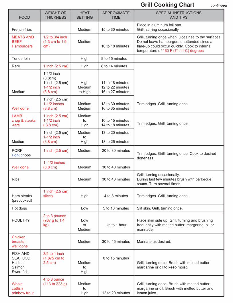
Grill Cooking Chart
FOOD
WEIGHT OR
THICKNESS
HEAT
SETTING
APPROXIMATE
TIME
SPECIAL INSTRUCTIONS
AND TIPS
VEGETABLES
Slice. Dot with butter or margarine. Wrap in
heavy-duty foil. Grill, turning occasionally.
Fresh beets, carrots,
turnips Medium 12 to 20 minutes
Grill, turning once. Brush occasionally with
melted butter or margarine.
Onion
1/2 in (1.3 cm)
slices Medium 8 to 20 minutes
Season with Italian dressing, butter, or
margarine.
Sweet white potatoes
Whole
6 to 8 ounces
(170 to 227 g)
Medium
High
40 to 60 minutes
45 to 60 minutes
Wrap individually in heavy-duty foil. Grill,
rotating occasionally.
Frozen asparagus,
peas, green beans,
sprouts Medium 15 to 30 minutes
Dot with butter or margarine.
Wrap in heavy-duty foil. Grill, turning
occasionally.
30
Grill Cooking Chart continued
FOOD
WEIGHT OR
THICKNESS
HEAT
SETTING
APPROXIMATE
TIME
SPECIAL INSTRUCTIONS
AND TIPS
French fries Medium 15 to 30 minutes
Place in aluminum foil pan.
Grill, stirring occasionally
MEATS AND
BEEF
Hamburgers
1/2 to 3/4 inch
(1.3 cm to 1.9
cm)
Medium
10 to 18 minutes
Grill, turning once when juices rise to the surfaces.
Do not leave hamburgers unattended since a
flare-up could occur quickly. Cook to internal
temperature of 160 F (71.11 C) degrees
Tenderloin High 8 to 15 minutes
Rare 1 inch (2.5 cm) High 8 to 14 minutes
Medium
1-1/2 inch
(3.8cm)
1 inch (2.5 cm)
1-1/2 inch
(3.8 cm)
High
Medium
to High
11 to 18 minutes
12 to 22 minutes
16 to 27 minutes
Well done
1 inch (2.5 cm)
1-1/2 inches
(3.8 cm)
Medium
Medium
18 to 30 minutes
16 to 35 minutes
Trim edges. Grill, turning once
LAMB
chop & steaks
-rare
1 inch (2.5 cm)
1-1/2 inch
( 3.8 cm)
Medium
to
High
10 to 15 minutes
14 to 18 minutes
Medium
1 inch (2.5 cm)
1-1/2 inch
(3.8 cm)
Medium
to
High
13 to 20 minutes
18 to 25 minutes
Trim edges. Grill, turning once.
PORK
Pork chops
1 inch (2.5 cm) Medium 20 to 30 minutes
Well done
1 -1/2 inches
(3.8 cm) Medium 30 to 40 minutes
Trim edges. Grill, turning once. Cook to desired
doneness.
Ribs Medium 30 to 40 minutes
Grill, turning occasionally.
During last few minutes brush with barbecue
sauce. Turn several times.
Ham steaks
(precooked)
1 inch (2.5 cm)
slices High 4 to 8 minutes Trim edges. Grill, turning once.
Hot dogs Low 5 to 10 minutes Slit skin. Grill, turning once.
POULTRY
2 to 3 pounds
(907 g to 1.4
kg)
Low
or
Medium
Up to 1 hour
Place skin side up. Grill, turning and brushing
frequently with melted butter, margarine, oil or
marinade.
Chicken
breasts -
well done
Medium 30 to 45 minutes Marinate as desired.
FISH AND
SEAFOOD
Halibut
Salmon
Swordfish
3/4 to 1 inch
(1.875 cm to
2.5 cm) Medium
to
High
8 to 15 minutes
Grill, turning once. Brush with melted butter,
margarine or oil to keep moist.
Whole
catfish
rainbow trout
4 to 8 ounce
(113 to 223 g) Medium
to
High 12 to 20 minutes
Grill, turning once. Brush with melted butter,
margarine or oil. Brush with melted butter and
lemon juice.

31
Grill Recipe Suggestion
BBQ SALMON
2 large salmon steaks
2 tbs.(30mL) oil
Salt and pepper
2 oz.(57g) thin bacon slices
2 tbs.(30mL ) butter
1 tbs.(15mL) lemon juice
Spring of parsley
Lemon wedges
Preheat the BBQ.
Brush the steaks with oil and season
with salt and pepper. Place on BBQ grill
and cook for 10 minutes, turning steaks
over halfway cooking time.
Meanwhile fry the bacon in a pan on
the side burner. Drain on paper towels.
Meld the butter in a small saucepan
taking care not to discolour it. Arrange
the fish and bacon on serving plates.
Pour the butter over and sprinkle with
lemon juice. Garnish with parsley
springs and lemon wedges. Serve with
boiled potatoes tossed in butter and
sprinkled with chopped parsley and a
crisp lettuce salad.
Note: Substitute catfish, halibut or cod
for salmon.
BAKED CHILI CORN
6 medium ears corn, husked
3 tbs. (45 mL) Butter or margarine, melted
Dash ground cumin
Dash ground coriander
About ½ hour before cooking, turn the
butter on for grill. Place each corn on a
heavy-duty foil. In a bowl, combine
remaining ingredients. Mix well. Brush
1-1/2 tsp. (22.5 mL) Butter mixture over
each ear. Close foil and fold up ends to
seal. Place on grill. Cook, turning
packets occasionally 10 to 12 minutes
or until cooked through.
TANGY SEAFOOD KABOBS1 lb. Large shrimp, shelled & deveined
¾ lbs. sea scallops
2/3 c. chili sauce
¼ c. cider vinegar
butter and sprinkled with chopped
parsley and a crisp lettuce salad.
In medium bowl, combine shrimp and
scallops. In small bowl combine chili
sauce and next six ingredients. Pour
over seafood. Toss to coat.
Cover, refrigerate 2 hours.
3 tbs. (45 mL) (chopped parsley)
1 tbs. (15 mL) vegetable oil
1 tbs. (15 mL) Worcestershire sauce
½ tsp.(7.5 mL) prepared horseradish
1 cove garlic, minced
1 20 oz. (567 g) Can pineapple chunks
in juice, drained half hour before
cooking, turn the burner to the grill on
full. Drain seafood reserving marinade.
On each of twelve 10” skewers, thread
2 shrimps and 2 scallops, alternating
with pineapple chunks. Place skewers
on grill. Cook 7-10 minutes, often
basting and turning.
PORK CHOPS
4 Pork chops
Marinade
1 large onion
2 tbs. (30 mL) lemon juice or vinegar
2 tbs. (30 mL) oil
½ tsp. (7.5 mL) powdered mustard
2 tsp. (30 mL) Worcestershire sauce
½ tsp. (7.5 mL) freshly ground black pepper
1 tsp. (15 mL) sugar
½ tsp. (7.5 mL0 paprika
1 clove garlic
Peel, grate onion, and add rest of the
ingredients except the pork chops. Mix
well. Pour over chops and marinate one
hour in a cool place. Turn the BBQ grill
on full. Heat 10 minutes.
BBQ the chops brushing with the
marinade occasionally. Serve with
mixed salad, dressed with vinaigrette
flavored with fresh dill.
BARBECUED LONDON BROIL4 to 6 servings
¾ c. Italian dressing
1 tsp. (15 mL) Worcestershire sauce
1 tsp. (15 mL) dry mustard
¼ tsp. (3.75 mL) thyme, crushed
1 medium onion, sliced
1 pound flank steak, scored
2 tbs. (15 mL) butter, melted
Combine first 4 ingredients, add onion
and marinade flank steak with it.
Refrigerate at least 4 hours or
overnight. Remove steak and grill on
your preheated BBQ grill. Grill 5 to 7
minutes on each side basting
frequently with the marinade. In the
meantime sauté onions from the
marinade in butter in a skillet on your
side burner for 3 minutes. To serve,
slice steak diagonally into thin slices,
sprinkle onions over top. Garnish with
vegetable kabobs.
BARBECUED POTATOES and CHEESE
1-1/2 cups shredded cheddar cheese
1 can (10-3/4 oz.) condensed cream of mushroom soup
1/3 cup milk
2 tbs.(30 mL) barbecue sauce
¼ tsp.(3.75 mL) oregano
¼ tsp. (3.75 mL) salt
1/8 tsp. (1.875 mL) pepper
4 cups thinly sliced potatoes (4 medium-sized potatoes)
Preheat grill. Combine cheese,
condensed soup, milk, BBQ sauce,
oregano, salt and pepper in a large
mixing bowl. Stir in potatoes until well
coated. Turn into well buttered1-1/2
quart rectangular baking dish. Cover
dish with aluminum foil. Bake covered
25 minutes on medium with the lid of
your BBQ grill closed. Remove foil
and continue baking 15 minutes
longer or until potatoes are tender. Let
stand 5 minutes before serving.
VEGETABLE KABOBS3 medium-sized zucchini
12 cherry tomatoes
12 fresh mushrooms
Grated Parmesan cheese
Parboil whole zucchini 5 minutes on
your side burner or until just tender.
Drain and cut into ½ inch slices.
Thread zucchini, tomatoes and
mushrooms alternately on each of six
skewers. Brush with marinade made
of Italian dressing, Worcestershire
sauce, mustard and thyme. Grill 5 to 7
minutes turning and basting
occasionally. Sprinkle liberally with
Parmesan cheese.

32
Grill Recipe Suggestion continued
FAJITAS1-1/2 lb. flank steak or boned chicken
breasts
2 tbs. oil
½ cup limejuice
½ tsp. (7.5 mL) salt
½ tsp. (7.5 mL) celery salt
¼ tsp. (3.75 mL) garlic powder
½ tsp. (7.5 mL) pepper
¼ tsp. (3.75 mL) oregano
¼ tsp. (3.75 mL) cumin
Flour tortillas lemon
Pound flank steak to ¼ inch thickness
or flatten chicken breasts. Mix oil, lime
juice and seasonings in a zip lock bag.
Add meat and shake bag to coat the
meat. Refrigerate overnight or at least 6
to 8 hours. Wrap tortillas in foil.
Remove meat from marinade. Cook on
a pre-heated gas grill for 5 to 8 minutes
on each side. While meat is cooking,
heat tortillas on grill. Slice meat across
grain in thin slices. Place on hot platter.
Squeeze lemon juice over. Wrap meat
and any of the following toppings in
tortillas: chopped tomatoes, guacamole,
sour cream, taco sauce.
BEEF AND LAMB KABOBSServe 4
½ lb. boneless sirloin or beef cut into 1”
cubes
½ lb. boneless loin of lamb cut into 1”
cubes
2/3 c. water, divided
¼ c. chopped onion
2 tbs. (30 mL) soy sauce
¼ c. vegetable oil, divided
1 tbs. (15 mL) dark brown sugar
1 tbs. (15 mL) fresh lemon juice
2 cloves garlic, minced
¼ tsp. (3.75 mL) ground cumin
¼ tsp. (3.75 mL) ground coriander
¼ tsp. (3.75 mL)ground turmeric
1/8 tsp. (1.25 mL) ground red pepper
1/8 tsp. (1.25 mL) ground ginger
1 red pepper cut into chunks
1 large banana, cut into chunks
8 small mushrooms
1/3 c. smooth peanut butter
In blender, process 1/3 c. water, onion,
soy sauce, 2 tsp. (30 mL) oil and the
next 8 ingredients until smooth. Pour
over meat cubes and marinate about 4
hours, turning occasionally. Drain and
reserve marinade. Onto to four 12”
skewers alternately thread meat,
pepper, banana and mushrooms.
Preheat grill. Brush the kabobs with oil.
Grill 7-8 minutes each side.
Bring marinade to boil on the side
burner in a saucepan. Add remaining
1/3 c. water and peanut butter. Stir to
blend. Heat through. If sauce gets too
thick, add 1 tbs. water. Serve sauce
with kabobs.
EGGPLANT CAVIAR1 large eggplant
2 tbs. (30 mL) olive oil
2 tbs. (30 mL) wine vinegar
2 tbs. (30 mL) finely chopped onion
½ clove garlic, minced
1 medium tomato, chopped salt and
pepper
Roast eggplant on gas grill over
medium flame, turning occasionally
until thoroughly cooked. This may take
30 minutes. Remove from grill and cool
for handling. Strip off the skin and chop
eggplant finely. Add all the seasonings.
Chill thoroughly and serve on toast.
CHICKEN TANDOORI STYLE8 large chicken thighs or drumsticks
1 c. plain nonfat yogurt
½ c. lemon juice
2 tsp. (30 mL) salt
½ tsp. (7.5 mL) cayenne
½ tsp. (7.5 mL) black pepper
½ tsp. (7.5 mL) crushed garlic
½ tsp. (7.5 mL) grated ginger
1 tbs. corn oil
Combine all the ingredients in a large
mixing bowl and marinate the chicken
for 8 hours in the refrigerator. Drain the
chicken and spread on the spit running
the rod on the fleshier side of the bone.
Rotis using the rotisserie burner. Cook
on medium high heat for 40 minutes
basting occasionally with the remainder
of the marinade mixture. Serve with
sliced onions and lemon wedges.
SPARE RIBSMarinade:
1 c. soy sauce
½ c. honey
½ c. vinegar
½ c. dry sherry
2 tsp. (30 mL) chopped garlic
2 tsp. (30 mL) sugar
1 c. water
1 chicken bouillon cube
1 can beer for basting sauce
Marinade ribs for 3 hours. Use
marinade for basting by adding beer
to it. Place pan under the ribs and
baste frequently. To cook ribs select
lean, meaty ribs and accordion pleat
them with your spit. Slide four prong
meat hook down the length of spit and
tighten. At the beginning of
the rack and to its center, penetrate
the second rib with the pointed end of
the spit and push it between the meat.
Skip a couple and continue the
process until the entire rack is
accordion pleated. Fasten the second
meat hook into the rack. Turn your
rotisserie burner on high. Rotis for 50
minutes or until done.
PORK ROASTApple cider vinegar basting sauce:
1 c. apple cider vinegar
6 oz. (170 g) water
½ stick butter
Salt, pepper, parsley and garlic
seasoning
2 oz. (57 g) lemon juice
10 lbs. pork roast
Time: 1-1/2 hours to 2 hours
Bring pork to room temperature before
placing it on the spit rod. Place on the
rod and test for balance. Light rotis
burner. Turn control knob to high. Use
the above basting sauce for rotissing.
TURKEY12 lb. turkey
Beer basting sauce:
1 can beer
12 oz. (340 g) water
1 stick butter
1 tsp. (15 mL) salt
1 tsp. (15 mL) pepper
½ tsp. (7.5 mL) garlic flakes
1 tsp. (15 mL) parsley
Thaw the bird completely. Wash
inside out. Securely tie the legs and
wings. Light rotisserie burner. Turn to
high. Combine all the ingredients for
basting sauce in a shallow pan. Place
it under the turkey 15 to 20 minutes.
Cook for approximately 3 hours. The
basting sauce combined with turkey
drippings makes a delicious gravy.

33
LIMITED WARRANTY (Model # 720-0778B)The manufacturer warrants to the original consumer-purchaser only that this product (Model #720-0778B) shall be free from defects in
workmanship and materials after correct assembly and under normal and reasonable home use for the periods indicated below beginning on the
date of purchase. The manufacturer reserves the right to require photographic evidence of damage, or that defective parts be returned, postage
and/or freight pre-paid by the consumer, for review and examination.
• TUBE BURNERS: 5 year LIMITED warranty against perforation.
• COOKING GRIDS and FLAME TAMERS: 1 year LIMITED warranty; does not cover dropping, chipping, scratching, or surface damage.
• STAINLESS STEEL PARTS: 1 year LIMITED warranty against perforation; does not cover cosmetic issues like surface corrosion, scratches and
rust.
• ALL OTHER PARTS: 1 year LIMITED warranty (Includes, but not limited to, valves, frame, housing, cart, control panel, igniter, regulator, hoses)
*Does not cover chipping, scratching, cracking surface corrosion, scratches or rust.
Upon consumer supplying proof of purchase as provided herein, Manufacturer will repair or replace the parts which are proven defective during the
applicable warranty period. Parts required to complete such repair or replacement shall be free of charge to you except for shipping costs, as long
as the purchaser is within the warranty period from the original date of purchase. The original consumer-purchaser will be responsible for all
shipping charges of parts replaced under the terms of this limited warranty. This limited warranty is applicable in the United States and Canada
only, is only available to the original owner of the product and is not transferable. Manufacturer requires reasonable proof of your date of purchase.
Therefore, you should retain your sales receipt and/or invoice. If the unit was received as a gift, please ask the gift-giver to send in the receipt on
your behalf, to the below address. Defective or missing parts subject to this limited warranty will not be replaced without registration or proof of
purchase. This limited warranty applies to the functionality of the product ONLY and does not cover cosmetic issues such as scratches, dents,
corrosions or discolouring by heat, abrasive and chemical cleaners or any tools used in the assembly or installation of the appliance, surface rust,
or the discolouration of stainless steel surfaces. Surface rust, corrosion, or powder paint chipping on metal parts that does not affect the structural
integrity of the product is not considered a defect in workmanship or material and is not covered by this warranty. This limited warranty will not
reimburse you for the cost of any inconvenience, food, personal injury or property damage. If an original replacement part is not available, a
comparable replacement part will be sent. You will be responsible for all shipping charges of parts replaced under the terms of this limited warranty.
MANUFACTURER WILL NOT PAY FOR:
•Service calls to your home.
•Repairs when your product is used for other than normal, single-family household or residential use.
•Damage resulting from accident, alteration, misuse, lack of maintenance/cleaning, abuse, fire, flood, acts of God, improper installation, and
installation not in accordance with electrical or plumbing codes or misuse of product..
•Any food loss due to product failures.
•Replacement parts or repair labour costs for units operated outside the United States or Canada.
•Pickup and delivery of your product.
•Postage fees or photo processing fees for photos sent in as documentation.
•Repairs to parts or systems resulting from unauthorized modifications made to the product.
•The removal and/or reinstallation of your product.
•Shipping cost, standard or expedited, for warranty/non-warranty and replacement parts.
DISCLAIMER OF IMPLIED WARRANTIES; LIMITATION OF REMEDIES
Repair or replacement of defective parts is your exclusive remedy under the terms of this limited warranty. Manufacturer will not be responsible for
any consequential or incidental damages arising from the breach of either this limited warranty or any applicable implied warranty, or for failure or
damage resulting from acts of God, improper care and maintenance, grease fire, accident, alteration, replacement of parts by anyone other than
manufacturer, misuse, transportation, commercial use, abuse, hostile environments (inclement weather, acts of nature, animal tampering), improper
installation or installation not in accordance with local codes or printed manufacturer instructions.
THIS LIMITED WARRANTY IS THE SOLE EXPRESS WARRANTY GIVEN BY THE MANUFACTURER. NO PRODUCT PERFORMANCE
SPECIFICATION OR DESCRIPTION WHEREVER APPEARING IS WARRANTED BY MANUFACTURER EXCEPT TO THE EXTENT SET FORTH
IN THIS LIMITED WARRANTY. ANY IMPLIED WARRANTY PROTECTION ARISING UNDER THE LAWS OF ANY STATE, INCLUDING IMPLIED
WARRANTY OF MERCHANTABILITY OR FITNESS FOR A PARTICULAR PURPOSE OR USE, IS HEREBY LIMITED IN DURATION TO THE
DURATION OF THIS LIMITED WARRANTY.
Neither dealers nor the retail establishment selling this product has any authority to make any additional warranties or to promise remedies in
addition to or inconsistent with those stated above. Manufacturer's maximum liability, in any event, shall not exceed the documented purchase price
of the product paid by the original consumer. This warranty only applies to units purchased from an authorized retailer and or re-seller. NOTE:
Some states do not allow an exclusion or limitation of incidental or consequential damages, so some of the above limitations or exclusions may not
apply to you; this limited warranty gives you specific legal rights as set for herein. You may also have other rights which vary from province to
province.
If you wish to obtain performance of any obligation under this limited warranty, you should write to:
Nexgrill Customer Relations5270 Edison Avenue,
Chino, CA 91710All consumer returns, parts orders, general questions, and troubleshooting
assistance can be acquired by calling Canada: 800-648-5864, U.S./Mexico: 800-913-8999

34
Natural Gas Conversion for Model# 720-0778B
NG Conversion Kit for Model # 720-0778B
WARNING! FALURE TO HEED THESE WARNINGS COULD RESULT IN A FIRE OR EXPLOSION THAT COULD CAUSE SERIOUS BODILY INJURY, DEATH OR PROPERTY DAMAGE.
Installation of this Natural Gas Conversion kit must be performed by a QUALIFIED GAS TECHNICIAN ONLY.
DO NOT ATTEMPT TO INSTALL THIS KIT YOURSELF. Improper installation could result in a gas leak which
could cause a fire or explosion and cause serious bodily injury, death or property damage. Leaks due to improper
installation could occur immediately or slowly over time. If you hear any unusual noises or leaks, smell gas or
unusual odours, or notice anything unusual with the operation of your gas appliance after the installation,
immediately shut off the gas supply and discontinue use until the appliance is repaired by a QUALIFIED GAS
TECHNICIAN.
If there are damaged or missing parts when you unpack this kit, call Canada: 800-648-5864, U.S./Mexico: 800-
913-8999
DO NOT have your QUALIFIED GAS TECHNICIAN attempt to install this kit until you receive replacement for any
damaged or missing parts.
Orifice Chart
The different burner valves in this grill have different BTU ratings. This means that the amount of gas coming
from each orifice varies in order to create the BTUs. The holes in the orifices themselves are drilled to different
sizes so as to allow the proper amount of gas to flow through them. Please note the chart below as an easy
reference for the various orifice opening sizes for the different valves in the grill.
720-0778B, 730-0778B orifice size
Liquid Propane (LP) Natural Gas (NG)
Components Orifice Size BTU Orifice Size BTU
Main Burner 1.02 mm 12,000 1.70 mm 12,000
Searing Side
Burner 1.15 mm 15,000 1.90 mm 15,000
Rear Burner 1.07 mm 13,000 1.84 mm 13,000
Below are the tools included in the package:
Hex Key
6 mm Nut Driver
6 mm Wrench

35
Natural Gas Conversion for Model# 720-0778B
Warning: Make sure all grill components are completely cool and gas supply is turned off and removed from grill
prior to performing the conversion.
NG Hose and Regulator ConversionTools required:
14 mm wrench
Phillips Head Screwdriver (+)
1. Turn all knobs to OFF. Turn off LP (Liquid Propane) gas supply and remove the LP (Liquid Propane)
cylinder from the grill cart. Remove the brass adapter of the LP regulator from the manifold with a wrench.
2. Install the NG (Natural Gas) regulator hose to the manifold and secure using a wrench. Tighten the NG
regulator on the side panel with two 5/32*10 mm screws that pre-assemble on the NG regulator.

36
Natural Gas Conversion for Model# 720-0778B
Main Tube Burner ConversionTools required:
Phillips Head Screwdriver (+)
6 mm Nut Driver
Steps
1. Remove the warming rack, cooking grids, and flame tamers.
2. Remove the main tube burners by removing the pin securing the burners near the back wall of the firebox
and the screw near the front of the firebox that secures the igniter bracket to the burner. Gently lift the tube
burners up and out.
3. Remove LP (Liquid Propane) orifice with 6 mm nut driver for each of the main burners, and replace with NG
orifice by hand (4 main burner).
4. Replace the tube burners and screw back into original position.
Nipper pliers

37
Natural Gas Conversion for Model# 720-0778B
Searing Side Burner ConversionTools required:
Phillips Head Screwdriver (+)
6 mm Nut Driver
The step-by-step instructions for converting the searing side burner’s orifice are below.1. Remove the screw under C bracket to take off the C bracket, then remove 4 screws at each corner of the
searing side burner and one screw for igniter.
2. Remove the searing side burner LP (Liquid Propane) orifice with the 6 mm driver, then Replace the NG
(Natural Gas) orifice to the connector by hand from beneath of side burner, then replace the side burner
to the original position, tighten screws for all corners.

38
Natural Gas Conversion for Model# 720-0778B
Rear Burner Conversion
Tools required:
Steps
1. Remove the two screws securing the rotisserie heat shield from inside the firebox. Remove three securing
screws and drop off the Rear Baffle from the back of the grill.
2. Remove the (Liquid Propane) orifice with 6 mm wrench.
3. Replace the NG orifice with 6 mm wrench. Then put rear baffle and screw back into the original position.
6 mm Wrench
Phillips Head Screwdriver (+)

39
Natural Gas Conversion for Item# /Model# 720-0778B
For Main Tube Burner Conversion Only(The 3 steps below are not necessary for the Sear side burner and Rear burner )
You will need to adjust the High Flame setting screw when converting the barbecue from Propane to Natural Gas.
Please follow the steps as detailed below.
1. Remove each Control Knob of main tube burners and sear side burner by loosening the socket head grub
screw with the Allen key.
2. Use a screw driver to turn the High Flame Set Screw clockwise approximately 90 degree.
3. Check that burner operates at the new high fire setting - it may be necessary to adjust the screw setting
slightly to get the ideal burner flame height.
Warning!! Gas Valves are preset at the factory to operate on LP gas or NG gas. If you wish to convert, be sure to
consult your gas supplier or trained technician for the conversion.
A. After the Natural Gas regulator has been installed, attach the PVC Gas hose to the regulator (see drawing
below).
B. Connect the other end of the PVC Gas Hose to the house gas line using the quick-connect fitting. To use
the quick-connect fitting, lift the head of the connector back. Insert the end of the PVC hose and release the
head of the connector. Ensure connection is secure.
There is a brass adapter for natural gas lines that are pre-regulated. If the gas line is not pre-regulated, remove
the brass adapter and connect the regulator directly to the PVC gas hose.
Once conversion is complete, please attach the NG CSA certification sticker to the grill.If you should have any questions regarding natural gas conversion, please contact customer service at
Canada: 800-648-5864, U.S./Mexico: 800-913-8999
.

40
Natural Gas Conversion for Model# 720-0778B
WARNING: IMPORTANT!BEFORE LIGHTING…Inspect the gas supply hose prior to turning the gas
“ON.” If there is evidence of cuts, wear, or abrasion,
it must be replaced prior to use. Do not use the grill
if the odour of gas is present. Only the pressure
regulator and hose assembly supplied with the unit
should be used.
Never substitute regulators and hose assembly for
those supplied with the grill. If a replacement is
necessary, contact the manufacturer for proper
replacement. The replacement must be that
specified in the manual.
WARNING: Always keep your face and body as
far away from the burner as possible when
lighting.
TO LIGHT THE MAIN BURNER
Make sure all knobs are “OFF” then turn on the gas.
Always keep your face and body as far from the grill
as possible when lighting.
Your grill has an exclusive patented built-in ignition.
The igniter is built into the valve. To ignite each
burner simply push and turn the control knobs to the
HI setting, you will hear the valve click as it sends a
spark to the pilot flame. If the burner does not light
wait 5 minutes for any excess gas to dissipate and
then retry.
TO LIGHT THE SEARING SIDE BURNER
To light the searing side burner, remove any cooking
utensils from the burner grate. Push and turn the control
knob counterclockwise to the “IGNITE/ON” position. If the
burner does not light, turn the control knob to “OFF.” If the
smell of gas is detected and the igniter is not functioning,
immediately turn the control knob “OFF.” Allow 5 minutes
for any accumulated gas to dissipate. If the side burner
igniter is not functioning, see the following section for
match lighting.
TO MATCH LIGHT THE GRILL
If the burner will not light after several attempts then the
burner can be match lit.
Match light extension rod is located on the inside panel of
the door.
If you’ve just attempted to light the burner with the igniter,
allow 5 minutes for any accumulated gas to dissipate.
Keep your face and hands as far away from the grill as
possible.
Insert a lit match attached to the lighting rod through the
cooking grids to the burner.
Press the control knob and rotate left to the HI/ON setting
continue to press the knob until the burner ignites.
Burner should light immediately.
If the burner does not light in 4 seconds turn the knob off,
wait 5 minutes and try again.
TO MATCH LIGHT THE SIDE BURNER
Hold a lit extended match near the side burner ports, turn
the control knob counterclockwise to “IGNITE/HI.” Move
your hand immediately once the burner is lit. Rotate the
control knob to the desired setting.
Do not attempt to light the grill if odour of gas is present. Call for service Canada: 800-648-5864,
U.S./Mexico: 800-913-8999
FLAME CHARACTERISTICS
Check for proper burner flame characteristics.
Burner flames should be blue and stable with no yellow
tips, excessive noise, or lifting. If any of these conditions
exist call our customer service line. If the flame is yellow,
it indicates insufficient air. If the flame is noisy and tends
to lift away from the burner, it indicates too much air.
Each burner is adjusted prior to shipment; however, variations in the local gas supply may make minor adjustments necessary.
Visually check the burner flames prior to each
use, the flames should look like this picture, if
they do not, refer to the burner maintenance
part of this manual.

41
Natural Gas Conversion for Model# 720-0778B
Note: Remove all packaging, including straps, before using the grill
Main Burners
Rear Burner
IGNITE / HI
LO
OFF
IGNITE / H I
LO
IGNITE / HI
LO
OFF
1
3
2
IG NITE / H I
LO
IG NITE / ON
OFF OFFOFF
OFF
IGNITE / H I
LO
IG NITE / HI
LO
OFF
Sear Burner
Make sure the lid is open.
Push and turn Main Burner knob slowly to
IGNITE/HIGH. Keep knob pressed in until the burner is
lit.
If burner does not light within 5 seconds, turn the knob
to OFF and repeat the lighting instruction.
If burner does not light up after step 3, turn the knob to
OFF, wait 5 minutes, and repeat the lighting procedure
or light by match.
1
2
3
4
IGNITE / ON
1
2
OFF Make sure the lid is open.
Push and slowly turn the Rear Burner knob to IGNITE/ON
position. Keep knob pressed in until the burner is lit. Once it
is lit, continue to press and hold for another 15 seconds to
ensure the burner stays lit.
If burner does not light within 5 seconds, turn the knob to
OFF position and repeat the lighting procedure.
If burner fails to light after step 3, turn the knob to OFF
position, wait 5 minutes, then repeat the lighting procedure
or light by match.
1
2
3
4

42
Natural Gas Conversion for Model# 720-0778B
1. If the burner will not light after several attempts them the burner can be match lit, before using the match
allow 5 minutes for any accumulated gas to dissipate.
2. Clip a paper match on one end of the lighting rod.
3. Light match.
4. Hold lighting rod and insert lighted match right next to the burner ports or ceramic file.
5. Push and turn the designated control knob to IGNITE/HIGH.
6. Burner should ignite immediately.
Match light
Main burner
Rear burner/Sear burner