Outdoor Cellular Sub-6 5G Antenna - linxtechnologies.com
18
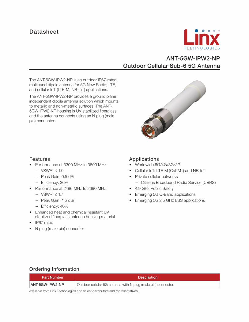
Datasheet Features • Performance at 3300 MHz to 3800 MHz ― VSWR: ≤ 1.9 ― Peak Gain: 0.5 dBi ― Efficiency: 36% • Performance at 2496 MHz to 2690 MHz ― VSWR: ≤ 1.7 ― Peak Gain: 1.5 dBi ― Efficiency: 40% • Enhanced heat and chemical resistant UV stabilized fiberglass antenna housing material • IP67 rated • N plug (male pin) connector The ANT-5GW-IPW2-NP is an outdoor IP67-rated multiband dipole antenna for 5G New Radio, LTE, and cellular IoT (LTE-M, NB-IoT) applications. The ANT-5GW-IPW2-NP provides a ground plane independent dipole antenna solution which mounts to metallic and non-metallic surfaces. The ANT- 5GW-IPW2-NP housing is UV stabilized fiberglass and the antenna connects using an N plug (male pin) connector. Applications • Worldwide 5G/4G/3G/2G • Cellular IoT: LTE-M (Cat-M1) and NB-IoT • Private cellular networks ― Citizens Broadband Radio Service (CBRS) • 4.9 GHz Public Safety • Emerging 5G C-Band applications • Emerging 5G 2.5 GHz EBS applications ANT-5GW-IPW2-NP Outdoor Cellular Sub-6 5G Antenna Ordering Information Part Number Description ANT-5GW-IPW2-NP Outdoor cellular 5G antenna with N plug (male pin) connector Available from Linx Technologies and select distributors and representatives.
Transcript of Outdoor Cellular Sub-6 5G Antenna - linxtechnologies.com
Datasheet
Features• Performance at 3300 MHz to 3800 MHz
― VSWR: ≤ 1.9 ― Peak Gain: 0.5 dBi ― Efficiency: 36%
• Performance at 2496 MHz to 2690 MHz ― VSWR: ≤ 1.7 ― Peak Gain: 1.5 dBi ― Efficiency: 40%
• Enhanced heat and chemical resistant UV stabilized fiberglass antenna housing material
• IP67 rated• N plug (male pin) connector
The ANT-5GW-IPW2-NP is an outdoor IP67-rated multiband dipole antenna for 5G New Radio, LTE, and cellular IoT (LTE-M, NB-IoT) applications.
The ANT-5GW-IPW2-NP provides a ground plane independent dipole antenna solution which mounts to metallic and non-metallic surfaces. The ANT-5GW-IPW2-NP housing is UV stabilized fiberglass and the antenna connects using an N plug (male pin) connector.
Applications• Worldwide 5G/4G/3G/2G• Cellular IoT: LTE-M (Cat-M1) and NB-IoT• Private cellular networks
― Citizens Broadband Radio Service (CBRS)• 4.9 GHz Public Safety• Emerging 5G C-Band applications• Emerging 5G 2.5 GHz EBS applications
ANT-5GW-IPW2-NPOutdoor Cellular Sub-6 5G Antenna
Ordering Information
Part Number Description
ANT-5GW-IPW2-NP Outdoor cellular 5G antenna with N plug (male pin) connector
Available from Linx Technologies and select distributors and representatives.
2
DatasheetANT-5GW-IPW2-NP
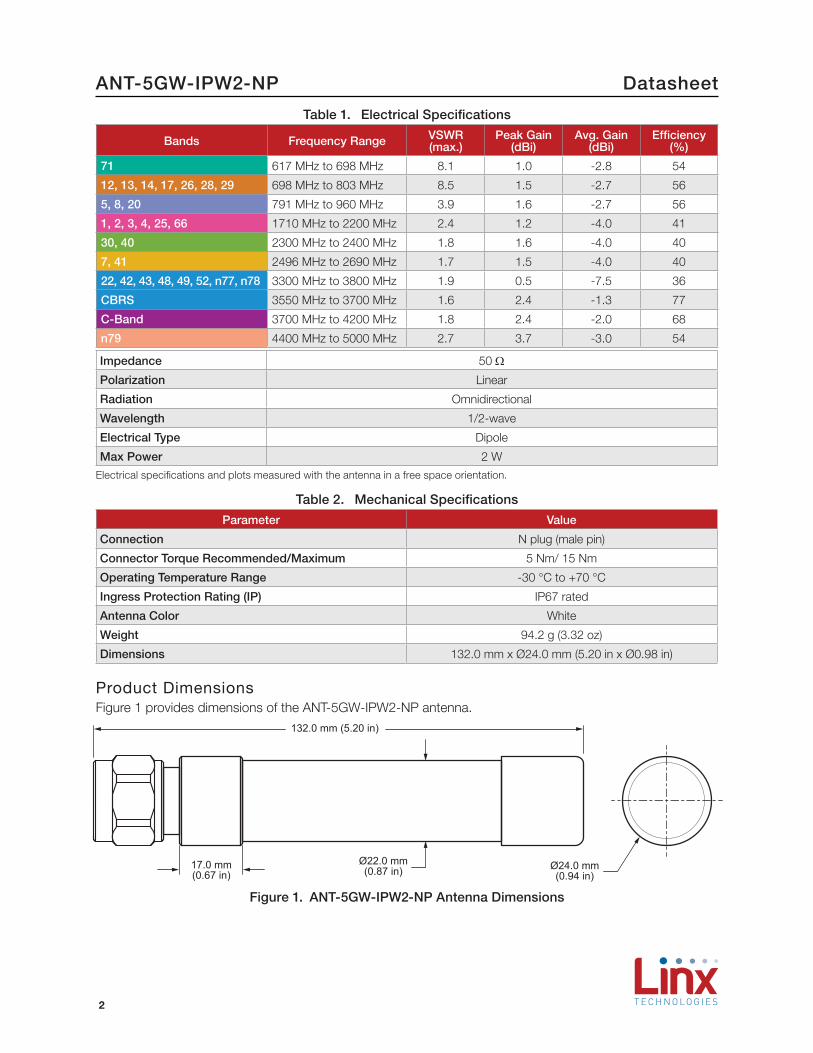
Product DimensionsFigure 1 provides dimensions of the ANT-5GW-IPW2-NP antenna.
132.0 mm (5.20 in)
Ø22.0 mm(0.87 in)17.0 mm
(0.67 in)Ø24.0 mm(0.94 in)
Figure 1. ANT-5GW-IPW2-NP Antenna Dimensions
Table 1. Electrical Specifications
Bands Frequency Range VSWR (max.)
Peak Gain (dBi)
Avg. Gain (dBi)
Efficiency (%)
71 617 MHz to 698 MHz 8.1 1.0 -2.8 54
12, 13, 14, 17, 26, 28, 29 698 MHz to 803 MHz 8.5 1.5 -2.7 56
5, 8, 20 791 MHz to 960 MHz 3.9 1.6 -2.7 56
1, 2, 3, 4, 25, 66 1710 MHz to 2200 MHz 2.4 1.2 -4.0 41
30, 40 2300 MHz to 2400 MHz 1.8 1.6 -4.0 40
7, 41 2496 MHz to 2690 MHz 1.7 1.5 -4.0 40
22, 42, 43, 48, 49, 52, n77, n78 3300 MHz to 3800 MHz 1.9 0.5 -7.5 36
CBRS 3550 MHz to 3700 MHz 1.6 2.4 -1.3 77
C-Band 3700 MHz to 4200 MHz 1.8 2.4 -2.0 68
n79 4400 MHz to 5000 MHz 2.7 3.7 -3.0 54
Impedance 50 Ω
Polarization Linear
Radiation Omnidirectional
Wavelength 1/2-wave
Electrical Type Dipole
Max Power 2 W
Electrical specifications and plots measured with the antenna in a free space orientation.
Table 2. Mechanical Specifications
Parameter Value
Connection N plug (male pin)
Connector Torque Recommended/Maximum 5 Nm/ 15 Nm
Operating Temperature Range -30 °C to +70 °C
Ingress Protection Rating (IP) IP67 rated
Antenna Color White
Weight 94.2 g (3.32 oz)
Dimensions 132.0 mm x Ø24.0 mm (5.20 in x Ø0.98 in)
3
Datasheet ANT-5GW-IPW2-NP
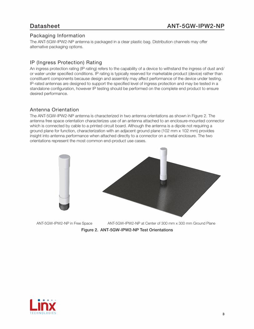
Antenna OrientationThe ANT-5GW-IPW2-NP antenna is characterized in two antenna orientations as shown in Figure 2. The antenna free space orientation characterizes use of an antenna attached to an enclosure-mounted connector which is connected by cable to a printed circuit board. Although the antenna is a dipole not requiring a ground plane for function, characterization with an adjacent ground plane (102 mm x 102 mm) provides insight into antenna performance when attached directly to a connector on a metal enclosure. The two orientations represent the most common end-product use cases.
ANT-5GW-IPW2-NP in Free Space ANT-5GW-IPW2-NP at Center of 300 mm x 300 mm Ground Plane
Figure 2. ANT-5GW-IPW2-NP Test Orientations
IP (Ingress Protection) RatingAn ingress protection rating (IP rating) refers to the capability of a device to withstand the ingress of dust and/or water under specified conditions. IP rating is typically reserved for marketable product (device) rather than constituent components because design and assembly may affect performance of the device under testing. IP-rated antennas are designed to support the specified level of ingress protection and may be tested in a standalone configuration, however IP testing should be performed on the complete end product to ensure desired performance.
Packaging InformationThe ANT-5GW-IPW2-NP antenna is packaged in a clear plastic bag. Distribution channels may offer alternative packaging options.
4
DatasheetANT-5GW-IPW2-NP
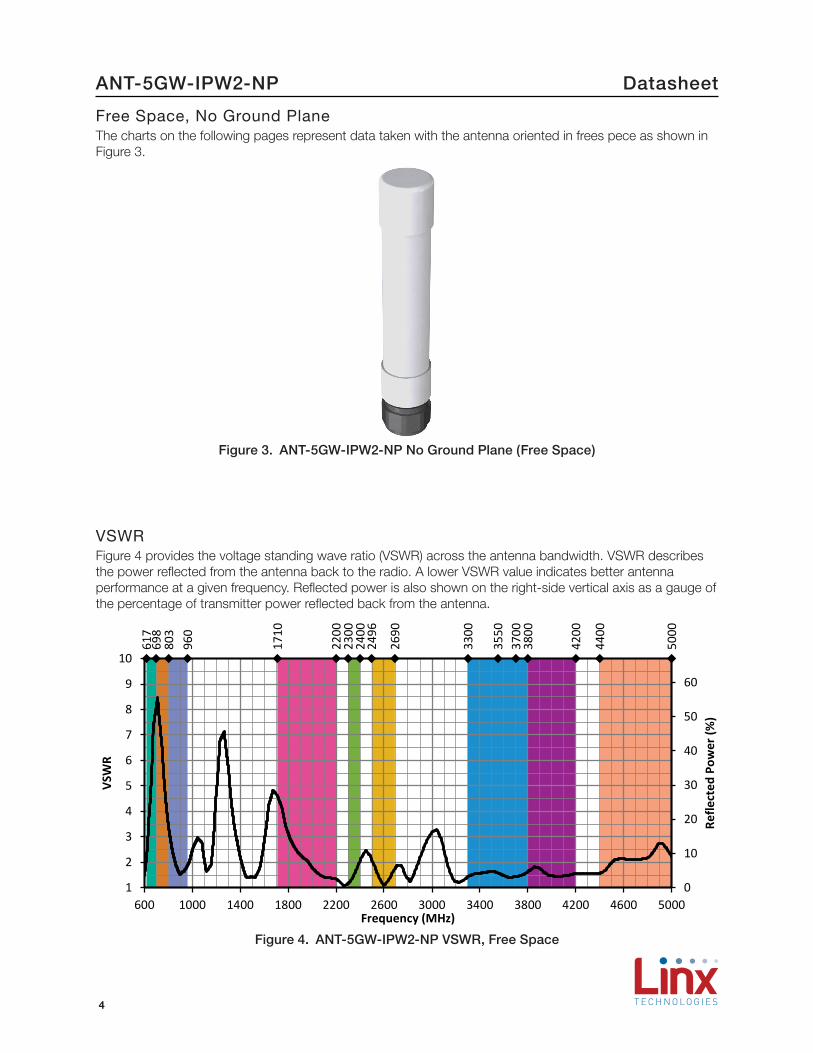
Free Space, No Ground PlaneThe charts on the following pages represent data taken with the antenna oriented in frees pece as shown in Figure 3.
Figure 3. ANT-5GW-IPW2-NP No Ground Plane (Free Space)
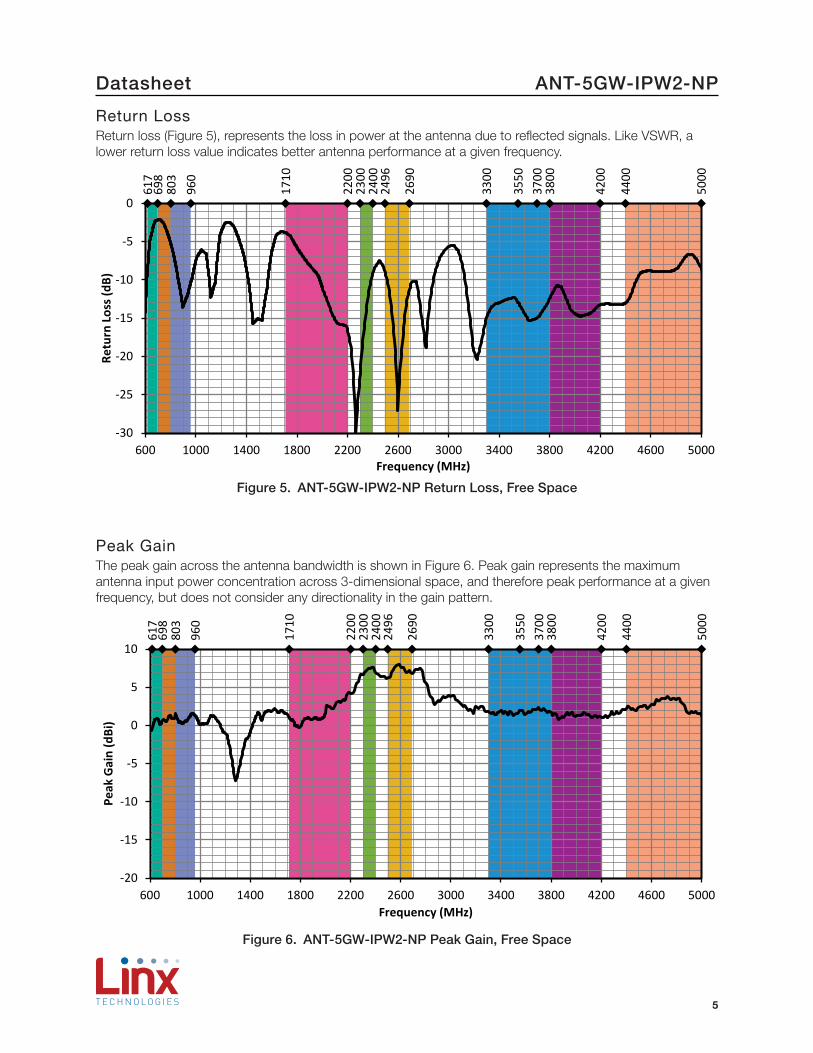
VSWRFigure 4 provides the voltage standing wave ratio (VSWR) across the antenna bandwidth. VSWR describes the power reflected from the antenna back to the radio. A lower VSWR value indicates better antenna performance at a given frequency. Reflected power is also shown on the right-side vertical axis as a gauge of the percentage of transmitter power reflected back from the antenna.
617
698
803
960
1710
2200
2300
2400
2496
2690
3300
3550
3700
3800
4200
4400
5000
0
10
20
30
40
50
60
1
2
3
4
5
6
7
8
9
10
600 1000 1400 1800 2200 2600 3000 3400 3800 4200 4600 5000
Refle
cted
Pow
er (%
)
VSW
R
Frequency (MHz)
Figure 4. ANT-5GW-IPW2-NP VSWR, Free Space
5
Datasheet ANT-5GW-IPW2-NP
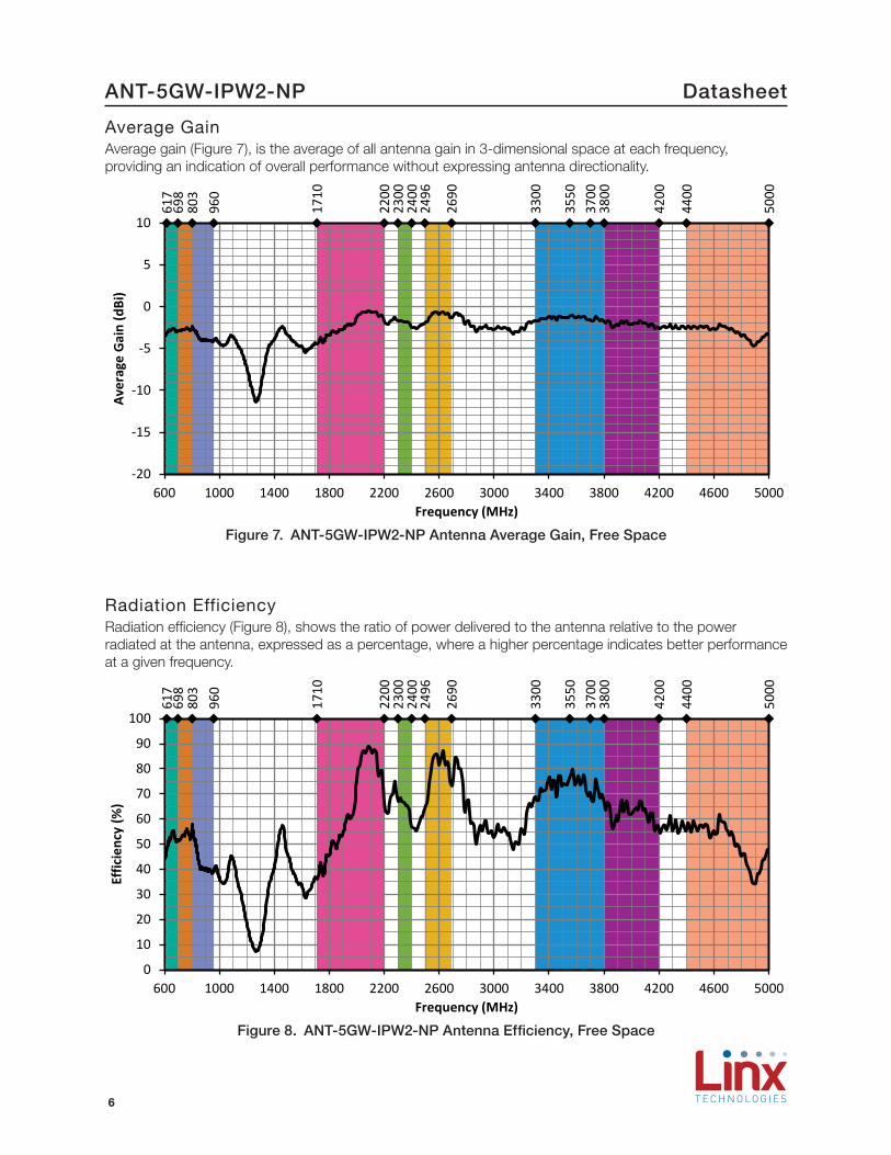
Return LossReturn loss (Figure 5), represents the loss in power at the antenna due to reflected signals. Like VSWR, a lower return loss value indicates better antenna performance at a given frequency.
617
698
803
960
1710
2200
2300
2400
2496
2690
3300
3550
3700
3800
4200
4400
5000
-30
-25
-20
-15
-10
-5
0
600 1000 1400 1800 2200 2600 3000 3400 3800 4200 4600 5000
Retu
rn L
oss (
dB)
Frequency (MHz)
Figure 5. ANT-5GW-IPW2-NP Return Loss, Free Space
Peak GainThe peak gain across the antenna bandwidth is shown in Figure 6. Peak gain represents the maximum antenna input power concentration across 3-dimensional space, and therefore peak performance at a given frequency, but does not consider any directionality in the gain pattern.
617
698
803
960
1710
2200
2300
2400
2496
2690
3300
3550
3700
3800
4200
4400
5000
-20
-15
-10
-5
0
5
10
600 1000 1400 1800 2200 2600 3000 3400 3800 4200 4600 5000
Peak
Gai
n (d
Bi)
Frequency (MHz)
Figure 6. ANT-5GW-IPW2-NP Peak Gain, Free Space
6
DatasheetANT-5GW-IPW2-NP
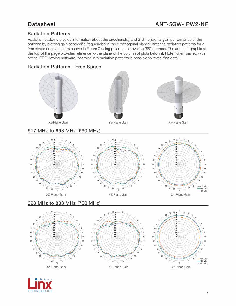
Average GainAverage gain (Figure 7), is the average of all antenna gain in 3-dimensional space at each frequency, providing an indication of overall performance without expressing antenna directionality.
617
698
803
960
1710
2200
2300
2400
2496
2690
3300
3550
3700
3800
4200
4400
5000
-20
-15
-10
-5
0
5
10
600 1000 1400 1800 2200 2600 3000 3400 3800 4200 4600 5000
Aver
age
Gai
n (d
Bi)
Frequency (MHz)
Figure 7. ANT-5GW-IPW2-NP Antenna Average Gain, Free Space
Radiation EfficiencyRadiation efficiency (Figure 8), shows the ratio of power delivered to the antenna relative to the power radiated at the antenna, expressed as a percentage, where a higher percentage indicates better performance at a given frequency.
617
698
803
960
1710
2200
2300
2400
2496
2690
3300
3550
3700
3800
4200
4400
5000
0
10
20
30
40
50
60
70
80
90
100
600 1000 1400 1800 2200 2600 3000 3400 3800 4200 4600 5000
Effic
ienc
y (%
)
Frequency (MHz)
Figure 8. ANT-5GW-IPW2-NP Antenna Efficiency, Free Space
7
Datasheet ANT-5GW-IPW2-NP
Radiation PatternsRadiation patterns provide information about the directionality and 3-dimensional gain performance of the antenna by plotting gain at specific frequencies in three orthogonal planes. Antenna radiation patterns for a free space orientation are shown in Figure 9 using polar plots covering 360 degrees. The antenna graphic at the top of the page provides reference to the plane of the column of plots below it. Note: when viewed with typical PDF viewing software, zooming into radiation patterns is possible to reveal fine detail.
Radiation Patterns - Free Space
XZ-Plane Gain YZ-Plane Gain XY-Plane Gain
617 MHz to 698 MHz (660 MHz)
-50-45-40-35-30-25-20-15-10
-505
12 3
45
6
7
8
9
10
11
12
13
14
1516
171819
202122
23
24
25
26
27
28
29
30
31
32
3334
35 36
-50-45-40-35-30-25-20-15-10
-505
12 3
45
6
7
8
9
10
11
12
13
14
1516
171819
202122
23
24
25
26
27
28
29
30
31
32
3334
35 36
615 MHz655 MHz700 MHz
-50-45-40-35-30-25-20-15-10
-505
12 3
45
6
7
8
9
10
11
12
13
14
1516
171819
202122
23
24
25
26
27
28
29
30
31
32
3334
35 36
XZ-Plane Gain YZ-Plane Gain XY-Plane Gain
698 MHz to 803 MHz (750 MHz)
-50-45-40-35-30-25-20-15-10
-505
12 3
45
6
7
8
9
10
11
12
13
14
1516
171819
202122
23
24
25
26
27
28
29
30
31
32
3334
35 36
-50-45-40-35-30-25-20-15-10
-505
12 3
45
6
7
8
9
10
11
12
13
14
1516
171819
202122
23
24
25
26
27
28
29
30
31
32
3334
35 36
695 MHz750 MHz803 MHz
-50-45-40-35-30-25-20-15-10
-505
12 3
45
6
7
8
9
10
11
12
13
14
1516
171819
202122
23
24
25
26
27
28
29
30
31
32
3334
35 36
XZ-Plane Gain YZ-Plane Gain XY-Plane Gain

8
DatasheetANT-5GW-IPW2-NP
2300 MHz to 2400 MHz (2350 MHz)
-50-45-40-35-30-25-20-15-10
-505
12 3
45
6
7
8
9
10
11
12
13
14
1516
171819
202122
23
24
25
26
27
28
29
30
31
32
3334
35 36
-50-45-40-35-30-25-20-15-10
-505
12 3
45
6
7
8
9
10
11
12
13
14
1516
171819
202122
23
24
25
26
27
28
29
30
31
32
3334
35 36
2300 MHz2350 MHz2400 MHz
-50-45-40-35-30-25-20-15-10
-505
12 3
45
6
7
8
9
10
11
12
13
14
1516
171819
202122
23
24
25
26
27
28
29
30
31
32
3334
35 36
XZ-Plane Gain YZ-Plane Gain XY-Plane Gain
Radiation Patterns - Free Space
791 MHz to 960 MHz (870 MHz)
-50-45-40-35-30-25-20-15-10
-505
12 3
45
6
7
8
9
10
11
12
13
14
1516
171819
202122
23
24
25
26
27
28
29
30
31
32
3334
35 36
-50-45-40-35-30-25-20-15-10
-505
12 3
45
6
7
8
9
10
11
12
13
14
1516
171819
202122
23
24
25
26
27
28
29
30
31
32
3334
35 36
790 MHz875 MHz960 MHz
-50-45-40-35-30-25-20-15-10
-505
12 3
45
6
7
8
9
10
11
12
13
14
1516
171819
202122
23
24
25
26
27
28
29
30
31
32
3334
35 36
XZ-Plane Gain YZ-Plane Gain XY-Plane Gain
1710 MHz to 2200 MHz (1950 MHz)
-50-45-40-35-30-25-20-15-10
-505
12 3
45
6
7
8
9
10
11
12
13
14
1516
171819
202122
23
24
25
26
27
28
29
30
31
32
3334
35 36
-50-45-40-35-30-25-20-15-10
-505
12 3
45
6
7
8
9
10
11
12
13
14
1516
171819
202122
23
24
25
26
27
28
29
30
31
32
3334
35 36
1710 MHz1955 MHz2200 MHz
-50-45-40-35-30-25-20-15-10
-505
12 3
45
6
7
8
9
10
11
12
13
14
1516
171819
202122
23
24
25
26
27
28
29
30
31
32
3334
35 36
XZ-Plane Gain YZ-Plane Gain XY-Plane Gain
9
Datasheet ANT-5GW-IPW2-NP
3300 MHz to 3800 MHz (3550 MHz)
-50-45-40-35-30-25-20-15-10
-505
12 3
45
6
7
8
9
10
11
12
13
14
1516
171819
202122
23
24
25
26
27
28
29
30
31
32
3334
35 36
-50-45-40-35-30-25-20-15-10
-505
12 3
45
6
7
8
9
10
11
12
13
14
1516
171819
202122
23
24
25
26
27
28
29
30
31
32
3334
35 36
3300 MHz3550 MHz3800 MHz
-50-45-40-35-30-25-20-15-10
-505
12 3
45
6
7
8
9
10
11
12
13
14
1516
171819
202122
23
24
25
26
27
28
29
30
31
32
3334
35 36
XZ-Plane Gain YZ-Plane Gain XY-Plane Gain
Radiation Patterns - Free Space
2496 MHz to 2690 MHz (2600 MHz)
-50-45-40-35-30-25-20-15-10
-505
12 3
45
6
7
8
9
10
11
12
13
14
1516
171819
202122
23
24
25
26
27
28
29
30
31
32
3334
35 36
-50-45-40-35-30-25-20-15-10
-505
12 3
45
6
7
8
9
10
11
12
13
14
1516
171819
202122
23
24
25
26
27
28
29
30
31
32
3334
35 36
2490 MHz2590 MHz2690 MHz
-50-45-40-35-30-25-20-15-10
-505
12 3
45
6
7
8
9
10
11
12
13
14
1516
171819
202122
23
24
25
26
27
28
29
30
31
32
3334
35 36
XZ-Plane Gain YZ-Plane Gain XY-Plane Gain
3550 MHz to 3700 MHz (3620 MHz)
-50-45-40-35-30-25-20-15-10
-505
12 3
45
6
7
8
9
10
11
12
13
14
1516
171819
202122
23
24
25
26
27
28
29
30
31
32
3334
35 36
-50-45-40-35-30-25-20-15-10
-505
12 3
45
6
7
8
9
10
11
12
13
14
1516
171819
202122
23
24
25
26
27
28
29
30
31
32
3334
35 36
3550 MHz3620 MHz3700 MHz
-50-45-40-35-30-25-20-15-10
-505
12 3
45
6
7
8
9
10
11
12
13
14
1516
171819
202122
23
24
25
26
27
28
29
30
31
32
3334
35 36
XZ-Plane Gain YZ-Plane Gain XY-Plane Gain

10
DatasheetANT-5GW-IPW2-NP
3700 MHz to 4200 MHz (3950 MHz)
-50-45-40-35-30-25-20-15-10
-505
12 3
45
6
7
8
9
10
11
12
13
14
1516
171819
202122
23
24
25
26
27
28
29
30
31
32
3334
35 36
-50-45-40-35-30-25-20-15-10
-505
12 3
45
6
7
8
9
10
11
12
13
14
1516
171819
202122
23
24
25
26
27
28
29
30
31
32
3334
35 36
3700 MHz3950 MHz4200 MHz
-50-45-40-35-30-25-20-15-10
-505
12 3
45
6
7
8
9
10
11
12
13
14
1516
171819
202122
23
24
25
26
27
28
29
30
31
32
3334
35 36
XZ-Plane Gain YZ-Plane Gain XY-Plane Gain
4400 MHz to 5000 MHz (4700 MHz)
-50-45-40-35-30-25-20-15-10
-505
12 3
45
6
7
8
9
10
11
12
13
14
1516
171819
202122
23
24
25
26
27
28
29
30
31
32
3334
35 36
-50-45-40-35-30-25-20-15-10
-505
12 3
45
6
7
8
9
10
11
12
13
14
1516
171819
202122
23
24
25
26
27
28
29
30
31
32
3334
35 36
4400 MHz4700 MHz5000 MHz
-50-45-40-35-30-25-20-15-10
-505
12 3
45
6
7
8
9
10
11
12
13
14
1516
171819
202122
23
24
25
26
27
28
29
30
31
32
3334
35 36
XZ-Plane Gain YZ-Plane Gain XY-Plane Gain
Radiation Patterns - Free Space
Figure 9. Radiation Patterns for ANT-5GW-IPW2-NP, Free Space
11
Datasheet ANT-5GW-IPW2-NP
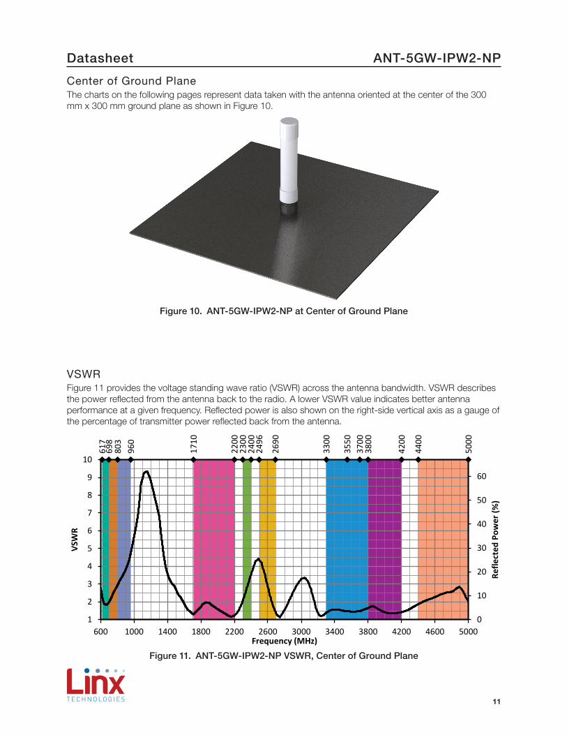
Center of Ground PlaneThe charts on the following pages represent data taken with the antenna oriented at the center of the 300 mm x 300 mm ground plane as shown in Figure 10.
Figure 10. ANT-5GW-IPW2-NP at Center of Ground Plane
VSWRFigure 11 provides the voltage standing wave ratio (VSWR) across the antenna bandwidth. VSWR describes the power reflected from the antenna back to the radio. A lower VSWR value indicates better antenna performance at a given frequency. Reflected power is also shown on the right-side vertical axis as a gauge of the percentage of transmitter power reflected back from the antenna.
617
698
803
960
1710
2200
2300
2400
2496
2690
3300
3550
3700
3800
4200
4400
5000
0
10
20
30
40
50
60
1
2
3
4
5
6
7
8
9
10
600 1000 1400 1800 2200 2600 3000 3400 3800 4200 4600 5000
Refle
cted
Pow
er (%
)
VSW
R
Frequency (MHz)
Figure 11. ANT-5GW-IPW2-NP VSWR, Center of Ground Plane
12
DatasheetANT-5GW-IPW2-NP
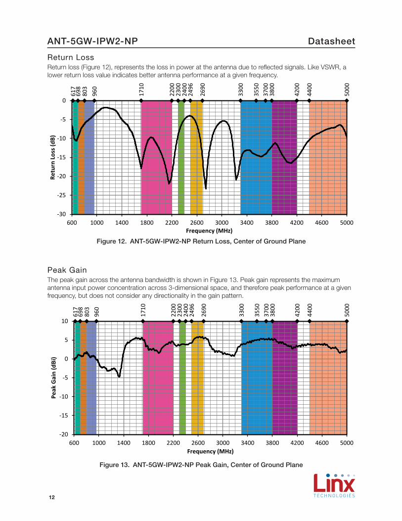
Return LossReturn loss (Figure 12), represents the loss in power at the antenna due to reflected signals. Like VSWR, a lower return loss value indicates better antenna performance at a given frequency.
617
698
803
960
1710
2200
2300
2400
2496
2690
3300
3550
3700
3800
4200
4400
5000
-30
-25
-20
-15
-10
-5
0
600 1000 1400 1800 2200 2600 3000 3400 3800 4200 4600 5000
Retu
rn L
oss (
dB)
Frequency (MHz)
Figure 12. ANT-5GW-IPW2-NP Return Loss, Center of Ground Plane
Peak GainThe peak gain across the antenna bandwidth is shown in Figure 13. Peak gain represents the maximum antenna input power concentration across 3-dimensional space, and therefore peak performance at a given frequency, but does not consider any directionality in the gain pattern.
617
698
803
960
1710
2200
2300
2400
2496
2690
3300
3550
3700
3800
4200
4400
5000
-20
-15
-10
-5
0
5
10
600 1000 1400 1800 2200 2600 3000 3400 3800 4200 4600 5000
Peak
Gai
n (d
Bi)
Frequency (MHz)
Figure 13. ANT-5GW-IPW2-NP Peak Gain, Center of Ground Plane
13
Datasheet ANT-5GW-IPW2-NP
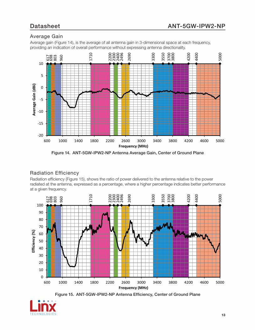
Average GainAverage gain (Figure 14), is the average of all antenna gain in 3-dimensional space at each frequency, providing an indication of overall performance without expressing antenna directionality.
617
698
803
960
1710
2200
2300
2400
2496
2690
3300
3550
3700
3800
4200
4400
5000
-20
-15
-10
-5
0
5
10
600 1000 1400 1800 2200 2600 3000 3400 3800 4200 4600 5000
Aver
age
Gai
n (d
Bi)
Frequency (MHz)
Figure 14. ANT-5GW-IPW2-NP Antenna Average Gain, Center of Ground Plane
Radiation EfficiencyRadiation efficiency (Figure 15), shows the ratio of power delivered to the antenna relative to the power radiated at the antenna, expressed as a percentage, where a higher percentage indicates better performance at a given frequency.
617
698
803
960
1710
2200
2300
2400
2496
2690
3300
3550
3700
3800
4200
4400
5000
0
10
20
30
40
50
60
70
80
90
100
600 1000 1400 1800 2200 2600 3000 3400 3800 4200 4600 5000
Effic
ienc
y (%
)
Frequency (MHz)
Figure 15. ANT-5GW-IPW2-NP Antenna Efficiency, Center of Ground Plane
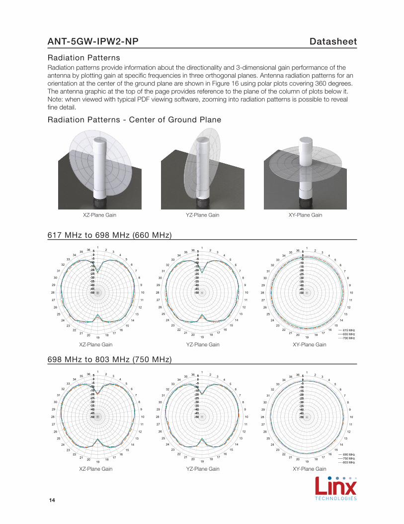
14
DatasheetANT-5GW-IPW2-NP
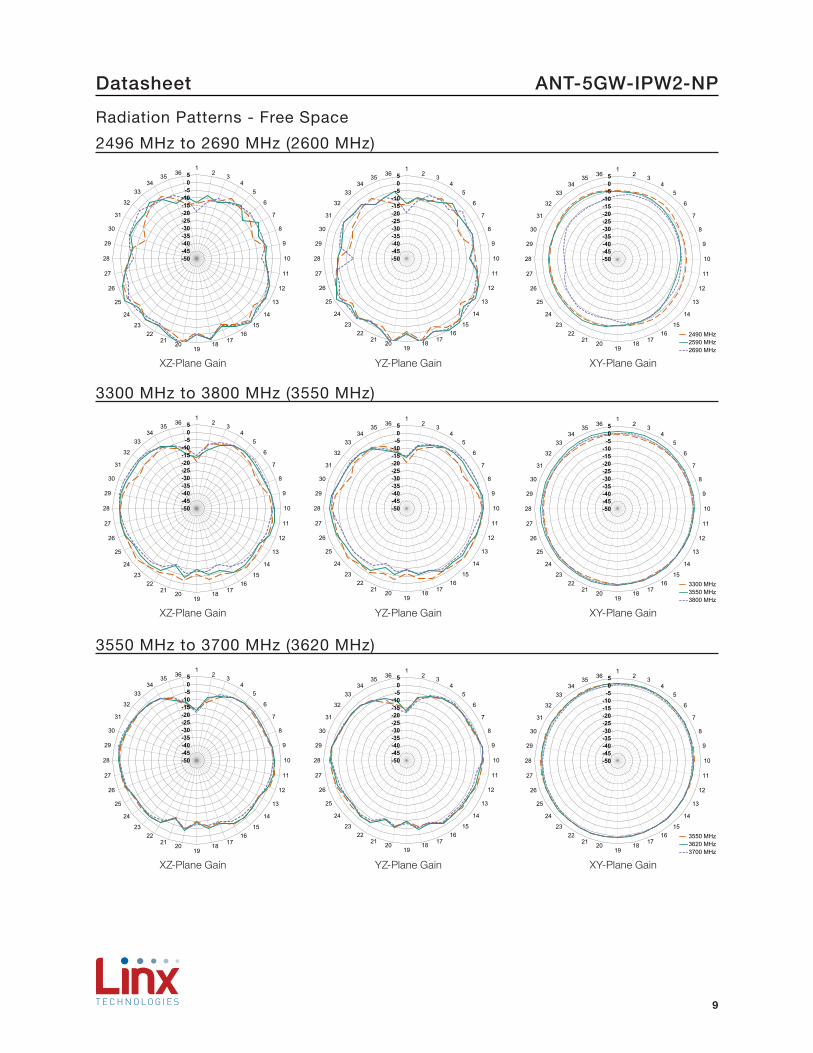
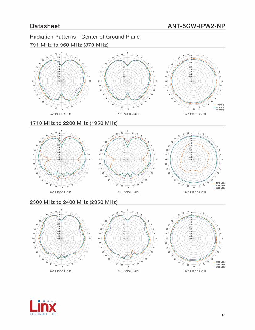
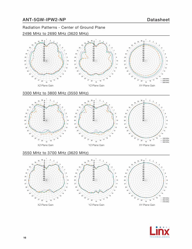
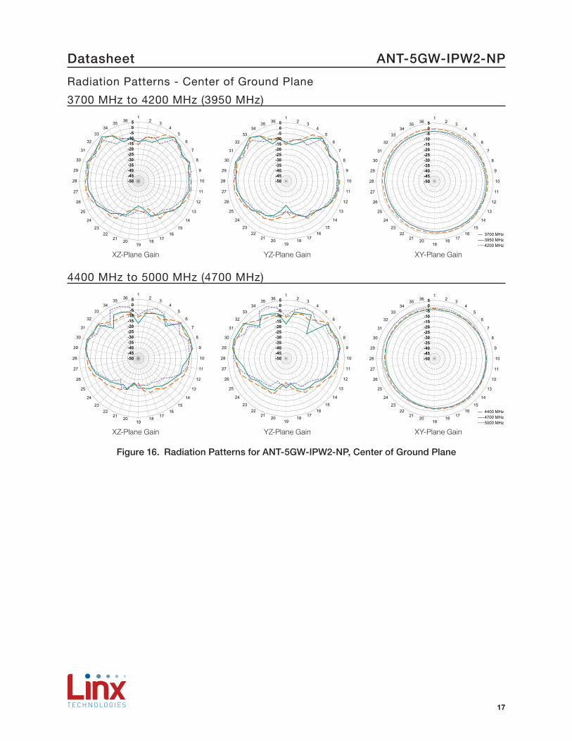
Radiation PatternsRadiation patterns provide information about the directionality and 3-dimensional gain performance of the antenna by plotting gain at specific frequencies in three orthogonal planes. Antenna radiation patterns for an orientation at the center of the ground plane are shown in Figure 16 using polar plots covering 360 degrees. The antenna graphic at the top of the page provides reference to the plane of the column of plots below it. Note: when viewed with typical PDF viewing software, zooming into radiation patterns is possible to reveal fine detail.
Radiation Patterns - Center of Ground Plane
XZ-Plane Gain YZ-Plane Gain XY-Plane Gain
617 MHz to 698 MHz (660 MHz)
-50-45-40-35-30-25-20-15-10
-505
12 3
45
6
7
8
9
10
11
12
13
14
1516
171819
202122
23
24
25
26
27
28
29
30
31
32
3334
35 36
-50-45-40-35-30-25-20-15-10
-505
12 3
45
6
7
8
9
10
11
12
13
14
1516
171819
202122
23
24
25
26
27
28
29
30
31
32
3334
35 36
615 MHz655 MHz700 MHz
-50-45-40-35-30-25-20-15-10
-505
12 3
45
6
7
8
9
10
11
12
13
14
1516
171819
202122
23
24
25
26
27
28
29
30
31
32
3334
35 36
XZ-Plane Gain YZ-Plane Gain XY-Plane Gain
698 MHz to 803 MHz (750 MHz)
-50-45-40-35-30-25-20-15-10
-505
12 3
45
6
7
8
9
10
11
12
13
14
1516
171819
202122
23
24
25
26
27
28
29
30
31
32
3334
35 36
-50-45-40-35-30-25-20-15-10
-505
12 3
45
6
7
8
9
10
11
12
13
14
1516
171819
202122
23
24
25
26
27
28
29
30
31
32
3334
35 36
695 MHz750 MHz803 MHz
-50-45-40-35-30-25-20-15-10
-505
12 3
45
6
7
8
9
10
11
12
13
14
1516
171819
202122
23
24
25
26
27
28
29
30
31
32
3334
35 36
XZ-Plane Gain YZ-Plane Gain XY-Plane Gain
15
Datasheet ANT-5GW-IPW2-NP
791 MHz to 960 MHz (870 MHz)
-50-45-40-35-30-25-20-15-10
-505
12 3
45
6
7
8
9
10
11
12
13
14
1516
171819
202122
23
24
25
26
27
28
29
30
31
32
3334
35 36
-50-45-40-35-30-25-20-15-10
-505
12 3
45
6
7
8
9
10
11
12
13
14
1516
171819
202122
23
24
25
26
27
28
29
30
31
32
3334
35 36
790 MHz875 MHz960 MHz
-50-45-40-35-30-25-20-15-10
-505
12 3
45
6
7
8
9
10
11
12
13
14
1516
171819
202122
23
24
25
26
27
28
29
30
31
32
3334
35 36
XZ-Plane Gain YZ-Plane Gain XY-Plane Gain
1710 MHz to 2200 MHz (1950 MHz)
-50-45-40-35-30-25-20-15-10
-505
12 3
45
6
7
8
9
10
11
12
13
14
1516
171819
202122
23
24
25
26
27
28
29
30
31
32
3334
35 36
-50-45-40-35-30-25-20-15-10
-505
12 3
45
6
7
8
9
10
11
12
13
14
1516
171819
202122
23
24
25
26
27
28
29
30
31
32
3334
35 36
1710 MHz1955 MHz2200 MHz
-50-45-40-35-30-25-20-15-10
-505
12 3
45
6
7
8
9
10
11
12
13
14
1516
171819
202122
23
24
25
26
27
28
29
30
31
32
3334
35 36
XZ-Plane Gain YZ-Plane Gain XY-Plane Gain
2300 MHz to 2400 MHz (2350 MHz)
-50-45-40-35-30-25-20-15-10
-505
12 3
45
6
7
8
9
10
11
12
13
14
1516
171819
202122
23
24
25
26
27
28
29
30
31
32
3334
35 36
-50-45-40-35-30-25-20-15-10
-505
12 3
45
6
7
8
9
10
11
12
13
14
1516
171819
202122
23
24
25
26
27
28
29
30
31
32
3334
35 36
2300 MHz2350 MHz2400 MHz
-50-45-40-35-30-25-20-15-10
-505
12 3
45
6
7
8
9
10
11
12
13
14
1516
171819
202122
23
24
25
26
27
28
29
30
31
32
3334
35 36
XZ-Plane Gain YZ-Plane Gain XY-Plane Gain
Radiation Patterns - Center of Ground Plane
16
DatasheetANT-5GW-IPW2-NP
2496 MHz to 2690 MHz (3620 MHz)
-50-45-40-35-30-25-20-15-10
-505
12 3
45
6
7
8
9
10
11
12
13
14
1516
171819
202122
23
24
25
26
27
28
29
30
31
32
3334
35 36
-50-45-40-35-30-25-20-15-10
-505
12 3
45
6
7
8
9
10
11
12
13
14
1516
171819
202122
23
24
25
26
27
28
29
30
31
32
3334
35 36
2490 MHz2590 MHz2690 MHz
-50-45-40-35-30-25-20-15-10
-505
12 3
45
6
7
8
9
10
11
12
13
14
1516
171819
202122
23
24
25
26
27
28
29
30
31
32
3334
35 36
XZ-Plane Gain YZ-Plane Gain XY-Plane Gain
3300 MHz to 3800 MHz (3550 MHz)
-50-45-40-35-30-25-20-15-10
-505
12 3
45
6
7
8
9
10
11
12
13
14
1516
171819
202122
23
24
25
26
27
28
29
30
31
32
3334
35 36
-50-45-40-35-30-25-20-15-10
-505
12 3
45
6
7
8
9
10
11
12
13
14
1516
171819
202122
23
24
25
26
27
28
29
30
31
32
3334
35 36
3300 MHz3550 MHz3800 MHz
-50-45-40-35-30-25-20-15-10
-505
12 3
45
6
7
8
9
10
11
12
13
14
1516
171819
202122
23
24
25
26
27
28
29
30
31
32
3334
35 36
XZ-Plane Gain YZ-Plane Gain XY-Plane Gain
Radiation Patterns - Center of Ground Plane
3550 MHz to 3700 MHz (3620 MHz)
-50-45-40-35-30-25-20-15-10
-505
12 3
45
6
7
8
9
10
11
12
13
14
1516
171819
202122
23
24
25
26
27
28
29
30
31
32
3334
35 36
-50-45-40-35-30-25-20-15-10
-505
12 3
45
6
7
8
9
10
11
12
13
14
1516
171819
202122
23
24
25
26
27
28
29
30
31
32
3334
35 36
3550 MHz3620 MHz3700 MHz
-50-45-40-35-30-25-20-15-10
-505
12 3
45
6
7
8
9
10
11
12
13
14
1516
171819
202122
23
24
25
26
27
28
29
30
31
32
3334
35 36
XZ-Plane Gain YZ-Plane Gain XY-Plane Gain
17
Datasheet ANT-5GW-IPW2-NP
4400 MHz to 5000 MHz (4700 MHz)
-50-45-40-35-30-25-20-15-10
-505
12 3
45
6
7
8
9
10
11
12
13
14
1516
171819
202122
23
24
25
26
27
28
29
30
31
32
3334
35 36
-50-45-40-35-30-25-20-15-10
-505
12 3
45
6
7
8
9
10
11
12
13
14
1516
171819
202122
23
24
25
26
27
28
29
30
31
32
3334
35 36
4400 MHz4700 MHz5000 MHz
-50-45-40-35-30-25-20-15-10
-505
12 3
45
6
7
8
9
10
11
12
13
14
1516
171819
202122
23
24
25
26
27
28
29
30
31
32
3334
35 36
XZ-Plane Gain YZ-Plane Gain XY-Plane Gain
3700 MHz to 4200 MHz (3950 MHz)
-50-45-40-35-30-25-20-15-10
-505
12 3
45
6
7
8
9
10
11
12
13
14
1516
171819
202122
23
24
25
26
27
28
29
30
31
32
3334
35 36
-50-45-40-35-30-25-20-15-10
-505
12 3
45
6
7
8
9
10
11
12
13
14
1516
171819
202122
23
24
25
26
27
28
29
30
31
32
3334
35 36
3700 MHz3950 MHz4200 MHz
-50-45-40-35-30-25-20-15-10
-505
12 3
45
6
7
8
9
10
11
12
13
14
1516
171819
202122
23
24
25
26
27
28
29
30
31
32
3334
35 36
XZ-Plane Gain YZ-Plane Gain XY-Plane Gain
Radiation Patterns - Center of Ground Plane
Figure 16. Radiation Patterns for ANT-5GW-IPW2-NP, Center of Ground Plane
DatasheetANT-5GW-IPW2-NP
Doc# DS21355-185ANT Replaces (DS21273-185ANT)
Website: http://linxtechnologies.com Linx Offices: 159 Ort Lane, Merlin, OR, US 97532 Phone: +1 (541) 471-6256 E-MAIL: [email protected] Technologies reserves the right to make changes to the product(s) or information contained herein without notice. No liability is assumed as a result of their use or application. No rights under any patent accompany the sale of any such product(s) or information.
Wireless Made Simple is a registered trademark of Linx Acquisitions LLC. Other product and brand names may be trademarks or registered trademarks of their respective owners.
Copyright © 2021 Linx Technologies
All Rights Reserved