OUR STRATEGY TO CONTRUCT LONG SPAN BRIDGES ON...
33
OUR STRATEGY TO CONTRUCT LONG SPAN BRIDGES ON OCEA Technical Seminar on Road Transportation Infrastructure for ASEAN Integration Facility Management & Maintenance Eight - Japan Engineering Consultants Inc. (EJEC) Hirokazu Miyamoto Manager - Presentation o n Performances and Technical Challenges in Our Company for Long Span Bridges Constructing Across Ocean - Department of International June 14th, 2016
Transcript of OUR STRATEGY TO CONTRUCT LONG SPAN BRIDGES ON...

OUR STRATEGY TO CONTRUCT LONG
SPAN BRIDGES ON OCEA
Technical Seminar on Road Transportation Infrastructure for ASEAN Integration
Facility Management & Maintenance
Eight-Japan Engineering Consultants Inc. (EJEC)
Hirokazu MiyamotoManager
- Presentation on Performances and Technical
Challenges in Our Company for Long Span
Bridges Constructing Across Ocean-
Department of
International
June 14th, 2016

Profile of Hirokazu MIYAMOTO
Eight-Japan Engineering Consultants Inc. (EJEC)Page 2
Professional Engineer(Japan) in Civil Engineering Steel &
Concrete), and Soil & Foundation
Master of Civil Engineering, Kumamoto University, Japan, in 1986
Experience of Consultant for 30 years
Main Projects:
【In Japan】
- The Planning and Design the Sub-Structures
on Kurushima Bridge and Tatara Bridge of
Honshu-Sikoku Bridge Authority
- The Detail Design on Viaducts Design in Tokyo
metropolitan outer loop highway Interchanges
- Connecting remote Island Project
【In Over Sea】
- Technical transfer project of JICA in East Africa
- Japan ODA Loan project in Myanmar
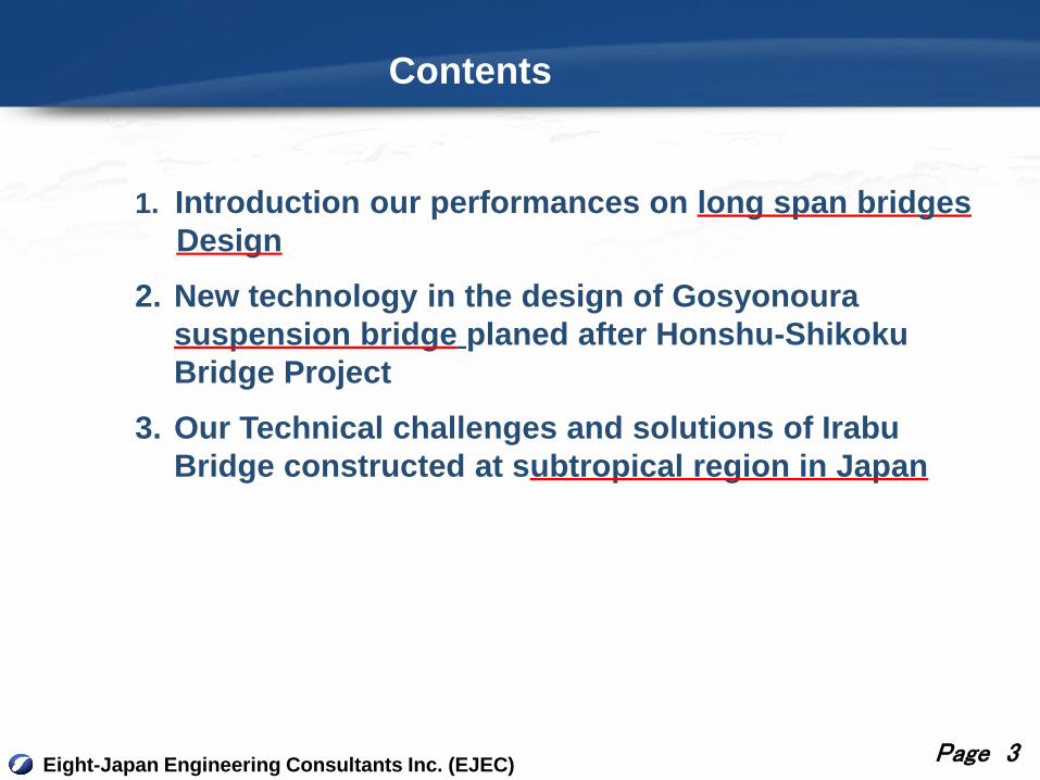
Contents
Eight-Japan Engineering Consultants Inc. (EJEC)Page 3
1. Introduction our performances on long span bridges
Design
2. New technology in the design of Gosyonoura
suspension bridge planed after Honshu-Shikoku
Bridge Project
3. Our Technical challenges and solutions of Irabu
Bridge constructed at subtropical region in Japan
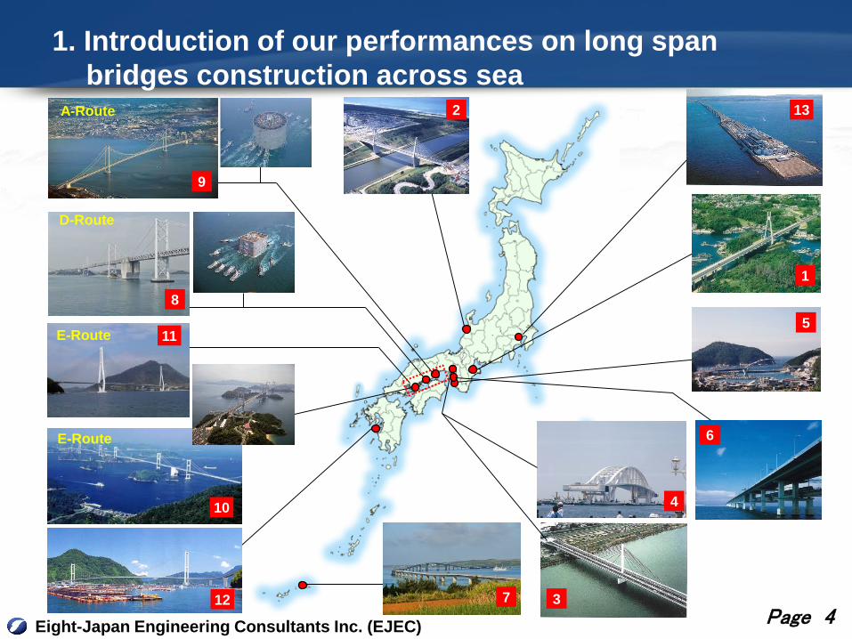
1. Introduction of our performances on long span
bridges construction across sea
Eight-Japan Engineering Consultants Inc. (EJEC)Page 4
A-Route
D-Route
E-Route
E-Route
2
1
5
4
6
7
8
9
10
3
11
12
13

Summary on Bridge (2)
Eight-Japan Engineering Consultants Inc. (EJEC)Page 5
Bridge Name Structure Feature, our performance
1 Shima maruyama BridgePC Cable Stayed Bridge
(L=2@228m)
In that time of the design(1986), this
had one of largest span in Japan
2 Uchinada BridgePC Cable Stayed Bridge
(L=82+180+82m)
A design concept considering salt
damage in concrete shape was
introduced (2001)
3 Torigai-Ninnaji Bridge
Steel Cable Stayed
Bridge
(L=187.5+200m)
Multi fan type used with the largest
strand in the world at the
design(1980)
4 Yumesshima-Maishima BridgeSteel Arch Bridge
(L=410m)
The Largest Floating turning movable
bridge(1992)
5 Totsui BrodgeNielsen-Lohse Bridge
(L=207.5m)Landscape design(1994)
6Kansai International Airport
Bridge
(Sky Gate Bridge R)
Steel Viaduct
(Max span L=150m)
Developed the design method on
(1986)
7 Irabu Bridge Steel & PC Box girderConstruction in sub tropical Region,
refer 3.

Summary on Bridge (2)
Eight-Japan Engineering Consultants Inc. (EJEC)
Tokyo Bay-Aqua line
Page 6
Bridge Name Structure Feature, our performance
8 Great Seto Bridge
Honshyu-
Shikoku
Bridge
Prohect
Suspension Bridge
(1,538+1,643m)
Out lone design on Hitsuishi Island bridge
Design steel laying caisson (1976)
L=3,910(center
1,900m)
Established seismic design method on rigid
body foundation(1986)9Akashi-Kaikyou
Bridge
10 Kurushima Bridge 960+1,515+1,570mPlan, design substructures for main tower
and anchorages, developing seismic design
Cable stayed Bridge We concentrated on substructure design11 Tatara Bridge
12 Gosyonoura BridgeSuspension Bridge
(L=842, center 620m)Post Honsyu-Shikoku project, refer 2.
13Trans-Tokyo Bar Highway
(Tokyo Bay-Aqua line)
Shield Tunnel &
Steel Box Girder
Design of an artificial island for construction
of shield tunnel(1985),
Study on multi span continuous bridge for
the approach bridge(1989)
9.6km
4.4km

2. A Suspension Bridge designed after Honshu-Shikoku
Bridge Project
Eight-Japan Engineering Consultants Inc. (EJEC)Page 7
Gosyonoura Suspension Bridge for connecting remote island
in Kumamoto prefecture
(1) Bridge Length :L = 247+620+75=942 m
(2) Approach Bridge-1 : Five span continuous Steel Box Girder
(3) Main Bridge : Single Span Suspension Bridge (620m)
(4) Approach Bridge-2 : Single span Steel Box Girder
Design duration : from 2.2001 to 2. 2004

2.1 Study on Design Earthquake with Fault Model
Eight-Japan Engineering Consultants Inc. (EJEC)
0 200km100km50km
The Bridge Site
Kumamoto City
Page 8
0 50km20km10km
長崎
熊本
八代
阿蘇山
国見岳
白髪岳
雲仙岳
Futagawa-Hinagu Fault
The Bridge Site
Yatsushiro Seabed fault zone
Beppu-Shimabara Trough
10
100
1000
10000
0.1 1 10
周期 [s]
加速度応答スペクトル
(h=5%
) [cm/s/s]
h=5%
2
Natural Period (sec)
Ac
ce
lera
tio
n R
esp
on
se
Sp
ec
tru
m
(cm
/s/s
)
Design Earthquake Ground Motion
for This Project with Fault Model
Design Earthquake for this projectSpecification-typeⅡ
63km

2.2 Remarkable we had proposed in this Project
Eight-Japan Engineering Consultants Inc. (EJEC)Page 9
① Steel Pipe and ConcreteComposite Tower
② New Concept on Stiffened Box Girder without any stabilizer
③ Developed Tunnel typeAnchorage
V10=39 m/s

2.3 Developed Tunnel Type Anchorage
Eight-Japan Engineering Consultants Inc. (EJEC)Page 10
(1) Profile of Tunnel Anchorage
Anchor girder
Anchor girder
1. Excavate tunnel using incline
system
2. Widen bottom tunnel to store
anchor girder, and to increase
pulling resistance by shear
key
3. Install anchor girder and
frame to fix cable
4. Fill concrete

(2) Stability of Tunnel Anchorage
Eight-Japan Engineering Consultants Inc. (EJEC)Page 11
Fs=
Fs’=
2.0T
ACcosWsinW B ≧・θ・μ・θ・
2.0cosWsin(WT
ACB ≧θ)・μ・θ・-
・
WR ;Own Weigh of Tunnel(kN)
Wc ;Weigh of Rock with unnel (kN)
CB;Cohesion at bottom and side of Tunnel
(kN/m2)
A ; The area of supposed fracture surface (m2)
μ ;Friction Coefficient at Tunnel Bottom
θ ;Inclination angle of tunnel (°)
T ;Cable Tension (kN)
Assumed design fracture surface
(Cylindrical )
Assumed design slip surface
Reduction of soil strength in
consideration of the loosening
of the soil by digging
‐(1)
‐(2)

Comparison with the conventional Type
Eight-Japan Engineering Consultants Inc. (EJEC)Page 12
4A Anchorage
Up
pe
r H
alf
Wid
en
ing
Profile
(comventi
onal
method)
Safety
RateFs =2.50
Excavation
Volume1.00
Lo
we
rH
alf
Wid
en
ing
Profile
(Proposal)
Safety
RateFs =2.45
Excavation
Volume0.91
Ground stress at Loding twice design force背面支圧版のケーブル張力方向変位(上半拡幅案×下半拡幅案)
833.1
12.60
100
200
300
400
500
600
700
800
900
1000
ケーブル張力方向変位(mm)
上半拡幅案
下半拡幅案
設計張力T 2×設計張力T 3×設計張力T
Dis
pla
ce
of
An
ch
ora
ge
(m
m)
Design FORCE T 2×T 3×T
Plane analysis
Upper Half
Widening
Lower Half
Widening

3-D F.E.M Analysis on Tunnel Type Anchorage
Eight-Japan Engineering Consultants Inc. (EJEC)Page 13
Displacement
12.0
m
3.4m
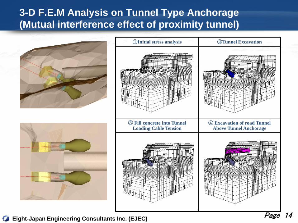
3-D F.E.M Analysis on Tunnel Type Anchorage
(Mutual interference effect of proximity tunnel)
Eight-Japan Engineering Consultants Inc. (EJEC)Page 14
①Initial stress analysis ②Tunnel Excavation
③ Fill concrete into TunnelLoading Cable Tension
④ Excavation of road TunnelAbove Tunnel Anchorage

3. Technical challenges and solutions of Irabu Bridge
constructed at Subtropical region,
Eight-Japan Engineering Consultants Inc. (EJEC)Page 15
Location of Irabu Bridge
1800 km from Tokyo
300 km from Okinawa main island
380 km from Taiwan
NAHA City, Okinawa

3.1 Bridge Structure Summary
Eight-Japan Engineering Consultants Inc. (EJEC)Page 16
Irabu Bridge Total Length is 3,540 m
(1) Miyako Island side : 32-span continuous PC box girder bridges
L=2,185m, Average span length =70m
(2) Main Course: three-span continuous steel box girder bridge
L=320m =120m+180m+120m
(3) Iranu Island side: 14-span continuous PC box girder bridges
L=935 m, Average span =70m
(4) Total number of substructure 50 nos, number of steel pile is about 800
Construction Cost about 360 million US dollar
2,185 m
3,540 m
320 m 935 m
Miyako Island Irabu Island
3.2 Bridge Construction Summary
Eight-Japan Engineering Consultants Inc. (EJEC)
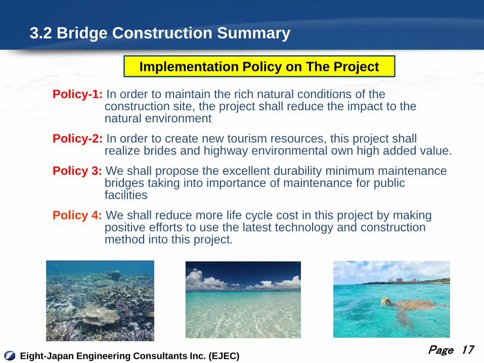
Policy-1: In order to maintain the rich natural conditions of the construction site, the project shall reduce the impact to the natural environment
Policy-2: In order to create new tourism resources, this project shall realize brides and highway environmental own high added value.
Policy 3: We shall propose the excellent durability minimum maintenance bridges taking into importance of maintenance for public facilities
Policy 4: We shall reduce more life cycle cost in this project by making positive efforts to use the latest technology and construction method into this project.
Implementation Policy on The Project
Page 17

3.3 Technical Issues in Construction
Eight-Japan Engineering Consultants Inc. (EJEC)Page 18
Irabu Bridge was awarded the Tanaka Award in 2015 for following reason
This bridge has been constructed in one of the severest environments in
Japan with subtropical heat and humidity, strong wind, and frequent typhoon
attacks.
The design and construction to withstand this severe environment will
contribute significantly to the development of future bridge technology.
1. Aerodynamic Design
Design wind velocity U33=82.2 m/s
In Mainland of Japan usually 40 – 60 m/s
2. Durability Design for Strong Splash including highly concentrated Salt
Exposed to constantly warm moist strong sea breeze
3. Construction Managing for Steel Pile foundation driven into Unique Ground
Technical Issues in Construction

What is Tanaka Award
Eight-Japan Engineering Consultants Inc. (EJEC)Page 19
Tanaka Award was established to honor Dr. Tanaka for his
pioneering contributuion to bridge and structural engineering in
1966
Nowadays the award is counted as one of prestigious and
authoritative awards in the civil engineering field in every year.
1. Outstanding Achievement
2. Excellence in Research Paper
3. Excellence in Bridge Design and Construction
The award is made in the three categories:

3.3 Our Solutions to Improve Durability and Maintenance(1) Steel Box Girder Bridge at Main Course (120m+180m+120m)
Eight-Japan Engineering Consultants Inc. (EJEC)Page 20
Aerodynamic Design Steel Floor-Slab Box-Girder Bridge
Steel Box Girder type was chosen from many type bridge in
considering following conditions;
i. Aerodynamic Stability
(peak gust 87m/s)
i. Reduce Maintenance works in future
ii. Safety during erection works
(this area has heavy wind more than 10m/sec in every day
excluding a short season)
It was the first experience in Japan to erect a long span bridge on
sea under such sever natural conditions.

New Concepts of Steel Box Girder in Japan
Eight-Japan Engineering Consultants Inc. (EJEC)Page 21
■ Flat shape box girder having any projections
1) Realization of high wind stability without any additional aerodynamic stabilizer the wind velocity for nominal vibration > 82.2 m/sec
the wind velocity for divergent vibration > 108.5 m/sec
2) Reduction of salt adhesion amount
Minimization of surface area
Rinsing adhesion salinity on surface by rain
3) Improve a workability for welding joint in the situ
16,100 (mm)
3,200 3,2009,700
3,5
00
These implementation requires high construction
techniques of Japan such as full circumferential
welding in the situ and marine erection, etc.

Construction Procedure of Main Course Steel Bridge
Eight-Japan Engineering Consultants Inc. (EJEC)Page 22
① Main girder transportationfrom Japan Mainland ②Preparation at near site ③Transportation to the site
④ Erection at the site by
floating crane ⑤ Circumference welding
of box girder in the situ

(2) Continuous PC Box Girder Bridges
Eight-Japan Engineering Consultants Inc. (EJEC)Page 23
Continuous PC box girder by travelling erection girder is one of most
popular bridge type in remote islands connecting project in Okinawa
prefecture.
New technologies introduced into this project in order to more enhance
durability for soil damage and reduce maintenance are follows;
(1) Post sliding construction method to achieve multi-continuous bridge
(2) Antirust pc cable and re-bar coated by epoxy resin
(3) Apply Fly Ash Cement which has lower permeability
(4) EStablish Monitoring system to research chloride ion penetration into
concrete

Various Countermeasures for Chloride
Eight-Japan Engineering Consultants Inc. (EJEC)Page 24
(1) Post sliding method to send back bearing deformation
① Bearing deformation
due to Shrinkage and Creep② Send back
(2) Epoxy resin-coat
① Coated Reinforce ② Coated PC cable
(a) Coated wire
(b) PE cover + Coated wire

(3) Fly Ash Cement
Eight-Japan Engineering Consultants Inc. (EJEC)Page 25
Depth from surface(mm)
ch
lori
de io
n c
on
ce
ntr
ati
on
(kg
/m3)
Survey Result
on Existing Bridges used normal
portland cement in Okinawa
PORTLAND CEMENT
■ Expected Effects
Improvement of water-tightness and durability
Improvement of salt penetration resistance
Inhibition of alkali aggregate reaction
Suppression of the temperature rise due to hydration heat
Improvement of consistency, and Decrease unit quantity of water
Reduction of shrinkage
■ Disadvantage
Slow exertion of strength
Use to only substructure in this project
Based on the experience in this project, Fly Ash cement Concrete will
become a standard in Okinawa Region

Monitoring Plan on Chloride concentration in Concrete
Eight-Japan Engineering Consultants Inc. (EJEC)Page 26
CAESAR(Center for Advanced Engineering
Structural Assessment and Research) and
Okinawa prefecture are monitoring
Chloride Concentration jointly.
This survey results will help a maintenance
of this bridge, and is hoped to advance
more effective chloride countermeasure
design
Concrete coring plan for monitoring
Concrete spacemen for exposure test
ch
lori
de io
n c
on
ce
ntr
ati
on
(kg
/m3)
Depth from surface(mm)
3.4 Design and Construction Managing for Steel Pile
Foundation Driven into Unique Ground
Eight-Japan Engineering Consultants Inc. (EJEC)Page 27
1. What are Issues for Driven Pipe Pile Foundation ?
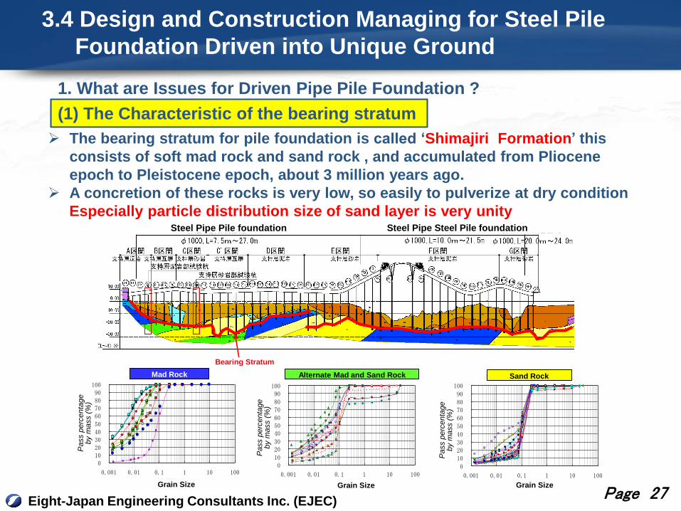
(1) The Characteristic of the bearing stratum
The bearing stratum for pile foundation is called ‘Shimajiri Formation’ this
consists of soft mad rock and sand rock , and accumulated from Pliocene
epoch to Pleistocene epoch, about 3 million years ago.
A concretion of these rocks is very low, so easily to pulverize at dry condition
Especially particle distribution size of sand layer is very unity
粒径加積曲線(砂岩-褐色)
0102030405060708090
100
0.001 0.01 0.1 1 10 100粒径(mm)
通過質量百分率(%)
粒径加積曲線(泥岩)
0102030405060708090
100
0.001 0.01 0.1 1 10 100
粒径(mm)
通過質量百分率(%)
粒径加積曲線(砂岩-暗灰色)
0102030405060708090
100
0.001 0.01 0.1 1 10 100粒径(mm)
通過質量百分率(%)
Grain Size
Pa
ss p
erc
en
tag
e
by m
ass (
%)
Grain Size
Pass p
erc
enta
ge
by m
ass (
%)
Pass p
erc
enta
ge
by m
ass (
%)
Grain Size
Mad Rock Sand RockAlternate Mad and Sand Rock
Steel Pipe Pile foundation Steel Pipe Steel Pile foundation
Bearing Stratum
1. What are Issues for Driven Pipe Pile Foundation?
Eight-Japan Engineering Consultants Inc. (EJEC)Page 28
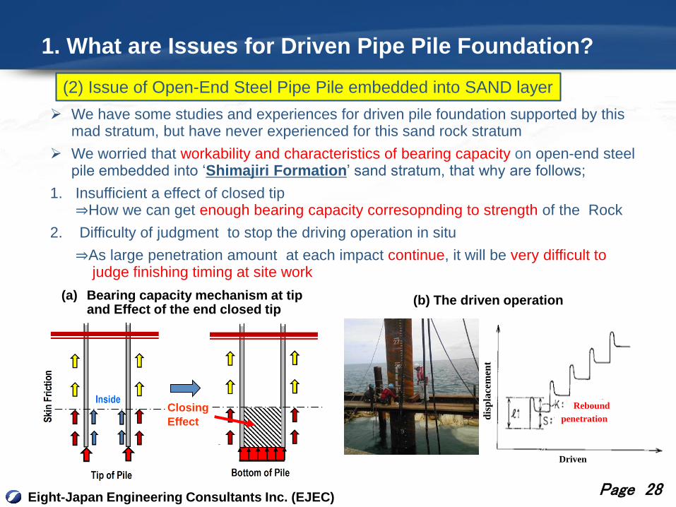
We have some studies and experiences for driven pile foundation supported by this mad stratum, but have never experienced for this sand rock stratum
We worried that workability and characteristics of bearing capacity on open-end steel pile embedded into ‘Shimajiri Formation’ sand stratum, that why are follows;
1. Insufficient a effect of closed tip⇒How we can get enough bearing capacity corresopnding to strength of the Rock
2. Difficulty of judgment to stop the driving operation in situ
⇒As large penetration amount at each impact continue, it will be very difficult tojudge finishing timing at site work
(2) Issue of Open-End Steel Pipe Pile embedded into SAND layer
(b) The driven operation
Rebound
penetration
Driven
dis
pla
cem
ent
Closing
Effect
(a) Bearing capacity mechanism at tipand Effect of the end closed tip
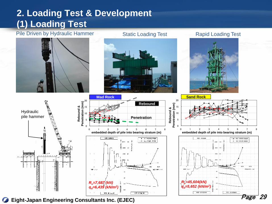
2. Loading Test & Development
(1) Loading Test
Eight-Japan Engineering Consultants Inc. (EJEC)
Static Loading Test Rapid Loading TestPile Driven by Hydraulic Hammer
0
5
10
15
20
0 1 2 3 4 5 6 7 8
支持層への根入れ比
貫入量
(
mm
)
リバウンド量
反力杭貫入量 反力杭リバウンド量 試験杭貫入量 試験杭リバウンド量
0
5
10
15
20
0 1 2 3 4 5 6 7 8
支持層への根入れ比
貫入量
(
mm
)
リバウンド量
反力杭貫入量 反力杭リバウンド量 試験杭貫入量 試験杭リバウンド量
embedded depth of pile into bearing stratum (m) embedded depth of pile into bearing stratum (m)
Reb
ou
nd
&
Pen
etr
ati
on
(m
m)
Reb
ou
nd
&
Pen
etr
ati
on
(m
m)
Rebound
Penetration
Mad Rock Sand Rock
Hydraulic
pile hammer
Page 29
Ru=7,687 (kN)
qd=6,439 (kN/m2)
Ru=45,604(kN)
qd=5,652 (kN/m2)

(2) Our Study and Solutions
Eight-Japan Engineering Consultants Inc. (EJEC)Page 30
Establish an arc ribs steel pipe pile aimed at the high effects of
end closed
Strategic application of reinforcing structure at tip in accordance
with ground condition at each foundation
In order to realize the above, re-check existing geological survey
results carefully
Evaluating a bearing capacity at pile , and Establishing a
management criteria for finishing driving operation in situ
Arc ribs steel
pipe pile
Standard type with
reinforcing bandStandard type without
reinforcing band
OR
Sand Rock Alternate Mad and Sand Rock
Reinforcing Band

(3) Results
Eight-Japan Engineering Consultants Inc. (EJEC)Page 31
CATEGORY-1 CATEGORY-3
CATEGORY-4CATEGORY-2
CATEGORY-1 CATEGORY-2 CATEGORY-3 CATEGOTY-4
Bearing Stratum Mad Rock Sand Rock Sand Rock Mad & Sand Mix
Type of Pole Normal with Band Normal with Band Arc Rib Pile Normal without Band
Target Embedded Depth 2.0m (L/D=2) 5.0m (L/D=5) 2.0m(L/D=2) 3.0m(L/D=3)
Loading Test
qd (kN/m2) at pile tip6,439 (8,021) 7.996 8,021
RemarksThere are obstacle in the
intermediate layer
Expect enough Effect of
end Closed
Criteria for Finishing Driving Operation
Results of Pile Driving Works

Thank you for your kind attention
Please contact me if there are any question!
Hirokazu Miyamoto
E-mail: [email protected] Engineering Consultants Inc. (EJEC)
Department of International
Page EndEight-Japan Engineering Consultants Inc. (EJEC)

Eight-Japan Engineering Consultants Inc. (EJEC)Page 33