Our solutions for your service - Europages
88
Transcript of Our solutions for your service - Europages

Our solutions for your service
Lifting without limits
Whether you are a customer from the commercial sphere,industry, or one of the skilled trades, you, your staff,and above all your customers can benefit from PLANETA‘sexperience in design, production, maintenance and tradein the lifting technology business.The flat hierarchies of our family business allow usto react quickly and flexibly to your particular need,with competitive pricing.
Price / performance ratio
We strive to provide you with the best solution at the bestpossible price, and this goes well beyond the lifting deviceitself. To us, the best quality means always showing you thesolution which corresponds precisely to your requirementsin the areas of lifting, pulling and lowering.
Trust is good – control is better
PLANETA lifting devices are subject to the strictest qualitycontrols and also designs for the toughest operatingconditions. All lifting equipment that leaves our factory istested above its normal loading and issued with a testcertificate and serial number.Thus we can ensure that your PLANETA lifting devices willserve your production needs both continuously and reliably.
Service life and functionality
During the development and production of our liftingdevices, we place value not only on a long service life,but also on a high level of functionality, maximumsafety for the user, and an appealing design.
Availability and punctual delivery
Our large central warehouse for standard productsand spare parts in Herne, as well as a network of trainedPLANETA specialist dealers guarantees high levels ofavailability, for standard items often within 24 hours.
1
Our solutions for your service
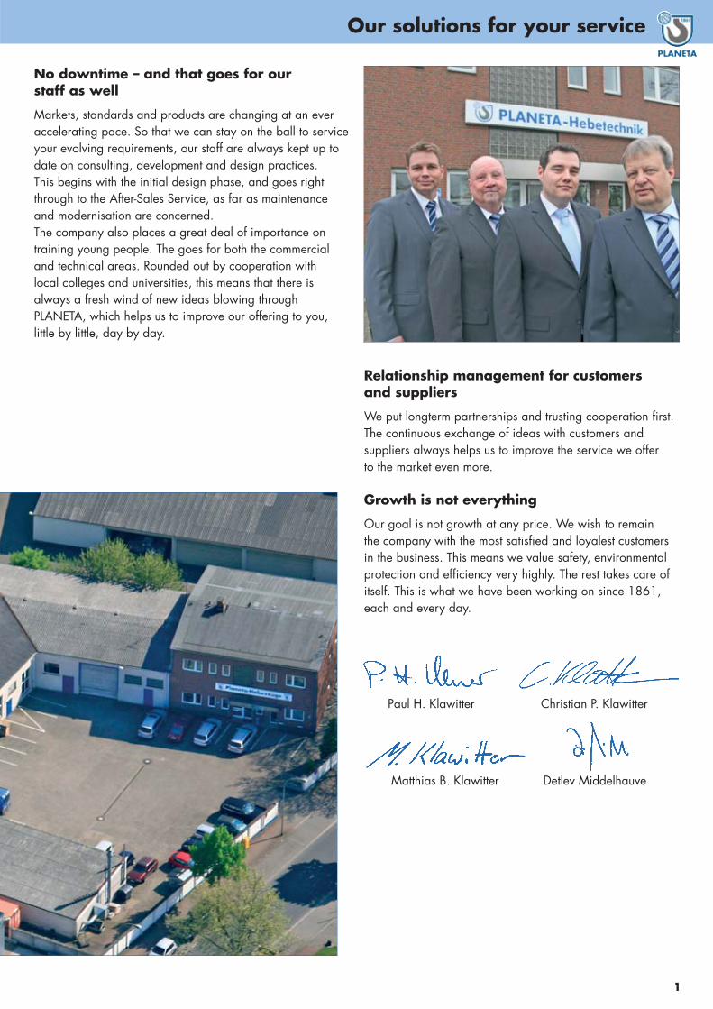
No downtime – and that goes for ourstaff as well
Markets, standards and products are changing at an everaccelerating pace. So that we can stay on the ball to serviceyour evolving requirements, our staff are always kept up todate on consulting, development and design practices.This begins with the initial design phase, and goes rightthrough to the After-Sales Service, as far as maintenanceand modernisation are concerned.The company also places a great deal of importance ontraining young people. The goes for both the commercialand technical areas. Rounded out by cooperation withlocal colleges and universities, this means that there isalways a fresh wind of new ideas blowing throughPLANETA, which helps us to improve our offering to you,little by little, day by day.
Relationship management for customersand suppliers
We put longterm partnerships and trusting cooperation first.The continuous exchange of ideas with customers andsuppliers always helps us to improve the service we offerto the market even more.
Growth is not everything
Our goal is not growth at any price. We wish to remainthe company with the most satisfied and loyalest customersin the business. This means we value safety, environmentalprotection and efficiency very highly. The rest takes care ofitself. This is what we have been working on since 1861,each and every day.
Paul H. Klawitter Christian P. Klawitter
Matthias B. Klawitter Detlev Middelhauve

Note: PLANETA are constantly striving to increase and further improve the product range. Whilst every effort has been made to ensure the accuracy of the specificationsand dimensions included at the time of printing, we are unable to warrant the given information. Designs and specifications are subject to change without notice orobligation. The inclusion of any product does not guarantee the availability of that product in the future. Customers should check both the availability and conformance ofthe product to any critical parameters at the time of ordering!
© 2014 by PLANETA® – Form 05/HKE
Page 3-22
Page 23-34
2
Übersicht
1
2
Page 35-443
Page 45-704
Page 71-845
Content of catalogue
Manual lifting and pulling equipmentLever hoists, Manual chain hoists, Grip pullers, Trolleys,
Low headroom trolley hoists, Super-low combined trolley hoists, Beam clamps
EX-proofEX-proof manual chain hoists, EX-proof push and geared trolleys,
Air chain hoists, Air rope hoists, Air supply
Electric hoistsElectric chain hoists GCH, Trolleys for electric hoists, Electric rope hoists
Rope winchesWinch options, Wire ropes, Electric rope winches, Electric rope winch PFW,
Electric rope winch PORTY, Worm gear winch types, Compact rope winches,
Planetary gear winches, Capstans, Manual rope winches
Lifting and transporting accessoriesFlat webbing slings, Round slings, Ratchet lashing, Chain slings,
Magnetic lifter, Plate clamps, Hydraulic pallet truck, Hydraulic jacks,
Mechanical steel jacks

SEIT 1861Vorspann fehlt
3
1

HebelzugPLANETA hoists
4
1
Overview of PLANETA manual hoists:
General Information
PLANETA hoists and trolleys are designed to have a longservice life even under the toughest operating conditions andcomply with the machinery directive. Each hoist that leaves ourfactory is tested with an appropriate excess load beforedelivery. This is certified in an inspection report when a serialnumber is assigned, and is enclosed with the item.
When developing our hoists, we do not only placevalue on a long service life, but also on absolutefunctionality, maximum safety during use and anappealing design.
We only use galvanised load chains that conform to DIN EN 817-7-T and that are manufactured in Germany orEurope, in order to guarantee the highest level of safety.
We guarantee that spare parts will be available for a long timeso that you can work with your hoist for many years.
We are happy to assist you with the recommended annualinspection of your hoists by passing you on to a designated,trained PLANETA service partner throughout the entirefederal territory.
Lever hoistsOur WICHTEL, PREMIUM PRO (for the highest quality), PLANETA-AH(low weight), PMH and PLX-II (as a standard model) hoists providesafe lifting, pulling and securing forload bearing capacities of up to 9 t.This is virtually unique in the hoistmarket.
Chain hoists PLANETA pulley hoists arealways used if there is nopower supply (e.g. duringmaintenance tasks) or ifacquiring a motor-driven hoistdoes not make sense from aneconomic perspective, as itwill only be used occasionally.Our product range includesthe established PLM-II and thePREMIUM PRO for load bearingcapacities of up to 30 t.
Grip pullerPLANETA-Ropemasters for upto 5400 kg have been usedfor many years in structuraland civil engineering, open line construction and in forestry to pull and secureloads.
Beam clampsThe BK beam clamp and the BRroller clamp are suited as mobileattachment points on assemblies;the BR design is also suited as atrolley for up to 10 t. The galvanised spindle guaranteesa long service life.
Trolleys Regardless of whether you choosethe standard PT/GT design, thestrengthened L series or the pulleyhoist-trolley combination for thelowest construction heights,PLANETA trolleys provide thesafety, quietness and flexibility tomeet your requirements.

WICHTEL 50
Hebelzug
1
5
Lever hoist
Only
235
mm
Mini-lever hoistPLANETA – WICHTEL 25 and WICHTEL 50
A really small and lightweight helper for any kind of assemblingwork, pulling and lifting jobs. Only 23 cm in total length, thehoist can be used in just about any small space and in anydirection. The handle can be cranked 360o but only 12 positionloads are required. That’s a big plus in tight places! Doublereduction gearing provides superior spotting character. The hoist isvery safe for lifting with two ratchet pawls and an innovative discbrake system that also allows unloaded free chaining. WICHTEL 25and WICHTEL 50 has a fully chrome plated housing plus arubber grip with slip resistant shape.The hoist comes with a 1.5 m high tensile load chainacc. DIN EN 818-7-T. Top and load hook havespecial safety latches.
WICHTEL 25 is fullygalvanised!It is the smallest hoist withinthe PREMIUM series.
TYPE WICHTEL 25 WICHTEL 50
Capacity kg
Standard lift m
Min. headroom (A) mm
Lever force daN
Chain size mm
B (Dimensions) mm
C mm
D mm
E mm
F mm
G mm
Weight with standard lift kg
Weight for 1 m additional lifting height kg
250
1.5
235
30
4 x 12
60
155
31
19
91
70
2.8
0.4
500
1.5
300
24
5 x 15
118
253
31
24
143
86
5.7
0.6
WICHTEL ... with 1.5 m lift Order No. G10013 G10030
Additional 1 m lift Order No. G10007 G10036
1
With integrated chain guide for trouble-free and
smooth chaining
WICHTEL 25

Seilzuggerät
1
Lever hoist
6
Safety brake with two pawls
Drop-forged load hookwith closed and fitting
safety latch
Chromed steel plate housing
Large, non-sliphand wheel
Extra-secure handle
Chain end piecewith robust nylon design
Integrated chain guide
Reversing lever with free-
running mode
Tempered and galvanized load chain acc. DIN EN 818-7-T
Option: Overload protection

Seilzuggerät
1
7
Lever hoist
Lever hoist PLANETA – PREMIUM PROThe next development stage of the reliable PREMIUM lever hoist is the PREMIUM PRO.Thanks to a significant weight saving, handling is improved. Despite this, the frame has beenstrengthened compared to the previous generation.Proven quality also ensures longevity and its design makes it very robust.
Free-running modeWhen the selection switch is moved to the middle point, the unladen chain can easily bepulled through the device freely to the required usage length.This makes tensioning the chain easier.
Load chainThe tempered, galvanised load chain according to DIN EN 818-7-T is supplied with the unit.The standard lifting height is 1.5 m; any length required for higher lifting is possible.
New chain end pieceThe robust chain end piece provides additional safety because it cannot be pulled throughthe device with the chain.
Protected handleThe ergonomic rubber handle on the end of the lever protects the useragainst injury and is also screwed in place to prevent it slipping.
Technical advantagesHand lever can be used in any position thanks to the ratchet; safety automaticmechanical brake; galvanised connecting parts; cast hook clip; large, non-slip andclosed hand wheel; safety chain end piece.
PREMIUM PRO 6 t
Options:
• Also in -design
• With overload protection
PREMIUM PRO1.5 t
TYPE PREMIUM PRO … 0,75 1,5 3 6 9
Capacity t
Standard lift m
Min. headroom (A) mm
Lever force daN
Number of chain falls
Chain size mm
B (Dimensions) mm
C mm
D mm
E mm
E1 mm
F mm
G mm
Weight with standard lift kg
Weight for 1m additional lifting height kg
0.75
1.5
320
22
1
5.6 x 17
115
239
35
35
23
91
146
5.3
0.7
1.5
1.5
360
24
1
7.1 x 21
137
259
42
38
28.5
67
162
8.6
1.1
3
1.5
431
33
1
9 x 27
169
374
48
46
33
98
187
15.2
1.8
6
1.5
500
36
2
9 x 27
238
374
60
59
39
98
187
23
3.6
9
1.5
635
38
3
9 x 27
300
374
70
54
51
98
187
43
5.4
PREMIUM PRO ... with 1,5 m lift Order No. G10290 G10291 G10292 G10293 G10294
Additional 1m lift Order No. G10086 G10087 G10249 G10254 G10256
0.75 – 3 t 9 t

Only
285
mm
PMH 500
Flaschenzug
1
Lever hoist
8
Mini lever hoist PLANETA – PMHThe new PLANETA PMH mini lever hoist impressesdespite its low net weight and minimal size – forprofessional use in smaller load ranges. It is the idealappliance for assembly tasks, in industry, in trade orin the service area.It can be used for lifting, pulling, aligning and stretchingin any location and in any direction.
Steel housingThe closed housing is made of steel plates, is extremelyrobust and protects the chain drive against dirt.
BrakeThanks to the integrated automatic mechanical brake,the load is held completely securely in all positions.
HooksThe carrying and load hooks made of forged steelare fully rotatable and equipped with spring-loadedsafety clips.
Load chainTempered and galvanised load chain according toDIN EN 818-7-T.
Chain free-running modeBy quickly reversing the selection lever to the middlesetting, the chain can be pulled through freely withminimal effort.
Hand leverThe rubberised hand lever protects against injuries tohands and enables loads to be lifted and lowered easily.
Storage bagA practical nylon bag with a belt strap is supplied withthe unit.
TYPE PMH 250 PMH 500
Capacity kg
Standard lift m
Min. headroom (A) mm
Lever force daN
Chain size mm
B (Dimensions) mm
C mm
D mm
E mm
F mm
G mm
H mm
J mm
Weight with standard lift kg
Weight for 1 m add. lifting height kg
250
1.5
245
26
4 x 12
86
170
32
23
97
77
155
79
2.2
0.35
500
1.5
285
26
4 x 12
95
170
36
24
117
80
178
87
3.2
0.35
PMH ... with 1,5 m lift Order No. G10028 G10029
Additional 1 m lift Order No. G10007 G10007
Only
245
mm
PMH 250
The PMH can be carried easily onthe belt and is always to hand.

Preciselychain guide
All external partsgalvanic zinc plated
PLX- II 1.5 t
PLX- II 6 t
Forged safety hookswith accurately fitting
hook clips
0.75 – 3 t 6 t
PLANETA – PLX-II lifting and anchoring deviceThe PLANETA PLX-II lever hoist is an extremely versatilelifting and anchoring device but is easy to handle.It is used in the industrial area, in commercial transport, as anaid during assembly and in construction and the trades.This device stands out thanks to the high quality of serial productionand its long service life even if operational demands are high.
Simple free-running modeWhen the selection switch is moved to the middle point, the unladenchain can easily be pulled though the device freely.
New chain end pieceIn the unlikely case of a brake failure, this serves as an additionalsafety device because it cannot be pulled through the device with theload chain and therefore the load is held reliably.
Connecting partsGalvanised screws, nuts and bolts prevent corrosion, even ifused outdoors.
Rotatable hooksThe forged carrying and load hooks made of heat-treated, temperedsteel are fully rotatable and equipped with spring-loaded, galvanisedhook clips.
TYPE PLX-II ... 0,75 1,5 3 6
Capacity t
Standard lift m
Min. headroom (A) mm
Lever force daN
Number of chain falls
Chain size mm
B (Dimensions) mm
C mm
D mm
E mm
E1 mm
F mm
G mm
Weight with standard lift kg
Weight for 1 m add. lifting height kg
0.75
1.5
340
20
1
6 x 18
135
296
37
26.5
21
150
90
6.5
0.7
1.5
1.5
360
26
1
7.1 x 21
160
420
37
33
27.5
170
98
10
1.1
3
1.5
480
38
1
10 x 30
210
420
47
40.5
34
190
105
18.5
2.2
6
1.5
600
39
2
10 x 30
250
420
69
47
42
190
105
33
4.4
PLX-II... with 1,5 m lift Order No. G10230 G10231 G10232 G10233
Additional 1 m lift Order No. G10009 G10068 G10011 G10012
1
9
Lever hoist

Laufkatzen
1
Manual chain hoist
10
TYPE PREMIUM PRO... 0,25 0,5 1 1,5 2 3 5 10 20 30
Capacity t
Standard lift m
Min. headroom (A) mm
Hand chain force daN
Hand chain operation length m
Number of chain falls
Chain size mm
B (Dimensions) mm
C mm
D mm
E mm
F m
Weight with 3 m lift kg
Weight for 1 m additional lift kg
0.25
3
259
22
2.5
1
4 x 12
95
99.4
30
22
2.5
4.2
0.35
0.5
3
309
24
2.5
1
5 x 15
114
110
33
22
2.5
5.7
0.55
1
3
373
30.5
2.5
1
6 x 18
152
139
40
28
2.5
10.8
0.78
1.5
3
460
36
2.5
1
8 x 24
190
150
52
33
2.5
16.8
1.4
2
3
460
36
2.5
1
8 x 24
190
150
52
33
2.5
17.1
1.4
3
3
553
37
2.5
1
10 x 30
240
158
62
37
2.5
26.2
2.2
5
3
630
39
2.5
2
10 x 30
240
158
72
44
2.5
40
4.4
10
3
900
39.5
2.5
4
10 x 30
391
166
85
60
2.5
62
8.8
20
3
1033
40.5
2.5
8
10 x 30
955
169
110
70
2.5
160
17.6
30
3
1320
47 x 2
2.5
12
9 x 27
690
435
106
80
2.5
350
21.6
PREMIUM PRO ... with 3 m lift Order No. G10310 G10311 G10312 G10313 G10314 G10315 G10316 G10317 G10318 G10062
Additional 1 m lift Order No. G10270 G10271 G10242 G10243 G10243 G10272 G10246 G20247 G10248 G10058
Chain bag (plastic) up to 3 m lift Order No. H10057 H10057 H10057 H10059 H10059 – – – – –
PREMIUM PRO1 t
PLANETA – PREMIUM PROCompact and light
The new PREMIUM-PRO chain hoist is the systematic developmentof the established PREMIUM series and is manufactured using thelatest technology. Compared to its predecessors, it is much lighter andprovides better handling thanks to its compact design.
Despite the weight saving, working stability has been improved thanksto the clever construction. The chrome-plated housing for corrosionprotection and overload protection as standard reinforce the high qualityof the PLANETA-PREMIUM PRO product.
Load chainTempered and galvanised load chain „Made in Germany“ according toDIN EN 818-7-T. Up to 3 t in a single strand.Higher lifting on request, any length can be delivered.
Galvanised or chromated on all sidesDirt or rain have no effect on this device.All connection and housing parts are protected against corrosion.
Chain mountingThanks to the easily-accessible chain mounting, any user can insert alonger chain if required.
PREMIUM PRO5 t
0,25 – 3 t 5 t 10 t
PREMIUM PRO10 t
1
Manual chain hoist
11
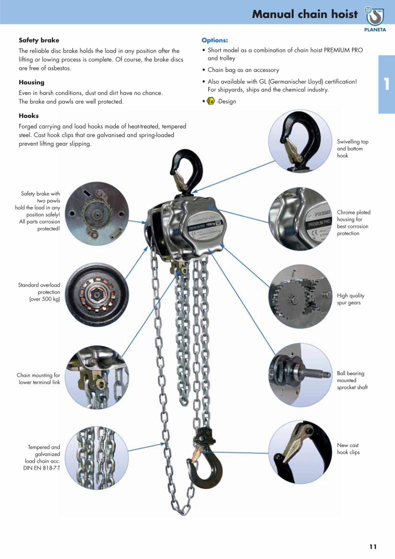
Safety brake
The reliable disc brake holds the load in any position after thelifting or lowing process is complete. Of course, the brake discsare free of asbestos.
Housing
Even in harsh conditions, dust and dirt have no chance.The brake and pawls are well protected.
Hooks
Forged carrying and load hooks made of heat-treated, temperedsteel. Cast hook clips that are galvanised and spring-loadedprevent lifting gear slipping.
Options:
• Short model as a combination of chain hoist PREMIUM PRO and trolley
• Chain bag as an accessory
• Also available with GL (Germanischer Lloyd) certification!For shipyards, ships and the chemical industry.
• -Design
Safety brake withtwo pawls
hold the load in anyposition safely!
All parts corrosionprotected!
Standard overloadprotection
(over 500 kg)
Chain mounting forlower terminal link
Tempered andgalvanized
load chain acc.DIN EN 818-7-T
Swivelling topand bottomhook
Chrome platedhousing forbest corrosionprotection
High qualityspur gears
Ball bearingmountedsprocket shaft
New casthook clips
Seilzuggerät
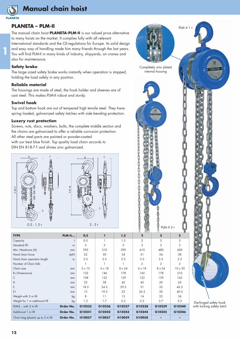
PLANETA – PLM-IIThe manual chain hoist PLANETA-PLM-II is our valued price alternativeto many hoists on the market. It complies fully with all relevantInternational standards and the CE-regulations for Europe. Its solid designand easy way of handling made him many friends through the last years.You will find PLM-II in many kinds of industry, shipyards, on cranes andalso for maintenance.
Safety brakeThe large sized safety brake works instantly when operation is stopped,holding the load safely in any position.
Reliable materialThe housings are made of steel, the hook holder and sheeves are ofcast steel. This makes PLM-II robust and sturdy.
Swivel hookTop and bottom hook are out of tempered high tensile steel. They havespring loaded, galvanized safety latches with side bending protection.
Luxery rust protectionScrews, nuts, discs, washers, bolts, the complete middle section andthe chains are galvanized to offer a reliable corrosion protection. All other steel parts are painted or powder-coated with our best blue finish. Top quality load chain accords toDIN EN 818-7-T and shines zinc galvanized.
0.5 - 1.5 t 2 - 5 t
Completely zinc plated internal housing
PLM- II 5 t
PLM- II 1 t
Die-forged safety hookwith locking safety latch
1
Manual chain hoist
12
TYPE PLM-II... 0,5 1 1,5 2 3 5
Capacity t
Standard lift m
Min. Headroom (A) mm
Hand chain force daN
Hand chain operation length m
Number of Chain falls
Chain size mm
B ( Dimensions) mm
C mm
D mm
E mm
E1 mm
Weight with 3 m lift kg
Weight for 1 m additional lift kg
0.5
3
295
22
2.5
1
5 x 15
122
108
32
18.5
15
8
1.2
1
3
310
30
2.5
1
6 x 18
146
122
38
24.5
19.5
11
1.7
1.5
3
390
34
2.5
1
8 x 24
178
139
42
29.5
22
15
2.3
2
3
410
31
2.5
2
6 x 18
142
122
45
31
26.5
14
2.5
3
3
480
34
2.5
2
8 x 24
178
139
50
33
30
25
3.7
5
3
600
38
2.5
2
10 x 30
210
162
65
45.5
40.5
36
5.3
PLM-II... with 3 m lift Order No. G10235 G10236 G10237 G10238 G10239 G10240
Additional 1 m lift Order No. G10241 G10242 G10243 G10244 G10245 G10246
Chain bag (plastic) up to 3 m lift Order No. H10057 H10057 H10059 H10058 – –
13
1
13
Grip puller
Greifzug T508 - T532 in Leichtbauweise
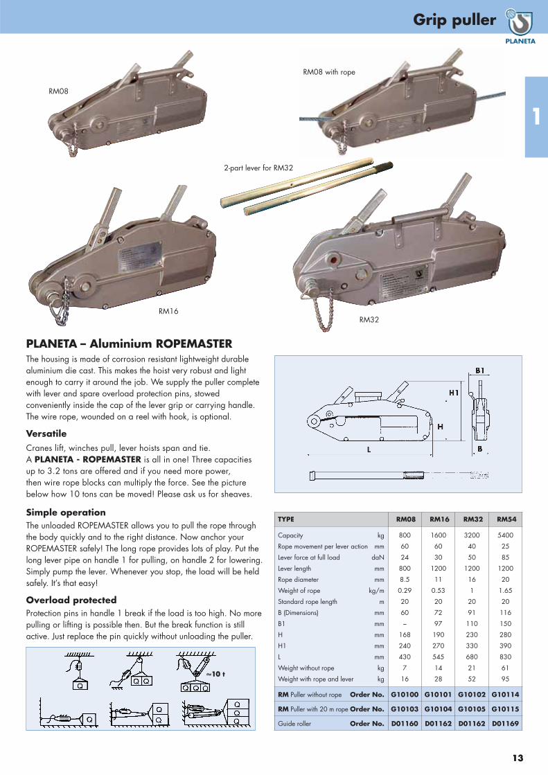
PLANETA – Aluminium ROPEMASTERThe housing is made of corrosion resistant lightweight durable aluminium die cast. This makes the hoist very robust and lightenough to carry it around the job. We supply the puller completewith lever and spare overload protection pins, stowed conveniently inside the cap of the lever grip or carrying handle. The wire rope, wounded on a reel with hook, is optional.
VersatileCranes lift, winches pull, lever hoists span and tie. A PLANETA - ROPEMASTER is all in one! Three capacities up to 3.2 tons are offered and if you need more power, then wire rope blocks can multiply the force. See the picturebelow how 10 tons can be moved! Please ask us for sheaves.
Simple operation The unloaded ROPEMASTER allows you to pull the rope through the body quickly and to the right distance. Now anchor your ROPEMASTER safely! The long rope provides lots of play. Put thelong lever pipe on handle 1 for pulling, on handle 2 for lowering.Simply pump the lever. Whenever you stop, the load will be heldsafely. It’s that easy!
Overload protected Protection pins in handle 1 break if the load is too high. No morepulling or lifting is possible then. But the break function is stillactive. Just replace the pin quickly without unloading the puller.
RM08
RM16RM32
2-part lever for RM32
TYPE RM08 RM16 RM32 RM54
Capacity kg
Rope movement per lever action mm
Lever force at full load daN
Lever length mm
Rope diameter mm
Weight of rope kg/m
Standard rope length m
B (Dimensions) mm
B1 mm
H mm
H1 mm
L mm
Weight without rope kg
Weight with rope and lever kg
800
60
24
800
8.5
0.29
20
60
–
168
240
430
7
16
1600
60
30
1200
11
0.53
20
72
97
190
270
545
14
28
3200
40
50
1200
16
1
20
91
110
230
330
680
21
52
5400
25
85
1200
20
1.65
20
116
150
280
390
830
61
95
RM Puller without rope Order No. G10100 G10101 G10102 G10114
RM Puller with 20 m rope Order No. G10103 G10104 G10105 G10115
Guide roller Order No. D01160 D01162 D01162 D01169
RM08 with rope
��1100 t
1
Trolleys
14
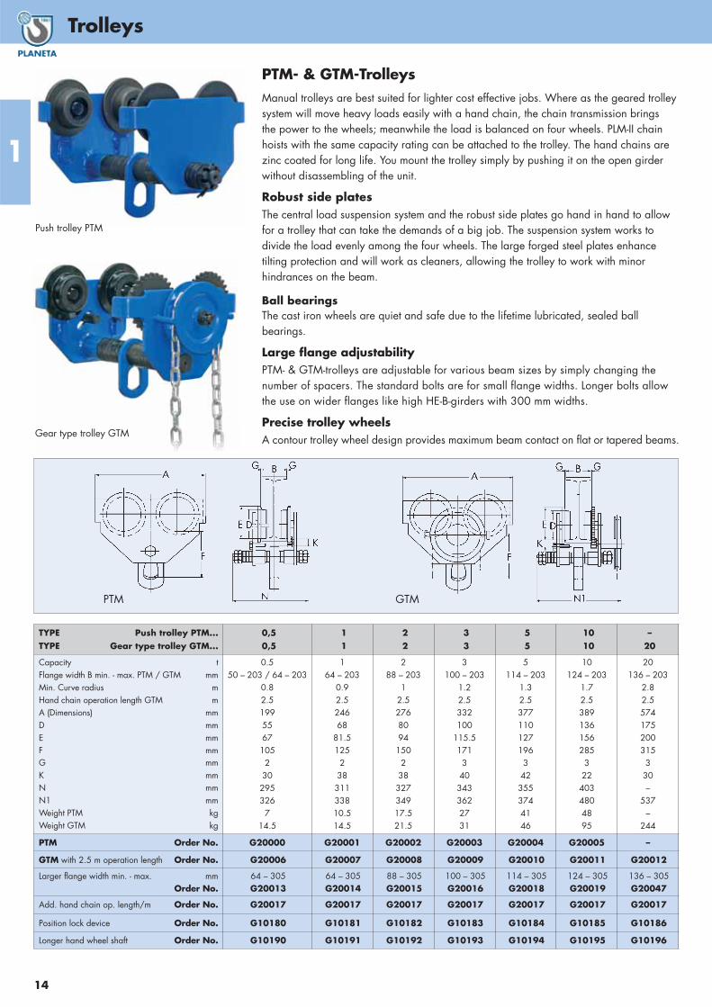
Push trolley PTM
Gear type trolley GTM
PTM- & GTM-TrolleysManual trolleys are best suited for lighter cost effective jobs. Where as the geared trolleysystem will move heavy loads easily with a hand chain, the chain transmission brings the power to the wheels; meanwhile the load is balanced on four wheels. PLM-II chainhoists with the same capacity rating can be attached to the trolley. The hand chains arezinc coated for long life. You mount the trolley simply by pushing it on the open girderwithout disassembling of the unit.
Robust side platesThe central load suspension system and the robust side plates go hand in hand to allowfor a trolley that can take the demands of a big job. The suspension system works todivide the load evenly among the four wheels. The large forged steel plates enhance tilting protection and will work as cleaners, allowing the trolley to work with minorhindrances on the beam.
Ball bearingsThe cast iron wheels are quiet and safe due to the lifetime lubricated, sealed ball bearings.
Large flange adjustabilityPTM- & GTM-trolleys are adjustable for various beam sizes by simply changing thenumber of spacers. The standard bolts are for small flange widths. Longer bolts allowthe use on wider flanges like high HE-B-girders with 300 mm widths.
Precise trolley wheelsA contour trolley wheel design provides maximum beam contact on flat or tapered beams.
TYPE Push trolley PTM...TYPE Gear type trolley GTM...
0,50,5
11
22
33
55
1010
–20
Capacity t Flange width B min. - max. PTM / GTM mmMin. Curve radius mHand chain operation length GTM mA (Dimensions) mmD mmE mmF mmG mmK mmN mmN1 mmWeight PTM kgWeight GTM kg
0.550 – 203 / 64 – 203
0.82.519955671052302953267
14.5
164 – 203
0.92.5 24668
81.512523831133810.514.5
288 – 203
12.5 276809415023832734917.521.5
3100 – 203
1.22.5 332100
115.51713403433622731
5114 – 203
1.32.5 3771101271963423553744146
10124 – 203
1.72.5 3891361562853224034804895
20136 – 203
2.82.5 574175200315330–
537–
244
PTM Order No. G20000 G20001 G20002 G20003 G20004 G20005 –
GTM with 2.5 m operation length Order No. G20006 G20007 G20008 G20009 G20010 G20011 G20012
Larger flange width min. - max. mmOrder No.
64 – 305G20013
64 – 305G20014
88 – 305G20015
100 – 305G20016
114 – 305G20018
124 – 305G20019
136 – 305G20047
Add. hand chain op. length/m Order No. G20017 G20017 G20017 G20017 G20017 G20017 G20017
Position lock device Order No. G10180 G10181 G10182 G10183 G10184 G10185 G10186
Longer hand wheel shaft Order No. G10190 G10191 G10192 G10193 G10194 G10195 G10196
PTM GTM

Seilzuggerät
1
Trolleys
15
Push trolley L87-106
Gear type trolley L87-107
L87-TrolleysL87-trolleys are manufactured in a higher quality for a very rough and unusual use.The chain hoists PREMIUM PRO, PLM-II and PLX-II of the same capacity as the trolley fiteasily into the lugs with their top hook, but these L87-trolleys are best combined withPREMIUM PRO. Trolleys have rubber buffers at both sides!
Ball bearingsThere are life-time lubricated ball bearings of high quality with seals inside the castiron wheels. Their ball shaped surfaces offer a smooth and quiet run on any beam flangeconstruction.
Wide adjustment for any flange widthDiscs of different thicknesses are on the carrying bolts that allow to make the distancebetween side plates shorter or longer by exchanging them from outside to inside.There are two main bolt lengths. The standard bolts are adjustable for normal width.Bolts of size 2 offer more possibilities up to beam flange sizes on HE-B-beams with300 mm width. Prefer this when unclear for what kind of work you will use them.
Double safetyClimb stop on both side of the beam flange hinders the trolley to climb up the beam and prevents from falling down. Right angled side plates work as wheel shaftbreakage protection, falling down protection and beam flange cleaner.
Sturdy side platesThe load is balanced by two carrying bolts on all four wheels because the castle nutstie only one side. This gives the bolts a bit of tolerance for movement and equalizesunproper beam flanges.
More capacities upon request.
L87-106 L87-107
TYPE Push trolley L87-106...TYPE Gear type trolley L87-107...
0,50,5
11
22
33
55
–10
–16
–20
Capacity t Flange width M min. - max. L87-106 and 107 mmMin. curve radius mHand chain operation length L87-107 mA (Dimensions) mmA1 mmB mmC mmD mmE mmH mmJ mmS mmF mmWeight L87-106 kgWeight L87-107 kg
0.550 – 203
0.82.528627219415854797595302610
164 – 203
0.92.5 3033342361966895961103821114
288 – 203
12.5317343268226771081101233821822
3100 – 203
1.22.5 33335732226610013112214440330
34.5
5114 – 203
1.32.5 3553733623011061451421564234447
10124 – 203
1.52.5 –
423442356131176190200453–
88
16136 – 203
3.52.5–
498555498
––
236–
653–
163
20136 – 203
3.52.5–
501555498
––
233–
583–
165
L87-106 Order No. G20100 G20101 G20102 G20103 G20104 – – –
L87-107 w/ 2.5 m operation length Order No. G20105 G20106 G20107 G20108 G20109 G20110 G20176 G20129
Larger flange width min. - max. mmOrder No.
64 – 305G20111
64 – 305G20112
88 – 305G20113
100 – 305G20114
114 – 305G20115
124 – 305G20116
136 – 305G20149
136 – 305G20139
Add. hand chain operation length/m Order No. G20117 G20117 G20117 G20117 G20117 G20117 G20150 G20117

1
Overview of track supports
16
INPNo.
Dimensions (mm) Weightkg/mH B S T
80 80 42 3.9 5.9 6100 100 50 4.5 6.8 8.3120 120 58 5.1 7.7 11.1140 140 66 5.7 8.6 14.3160 160 74 6.3 9.5 17.9180 180 82 6.9 10.4 21.9200 200 90 7.5 11.3 26.2220 220 98 8.1 12.2 31.1240 240 106 8.7 13.1 36.2260 260 113 9.4 14.1 41.9280 280 119 10.1 15.2 48300 300 125 10.8 16.2 54.2320 320 131 11.5 17.3 61340 340 137 12.2 18.3 68360 360 143 13 19.5 76.1380 380 149 13.7 20.5 84400 400 155 14.4 21.6 92.4450 450 170 16.2 24.3 115500 500 185 18 27 141550 550 200 19 30 166
INP-Profile DIN 1025 Bl. 1Profile
Capacity ( t )0.5 1 1.6 2 2.5 3.2 5 6.3 8 10
80100 2.2120 3.1 1.4140 4.1 2.4 1160 5.1 3.7 1.8 1180 6.3 4.6 2.8 1.8 1.1200 7.5 5.6 4 2.8 1.8 1220 8.7 6.6 5.2 4 2.8 1.7240 9.9 7.6 6.2 5.4 3.9 2.7260 11.1 8.7 7.2 6.5 5.2 3.6 1.2280 12.3 9.8 8 7.4 6.7 4.8 2300 13.4 10.9 9.1 8.3 7.5 5.9 2.9 1.7320 14.5 12 10.1 9.3 8.4 7.3 3.9 2.4 1.2340 15.6 13.1 11.1 10.2 9.3 8.2 5 3.3 1.8360 16.6 14.2 12.2 11.3 10.3 9.2 6.3 4.3 2.7 1.4380 15.2 13.2 12.3 11.3 10.2 7.5 5.4 3.5 2400 16.3 14.3 13.3 12.2 11.1 8.8 6.6 4.5 2.8450 16.8 15.8 14.7 13.5 11.3 9.7 7.2 5500 17.1 15.9 13.5 12.2 10.2 7.6550 15.7 14.4 13.1 10.6
Distance between supports in metres
HEBNo.
Dimensions (mm) Weightkg/mH B S T
100 100 100 6 10 20.4120 120 120 6.5 11 26.7140 140 140 7 12 33.7160 160 160 8 13 42.6180 180 180 8.5 14 51.2200 200 200 9 15 61.3220 220 220 9.5 16 71.5240 240 240 10 17 83.2260 260 260 10 17.5 93280 280 280 10.5 18 103300 300 300 11 19 117320 320 300 11.5 20.5 127340 340 300 12 21.5 134360 360 300 12.5 22.5 142400 400 300 13.5 24 155450 450 300 14 26 171500 500 300 14.5 28 187550 550 300 15 29 199600 600 300 15.5 30 212650 650 300 16 31 225
HEB-Profile DIN 1025 Bl. 2
IPENo.
Dimensions (mm) Weightkg/mH B S T
80 80 46 3.8 5.2 6100 100 55 4.1 5.7 8.1120 120 64 4.4 6.3 10.4140 140 73 4.7 6.9 12.9160 160 82 5 7.4 15.8180 180 91 5.3 8 18.8200 200 100 5.6 8.5 22.4220 220 110 5.9 9.2 26.2240 240 120 6.2 9.8 30.7270 270 135 6.6 10.2 36.1300 300 150 7.1 10.7 42.2330 330 160 7.5 11.5 49.1360 360 170 8 12.7 57.1400 400 180 8.6 13.5 66.3450 450 190 9.4 14.6 77.6500 500 200 10.2 16 90.7550 550 210 11.1 17.2 106600 600 220 12 19 122
IPE-Profile DIN 1025 Bl. 5
Track supports as single-rail trolley tracks. Basis of design: DIN 4132 and DIN 15018 B2 H2 (vH = 10 m/min.), including bottom flange deflection (support material: ST 37), bending f= < 1/500 of the distance between supports.
ProfileCapacity ( t )
0.5 1 1.6 2 2.5 3.2 5 6.3 8 10100 3.6 2.6 1.4120 4.9 3.5 2.7 1.8 1.1140 6.2 4.6 3.6 3.1 2.1 1.2160 7.7 5.9 4.7 4.3 3.4 2.2180 9.1 7.1 5.8 5.3 4.7 3.4 1.1200 10.5 8.4 7 6.3 5.7 4.8 2220 11.8 9.7 8.2 7.5 6.8 6 3.1 1.7240 13.1 11 9.4 8.6 7.9 7.1 4.5 2.7 1.2260 14.3 12.3 10.6 9.8 8.9 8.1 5.6 3.6 2.8280 15.4 13.4 11.7 10.9 10 9 6.9 4.6 2.5300 16.6 14.7 13 12.1 11.2 10.2 8.5 6.1 3.7 1.8320 15.7 14 13.1 12.2 11.1 9.3 7.7 5.2 3.1340 16.6 14.9 14 13.1 12 10.1 8.9 6.3 4360 15.8 14.9 14 12.7 10.8 9.8 7.4 5400 16.7 15.7 14.5 12.3 11.2 9.4 6.7450 16.6 14.2 13 11.8 9500 16.1 14.8 13.5 11.5550 16.5 15 13.3600 16.6 15.1650 16.7
Distance between supports in metres
ProfileCapacity ( t )
0.5 1 1.6 2 2.5 3.2 5 6.3 8 1080100 1.8120 3.1 0.7140 4 1.5160 5 2.5180 6.1 3.8 1.3200 7.2 5.3 2.2 1220 8.4 6.3 3.5 2240 9.7 7.4 5 3.2 1.7270 11.4 8.8 6.7 4.5 2.7300 13.1 10.4 8.3 6.3 4 1.8330 14.7 12 9.9 8.5 6 3.5360 16.4 13.6 11.5 10.5 8.6 5.7 1.1400 15.5 13.4 12.3 11.2 8 2.6450 15.6 14.4 13.3 10.9 4.8500 16.6 15.4 13.8 7.7 4.5 1.4550 16 10.6 7 3.5600 14.2 10.4 6.6 3.3
Distance between supports in metres
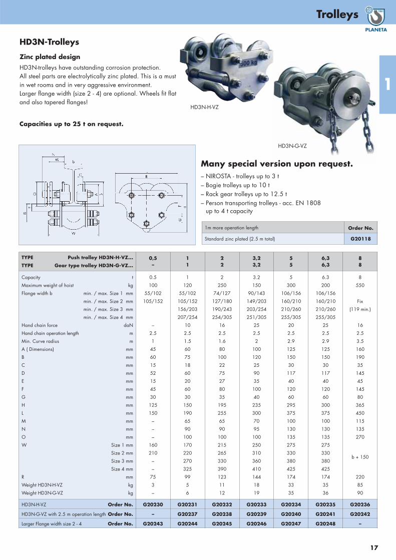
HD3N-Trolleys
Zinc plated design
HD3N-trolleys have outstanding corrosion protection. All steel parts are electrolytically zinc plated. This is a must in wet rooms and in very aggressive environment. Larger flange width (size 2 - 4) are optional. Wheels fit flat and also tapered flanges!
Capacities up to 25 t on request.
HD3N-H-VZ
1m more operation length Order No.
Standard zinc plated (2.5 m total) G20118
TYPE Push trolley HD3N-H-VZ...
TYPE Gear type trolley HD3N-G-VZ...0,5–
11
22
3,23,2
55
6,36,3
88
Capacity t
Maximum weight of hoist kg
Flange width b min. / max. Size 1 mm
min. / max. Size 2 mm
min. / max. Size 3 mm
min. / max. Size 4 mm
Hand chain force daN
Hand chain operation length m
Min. Curve radius m
A ( Dimensions) mm
B mm
C mm
D mm
E mm
F mm
G mm
H mm
L mm
M mm
N mm
O mm
W Size 1 mm
Size 2 mm
Size 3 mm
Size 4 mm
R mm
Weight HD3N-H-VZ kg
Weight HD3N-G-VZ kg
0.5
100
55/102
105/152
–
2.5
1
45
60
15
52
15
45
30
125
150
–
–
–
160
210
–
–
75
3
–
1
120
55/102
105/152
156/203
207/254
10
2.5
1.5
60
75
18
60
20
60
30
150
190
65
90
100
170
220
270
325
99
5
6
2
250
74/127
127/180
190/243
254/305
16
2.5
1.6
80
100
22
75
27
80
35
195
255
65
90
100
215
265
330
390
123
11
12
3.2
150
90/143
149/203
203/254
251/305
25
2.5
2
100
120
25
90
35
100
40
235
300
70
95
100
250
310
360
410
144
18
19
5
300
106/156
160/210
210/260
255/305
20
2.5
2.9
125
150
30
117
40
120
60
295
375
100
130
135
275
330
380
425
174
33
35
6.3
200
106/156
160/210
210/260
255/305
25
2.5
2.9
125
150
30
117
40
120
60
300
375
100
130
135
275
330
380
425
174
35
36
8
550
Fix
(119 min.)
16
2.5
3.5
160
190
35
145
45
145
80
365
450
115
135
270
b + 150
220
85
90
HD3N-H-VZ Order No. G20230 G20231 G20232 G20233 G20234 G20235 G20236
HD3N-G-VZ with 2.5 m operation length Order No. – G20237 G20238 G20239 G20240 G20241 G20242
Larger Flange width size 2 - 4 Order No. G20243 G20244 G20245 G20246 G20247 G20248 –
Many special version upon request.– NIROSTA - trolleys up to 3 t– Bogie trolleys up to 10 t– Rack gear trolleys up to 12.5 t– Person transporting trolleys - acc. EN 1808
up to 4 t capacity
HD3N-G-VZ
1
17
Trolleys

1
Low headroom trolley hoist
18
Combined powerSaving headroom
The very best manual chain hoist PLS PREMIUM and a trolley L87 are puttogether in an integrated combination tosave headroom. That means the distancebetween load point of hook and bottom of beam flange. This is very important if rooms are low or space is narrow.Halls can be build smaller what saves costs.Or if the clearance in older buildings is too narrow for standard hoists - this is the solution!
Advantages of trolley hoist
• shortens downtime in ships• enables low cost bridge cranes• labor saving during repair and
maintenance works.• optimal space utilisation
Low headroom trolleyhoist LHTThe close combination of hoist and trolleywith low headroom offers a unit that isboth functional and versatile. There is lesstime spent messing with equipment andmoney is saved.The LHT-line uses the quality advantagesof the PREMIUM manual chain hoists (see also page 10).
The smoothly moving and operation on ballbearings plus a perfectly finish of surfaceprotection offers the user an uncomparablereliability. The standard equipped overloadprotection fulfills even the high demands onocean going vessels.
Standard version:
• PREMIUM chain hoist with 3 m lift and2.5 m hand chain operation length
• Available as manual push trolley (TYPE -H) or geared trolley (TYPE -G)
• A contour trolley wheel design providesmaximum beam contact on flat or tapered beams. Tilting and climbing protection according CE-regulations areself-evident.
Options (on request):
• Chain case (what is very unusual for manual chain hoists) for down-hanging loose chain that maycause trouble in some cases.
• For corrosive environments, completely zinc plated surfaces are also available for the trolley
• Special non-corrosive and non-sparking steels for chain
Special options Special- Ex-protection with bronze partsand galvanizations, chain collector, overload limiter, beam parking brake.
LHT-H = Chain hoist in push trolley
LHT-G = Chain hoist in gear type trolley
Dimensional drawing LHT-G… (with gear type trolley)
0.5 - 3 t 5 t
10 t 15 t
Low headroom trolley in a special construction withbeam fixing device. It keeps the trolley in position while ship rolls.
LHT-G 010L

TYPE LHT...-H/-G 005L 010L 015L 020L 030L 050L 075L 100L 150L 200L
Capacity t
Standard lift m
Number of chain falls
Chain size mm
Min. headroom (A) mmFlange width M min.-max. (M) mm
Min. curve radius m
Dimension H min. LHT-H mm
Dimension H min. LHT-G mm
B mm
C mm
S mm
Z mm
F mm
Weight with 3 m lift LHT-H kg
Weight with 3 m lift LHT-G kg
0.5
3
1
5 x 15
299
50 - 152
0.85
236
272
258
385
30
7.5
3
15
19
1
3
1
6.3 x 19
331
64 - 203
1
303
334
292
451
37
10.5
3
24
28
1.5
3
1
8 x 24
424
88 - 203
1.1
317
343
358
551
38
12
3
46
44
2
3
1
8 x 24
424
88 - 203
1.1
317
343
358
551
38
12
3
46
44
3
3
1
10 x 28
486
100 - 203
1.3
333
356
434
633
40
14
3
61
65
5
3
2
9 x 27
636
114 - 203
1.4
355
373
448
808
42
15
3
86
91
7.5
3
3
9 x 27
760
124 - 203
2
372
416
628
965
45
16
3
130
135
10
3
4
9 x 27
780
124 - 203
2
378
423
636
990
45
17
3
147
153
15
3
6
9 x 27
930
136 - 203
3.5
449
498
757
1130
56
20
3
278
286
20
3
8
9 x 27
965
136 - 203
3.5
449
498
891
1165
58
25
3
331
353
LHT-H with 3 m lift Order No. G20050 G20051 G20052 G20053 G20054 G20055 G20056 G20057 G20058 G20059
Add. lift / m (LHT-H) Order No. G20070 G20071 G20072 G20073 G20074 G20075 G20076 G20077 G20078 G20079
LHT-G with 3 m lift Order No. G20060 G20061 G20062 G20063 G20064 G20065 G20066 G20067 G20068 G20069
Add. lift / m (LHT-G) Order No. G20080 G20081 G20082 G20083 G20084 G20085 G20086 G20087 G20088 G20089
Larger flange min. - max. mm
width (M) Order No.
50 - 203
G20090
64 - 305
G20091
88 - 305
G20092
88 - 305
G20093
100 - 305
G20094
114 - 305
G20095
124 - 305
G20096
124 - 305
G20097
136 - 305
G20098
136 - 305
G20099
Chain bag * Order No. H10057 H10058 H10058 H10059 H10059 – – – – –
* Flange width to be advised with order! The flange width will be fix and is not adjustable afterwards! Data in chart show only a range of recommendation.
TYPECapacity
tHand force
daNBeam *
mmMin. Headroom
G mmWeight (kg) Order No.
with 3 m liftOrder No.
Add. lift per mcomplete 3 m Meter lift
PKB 10
PKB 20
PKB 32
PKB 60
PKB100
PKB120
1
2
3.2
6
10
12
24
33.5
38
43
40
40
74-300
90-300
106-300
119-300
134-300
134-300
125
150
170
285
270
270
40
120
150
300
400
400
1.7
2
3
5
11
11
G20260
G20261
G20262
G20263
G20275
G20278
G20264
G20265
G20266
G20267
G20276
G20279
TYPEDimensions
Amm
Bmm
Cmm
Emm
Fmm
F1mm
Rmm
Lmm
Nmm
Umm
Omm
nmm
PKB 10
PKB 20
PKB 32
PKB 60
PKB100
PKB120
80
100
125
160
160
160
100
120
150
190
220
220
22
25
30
35
35
35
20
20
26
33
35
35
36
42
48
75
50
50
29
34
39
68
43
43
226
266
310
430
600
600
500
600
685
965
1070
1070
140
145
175
225
223
223
105
150
150
200
196
196
100
135
135
300
300
300
2500
2500
2500
2500
2500
2500
* Chain bag (plastic) up to 3 m lift
1
19
Low headroom trolley hoist
The manual powered PKB is a very compact lifting equipment that combines an integrated chain hoist with a gearedtype trolley. The important fact is that theload hook can be lifted up directly underthe beam flange.
Quality
A solid steel construction with satisfactorilyhoist component.
Standard version
Ball contoured wheels for flat and taperedbeam flanges. High tensile and galvanizedload chain acc. DIN EN 818-7-T. Handchain is also galvanized. Standard lift 3 mand hand chain operating length 2.5 m. Complete with multi-paged operation andtesting manual.
Special options Special- -protection with bronze partsand galvanizations, chain collector, overload limiter, beam parking brake.
Low headroom trolley hoist

1
SUPER-Low combined trolley hoist
20
Lifting and driving by SUPER-LO HPRCompact
The manual powered SUPER-LO HPR is a very compact liftingequipment that combines an integrated chain hoist with a gearedtype trolley. The important fact is that the load hook can be liftedup directly under the beam flange.
No swing of load
This special development of a combined trolley hoist has two liftinggears, one at each side of the girder. They lift the load fullysynchronized with two parallel operating load chains what hindersthe attached load to swing. It is different from other models on the market with only one gear and one chain that goes from onebeam side through the suspension device to the other trolley side.SUPER-LO HPR places your load softly and precisely on the spot.That is an important advantage in machinery rooms of ships i.e.during pulling of motor pistons.
Fast
Lifting is done with very little hand force! The gears have a highratio. It enables SUPER-LO HPR to be your first choice when onlyvery little headroom is available and one man shall do the work!
Quality
It is a solid and robust device made from best steel with machinedsprocket wheels, ball bearing wheels and high tensile load chain.Anti-fall and antirocking systems are included of course.
Standard version
Ball contoured wheels for flat and tapered beam flanges! Standard lift 3 m and hand chain operating length 2.5 m.
Special options Special- Ex-protection with bronze parts and galvanizations, chain collector, overload limiter, beam parking brake.
* Flange width to be advised with order! The flange width will be fix and is not adjustable afterwards! Data in chart show only a range of recommendation.
TYPE
HPR...
Capa-city
t
Handforce
daN
Beam (mm) Min.Curveradius
m
Min.Head-roomH mm
Weight (kg) Dimensions OrderNo.with
3 m lift
OrderNo.
add. liftper m
OrderNo.
Overloadlimiter
Heightmm
Flangewidth* mm
Compl.3 m
Meterlift
Lmm
Pmm
Gmm
Wmm
Umm
Bmm
Emm
Fmm
010
020
040
050
063
080
100
120
150
180
200
240
1
2
4
5
6.3
8
10
12
15
18
20
24
28
28
30
38
41
30
37
45
36
44
36
45
72
72
102
102
157
157
157
157
180
180
180
180
50-300
50-300
82-300
82-300
125-300
125-300
125-300
125-300
125-300
125-300
125-300
125-300
4
4
5
5
10
10
10
10
14
14
14
14
105
152
175
195
220
245
245
280
300
340
340
370
63
70
115
116
260
295
295
305
540
560
580
590
4
5
7
7
8
12
12
12
17
17
21
21
445
445
487
487
755
755
755
755
937
937
937
937
220
220
295
295
490
490
490
490
532
532
532
532
134
134
148
148
208
208
208
208
290
290
290
290
265+b
265+b
295+b
295+b
320+b
320+b
320+b
320+b
505+b
505+b
505+b
505+b
190
190
220
220
350
350
350
350
365
365
365
365
70
70
100
100
155
155
155
155
170
170
170
170
30
30
30
40
40
50
50
58
58
75
75
80
85
85
139
174
174
174
174
192
192
192
192
–
G20200
G20201
G20202
G20203
G20204
G20205
G20206
G20207
G20208
G20209
G20210
G20211
G20212
G20213
G20214
G20215
G20216
G20217
G20218
G20219
G20220
G20221
G20222
G20223
G20224
G20224
G20224
G20225
G20225
G20225
G20225
G20226
G20226
G20226
G20226
G20226

Kurze Kombikatze
21
Beam clamp and trolley
1
TYPE BR... 10 20 30 50
Capacity t
Grip range min. mm
Grip range max. mm
Curve radius m
B min. (Dimensions) mm
D max. mm
E max. mm
J mm
Weight kg
1
64
203
1.1
105
324
340
174
7
2
76
203
1.3
111
387
340
174
20
3
76
203
1.4
127
438
345
280
32
5
100
305
1.5
135
528
465
345
53
BR Order No. F00042 F00036 F00037 F00039
TYPE BK... 10 20 30 50 100
Capacity t
Grip range A min. mm
Grip range A max. mm
B min. (Dimensions) mm
B max. mm
C mm
D mm
E mm
F min. mm
F max. mm
G min. mm
H mm
Weight kg
1
75
230
180
375
80
5
220
102
160
29
20
4
2
75
230
180
375
90
5
220
102
160
28
22
5
3
80
320
220
498
117
8
271
168
240
60
24
9
5
90
320
220
498
127
10
271
168
240
57
30
11
10
90
320
250
514
139
16
280
172
242
55
40
18
BK Order No. F00031 F00032 F00033 F00034 F00035
PLANETA – Beam clamp BK
Type BK
Type BR
Mobile attachment device
The girder clamp BK is a simple and safeload attachment tool. Its easy two-step operation makes it ideal for urgent tasks and assembly jobs. Twist and open the spindle to the width of the beam flange, pushover the flange and close tightly. The clampcan also be used for the lifting and transferof steel beams and as a pulling clamp.See the picture! So they are the ideal tools for erection and installation works asthey fit any beam type. Rapid preparationsare possible for the lifting equipment thatsaves your time and money. No more improvised attachment points! Get safer and reliable with BK!
FeaturesThe frame of the Beam Clamp is made from solid steel plates and the spindle ismade from high tensile galvanized steel that normally forgives a strong tightening.
PLANETA – Trolley BRTrolley BR = clamp on wheels
The grip trolley type BR with its integratedpush trolley is used as a helper for all kindof mounting, assembly and erection work.While the clamp BK is fixed at one place,this attachment point for hoists can travelalong the beam. The system works with the same concept of our PTM trolley with the added bonus, that it can be moved fromone beam to another by a simple and easytwist of the spindle. When it is installed onthe next beam, a crowned counter nut locksthe spindle. Any beam profile type like INP,HE and HE-B can be served. The mechani-cally machined steel rollers and the closedball bearings are permanently lubricated. The spindle is protected against corrosionby zinc galvanization.

1
Manual lifting applications
22

23
2
24
2
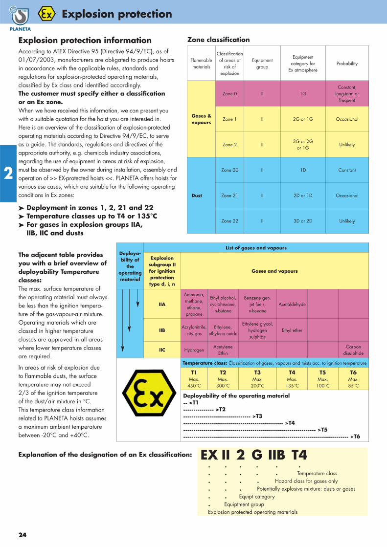
Explosion protection informationAccording to ATEX Directive 95 (Directive 94/9/EC), as of01/07/2003, manufacturers are obligated to produce hoistsin accordance with the applicable rules, standards andregulations for explosion-protected operating materials,classified by Ex class and identified accordingly.The customer must specify either a classification or an Ex zone.When we have received this information, we can present youwith a suitable quotation for the hoist you are interested in. Here is an overview of the classification of explosion-protectedoperating materials according to Directive 94/9/EC, to serve as a guide. The standards, regulations and directives of theappropriate authority, e.g. chemicals industry associations, regarding the use of equipment in areas at risk of explosion,must be observed by the owner during installation, assembly andoperation of >> EX-protected hoists <<. PLANETA offers hoists forvarious use cases, which are suitable for the following operatingconditions in Ex zones:
➤ Deployment in zones 1, 2, 21 and 22➤ Temperature classes up to T4 or 135°C➤ For gases in explosion groups IIA,
IIB, IIC and dusts
Zone classification
The adjacent table providesyou with a brief overview ofdeployability Temperatureclasses:The max. surface temperature ofthe operating material must alwaysbe less than the ignition tempera-ture of the gas-vapour-air mixture.Operating materials which areclassed in higher temperatureclasses are approved in all areaswhere lower temperature classesare required.
In areas at risk of explosion due to flammable dusts, the surfacetemperature may not exceed 2/3 of the ignition temperature of the dust/air mixture in °C. This temperature class informationrelated to PLANETA hoists assumesa maximum ambient temperaturebetween -20°C and +40°C.
Explanation of the designation of an Ex classification: EX II 2 G IIB T4. . . . . .. . . . . Temperature class. . . . Hazard class for gases only. . . Potentially explosive mixture: dusts or gases. . Equipt category. Equiptment groupExplosion protected operating materials
Flammablematerials
Classificationof areas at
risk ofexplosion
Equipmentgroup
Equipmentcategory for
Ex atmosphereProbability
Gases &vapours
Zone 0 II 1GConstant,
long-term orfrequent
Zone 1 II 2G or 1G Occasional
Zone 2 II3G or 2G
or 1GUnlikely
Dust
Zone 20 II 1D Constant
Zone 21 II 2D or 1D Occasional
Zone 22 II 3D or 2D Unlikely
Deploya-bility of
theoperatingmaterial
List of gases and vapours
Explosionsubgroup IIfor ignitionprotectiontype d, i, n
Gases and vapours
IIA
Ammonia,methane,ethane, propane
Ethyl alcohol,cyclohexane,
n-butane
Benzene gen.jet fuels, n-hexane
Acetaldehyde
IIBAcrylonitrile,
city gasEthylene,
ethylene oxide
Ethylene glycol,hydrogensulphide
Ethyl ether
IIC HydrogenAcetylene
EthinCarbon
disulphide
Temperature class: Classification of gases, vapours and mists acc. to ignition temperature
T1Max.
450°C
T2Max.
300°C
T3Max.
200°C
T4Max.
135°C
T5Max.
100°C
T6Max.85°C
Deployability of the operating material -- >T1--------------- >T2--------------------------------- >T3------------------------------------------------- >T4----------------------------------------------------------------- >T5--------------------------------------------------------------------------------- >T6
24
Explosion protection
25
Explosion protection
2
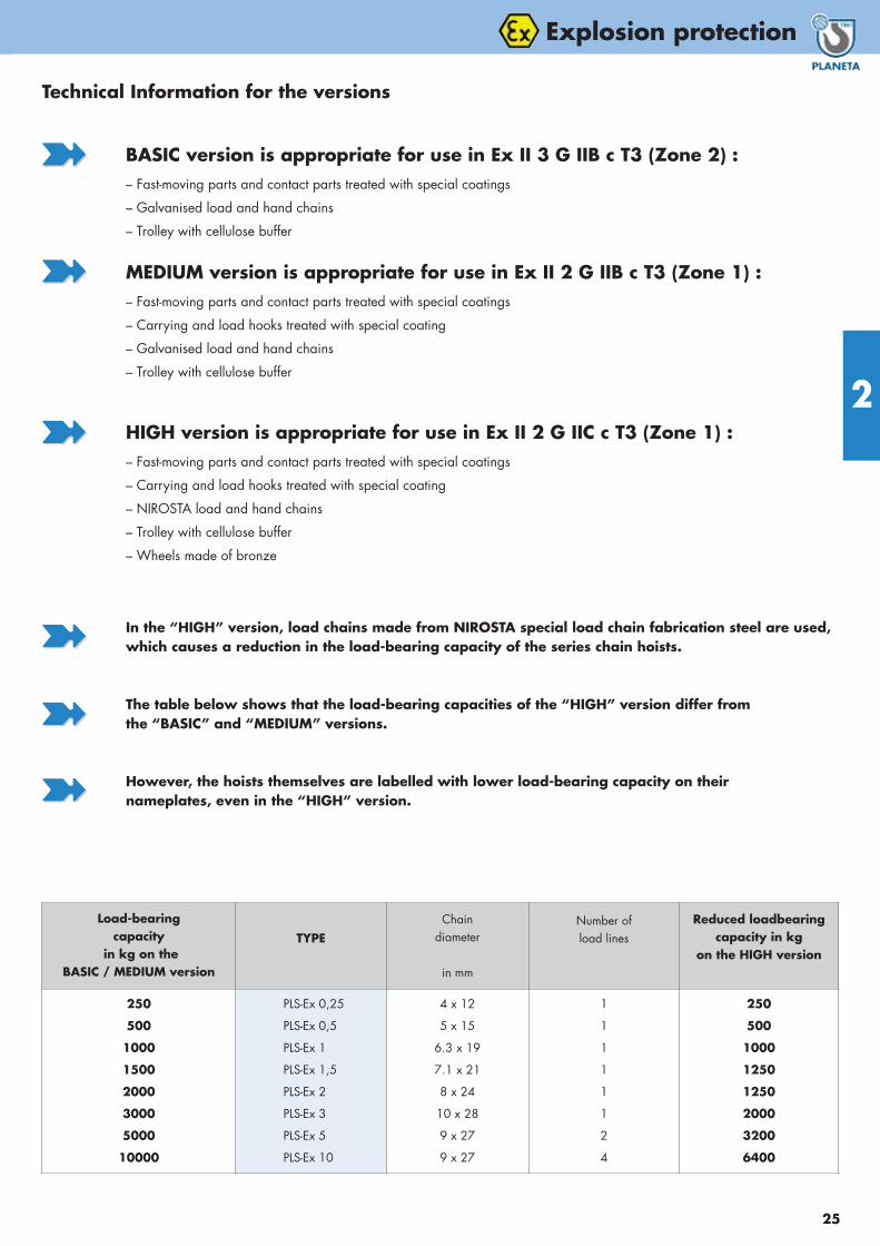
Technical Information for the versions
BASIC version is appropriate for use in Ex II 3 G IIB c T3 (Zone 2) :– Fast-moving parts and contact parts treated with special coatings
– Galvanised load and hand chains
– Trolley with cellulose buffer
MEDIUM version is appropriate for use in Ex II 2 G IIB c T3 (Zone 1) :– Fast-moving parts and contact parts treated with special coatings
– Carrying and load hooks treated with special coating
– Galvanised load and hand chains
– Trolley with cellulose buffer
HIGH version is appropriate for use in Ex II 2 G IIC c T3 (Zone 1) :– Fast-moving parts and contact parts treated with special coatings
– Carrying and load hooks treated with special coating
– NIROSTA load and hand chains
– Trolley with cellulose buffer
– Wheels made of bronze
Load-bearing capacity
in kg on the BASIC / MEDIUM version
TYPEChain
diameter
in mm
Number ofload lines
Reduced loadbearingcapacity in kg
on the HIGH version
250
500
1000
1500
2000
3000
5000
10000
PLS-Ex 0,25
PLS-Ex 0,5
PLS-Ex 1
PLS-Ex 1,5
PLS-Ex 2
PLS-Ex 3
PLS-Ex 5
PLS-Ex 10
4 x 12
5 x 15
6.3 x 19
7.1 x 21
8 x 24
10 x 28
9 x 27
9 x 27
1
1
1
1
1
1
2
4
250
500
1000
1250
1250
2000
3200
6400
In the “HIGH” version, load chains made from NIROSTA special load chain fabrication steel are used,which causes a reduction in the load-bearing capacity of the series chain hoists.
The table below shows that the load-bearing capacities of the “HIGH” version differ fromthe “BASIC” and “MEDIUM” versions.
However, the hoists themselves are labelled with lower load-bearing capacity on theirnameplates, even in the “HIGH” version.
��
��
��
��
��
��

26
2
-proof manual chain hoists
PLS EX
PLS PREMIUM with EX-protectionThe PLS PREMIUM-EX gets a very special surface treatment and has some changes in design that allows you to use the manual chain hoistin explosion hazardous areas. It accords to EC-guide lines 94/9/EG (ATEX-standards).
Three explosion clases are specified. We offer the versions Basic, Medium and High. Please ask us for more detailed informations in case of doubts.
All around galvanization and chromatationMud and dirt cannot harm this hoist! This protection begins with self-locking galvanized castle nuts, goes over bronze wheels and rustfree chains and ends with fully chromated housing parts. Overload protectionin 0.5 t capacity hoist and bigger, supplied with ATEX-Certificate!
1 m more operation length Capacity Order No.
Hand chain Basic/Medium
Hand chain High
0.5 - 10 t
0.5 - 10 t
G50032
G50033
0.25 – 3 t 5 t 10 t
TYPE PLS-EX... PLS PREMIUM with EX-protection – Versions Basic/Medium/High
Capacity Basic/Medium t
Capacity High t
0.25
0.25
0.5
0.5
1
1
1.5
1.25
2
1.25
3
2
5
3.2
10
6.4
Hand chain force daN
Hand chain operation length m
Number of chain falls
Chain size mm
Min. Headroom (A) mm
B (Dimensions) mm
C mm
D mm
E mm
N m
F mm
F1 mm
Weight with standard lift kg
Weight per m additional lift kg
12
2.5
1
4 x 12
270
47
69
52
65
2.5
30
20
6
1
25
2.5
1
5 x 15
350
49
89
50
96
2.5
30
23
10
1.2
28
2.5
1
6.3 x 19
383
59
95
63
98
2.5
40
27
12
1.5
31
2.5
1
7.1 x 21
442
76
100
75
107
2.5
45
33
17
1.7
29
2.5
1
8 x 24
485
77
100
87
115
2.5
50
35
19
2
37
2.5
1
10 x 28
554
85
120
105
150
2.5
55
39
35
2.8
37
2.5
2
9 x 27
688
89
100
90
160
2.5
65
45
41
3
38
2.5
4
9 x 27
765
89
100
150
310
2.5
75
54
78
4.2
Version Basic:
PLS-EX with 3 m liftOrder No. G50000 G50001 G50002 G50003 G50004 G50005 G50006 G50007
Version Medium:
PLS-EX mit 3 m liftOrder No. G50008 G50009 G50010 G50011 G50012 G50013 G50014 G50015
Add. lifting height per m
Basic / MediumOrder No. G10048 G10049 G10050 G10051 G10052 G10053 G10054 G10055
Version High:
PLS-EX with 3 m liftOrder No. G50016 G50017 G50018 G50019 G50020 G50021 G50022 G50023
Add. lifting height per m
HighOrder No. G50024 G50025 G50026 G50027 G50028 G50029 G50030 G50031
Chain bag up to 3 m lift* Order No. H10057 H10057 H10058 H10058 H10059 H10059 – –
* Chain bag (plastic) up to 3 m lift. Chain bag up 6 t (steel plate) on request.

27
-proof applications
2
28
2
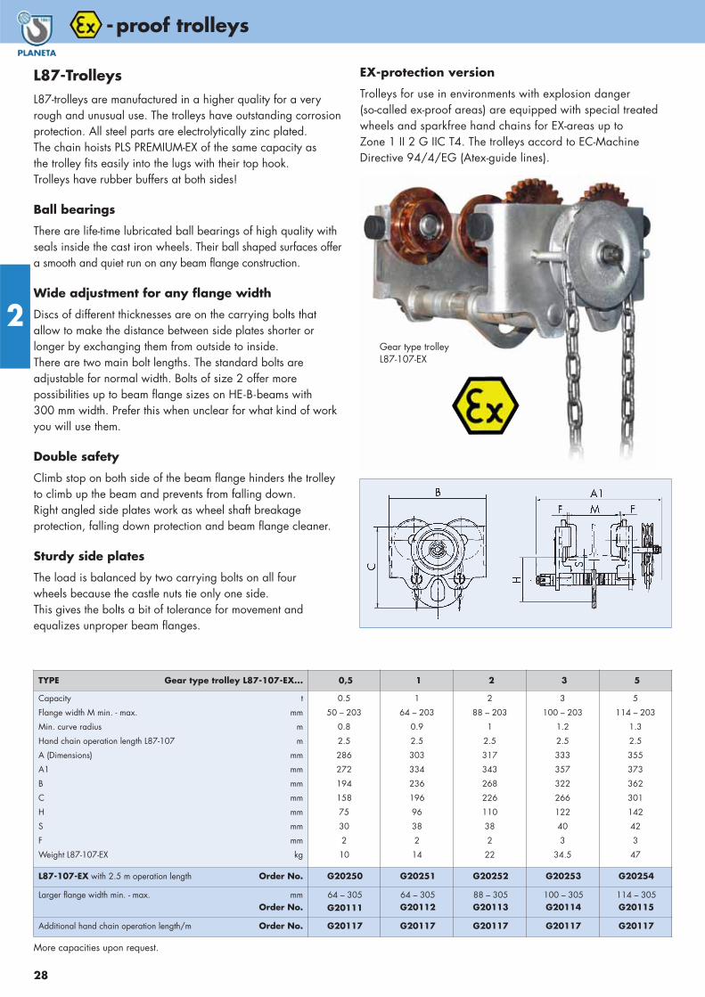
-proof trolleys
L87-TrolleysL87-trolleys are manufactured in a higher quality for a veryrough and unusual use. The trolleys have outstanding corrosionprotection. All steel parts are electrolytically zinc plated. The chain hoists PLS PREMIUM-EX of the same capacity as the trolley fits easily into the lugs with their top hook. Trolleys have rubber buffers at both sides!
Ball bearings
There are life-time lubricated ball bearings of high quality withseals inside the cast iron wheels. Their ball shaped surfaces offera smooth and quiet run on any beam flange construction.
Wide adjustment for any flange width
Discs of different thicknesses are on the carrying bolts thatallow to make the distance between side plates shorter or longer by exchanging them from outside to inside. There are two main bolt lengths. The standard bolts are adjustable for normal width. Bolts of size 2 offer more possibilities up to beam flange sizes on HE-B-beams with 300 mm width. Prefer this when unclear for what kind of workyou will use them.
Double safety
Climb stop on both side of the beam flange hinders the trolleyto climb up the beam and prevents from falling down. Right angled side plates work as wheel shaft breakage protection, falling down protection and beam flange cleaner.
Sturdy side plates
The load is balanced by two carrying bolts on all four wheels because the castle nuts tie only one side. This gives the bolts a bit of tolerance for movement and equalizes unproper beam flanges.
EX-protection version
Trolleys for use in environments with explosion danger (so-called ex-proof areas) are equipped with special treatedwheels and sparkfree hand chains for EX-areas up to Zone 1 II 2 G IIC T4. The trolleys accord to EC-Machine Directive 94/4/EG (Atex-guide lines).
TYPE Gear type trolley L87-107-EX... 0,5 1 2 3 5
Capacity t
Flange width M min. - max. mm
Min. curve radius m
Hand chain operation length L87-107 m
A (Dimensions) mm
A1 mm
B mm
C mm
H mm
S mm
F mm
Weight L87-107-EX kg
0.5
50 – 203
0.8
2.5
286
272
194
158
75
30
2
10
1
64 – 203
0.9
2.5
303
334
236
196
96
38
2
14
2
88 – 203
1
2.5
317
343
268
226
110
38
2
22
3
100 – 203
1.2
2.5
333
357
322
266
122
40
3
34.5
5
114 – 203
1.3
2.5
355
373
362
301
142
42
3
47
L87-107-EX with 2.5 m operation length Order No. G20250 G20251 G20252 G20253 G20254
Larger flange width min. - max. mmOrder No.
64 – 305G20111
64 – 305G20112
88 – 305G20113
100 – 305G20114
114 – 305G20115
Additional hand chain operation length/m Order No. G20117 G20117 G20117 G20117 G20117
More capacities upon request.
Gear type trolley L87-107-EX

29
-proof trolleys
2
SUPER-Corrosion protection (Basic/Medium)HD3N-trolleys have outstanding corrosion protection. All steel parts areelectrolytically zinc plated. This is a must in wet rooms and in veryaggressive environment. Larger flange width (size 2 - 4) are optional.Wheels fit flat and also tapered flanges!
Capacities up to 25 t on request.
EX-protection version (High)Trolleys for use in environments with explosion danger (so-called ex-proof areas) are equipped with bronze wheels and sparkfree handchains for EX-areas up to Zone 1 II 2 G IIC T4. The trolleys accord to EC-Machine Directive 94/4/EG(Atex-guide lines).
Many special version upon request.
HD3N-H
HD3N-G-EX
Die Laufkatzenpreise verstehen sich für Flanschbreitenbereich 1 bzw. Festmaß ab 8 t. Preise für Sonderausführungen und Optionen auf Anfrage.
1m more operation length Order No.
Standard zinc plated (2.5 m total)V2A (EX) rustfree (2.5 m total)
G20118G20119
– Person transportingtrolleys - acc. EN 1808 up to 4 t capacity
– Flame zinc plating– NIROSTA - trolleys up to 3 t (non-corrosive steel)
TYPE Push trolley HD3N-H...TYPE Gear type trolley HD3N-G...
0,5–
11
22
3,23,2
55
6,36,3
88
1010
12,512,5
Capacity tMaximum weight of hoist kgFlange width b min. / max. Size 1 mm
min. / max. Size 2 mmmin. / max. Size 3 mmmin. / max. Size 4 mm
Hand chain force daNHand chain operation length mMin. Curve radius mA (Dimensions) mmB mmC mmD mmE mmF mmG mmH mmL mmM mmN mmO mmW Size 1 mm
Size 2 mmSize 3 mmSize 4 mm
R mmWeight HD3N-H kgWeight HD3N-G kg
0.5100
55/102105/152
–2.51
45601552154530
125150
–––
160210
––
753–
1120
55/102105/152156/203207/254
102.51.560751860206030
1501906590
1001702202703259956
2250
74/127127/180190/243254/305
162.51.680
1002275278035
1952556590
1002152653303901231112
3.2150
90/143149/203203/254251/305
202.52
100120259035
10040
2353007095
1002503103604101441819
5300
106/156160/210210/260255/305
202.52.912515030
11740
12060
2953751001301352753303804251743335
6.3200
106/156160/210210/260255/305
252.52.912515030
11740
12060
3003751001301352753303804251743536
8550
Fix(119 min.)
162.53.516019035
14545
14580
365450115135270
b + 150
2208590
10600
Fix(131 min.)
192.53.516019035
14545
14580
370450115135270
b + 150
2209095
12.5150
Fix(143 min.)
232.53.516019035
14545
14580
375450115135270
b + 150
22095
100
Version Basic/MediumHD3N-H
Order No. G20120 G20121 G20122 G20123 G20124 G20125 G20126 G20127 G20128
Version HighHD3N-H
Order No. G20130 G20131 G20132 G20133 G20134 G20135 G20136 G20137 G20138
Version Basic/MediumHD3N-G with 2.5 m operation length
Order No. – G20141 G20142 G20143 G20144 G20145 G20146 G20147 G20148
Version HighHD3N-G with 2.5 m operation length
Order No. – G20151 G20152 G20153 G20154 G20155 G20156 G20157 G20158
Larger Flange width size 2 - 4 Order No. G20160 G20161 G20162 G20163 G20164 G20165 – – –
Flame zinc plating Order No. G20170 G20171 G20172 G20173 G20174 G20175 G20179 G20177 G20178
HD3N-G

Air chain hoists
2
30
Pneumatic air chainhoist LIFTMASTER TCRThe air chain hoist, why?A hoist cannot be selected solely on the basis of its lifting capacity. Ease ofoperation, environment, intended use,frequency of use and degree of speedcontrol are important factors that need to be considered. The drivingforce behind increased use of the LIFT-MASTER in the industrial market placeis that a growing number of industriesare simply finding the many inherentadvantages of the LIFTMASTER.
EnvironmentThe air chain hoist LIFTMASTER can be operated in explosive atmospheresand corrosive environments, becausethe air motor is inherently spark resistant and also extremely resistant to adverse external conditions.
Reliable, trouble freeOverloading will not damage the motor because there is an automatic switch-off over 1 t capacity. Whetheryou are faced with constant stop-startor continuous operation, you canexpect reliable performance.
Variable speed controlInfinitely variable speed control allowsfor accurate and precise load position-ing. You can inch loads into position orincrease the speed when accuracy is ofless importance.
Smooth starts & stopsImportant for operator safety as well as for reducing parts wear andmaintenance. Smoother operation leadsto less vibration, less stress on partsand a longer unit life.
Compact & lightweightSmall external dimensions and a light-weight construction make the LIFT-MASTER hoist ideal for close head roomsituations and temporary installations.
Very economicalApproximately 1/3 of the cost of a wire-rope hoist of the same capacity withsame features.
StandardHeight of lift 3 m, Control length 2 m, use up to EX-Zone IIA 3 GD c T4/T5/T6.
TCR 3000Pwith Pendant control
TCR 1000C2with Rope control
Chain bag up 6 t (steel plate) on request.
In compliance with EX-Zone - ClassesEN 50 014 and newest EC-Machinery Directive 94/4/EG (ATEX- guide lines).
TYPE Order No.
Add. control length rope control / mAdd. control length pendant control / m
H10042H10043
Pneumatic-Special-Oil Order No.
Content: 2.5 Liter H20566
TYPE LIFTMASTER TCR... 250C/P 500C/P 1000C2/P 1000C/P 2000C2/P 3000C/P
Capacity (Air pressure 6 bar - 1Bm) tLifting speed without load m/minLifting speed with full load m/minLowering speed without load m/minLowering speed with full load m/minAir consumption with full load l/secNumber of chain fallsAir inlet R inchChain size (diameter) mmWeight with standard lift kg
0.2520.510.513.417.9251
1/2”6.3 x 19.1
31
0.520.510.513.417.9251
1/2”6.3 x 19.1
31
110.35.36.79
252
1/2”6.3 x 19.1
34
111.3
66.8
10.3251
1/2”7.1 x 21
35
25.73
3.45.2252
1/2”7.1 x 21
40
35.42.83.34.6331
1/2”11.2 x 34
69
TCR... with 3 m Lift with rope control Order No. H10001 H10002 H10003 H10004 H10005 H10006
TCR... with 3 m Lift with pendant control Order No. H10015 H10016 H10017 H10018 H10019 H10020
Add. lift per meter Order No. H10029 H10029 H10030 H10031 H10032 H10033
Maintenance unit Order No. H10054 H10054 H10054 H10054 H10054 H10055
Add. air powered trolley DLK Order No. H10044 H10044 H10044 H10044 H10045 H10046
Chain bag (plastic) to 3 m lift Order No. H10057 H10057 H10058 H10058 H10058 H10059
TYPE LIFTMASTER TCR... 6-C2/P2 10-C2/P2 12-C4/P4 15-C5/P5 20-C4/P4 25-C2/P2
Capacity (Air pressure 6 bar - 1Bm) tLifting speed without load m/minLifting speed with full load m/minLowering speed without load m/minLowering speed with full load m/minAir consumption with full load l/secNumber of chain fallsAir inlet R inchChain size (diameter) mmWeight with standard lift kg
62.71.41.72.3332
1/2”11.2 x 34
90
102.21.51.82.39021”
16 x 45190
121.40.70.81.2334
1/2”11.2 x 34
170
151.10.60.70.9335
1/2”11.2 x 34
221
201.20.80.91.29041”
16 x 45470
250.70.50.50.7120
21”
22 x 66320
TCR... with 3 m Lift with rope control Order No. H10007 H10008 H10009 H10010 H10011 H10012
TCR... with 3 m Lift with pendant control Order No. H10021 H10022 H10023 H10024 H10025 H10026
Add. lift per meter Order No. H10034 H10035 H10036 H10037 H10038 H10039
Maintenance unit Order No. H10055 H10055 H10055 H10055 H10056 H10056
Add. air powered trolley DLKOrder No. H10047 H10048 H10049 H10049 H10050 H10051

31
Air chain hoists
2
Air powered trolley DLK
10 t
25 t
TYPE TCR... A B C D E H
TCR 250 C/PTCR 500 C/PTCR 1000 C2/P2TCR 1000 C/PTCR 2000 C2/P2TCR 3000 C/P
342342342342342449
156156156156156202
149149180157194245
525247405047
292929292934
462462519466580580
TYPE TCR... A B C D E H
TCR 6 C2/P2TCR 10 C2/P2TCR 12 C4/P5TCR 15 C5/P5TCR 20 C4/P4TCR 25 C2/P2
449560441441549710
202247191191247335
275445520480230478
63165210210200165
42405783
10080
690890900900
13501440
1- chain fall 2 - chain falls
Air pressure
The LIFTMASTER hoist reaches itsnominated performance data at 6 barflowing air pressure. But it can operatealso with only 4 or 5 bar, which decreasesthe lifting speed by 20 to 30 percent. The SWL will still be lifted. The type seriesTCR has a wide capacity spectrum from250 kg up to 100 tons upon request. Allhoists have an excellent relation betweenprice and performance. They are infinitelyadjustable in lifting and lowering speedand can work continuously. The pull chaincontrol is even better in speed regulationthan the push key control because it works directly on the inside main valve.The TCR is also avaible with specialchains from sparkproof material andhooks can be treated with bronze plating. Please ask for our assistance to choose the correct option.
Air powered trolley
There are air powered and gear typetrolleys available for all capacities of LIFTMASTER. Please inquire!
Hoists in trolley on request!
Drop forged, high tensile Top Hook made of tempered steel
Rigid, zinc galvanized Hook Safety Latch
Efficient Muffler
Precise Chain Guide with chain stripper
Dependable starting Vane Motor with 7 vanes
Control Valve, for smoothlyadjustable speed control
Robust cast steel Housing
Sprocket wheel with perfectly fitting milled pockets
Limit Switches for highest andlowest hook position, also control lever for chain control
Round link steel chain acc. DIN EN 818-7-T with Galvanized Protection
Flexible Control hoses
Automatic Disc Brake
Three-stage Planetary Gearing
Emergency-Stop-Button, also for 4-key-control with trolley, according EN 418.
Swivel Hook in axial ball bearing
TCR 3000P

32
Air chain hoists
2
TCRM 250DP(Pendant control)
LightVery light weightedaluminium housing
FastLifting speed from 4.5 to17 m/min with full load
TYPE TCR... M125 C/DP M250 C/DP M500 C2/DP2 TCS-500 TCS-980*
Capacity kg
Number of chain falls
Air pressure bar
Lifting speed with full load m/min
Lifting speed without load m/min
Air consumption l/s
Chain dimensions mm
Control length m
Min. Headroom (H) mm
A (Dimensions) mm
B mm
C mm
D mm
G mm
K mm
L mm
S mm
T mm
Weight with standard lift kg
Weight for 1 m additional lift kg
125
1
6
14
19
11.7
4 x 12
2
305
230
110
120
95
130
29
15
35
60
7
0.35
250
1
6
9.3
19
11.7
4 x 12
2
305
230
110
120
95
130
29
15
35
60
7
0.35
500
2
6
4.5
9.5
11.7
4 x 12
2
365
230
110
120
95
130
29
15
35
60
8.5
0.7
500
1
6
17
33
33
6.3 x 19
2
414
365
204
161
143
151
25
15
31
112
15.9
0.9
990
2
6
8.5
16.5
33
6.3 x 19
2
456
365
204
161
173
173
29
29.5
37
136
16.8
1.8
TCR/TCS...with 3 m lift and rope control Order No. H10070 H10071 H10072 H10088 H10108
TCR/TCS...with 3 m lift and pendant control Order No. H10073 H10074 H10075 H10098 H10118
Additional lift per meter Order No. H10076 H10076 H10077 H10069 H10128
TCS-980 with
chain case
TCRM 250C(Rope control)
TCS-500 high preciselyspeed control
* Equipped with chain case up to 4 m lifting height.
Chain-case for TYPE
Size of chain case
OrderNo.
TCRM 125
up to 12 m chain H10354
up to 20 m chain H10355
TCRM 250
up to 12 m chain H10354
up to 20 m chain H10355
TCRM 500
up to 6 m chain H10354
up to 10 m chain H10355
Chain bagfor TCRM
Mini-Hoist TCRM/TCSIf you are looking for an excellent technical, flexible and compactair hoist that works under many different situations, now here it is. The new model range TC. This series comprises the new 125 to990 kg pneumatic chain hoists. The TC is one of the most compactand transportable air chain hoist you can get. The headroom of theTC hoist is only 305 mm (125/250 kg). Although the weight isonly 7 kg with inclusive 3 m length of load chain, the air hoist canlift up to 17 meters per minute without any problem. The new TC is available with rope or pendant control includingemergency stop. The keys allow optimal control over variablespeeds.

33
Small air rope hoists
2
Air rope hoist LIFTMASTER EHW Mobile application
The pneumatic rope hoist LIFTMASTER EHW is a practical additionto the TC chain hoist program. This model is ideal for small loadup to 140 KG that must be moved quite often. All hoists are equipped with a high-tensile steel rope which is spooled on a druminside of the hoist body. Only up to Ex II 2 G D II B T 5 (X).
Two types of controlThe EHW types are hand guided and have their control direct at the hoist body that allows one hand of operator to be free forother actions. The EHW-R hoists have a separate push key pendant control with one red emergency shut-off mushroom buttonthat ensures safety and complies with CE-regulations.
Automatic Brake
All hoists have a fail-safe automatic disc brake which holds theload in any position even if the air supply fails.
Versatility of Service
These hoist are perfectly used at pack tables, for lifting of barrels,bundles, parcels, over machine tools in slewing cranes etc. The hoists switch off automaticaly in highest and lowest hookposition. Interesting is the combination with a pneumatic vacuumlifter, whereby both units can be served through one common air line. All hoists have a standard 2-meter rope which fits onto the drum.
That is sufficient in most cases. However if you need a longerrope, perhaps to allow a higher suspension of the type EHW-R,we can extend the rope. But this additional length cannot bespooled on the drum. The control hoses can be made longer upto 10 m. The air pressure shall be max. 6.3 bar, but it can dropto 4 bar and the hoist still lifts its rated capacity, only muchslower.
EHW60/120 EHW60R/120R
EHW120REHW60
TYPE EHW60 EHW60R EHW120 EHW120R
Capacity kg
Standard lift m
Number of rope strands
Air pressure bar
Lifting speed with full load 0 - m/min
Air consumption m3/min
Air inlet R inch
Weight with standard lift kg
60
2
1
6
26
0.9
3/8”
9
60
2
1
6
26
0.9
3/8”
10
120
2
1
6
16
0.9
3/8”
9
120
2
1
6
16
0.9
3/8”
10
EHW... with standard rope length Order No. H10080 H10083 H10081 H10084
Longer control hoses per meter Order No. – H10086 – H10086
More capacities on request.

34
Air supply
2
TYPE 1: Spiral hoseBeam length up to 10 m are best to serve with a spiral hose for air supply. A rope is spanned parallel to the beam between twoholding arms. The spiral hose winds around it. The plastic hoseacts like a spiral spring, gets longer or shorter with the moving trolley.
Complete set for 3 meter beam drive:Spiral hose with reserve (1.7 x L), twistable connections with malethread, 2 span arms, wire rope with reserve, 4 rope clamps and 2 span screws. The maintenance unit (filter, lubricator, regulator)shoud be fixed as near as possible to the trolley. Short beams mayhave it at the beginning of the beam.
TYPE 2: Drag hosePulling the air hose behind the trolley is the easiest way to bringair to the hoist. Small plastic trolleys carry the hose in certain distance behind the trolley. The hose hangs normally one meterdown. So one hose carrier is needed each two meters. The hose istransparent with a strengthening textile inlet. It stands a pressure upto 15 bar. Water and oil cannot harm it. Since the trolleys are pushed together when the train comes into end position, the beammust be a little bit longer.
Complete setThe beside mentioned order number includes all accessory for abeam length of 3 m. In details: air hose plus 3 meter addition forleading down to the ground where a ball valve cuts air supply off.Plastic trolleys, end clamp, nipples end other fittings. If the hoseshall be detachable, a quick-acting coupling shall be ordered.
ATTENTION:Driving through curves need special equipment. Please inquire!
TYPE 3: C-trackA C-track is the most comfortable air supply. The total beam lengthcan be used for driving. This type is mostly used with slewingcranes because the complete length of swing arm is necessary todrive on. Here the holding arm of C-rack can be fixed easily what is
difficult in opposite under the ceiling in case of a double T-beam. C-tracks are available in lengths of 6 m. They are added with combiners to longer rails.
Complete setThe beside mentioned order number includes all accessory for abeam length of 3 m. In details: air hose plus 3 meter addition forleading down to the ground, where a ball valve cuts air supply off.Three holding arms, connection clamps, screws, C-rail holder, C-rails in 2 m length, C-rail connectors, first trolley leading arm,hose clamps, fittings.All metal parts are zinc plated. Remind when ordering that hoses have the correct diameter. Choose one size bigger in case that hoses are longer than 10 m. The longer the hose, the deeper the pressure drops. Hoists need minimum 5 bar FLOWING pressure during operation. Each quick-acting coupling, every pipe bow, all valves etc. reduce flow pressure. Even when static pressure is 6 bar before operation, the flow pressure is a result of air friction in hoses andfittings and other users of the same ring pipe line. Keep an eye on your pressure gauge! A bad performance of air hoist is for99% a result of wrong air supply and too low flow pressure.
TYPE 1
TYPE 2
TYPE 3
Ball valve Quick-action coupling
TYPE 1 2 3
Standard driving length m
Complete 1/2 inch Order No.
3
H10180
3
H10181
3
H10182
1 m more rail length 1/2 inch Order No. H10183 H10184 H10185
Complete 3/4 inch Order No. H10186 H10187 H10188
1 m more rail length 3/4 inch Order No. H10189 H10190 H10191
Complete 1 inch Order No. – H10193 H10194
1 m more rail length 1 inch Order No. – H10196 H10197
Special equipment:
Quick-action coupling 1/2 inch Order No. – H10199 H10200
Quick-action coupling 3/4 inch Order No. – H10202 H10203
Quick-action coupling 1 inch Order No. – H10205 H10206
Air hose 1/2 inch - 6 bar Order No. – H10208 H10209
Air hose 3/4 inch - 6 bar Order No. – H10211 H10212
Air hose 1 inch - 6 bar Order No. – H10214 H10215
Air hose 11/4 inch - 6 bar Order No. – H10217 H10218
Air hose 11/2 inch - 6 bar Order No. – H10220 H10221

35
3
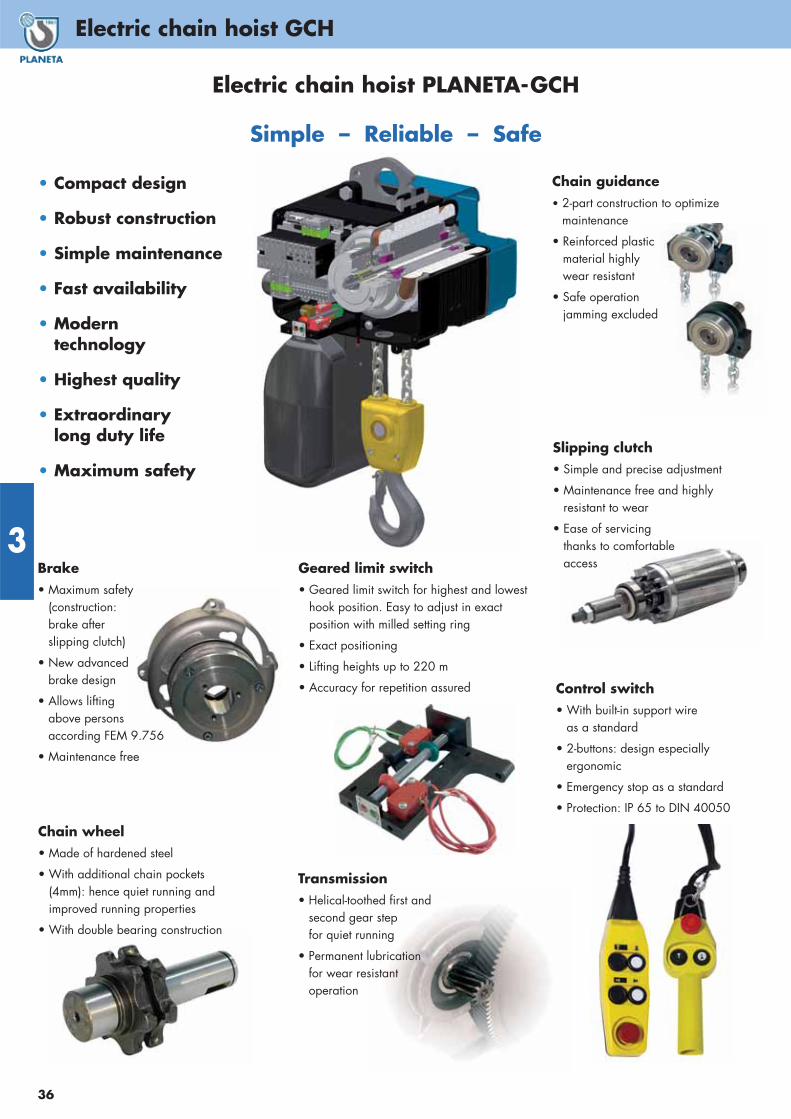
3
36
Electric chain hoist GCH
Brake• Maximum safety
(construction: brake after slipping clutch)
• New advancedbrake design
• Allows lifting above persons according FEM 9.756
• Maintenance free
Transmission• Helical-toothed first and
second gear stepfor quiet running
• Permanent lubricationfor wear resistantoperation
Chain wheel• Made of hardened steel
• With additional chain pockets(4mm): hence quiet running andimproved running properties
• With double bearing construction
Geared limit switch • Geared limit switch for highest and lowest
hook position. Easy to adjust in exactposition with milled setting ring
• Exact positioning
• Lifting heights up to 220 m
• Accuracy for repetition assured
Chain guidance• 2-part construction to optimize
maintenance
• Reinforced plastic material highly wear resistant
• Safe operationjamming excluded
Slipping clutch• Simple and precise adjustment
• Maintenance free and highly resistant to wear
• Ease of servicingthanks to comfortableaccess
Control switch• With built-in support wire
as a standard
• 2-buttons: design especially ergonomic
• Emergency stop as a standard
• Protection: IP 65 to DIN 40050
Electric chain hoist PLANETA-GCH
Simple – Reliable – Safe
• Compact design
• Robust construction
• Simple maintenance
• Fast availability
• Modern technology
• Highest quality
• Extraordinary long duty life
• Maximum safety
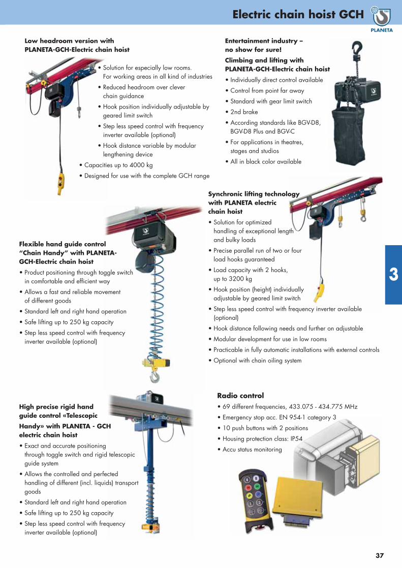
37
Electric chain hoist GCH
3
Entertainment industry –no show for sure!
Climbing and lifting with PLANETA-GCH-Electric chain hoist
• Individually direct control available
• Control from point far away
• Standard with gear limit switch
• 2nd brake
• According standards like BGV-D8, BGV-D8 Plus and BGV-C
• For applications in theatres, stages and studios
• All in black color available
Synchronic lifting technology with PLANETA electric chain hoist
• Solution for optimized handling of exceptional length and bulky loads
• Precise parallel run of two or fourload hooks guaranteed
• Load capacity with 2 hooks, up to 3200 kg
• Hook position (height) individuallyadjustable by geared limit switch
• Step less speed control with frequency inverter available (optional)
• Hook distance following needs and further on adjustable
• Modular development for use in low rooms
• Practicable in fully automatic installations with external controls
• Optional with chain oiling system
Flexible hand guide control“Chain Handy” with PLANETA-GCH-Electric chain hoist
• Product positioning through toggle switchin comfortable and efficient way
• Allows a fast and reliable movement of different goods
• Standard left and right hand operation
• Safe lifting up to 250 kg capacity
• Step less speed control with frequency inverter available (optional)
Low headroom version withPLANETA-GCH-Electric chain hoist
• Solution for especially low rooms. For working areas in all kind of industries
• Reduced headroom over clever chain guidance
• Hook position individually adjustable by geared limit switch
• Step less speed control with frequencyinverter available (optional)
• Hook distance variable by modularlengthening device
• Capacities up to 4000 kg
• Designed for use with the complete GCH range
Radio control • 69 different frequencies, 433.075 - 434.775 MHz
• Emergency stop acc. EN 954-1 category 3
• 10 push buttons with 2 positions
• Housing protection class: IP54
• Accu status monitoring
High precise rigid hand guide control «Telescopic
Handy» with PLANETA - GCH electric chain hoist
• Exact and accurate positioning through toggle switch and rigid telescopic guide system
• Allows the controlled and perfected handling of different (incl. liquids) transportgoods
• Standard left and right hand operation
• Safe lifting up to 250 kg capacity
• Step less speed control with frequency inverter available (optional)
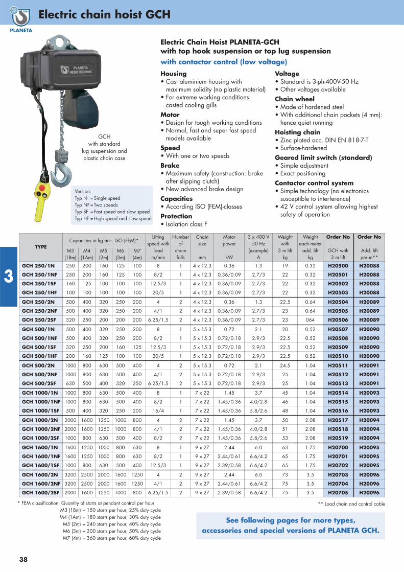
3
38
Electric chain hoist GCH
* FEM classification: Quantity of starts at pendant control per hourM3 (1Bm) = 150 starts per hour, 25% duty cycleM4 (1Am) = 180 starts per hour, 30% duty cycle
M5 (2m) = 240 starts per hour, 40% duty cycleM6 (3m) = 300 starts per hour, 50% duty cycleM7 (4m) = 360 starts per hour, 60% duty cycle
See following pages for more types, accessories and special versions of PLANETA GCH.
GCH with standard
lug suspension andplastic chain case
Version:Typ N =Single speedTyp NF=Two speedsTyp SF =Fast speed and slow speedTyp HF =High speed and slow speed
** Load chain and control cable
Electric Chain Hoist PLANETA-GCH with top hook suspension or top lug suspension with contactor control (low voltage)
Housing• Cast aluminium housing with
maximum solidity (no plastic material)• For extreme working conditions:
casted cooling gillsMotor• Design for tough working conditions• Normal, fast and super fast speed
models availableSpeed• With one or two speedsBrake • Maximum safety (construction: brake
after slipping clutch)• New advanced brake designCapacities• According ISO (FEM)-classesProtection• Isolation class F
Voltage• Standard is 3-ph-400V-50 Hz• Other voltages availableChain wheel• Made of hardened steel• With additional chain pockets (4 mm):
hence quiet runningHoisting chain• Zinc plated acc. DIN EN 818-7-T• Surface-hardenedGeared limit switch (standard)• Simple adjustment• Exact positioningContactor control system• Simple technology (no electronics
susceptible to interference)• 42 V control system allowing highest
safety of operation
TYPECapacities in kg acc. ISO (FEM)*
Liftingspeed with
loadm/min
Number of
chainfalls
Chainsize
mm
Motor power
kW
3 x 400 V50 Hz
(example)A
Weightwith
3 m liftkg
Weighteach meter
add. liftkg
Order No
GCH with3 m lift
Order No
Add. liftper m**
M3(1Bm)
M4(1Am)
M5(2m)
M6(3m)
M7(4m)
GCH 250/1N 250 200 160 125 100 8 1 4 x 12.3 0.36 1.3 19 0.32 H20500 H20088
GCH 250/1NF 250 200 160 125 100 8/2 1 4 x 12.3 0.36/0.09 2.7/3 22 0.32 H20501 H20088
GCH 250/1SF 160 125 100 100 100 12.5/3 1 4 x 12.3 0.36/0.09 2.7/3 22 0.32 H20502 H20088
GCH 250/1HF 100 100 100 100 100 20/5 1 4 x 12.3 0.36/0.09 2.7/3 22 0.32 H20503 H20088
GCH 250/2N 500 400 320 250 200 4 2 4 x 12.3 0.36 1.3 22.5 0.64 H20504 H20089
GCH 250/2NF 500 400 320 250 200 4/1 2 4 x 12.3 0.36/0.09 2.7/3 23 0.64 H20505 H20089
GCH 250/2SF 320 250 200 200 200 6.25/1.5 2 4 x 12.3 0.36/0.09 2.7/3 23 064 H20506 H20089
GCH 500/1N 500 400 320 250 200 8 1 5 x 15.3 0.72 2.1 20 0.52 H20507 H20090
GCH 500/1NF 500 400 320 250 200 8/2 1 5 x 15.3 0.72/0.18 2.9/3 22.5 0.52 H20508 H20090
GCH 500/1SF 320 250 200 160 125 12.5/3 1 5 x 15.3 0.72/0.18 2.9/3 22.5 0.52 H20509 H20090
GCH 500/1HF 200 160 125 100 100 20/5 1 5 x 12.3 0.72/0.18 2.9/3 22.5 0.52 H20510 H20090
GCH 500/2N 1000 800 630 500 400 4 2 5 x 15.3 0.72 2.1 24.5 1.04 H20511 H20091
GCH 500/2NF 1000 800 630 500 400 4/1 2 5 x 15.3 0.72/0.18 2.9/3 25 1.04 H20512 H20091
GCH 500/2SF 630 500 400 320 250 6.25/1.5 2 5 x 15.3 0.72/0.18 2.9/3 25 1.04 H20513 H20091
GCH 1000/1N 1000 800 630 500 400 8 1 7 x 22 1.45 3.7 45 1.04 H20514 H20093
GCH 1000/1NF 1000 800 630 500 400 8/2 1 7 x 22 1.45/0.36 4.0/2.8 46 1.04 H20515 H20093
GCH 1000/1SF 500 400 320 250 200 16/4 1 7 x 22 1.45/0.36 5.8/2.6 48 1.04 H20516 H20093
GCH 1000/2N 2000 1600 1250 1000 800 4 2 7 x 22 1.45 3.7 50 2.08 H20517 H20094
GCH 1000/2NF 2000 1600 1250 1000 800 4/1 2 7 x 22 1.45/0.36 4.0/2.8 51 2.08 H20518 H20094
GCH 1000/2SF 1000 800 630 500 400 8/2 2 7 x 22 1.45/0.36 5.8/2.6 53 2.08 H20519 H20094
GCH 1600/1N 1600 1250 1000 800 630 8 1 9 x 27 2.44 6.0 63 1.75 H20700 H20095
GCH 1600/1NF 1600 1250 1000 800 630 8/2 1 9 x 27 2.44/0.61 6.6/4.2 65 1.75 H20701 H20095
GCH 1600/1SF 1000 800 630 500 400 12.5/3 1 9 x 27 2.39/0.58 6.6/4.2 65 1.75 H20702 H20095
GCH 1600/2N 3200 2500 2000 1600 1250 4 2 9 x 27 2.44 6.0 73 3.5 H20703 H20096
GCH 1600/2NF 3200 2500 2000 1600 1250 4/1 2 9 x 27 2.44/0.61 6.6/4.2 75 3.5 H20704 H20096
GCH 1600/2SF 2000 1600 1250 1000 800 6.25/1.5 2 9 x 27 2.39/0.58 6.6/4.2 75 3.5 H20705 H20096

39
Electric chain hoist GCH
3
Hook mounting *
for GCH
Order No.
TYPE 250 / TYP 500 H20760
TYPE 1000 H20761
TYPE 1600 / TYP 2000 / TYP 2500 H20762
Options for GCH * Order No.
Motor thermal protection / Klixon 140°C H20073
Special motor voltage H20076
Special control voltage H20078
CEE-plug with 5m connection cable H20080
Counter of operation hours H20553
Radio remote control for hoist only H20557
Radio remote control for hoist and trolley H20558
Limit switches for electric motor trolley H20559
Rain cover of textile material H20561
Connecting lug GCH 250-2-L87-05 H20162
Connecting lug GCH 250-1-500-1-L87-05 H20163
Connecting lug GCH 500-2-L87-10 H20164
Connecting lug GCH 1000-1-L87-10 H20165
Connecting lug GCH 1000-2-L87-20 H20166
Connecting lug GCH 1600-1-2000-1-L87-20 H20167
Connecting lug GCH 2500-1-L87-30 H20168
Connecting lug GCH 1600-2-2000-2-2500-2-L87-50 H20169
Special options upon request:• Motor driven trolley
• Low headroom version• Synchronized hoists• Flexible one-hand-solution • Rust proof electric hoist• Hoists for theatres, stages and studios acc. BGV C1• Electric chain hoists for DUST Ex -areas
Ex II 3D Ex tc IIIA T130 °C Db• Electric hoists and trolleys for 1-Ph/230V (single phase)• Electric hoists for any other voltage
Chain case*for TYPE
Size of chain case
Version Order No.
GCH 250
up to 8 m Chain Plastic H20754
up to 16 m Chain Plastic H20755
up to 25 m Chain Textile H20756
GCH 500
up to 6 m Chain Plastic H20754
up to 12 m Chain Plastic H20755
up to 20 m Chain Textile H20756
GCH 1000up to 8 m Chain Plastic H20757
up to 35 m Chain Textile H20758
GCH 1600 up to 20 m Chain Textile H20758
GCH 2000 / 2500 up to 15 m Chain Textile H20758
* Only in connection with electric chain hoist/trolleyMore sizes for higher lifts upon request!
* Only in connection with electric chain hoist/trolley
* Only in connection with electric chain hoist/trolley
Rain cover of textile material
Electric motor trolley for GCH
Driving speed
m/min
Standardflange width
mm
Weight
kg
Order No.
EMF 50 * to 1000 kg 12/4 50 - 99 27 H20720
EMF 150 to 2000 kg 12/4 76 - 139 31 H20721
EMF 300 to 4000 kg 12/4 120 - 179 50 H20722
EMF 500 to 5000 kg 12/4 120 - 179 57 H20723
Wider flange width** – up to 300 – H20724
Manual push trolley forGCH
Standardflange width
mm
Weight
kg
Order No.
GHF 500 K to 500 kg 50 - 99 2.5 H20729
EHF 50 * to 1000 kg 50 - 99 7.5 H20730
EHF 150 to 2000 kg 76 - 139 13.5 H20731
EHF 300 to 4000 kg 120 - 179 27.5 H20732
EHF 500 to 5000 kg 120 - 179 27.5 H20733
Wider flange width** up to 300 – H20734
* Only in connection with GCH 500/2 ** Only in connection with trolley
* Only in connection with GCH 500/2 ** Only in connection with trolley
TYPECapacities in kg acc. ISO (FEM)*
Liftingspeed with
loadm/min
Number of
chainfalls
Chainsize
mm
Motorpower
kW
3 x 400 V50 Hz
(example)A
Weightwith
3 m liftkg
Weighteach meter
add. liftkg
Order No
GCH with3 m lift
Order No
Add. liftper m**
M3(1Bm)
M4(1Am)
M5(2m)
M6(3m)
M7(4m)
GCH 2000/1N 2000 1600 1250 1000 800 8 1 10 x 28 3.05 7.3 65 2.25 H20706 H20101
GCH 2000/1NF 2000 1600 1250 1000 800 8/2 1 10 x 28 3.05/0.77 8.0/4.5 67 2.25 H20707 H20101
GCH 2000/1SF 1250 1000 800 630 500 12.5/3 1 10 x 28 2.98/0.72 8.0/4.5 67 2.25 H20708 H20101
GCH 2000/2N 4000 3200 2500 2000 1600 4 2 10 x 28 3.05 7.3 76 4.5 H20709 H20102
GCH 2000/2NF 4000 3200 2500 2000 1600 4/1 2 10 x 28 3.05/0.77 8.0/4.5 78 4.5 H20710 H20102
GCH 2000/2SF 2500 2000 1600 1250 1000 6.25/1.5 2 10 x 28 2.98/0.72 8.0/4.5 78 4.5 H20711 H20102
GCH 2500/1N 2500 2000 1600 1250 1000 6.4 1 10 x 28 3.05 7.7 65 2.25 H20712 H20103
GCH 2500/1NF 2500 2000 1600 1250 1000 6.4/1.6 1 10 x 28 3.05/0.77 8.2/4.4 67 2.25 H20713 H20103
GCH 2500/1SF 1600 1250 1000 800 630 10/2.5 1 10 x 28 3.05/0.77 8.2/4.4 67 2.25 H20714 H20103
GCH 2500/2N 5000 4000 3200 2500 2000 3.2 2 10 x 28 3.05 7.7 76 4.5 H20715 H20104
GCH 2500/2NF 5000 4000 3200 2500 2000 3.2/0.8 2 10 x 28 3.05/0.77 8.2/4.4 78 4.5 H20716 H20104
GCH 2500/2SF 3200 2500 2000 1600 1250 5/1.25 2 10 x 28 3.05/0.77 8.2/4.4 78 4.5 H20717 H20104
** Load chain and control cable

3
40
Electric chain hoist GCH
Type GCHwith lug eye mounting
A
BNC
D
H K
M
Type GCH with electric motor trolley
E
J
F L G
TYPE GCH ... 250/1 250/2 500/1 500/2 1000/1 1000/2 1600/1 1600/2 2000/1 2000/2 2500/1 2500/2
A (Dimensions) mm
B mm
C mm
D mm
E mm
F mm
G mm
H mm
J mm
K mm
L mm
M mm
N mm
281
309
246
40
277
250
209
369
418
398
50-99
431
36
281
309
246
40
277
250
209
408
457
398
50-99
470
36
281
309
246
40
277
250
209
377
426
398
50-99
439
36
281
309
246
40
277
250
209
417
466
398
50-99
479
36
367
367
321
52
293
253
211
482
542
565
76-139
553
43
367
367
321
52
293
253
211
556
616
565
76-139
627
43
424
389
345
75
323
259
217
608
637
646
120-179
638
50
424
389
345
75
323
259
217
690
719
646
120-179
720
50
424
389
345
75
323
259
217
608
637
646
120-179
638
50
424
389
345
75
323
259
217
690
719
646
120-179
720
50
424
389
345
75
323
259
249
608
637
646
120-179
638
50
424
389
345
75
323
259
249
690
719
646
120-179
720
50
Electric chain hoist GCH with electric motor trolley EMF
Electric chainhoist GCH withhook mounting
Electric chain hoist GCHwith push trolley EHF
Double chain fall
Single chain fall

41
3
Electric chain hoist GCH

3
42
Electric chain hoist / accessories
Trolley buffer assembly
Trolley bufferThe ideal trolley limit stop, suitable for all types of manual trolley,reel chain trolley and electric trolley up to a maximum load bearingcapacity of 10 t! With just a few simple actions it is clamped to therequired end of the track on a parallel flange carrier section.In this way it fulfils various functions: Path limit to prevent crashes,holding hoists in the desired position, securing the trolley againstrolling away inadvertently, absorbing impact energy and moreprecise braking.
Trolley buffer
TYPEBeam widths mm
Order No.
Setconsisting of
2 pieces
K1 90 - 300 H20066
Please photocopy, fill in and FAX to us!
✂
Enquiry help for electric hoists1. What tasks will the hoist be used for?
...........................................................................................
...........................................................................................
2. Type of hoist: Electric chain hoist ❏ Electric cable hoist ❏
3. How often is the nominal load lifted?
................................. /day ................................. /hour
4. How often is the partial load lifted? ................................. /day
5. How many load cycles per day? ..........................................
6. Distance covered per hoisting cycle: ..................................... m
7. Speed:
a) Required main hoisting speed ..................... m/min
b) 1 speed ❏
c) 2 speeds ❏
8. Clear height for electric hoist (short model required?): .......... mm
9. Total weight of load to be hoisted including load-carrying equipment: ............ kg
10. Lifting height (standard: 3 m): ............ m
11. Mounting height/trolley track height (Floor to bottom edge of carrier) ............. m
12. Operating height (distance from floor or operating platform to bottom edge of carrier): ............. m
13. Control cable length: ............. m
Operating voltage V= ............ at ............ Hz
Control voltage V= ............
Direct control ❏ Contactor control ❏ Radio control ❏
14. Operational environment - distinctive features:
Dust ❏
Extreme temperatures (over ....... degrees, under ....... degrees) ❏
Explosion protection required ❏
Splash water ❏
Rainwater ❏
Air humidity ❏
Use outdoors ❏
Hook attachment ❏
Eye attachment ❏
15. Trolley ❏
Manual drive ❏
Reel drive ❏
Electric drive ❏
1 speed ❏
2 speeds ❏
16. Carrier size:
a) Flange width: ................................. mm
b) Trolley track length: ................................... m
c) Minimum curve radius: ................................... m
17. Power supply required ❏
18. Trolley track buffer for track boundary ❏
19. Set of information signs according to BGV ❏
20. Assembly by PLANETA specialist fitters required ❏
21. Crane removal by our experts required ❏
22. Quote for maintenance contract ❏

43
Electric chain hoist MONTI
3
Electric chain hoist MONTIThe new MONTI electric chain hoist is the ideal aid duringassembly. Thanks to its light and compact construction, the chain hoist is easy to install and transport in the case supplied. It is ready for operation with a controller, chain and connection cable.
Features:
• 230 V / 1ph / 50 Hz motor
• Soft start enables accurate placement
• 2 speeds: Main hoisting speed / precision hoistingspeed infinitely adjustable
• Protection class IP 54, insulation class F
• 24-volt control voltage with EMERGENCY STOP
• FEM classification: M4 (1Am)
• Control cable length: 2.5 m
• Connection cable with two-pin earthed plug: 1.5 m
• Overload protection by slipping clutch
• Limit switch for top and bottom hook end position
• Includes chain box for 3 m standard lifting height and transport case
Chain boxNo.
Chain box dimensions(mm) L x W x H
Order No.
# 1 90 x 130 x 185 H20790
# 2 120 x 160 x 230 H20791
# 3 120 x 160 x 260 H20792
# 4 130 x 170 x 310 H20793
TYPEMONTI ...
Dimensions (mm)
A B C D E F G H I J K
240 364 182 182 89 423 400 25 25 260 108 152
480 364 182 182 109 423 497 31 30 260 84 176
TYPE MONTI ... 240 480
Rated load kg 240 480
Motor output W 600
Duty rating % ED 30
Rated Current 230 V (5 A)
Lifting speed m/min. 0-3.4/12.8 0-1.6/6.3
Standard lifting height m 3
Number of chain falls 1 2
Load chain diameter mm 4 x 12
Net weight kg 16.5 19.4
Packing (L x W x H) mm 470 x 390 x 200
MONTI with 3 m lift Order No. H20780 H20781
Additional for more lift/m Order No. H20782 H20783
Additional for 3 mSet of control cable elongation
Order No. H20784 H20784
Additional for 6 mSet of control cable elongation
Order No. H20785 H20785
Additional for 9 mSet of control cable elongation
Order No. H20786 H20786
Specifications:
TYPEMONTI ...
Ratedload
Chain(mm)
Chain length (m)
up to 5 up to 10 up to 15 up to 20
240 240 kgØ 4 x 12 # 1 # 2 # 3 # 4
480 480 kg
Chain box selection
� MONTI is packed in a handy case forease of transport.
slowspeedregulation
Liftin
g he
ight
3 m

3
44
Electric rope hoists
This small winch is mostly used for house repair, changing of windows, lifting cement sacks into the upper floor - just a quick installed tool for many applications in which the worker wants to carry loads up to higher floors or levels. They are not allowed to be used for moving of persons. The BW-rope hoist comes ready for use.
Features:
• Lightweight and compact design• Allows easy installation• Automatic upper limit switch. When
rope disc touches the limit arm, hoisting is automatically stopped
• Mechanical braking system• Sensor arm automatically stops motor
if the wire rope is completely unwinded• Single phase domestic power supply• With 5 m power lead and industry
plug for your country• With 10 m pendant control• Wire rope with safety hook• 360° weight hook with safety latch• Motor rating IP44• Heavy duty IP65 waterproof switch with
emergency stop K613A as option available
Options:
• Swivel jib arm, 180°
• 10 m control cable extension
Electric rope hoist PLANETA-BW
BW-230
TYPE BW-80 BW-160 BW-230 BW-300
Capacity in all rope layers kgRope lifting speed* 1st rope layer m/minRope lifting speed * top layer m/minMotor data 230 V
Lifting height (rope length) mRope diameter mmA (Dimensions) mmB mmC mmD mmE mmF mmG mmWeight of complete hoist kg
801830
0.8 kW/4 A/25 % ED
234
20010416860526633927018
1601522
1.2 kW/6 A/25 % ED
305
24411518264028036028523
2309
141.3 kW/6.5 A/
25 % ED245
24411518264028036028524
3009
131.5 kW/7.5A/
25 % ED245
24411518264028036028525
Rope hoist Order No. H20619 H20621 H20620 H20622
Control cable extension including plugs
Order No. H20603 H20603 H20603 H20603
Safe
pill
ar
is c
ust
om
er’s
res
ponsi
bili
ty
TYPEMax.
capacitykg
Max. length of jib
mm
OrderNo.
SA-250 250 1100 H20607
SA-600 600 750 H20608
Swivel jib armAttach the swivel arm with two clamps (Ø 40-55 mm) at a vertical strong andsafely fixed pipe! Hang hoist in – READY!
The device is equipped with a safety hookas standard.
Swivel jib arm with 180° rotation.
* Rope lifting speed at full load

45
4

Winch inquiry checklist
46
4
Winch Inquiry Checklist Please see backside of catalogue for FAX-Number!
7. Location of control
� Direct control on ...... m control cable
� Low voltage control box
� Panel mounted on winch frame
� for mounting on walls, with ...... m distance to winch
� Frequency inverter
� mounted on winch frame
� for mounting on walls, with ...... m distance to winch
8. Operation
� Push buttons in the control panel door
� Pendant control with ...... m control cable
� Radio Remote control
� Wall-mounted push-button
� Food pedal
� Several with selector switch in the control panel door
9. Options for control
� Panel mounting appliance inlet
� Power supply cable with ...... m cable
� Power shut-off switch
� Electric overload protection
� Full motor protection (Temperature monitoring)
10. Other requirements
....................................................................................................
....................................................................................................
....................................................................................................
....................................................................................................
....................................................................................................
11. Please sketch your application here
* Please note the required fi elds!
1. Kind of drive and quantity *
� manually
� electric, Operating voltage ...... Phases /...... V AC /...... Hz
� pneumatic, Flow volume ...... l / sec / ...... bar
� hydraulic, Flow volume ...... l / min / ...... bar
Quantity: ...... pieces
2. Site of Operation and capacity *
� Pulling winch with ...... daN pulling force and ...... rope length
� Lifting winch with ...... kg lifting capacity and ...... m rope length
� Traversing winch with ...... daN pulling force and ...... m rope length
� Capstan winch with ...... daN pulling force
� Traction winch with ...... daN pulling force
If the pulling or lifting capacity is not known, please describe your application with the length of the path, weight of load and rolling conditions for your pulling applications. For lifting applications please also describe the angle or slope of the path.
....................................................................................................
....................................................................................................
....................................................................................................
....................................................................................................
....................................................................................................
3. Rope speed
� slow (1-5 m/min) � medium (5-15 m/min)
� fast (> 15 m/min) � exactly ...... m / min
� adjustable from ...... m / min up to ...... m / min
� 2-speed ...... m / min and ...... m / min
4. Site of Operation
Distance to the fi rst reeving ...... m
� inside � outside � outside with seawater
5. Load type
� Goods � Pending goods above people
� Goods to be moved above people � People
6. Winch options
� Rope ...... m � Rope supplied loose � Rope spooled on winch
� Rope-end, plain � Rope-end with thimble � Load hook
� Grooved drum � Pressure roller � Spindle limit switch
� Slack wire switch � Disengaging clutch � Spooling gear
� Drum guard � Brake acting on drum
� mechanic � automatic
� Emergency crank � Manual brake release
� Two rope exits with ...... m distance
� More rope exits like shown on sketch
� Explosion-proof protection class ......
Company name: ...............................................................................
Personal name: .................................................................................
Phone: ................................................................................................
Fax: ....................................................................................................
Company stamp:
Please photocopy and Send a FAX!

47
Rope winch types
Mode of application and loadbearing capacityPulling winches are designed to pull loads on a 100 % flat surface. The pulling force is calculated from the mass of the load tobe pulled multiplied by the load's rolling resistance. The rolling resistances for the typical applications are around 0.150 for rubberwheels on concrete surfaces and around 0.005 for steel wheelsmounted on an anti-friction bearing that are on tracks. If the load ishoisted on an angled surface, the cable winch must be designed asa hoist winch.
Hoist winches must be used if a load is to be raised and held bythe cable winch. This applies to hoisting vertically and also to pullingthe load along an angled track. Cable winches for hoisting areequipped with spring-loaded brakes on the motor as standard and therefore guarantee that the load will be held securely. In addition, cablewinches for hoisting are equipped with higher safety factors than cablewinches that are used purely for pulling for example.
A traversing winch can be used to move a load in two directionson a level. You can therefore move a carriage forwards and back-wards for example. The cable drum is designed for two cables, isscored and winds in only one layer.
Capstan winches are endless winches that do not store the cableon a cable drum but allow the cable to run through "endlessly". A counterforce such as the operator's manual force is multiplied bywinding the cable around the capstan head several times. In this way,a much larger pulling force can be achieved from manual force.For example, they stand on deck on a ship and are used to pull cablesand ropes in many different directions.
Traction winches are endless winches like the capstan winches.They work on the same principle of increasing force due to windingfriction. The cable is better fed and protected thanks to their designwith two traction sheaves and multiple scores.
Traction winches are normally located on carriages that travel forwards and backwards. The pulling cable is stretched between the two ends of the guide rail.
Information for safe operation: To ensure that the cable is wound onto the cable drum in an orderly manner,
the cable's permitted angle of deflectionmust not be exceeded. For this reason, the cable is normally guidedfrom the cable drum over a fixed deflection roller at first. This is alignedin the centre of the drum at a specified distance from the cable drum.This prevents the angle of deflection being exceeded. This distancemainly depends on the drum length and the relationship between the drum diameter and the cable diameter, and is specified in each quotation.
Pulling winch
Hoist winch
Traversing winch
Capstan winch
Traction winch
Distance to first deflection
Cable deflection angle
4
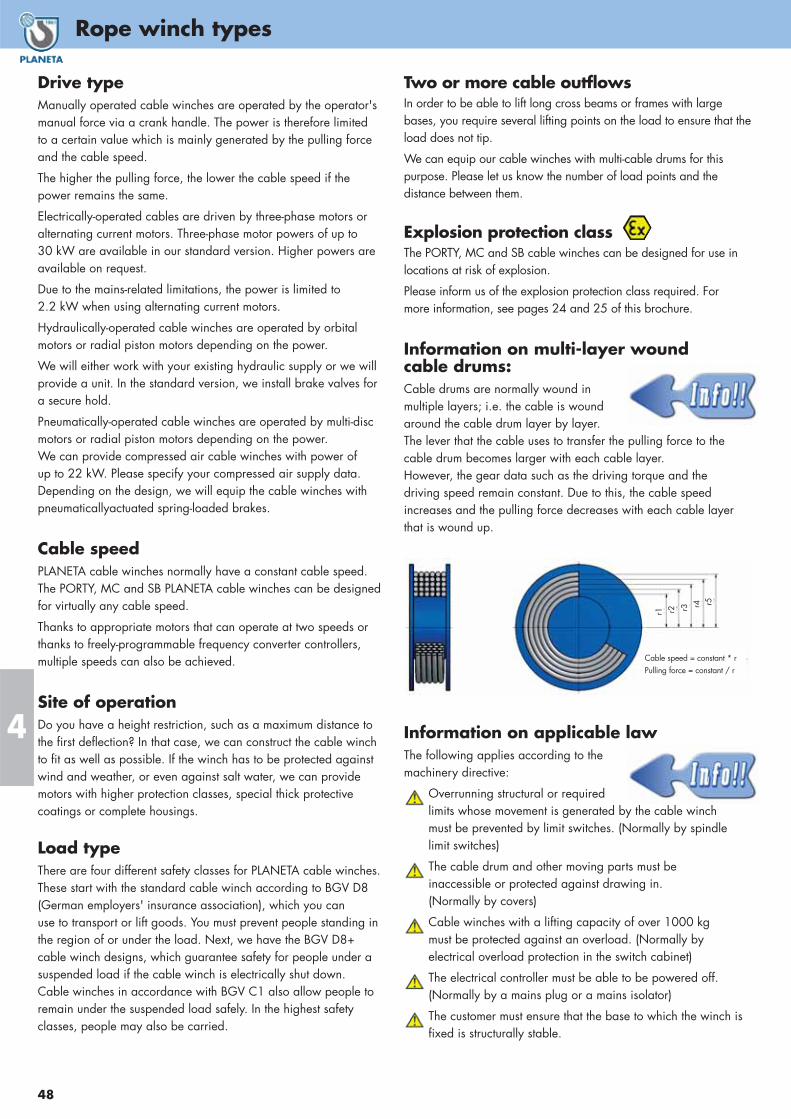
Rope winch types
48
4
Drive typeManually operated cable winches are operated by the operator'smanual force via a crank handle. The power is therefore limited to a certain value which is mainly generated by the pulling forceand the cable speed.
The higher the pulling force, the lower the cable speed if thepower remains the same.
Electrically-operated cables are driven by three-phase motors oralternating current motors. Three-phase motor powers of up to 30 kW are available in our standard version. Higher powers areavailable on request.
Due to the mains-related limitations, the power is limited to 2.2 kW when using alternating current motors.
Hydraulically-operated cable winches are operated by orbitalmotors or radial piston motors depending on the power.
We will either work with your existing hydraulic supply or we willprovide a unit. In the standard version, we install brake valves fora secure hold.
Pneumatically-operated cable winches are operated by multi-discmotors or radial piston motors depending on the power. We can provide compressed air cable winches with power of up to 22 kW. Please specify your compressed air supply data.Depending on the design, we will equip the cable winches withpneumaticallyactuated spring-loaded brakes.
Cable speedPLANETA cable winches normally have a constant cable speed.The PORTY, MC and SB PLANETA cable winches can be designedfor virtually any cable speed.
Thanks to appropriate motors that can operate at two speeds orthanks to freely-programmable frequency converter controllers, multiple speeds can also be achieved.
Site of operationDo you have a height restriction, such as a maximum distance tothe first deflection? In that case, we can construct the cable winchto fit as well as possible. If the winch has to be protected againstwind and weather, or even against salt water, we can providemotors with higher protection classes, special thick protectivecoatings or complete housings.
Load type There are four different safety classes for PLANETA cable winches.These start with the standard cable winch according to BGV D8(German employers' insurance association), which you canuse to transport or lift goods. You must prevent people standing inthe region of or under the load. Next, we have the BGV D8+cable winch designs, which guarantee safety for people under asuspended load if the cable winch is electrically shut down. Cable winches in accordance with BGV C1 also allow people toremain under the suspended load safely. In the highest safety classes, people may also be carried.
Two or more cable outflowsIn order to be able to lift long cross beams or frames with largebases, you require several lifting points on the load to ensure that theload does not tip.
We can equip our cable winches with multi-cable drums for thispurpose. Please let us know the number of load points and thedistance between them.
Explosion protection classThe PORTY, MC and SB cable winches can be designed for use inlocations at risk of explosion.
Please inform us of the explosion protection class required. Formore information, see pages 24 and 25 of this brochure.
Information on multi-layer wound cable drums: Cable drums are normally wound inmultiple layers; i.e. the cable is woundaround the cable drum layer by layer.The lever that the cable uses to transfer the pulling force to thecable drum becomes larger with each cable layer.However, the gear data such as the driving torque and thedriving speed remain constant. Due to this, the cable speedincreases and the pulling force decreases with each cable layerthat is wound up.
Information on applicable law The following applies according to themachinery directive:
Overrunning structural or required limits whose movement is generated by the cable winch must be prevented by limit switches. (Normally by spindle limit switches)
The cable drum and other moving parts must beinaccessible or protected against drawing in.(Normally by covers)
Cable winches with a lifting capacity of over 1000 kgmust be protected against an overload. (Normally byelectrical overload protection in the switch cabinet)
The electrical controller must be able to be powered off.(Normally by a mains plug or a mains isolator)
The customer must ensure that the base to which the winch isfixed is structurally stable.
r1 r2 r3 r4 r5
Cable speed = constant * rPulling force = constant / r
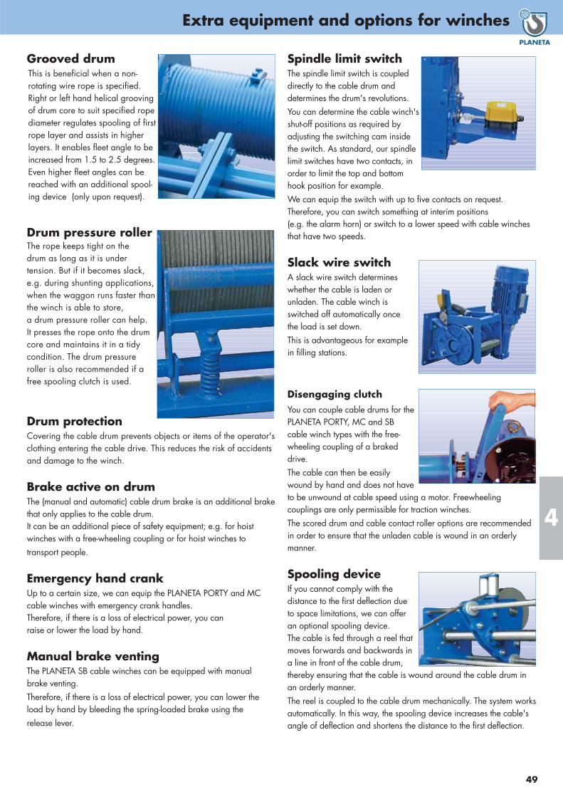
49
Extra equipment and options for winches
4
Grooved drumThis is beneficial when a non-rotating wire rope is specified.Right or left hand helical groovingof drum core to suit specified ropediameter regulates spooling of firstrope layer and assists in higherlayers. It enables fleet angle to beincreased from 1.5 to 2.5 degrees.Even higher fleet angles can bereached with an additional spool-ing device (only upon request).
Drum pressure roller The rope keeps tight on the drum as long as it is under tension. But if it becomes slack,e.g. during shunting applications,when the waggon runs faster thanthe winch is able to store, a drum pressure roller can help. It presses the rope onto the drumcore and maintains it in a tidycondition. The drum pressureroller is also recommended if afree spooling clutch is used.
Drum protectionCovering the cable drum prevents objects or items of the operator'sclothing entering the cable drive. This reduces the risk of accidentsand damage to the winch.
Brake active on drumThe (manual and automatic) cable drum brake is an additional brakethat only applies to the cable drum.It can be an additional piece of safety equipment; e.g. for hoist winches with a free-wheeling coupling or for hoist winches totransport people.
Emergency hand crank Up to a certain size, we can equip the PLANETA PORTY and MCcable winches with emergency crank handles.Therefore, if there is a loss of electrical power, you canraise or lower the load by hand.
Manual brake ventingThe PLANETA SB cable winches can be equipped with manualbrake venting.Therefore, if there is a loss of electrical power, you can lower theload by hand by bleeding the spring-loaded brake using therelease lever.
Spindle limit switchThe spindle limit switch is coupleddirectly to the cable drum and determines the drum's revolutions.You can determine the cable winch'sshut-off positions as required byadjusting the switching cam insidethe switch. As standard, our spindlelimit switches have two contacts, inorder to limit the top and bottomhook position for example.We can equip the switch with up to five contacts on request. Therefore, you can switch something at interim positions (e.g. the alarm horn) or switch to a lower speed with cable winchesthat have two speeds.
Slack wire switchA slack wire switch determineswhether the cable is laden orunladen. The cable winch is switched off automatically oncethe load is set down.This is advantageous for example in filling stations.
Disengaging clutchYou can couple cable drums for thePLANETA PORTY, MC and SBcable winch types with the free-wheeling coupling of a brakeddrive.The cable can then be easily wound by hand and does not haveto be unwound at cable speed using a motor. Freewheeling couplings are only permissible for traction winches.The scored drum and cable contact roller options are recommendedin order to ensure that the unladen cable is wound in an orderly manner.
Spooling deviceIf you cannot comply with thedistance to the first deflection due to space limitations, we can offeran optional spooling device. The cable is fed through a reel thatmoves forwards and backwards ina line in front of the cable drum,thereby ensuring that the cable is wound around the cable drum inan orderly manner.The reel is coupled to the cable drum mechanically. The system worksautomatically. In this way, the spooling device increases the cable'sangle of deflection and shortens the distance to the first deflection.
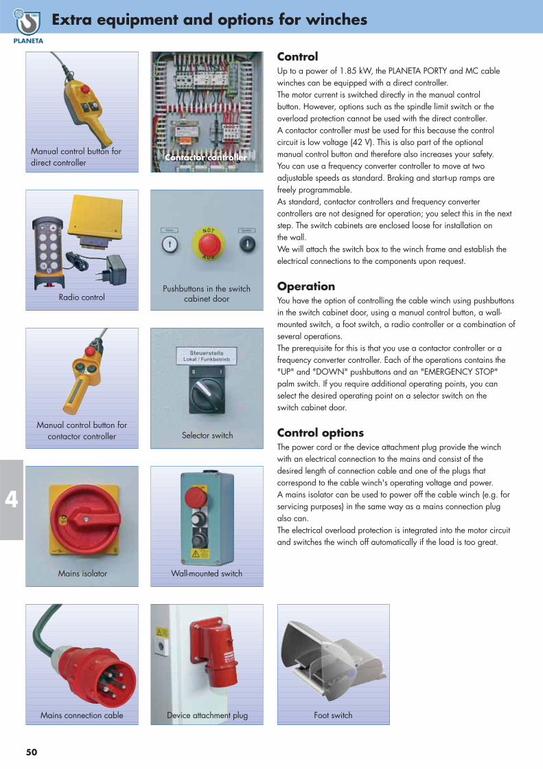
Extra equipment and options for winches
50
4
ControlUp to a power of 1.85 kW, the PLANETA PORTY and MC cablewinches can be equipped with a direct controller.The motor current is switched directly in the manual controlbutton. However, options such as the spindle limit switch or theoverload protection cannot be used with the direct controller.A contactor controller must be used for this because the controlcircuit is low voltage (42 V). This is also part of the optionalmanual control button and therefore also increases your safety.You can use a frequency converter controller to move at twoadjustable speeds as standard. Braking and start-up ramps arefreely programmable.As standard, contactor controllers and frequency convertercontrollers are not designed for operation; you select this in the nextstep. The switch cabinets are enclosed loose for installation on the wall.We will attach the switch box to the winch frame and establish theelectrical connections to the components upon request.
OperationYou have the option of controlling the cable winch using pushbuttonsin the switch cabinet door, using a manual control button, a wall-mounted switch, a foot switch, a radio controller or a combination ofseveral operations.The prerequisite for this is that you use a contactor controller or afrequency converter controller. Each of the operations contains the"UP" and "DOWN" pushbuttons and an "EMERGENCY STOP"palm switch. If you require additional operating points, you canselect the desired operating point on a selector switch on theswitch cabinet door.
Control optionsThe power cord or the device attachment plug provide the winchwith an electrical connection to the mains and consist of thedesired length of connection cable and one of the plugs thatcorrespond to the cable winch's operating voltage and power.A mains isolator can be used to power off the cable winch (e.g. forservicing purposes) in the same way as a mains connection plugalso can.The electrical overload protection is integrated into the motor circuitand switches the winch off automatically if the load is too great.
Selector switch
Device attachment plug
Mains isolator
Pushbuttons in the switchcabinet doorRadio control
Manual control button forcontactor controller
Mains connection cable
Wall-mounted switch
Foot switch
SchützsteuerungContactor controllerManual control button fordirect controller
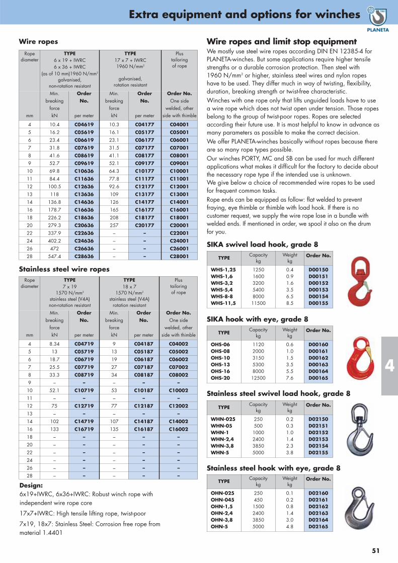
51
Extra equipment and options for winches
4
Wire ropes and limit stop equipmentWe mostly use steel wire ropes according DIN EN 12385-4 for PLANETA-winches. But some applications require higher tensilestrengths or a durable corrosion protection. Then steel with 1960 N/mm2 or higher, stainless steel wires and nylon ropeshave to be used. They differ much in way of twisting, flexibility,duration, breaking strength or twist-free characteristic.Winches with one rope only that lifts unguided loads have to use a wire rope which does not twist open under tension. Those ropesbelong to the group of twist-poor ropes. Ropes are selected according their future use. It is most helpful to know in advance asmany parameters as possible to make the correct decision.We offer PLANETA-winches basically without ropes because thereare so many rope types possible.Our winches PORTY, MC and SB can be used for much differentapplications what makes it difficult for the factory to decide about the necessary rope type if the intended use is unknown. We give below a choice of recommended wire ropes to be usedfor frequent common tasks.Rope ends can be equipped as follow: flat welded to prevent fraying, eye thimble or thimble with load hook. If there is no customer request, we supply the wire rope lose in a bundle withwelded ends. If mentioned in order, we spool it also on the drumfor you.
Wire ropes
Stainless steel wire ropes
Design:6x19+IWRC, 6x36+IWRC: Robust winch rope with independent wire rope core
17x7+IWRC: High tensile lifting rope, twist-poor
7x19, 18x7: Stainless Steel: Corrosion free rope from material 1.4401
TYPECapacity
kgWeight
kgOrder No.
OHS-06OHS-08OHS-10OHS-13OHS-16OHS-20
11202000315053008000
12500
0.61.01.53.55.57.6
D00160D00161D00162D00163D00164D00165
SIKA hook with eye, grade 8
TYPECapacity
kgWeight
kgOrder No.
OHN-025OHN-045OHN-1,5OHN-2,4OHN-3,8OHN-5
250450
1500240038505000
0.10.20.81.43.04.8
D02160D02161D02162D02163D02164D02165
TYPECapacity
kgWeight
kgOrder No.
WHN-025WHN-05WHN-1WHN-2,4WHN-3,8WHN-5
250500
1000240038505000
0.20.31.01.42.33.8
D02150D02151D02152D02153D02154D02155
Stainless steel hook with eye, grade 8
Stainless steel swivel load hook, grade 8
TYPECapacity
kgWeight
kgOrder No.
WHS-1,25WHS-1,6WHS-3,2WHS-5,4WHS-8-8WHS-11,5
12501600320054008000
11500
0.40.91.63.56.58.5
D00150D00151D00152D00153D00154D00155
SIKA swivel load hook, grade 8
Ropediameter
TYPE 6 x 19 + IWRC6 x 36 + IWRC
(as of 10 mm)1960 N/mm2
galvanised, non-rotation resistant
TYPE 17 x 7 + IWRC1960 N/mm2
galvanised,rotation resistant
Plus tailoringof rope
mm
Min.breaking
forcekN
OrderNo.
per meter
Min.breaking
forcekN
OrderNo.
per meter
Order No.One side
welded, otherside with thimble
4 10.4 C04619 10.3 C04177 C04001
5 16.2 C05619 16.1 C05177 C05001
6 23.4 C06619 23.1 C06177 C06001
7 31.8 C07619 31.5 C07177 C07001
8 41.6 C08619 41.1 C08177 C08001
9 52.7 C09619 52.1 C09177 C09001
10 69.8 C10636 64.3 C10177 C10001
11 84.4 C11636 77.8 C11177 C11001
12 100.5 C12636 92.6 C12177 C12001
13 118 C13636 109 C13177 C13001
14 136.8 C14636 126 C14177 C14001
16 178.7 C16636 165 C16177 C16001
18 226.2 C18636 208 C18177 C18001
20 279.3 C20636 257 C20177 C20001
22 337.9 C22636 – – C22001
24 402.2 C24636 – – C24001
26 472 C26636 – – C26001
28 547.4 C28636 – – C28001
Ropediameter
TYPE7 x 19
1570 N/mm2
stainless steel (V4A)non-rotation resistant
TYPE18 x 7
1570 N/mm2
stainless steel (V4A)rotation resistant
Plus tailoringof rope
mm
Min.breaking
forcekN
OrderNo.
per meter
Min.breaking
forcekN
OrderNo.
per meter
Order No.One side
welded, otherside with thimble
4 8.34 C04719 9 C04187 C04002
5 13 C05719 13 C05187 C05002
6 18.7 C06719 19 C06187 C06002
7 25.5 C07719 27 C07187 C07002
8 33.3 C08719 34 C08187 C08002
9 – – – – –
10 52.1 C10719 53 C10187 C10002
11 – – – – –
12 75 C12719 77 C12187 C12002
13 – – – – –
14 102 C14719 107 C14187 C14002
16 133 C16719 135 C16187 C16002
18 – – – – –
20 – – – – –
22 – – – – –
24 – – – – –
26 – – – – –
28 – – – – –
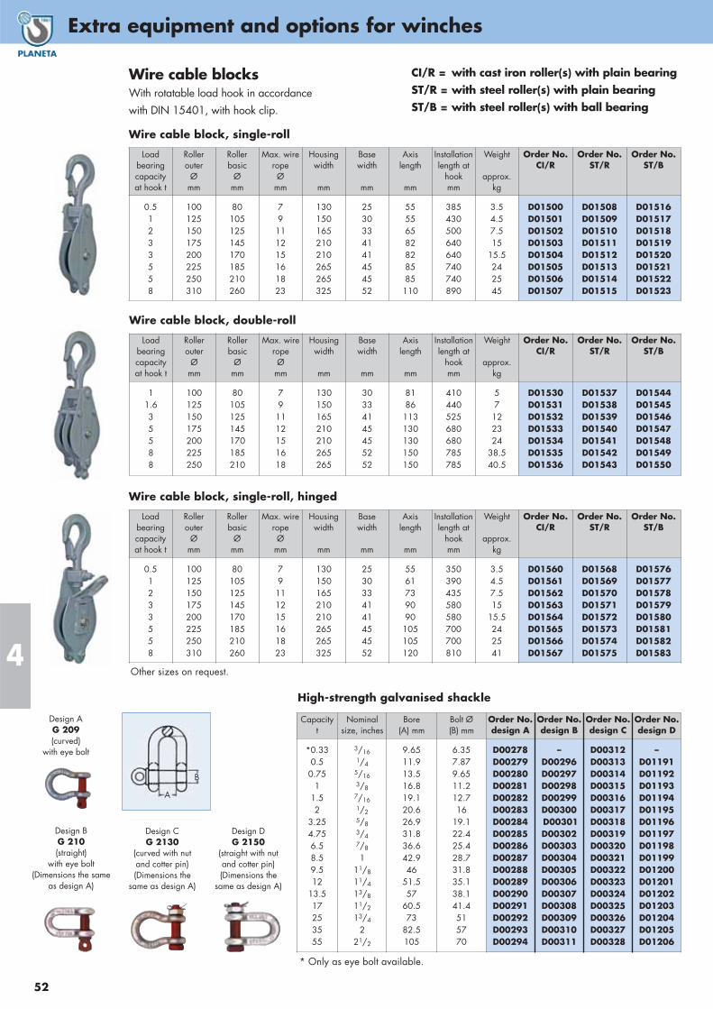
Extra equipment and options for winches
52
4
Wire cable blocksWith rotatable load hook in accordancewith DIN 15401, with hook clip.
CI/R = with cast iron roller(s) with plain bearingST/R = with steel roller(s) with plain bearingST/B = with steel roller(s) with ball bearing
Wire cable block, single-roll
Loadbearingcapacity at hook t
Roller outer
Ømm
Rollerbasic
Ømm
Max. wireropeØ
mm
Housingwidth
mm
Base width
mm
Axislength
mm
Installationlength at
hookmm
Weight
approx.kg
Order No.CI/R
Order No.ST/R
Order No.ST/B
0.51233558
100125150175200225250310
80105125145170185210260
79
111215161823
130150165210210265265325
2530334141454552
55556582828585
110
385430500640640740740890
3.54.57.515
15.5242545
D01500D01501D01502D01503D01504D01505D01506D01507
D01508D01509D01510D01511D01512D01513D01514D01515
D01516D01517D01518D01519D01520D01521D01522D01523
Wire cable block, double-roll
Loadbearingcapacityat hook t
Roller outer
Ømm
Rollerbasic
Ømm
Max. wireropeØ
mm
Housingwidth
mm
Base width
mm
Axislength
mm
Installationlength at
hookmm
Weight
approx.kg
Order No.CI/R
Order No.ST/R
Order No.ST/B
11.635588
100125150175200225250
80105125145170185210
79
1112151618
130150165210210265265
30334145455252
8186
113130130150150
410440525680680785785
57
122324
38.540.5
D01530D01531D01532D01533D01534D01535D01536
D01537D01538D01539D01540D01541D01542D01543
D01544D01545D01546D01547D01548D01549D01550
Wire cable block, single-roll, hinged
Loadbearingcapacityat hook t
Roller outer
Ømm
Rollerbasic
Ømm
Max. wireropeØ
mm
Housingwidth
mm
Base width
mm
Axislength
mm
Installationlength at
hookmm
Weight
approx.kg
Order No.CI/R
Order No.ST/R
Order No.ST/B
0.51233558
100125150175200225250310
80105125145170185210260
79
111215161823
130150165210210265265325
2530334141454552
5561739090
105105120
350390435580580700700810
3.54.57.515
15.5242541
D01560D01561D01562D01563D01564D01565D01566D01567
D01568D01569D01570D01571D01572D01573D01574D01575
D01576D01577D01578D01579D01580D01581D01582D01583
* Only as eye bolt available.
Other sizes on request.
High-strength galvanised shackle
Capacityt
Nominalsize, inches
Bore(A) mm
Bolt Ø(B) mm
Order No.design A
Order No.design B
Order No.design C
Order No.design D
*0.330.5
0.751
1.52
3.254.756.58.59.512
13.517253555
3/161/4
5/163/8
7/161/25/83/47/8
111/8
11/4
13/8
11/2
13/4
221/2
9.6511.913.516.819.120.626.931.836.642.946
51.557
60.573
82.5105
6.357.879.6511.212.716
19.122.425.428.731.835.138.141.4515770
D00278D00279D00280D00281D00282D00283D00284D00285D00286D00287D00288D00289D00290D00291D00292D00293D00294
–D00296D00297D00298D00299D00300D00301D00302D00303D00304D00305D00306D00307D00308D00309D00310D00311
D00312D00313D00314D00315D00316D00317D00318D00319D00320D00321D00322D00323D00324D00325D00326D00327D00328
–D01191D01192D01193D01194D01195D01196D01197D01198D01199D01200D01201D01202D01203D01204D01205D01206
Design AG 209(curved)
with eye bolt
Design BG 210(straight)
with eye bolt(Dimensions the same
as design A)
Design CG 2130
(curved with nutand cotter pin)(Dimensions the
same as design A)
Design DG 2150
(straight with nutand cotter pin)(Dimensions the
same as design A)
A
B

53
Electric rope winches
4
TYPE PLA-180B-V6
Max. capacity kg
Standard lift m
Lifting speed m/min
Rope diameter (compressed) mm
Class S3 duty cycle ED
Weight with standard lift kg
180
95
18
4.5
25 %
55
PLA-180B-V6 with 95 m lift Order No. H30173
PLA-180B-V6 without rope Order No. H30174
Electric winch PLA-180B-V6for wind energy towersThis winch is conceived for very large lifting heights in wind energytowers to lift up a tool case or small spare parts into the nacelle. The service man does not have to carry this load up the ladder or risksan overload of the elevator. PLA-180B-V6 is bottom-up attached to the ceiling (see drawing) and is running very fast.
Special features:• Single phase motor works 1-Ph/230V/50 Hz/1.5 kW • With short control cable • With rubber buffer covering the load hook to
protect tower walls outside• All screws, nuts, bars etc. made of stainless steel• Galvanized ground plate for strong base fixing• External HENSEL power connection box• Gear box with cooler fan• Limit switch for highest hook position
A lot of other solutionsfor the wind industryare available.
PLA -B200TYPE PLA-B200 PLA-B300
Max. capacity in all rope layers kgRope speed with full load m/minTensionMotor data
Possible lifting height/Pulling length mRope diameter x length mm x mWire rope constructionA (Dimensions) mmB mmC mmD mmE mmF mmG mmH mmWeight complete with wire rope kg
20011 - 16
1-Ph / 230 V / 50 Hz1.5 kW, 25% ED-S3,
FEM 1 Am, 12 A70
5 x 716 x 19, 1770 N/mm2
94135 *210197
205 *47027014732
30016 - 25
1-Ph / 230 V / 50 Hz2.3 kW, 25% ED-S3,
FEM 1 Am, 11 A29
6 x 30 6 x 19, 1770 N/mm2
94135 *210141
151 *50127014745
PLA-B Winch complete Order No. H30170 H30171
CE-package for PLA-B ... Order No. H30176 H30177
Ready for use
with rope and
pendantcontrol
Compact electric rope winch PLA-BPLA-B is concipated as a pulling winch, but can also lift and hold loads with an integrated brake. Since there are no limit switches, both rope end positions must be watched and supervised. The winch is a lightweight with its aluminium housing and easy to carry.
Features:• For 1-Ph/230 Volt/50 Hz – other voltages also for other countries• Includes 10 m pendant control cable• Includes 3 m power supply cable and country version plug• Motor protection IP 44• Control IP 65, splash water protected, with emergency stop button.
* = Please use as preferred option.
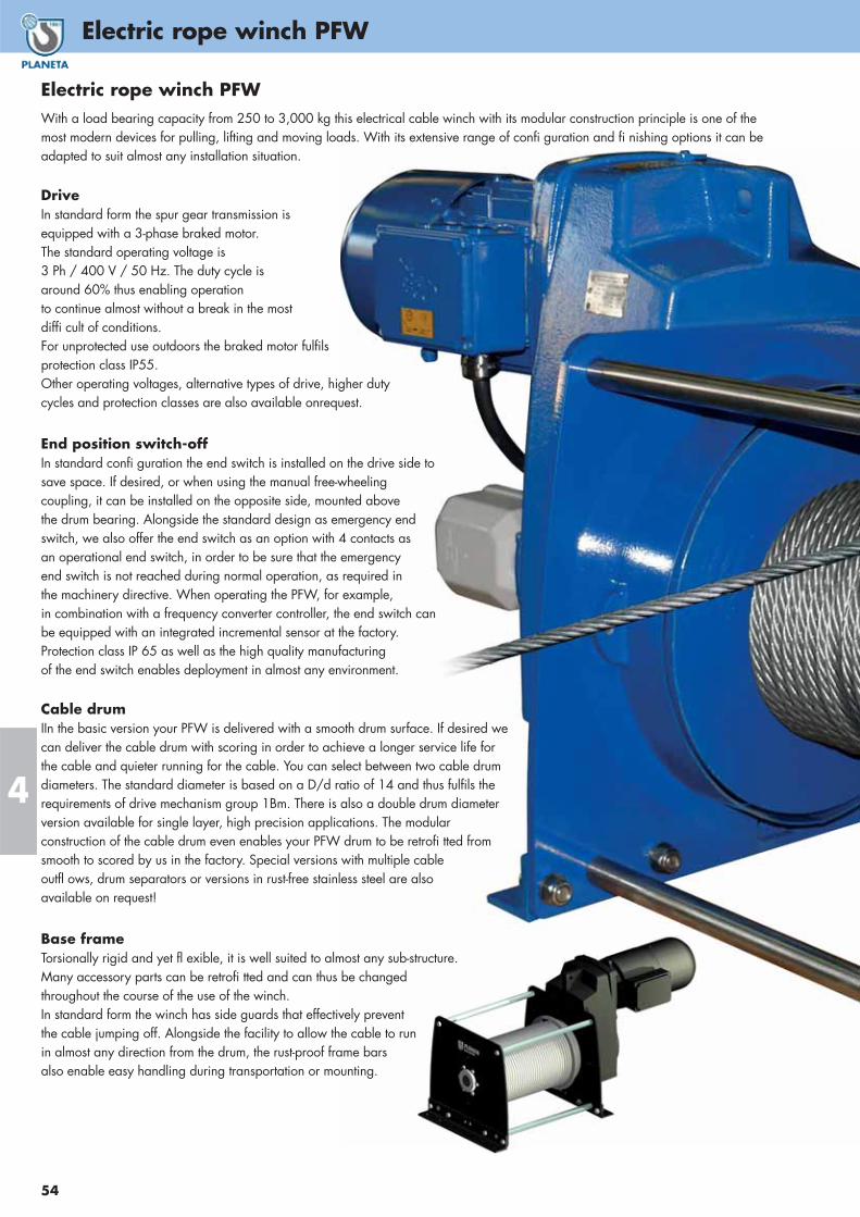
Electric rope winch PFW
54
Electric rope winch PFWWith a load bearing capacity from 250 to 3,000 kg this electrical cable winch with its modular construction principle is one of themost modern devices for pulling, lifting and moving loads. With its extensive range of confi guration and fi nishing options it can beadapted to suit almost any installation situation.
DriveIn standard form the spur gear transmission isequipped with a 3-phase braked motor.The standard operating voltage is3 Ph / 400 V / 50 Hz. The duty cycle isaround 60% thus enabling operationto continue almost without a break in the mostdiffi cult of conditions.For unprotected use outdoors the braked motor fulfilsprotection class IP55.Other operating voltages, alternative types of drive, higher dutycycles and protection classes are also available onrequest.
End position switch-offIn standard confi guration the end switch is installed on the drive side tosave space. If desired, or when using the manual free-wheelingcoupling, it can be installed on the opposite side, mounted abovethe drum bearing. Alongside the standard design as emergency endswitch, we also offer the end switch as an option with 4 contacts asan operational end switch, in order to be sure that the emergencyend switch is not reached during normal operation, as required in the machinery directive. When operating the PFW, for example, in combination with a frequency converter controller, the end switch can be equipped with an integrated incremental sensor at the factory.Protection class IP 65 as well as the high quality manufacturingof the end switch enables deployment in almost any environment.
Cable drumIIn the basic version your PFW is delivered with a smooth drum surface. If desired wecan deliver the cable drum with scoring in order to achieve a longer service life forthe cable and quieter running for the cable. You can select between two cable drumdiameters. The standard diameter is based on a D/d ratio of 14 and thus fulfils therequirements of drive mechanism group 1Bm. There is also a double drum diameterversion available for single layer, high precision applications. The modularconstruction of the cable drum even enables your PFW drum to be retrofi tted fromsmooth to scored by us in the factory. Special versions with multiple cableoutfl ows, drum separators or versions in rust-free stainless steel are alsoavailable on request!
Base frameTorsionally rigid and yet fl exible, it is well suited to almost any sub-structure.Many accessory parts can be retrofi tted and can thus be changedthroughout the course of the use of the winch.In standard form the winch has side guards that effectively preventthe cable jumping off. Alongside the facility to allow the cable to runin almost any direction from the drum, the rust-proof frame barsalso enable easy handling during transportation or mounting.
4

55
Electric rope winch PFW
4
OptionsThanks to the modular construction, for the fi rst time it is possible to retrofi t or change many options.
Foremost of these is the manual free-wheeling coupling, which de-couples the cable drum from the drive and thebrake for a rapid reeling off of the cable.
Simply select scored or extended drums, end switches, cable contact rollers, slack cable switches,protective drum covers, two or more cable outfl ows, manual brake venting, with or without
emergency hand crank and various protective paint systems from our options catalogue. Thus withour C5 painting per ISO 12944, in combination with a higher protection class for the motor andconnecting elementsmade from rustproof stainless steel, the offshore variant of the PFW can also
be used in salty sea-air environments or on ships. Other custom solutions are also possible onrequest. In standard confi guration the end switch is installed on the drive side. If desired, or whenusing the manual freewheeling coupling, it can be installed on the opposite side, mounted above
the drum bearing.
VersionsThe cable winch can also be appropriately
equipped to allow use in explosive atmospheres orfor use in theatres, stages and studios where persons
can be underneath the load whilst the hoist isoperating. Special versions such as two or multiple
cable applications and transverse winches arelikewise available from the standard range.
Made in GermanyThe PFW range combines a modern
design, innovative technology and superlativecomponents, which are produced exclusively in
Germany. Prior to shipping, each winch is testeddynamically with 125% of the nominal load and
leaves our factory with a 24 month guarantee.
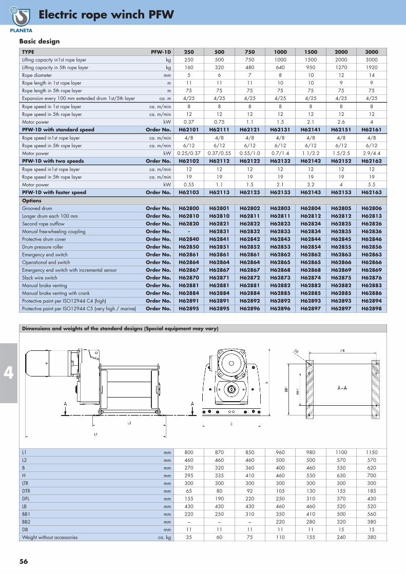
Electric rope winch PFW
56
4
Dimensions and weights of the standard designs (Special equipment may vary)
L1 mm 800 870 850 960 980 1100 1150L2 mm 460 460 460 500 500 570 570B mm 270 320 360 400 460 550 620H mm 295 335 410 460 550 630 700LTR mm 300 300 300 300 300 300 300DTR mm 65 80 92 105 130 155 185DFL mm 155 190 220 250 310 370 430LB mm 430 430 430 460 460 520 520BB1 mm 220 250 310 350 410 500 560BB2 mm – – – 220 280 320 380DB mm 11 11 11 11 11 15 15Weight without accessories ca. kg 35 60 75 110 155 240 380
TYPE PFW-1D 250 500 750 1000 1500 2000 3000Lifting capacity in1st rope layer kg 250 500 750 1000 1500 2000 3000Lifting capacity in 5th rope layer kg 160 320 480 640 950 1270 1920Rope diameter mm 5 6 7 8 10 12 14Rope length in 1st rope layer m 11 11 11 10 10 9 9Rope length in 5th rope layer m 75 75 75 75 75 75 75Expansion every 100 mm extended drum 1st/5th layer ca. m 4/25 4/25 4/25 4/25 4/25 4/25 4/25
Rope speed in 1st rope layer ca. m/min 8 8 8 8 8 8 8Rope speed in 5th rope layer ca. m/min 12 12 12 12 12 12 12Motor power kW 0.37 0.75 1.1 1.5 2.1 2.6 4PFW-1D with standard speed Order No. H62101 H62111 H62121 H62131 H62141 H62151 H62161
Rope speed in1st rope layer ca. m/min 4/8 4/8 4/8 4/8 4/8 4/8 4/8Rope speed in 5th rope layer ca. m/min 6/12 6/12 6/12 6/12 6/12 6/12 6/12Motor power kW 0.25/0.37 0.37/0.55 0.55/1.0 0.7/1.4 1.1/2.2 1.5/2.5 2.9/4.4PFW-1D with two speeds Order No. H62102 H62112 H62122 H62132 H62142 H62152 H62162
Rope speed in1st rope layer ca. m/min 12 12 12 12 12 12 12Rope speed in 5th rope layer ca. m/min 19 19 19 19 19 19 19Motor power kW 0.55 1.1 1.5 2.1 3.2 4 5.5PFW-1D with faster speed Order No. H62103 H62113 H62123 H62133 H62143 H62153 H62163
OptionsGrooved drum Order No. H62800 H62801 H62802 H62803 H62804 H62805 H62806Longer drum each 100 mm Order No. H62810 H62810 H62811 H62811 H62812 H62812 H62813Second rope outflow Order No. H62820 H62821 H62822 H62823 H62824 H62825 H62826Manual free-wheeling coupling Order No. - H62831 H62832 H62833 H62834 H62835 H62836Protective drum cover Order No. H62840 H62841 H62842 H62843 H62844 H62845 H62846Drum pressure roller Order No. H62850 H62851 H62852 H62853 H62854 H62855 H62856Emergency end switch Order No. H62861 H62861 H62861 H62862 H62862 H62863 H62863Operational end switch Order No. H62864 H62864 H62864 H62865 H62865 H62866 H62866Emergency end switch with incremental sensor Order No. H62867 H62867 H62867 H62868 H62868 H62869 H62869Slack wire switch Order No. H62870 H62871 H62872 H62873 H62874 H62875 H62876Manual brake venting Order No. H62881 H62881 H62881 H62882 H62882 H62882 H62883Manual brake venting with crank Order No. H62884 H62884 H62884 H62885 H62885 H62885 H62886Protective paint per ISO12944 C4 (high) Order No. H62891 H62891 H62892 H62892 H62893 H62893 H62894Protective paint per ISO12944 C5 (very high / marine) Order No. H62895 H62895 H62896 H62896 H62897 H62897 H62898
Basic design

57
Electric rope winch PFW
4Dimensions and weights of the standard designs (Special equipment may vary)
L1 mm 800 870 850 960 980 1100 1150L2 mm 460 460 460 500 500 570 570B mm 270 320 360 400 460 550 620H mm 295 335 410 460 550 630 700LTR mm 300 300 300 300 300 300 300DTR mm 65 160 185 210 260 310 350DFL mm 155 190 220 250 310 370 430LB mm 430 430 430 460 460 520 520BB1 mm 220 250 310 350 410 500 560BB2 mm – – 200 220 280 320 380DB mm 11 11 11 11 11 15 15Weight without accessories ca. kg 40 65 85 120 170 280 425
TYPE PFW-2D 250 500 750 1000 1500 2000 3000Lifting capacity in1st rope layer kg 125 250 375 500 750 1000 1500Rope diameter mm 5 6 7 8 10 12 14Rope length in 1st rope layer m 20 20 20 20 19 18 17Expansion every 100 mm extended drum 1st layer ca. m 7 7 7 7 7 7 7Rope speed in 1st rope layer ca. m/min 15 15 15 15 15 15 15Motor power kW 0.37 0.75 1.1 1.5 2.1 2.6 4PFW-2D with standard speed Order No. H62201 H62211 H62221 H62231 H62241 H62251 H62261
Rope speed in1st rope layer ca. m/min 7/15 7/15 7/15 7/15 7/15 7/15 7/15Motor power kW 0.25/0.37 0.37/0.55 0.55/1.0 0.7/1.4 1.1/2.2 1.5/2.5 2.9/4.4PFW-2D with two speeds Order No. H62202 H62212 H62222 H62232 H62242 H62252 H62262
Rope speed in1st rope layer ca. m/min 22 22 22 22 22 22 22Motor power kW 0.55 1.1 1.5 2.1 3.2 4 5.5PFW-2D with faster speed Order No. H62203 H62213 H62223 H62233 H62243 H62253 H62263
TYPE PFW stage and studios 250 500 750 1000 1500 2000 3000Lifting capacity in1st rope layer kg 100 200 300 400 630 900 1200Rope diameter mm 5 6 7 8 10 12 14Rope length in 1st rope layer m 19 19 19 19 18 17 16Expansion every 100 mm extended drum 1st layer ca. m 7 7 7 7 7 7 7Rope speed in 1st rope layer ca. m/min 7/15 7/15 7/15 7/15 7/15 7/15 7/15Motor power kW 0.18/0.25 0.37/0.55 0.4/0.75 0.55/1.0 1.0/1.6 1.5/2.5 2.2/3.4
Order No. H62301 H62311 H62321 H62331 H62341 H62351 H62361
OptionsGrooved drum Order No. incl. incl. incl. incl. incl. incl. incl.Longer drum Order No. H62814 H62814 H62815 H62815 H62816 H62816 H62817Second rope outflow Order No. H62820 H62821 H62822 H62823 H62824 H62825 H62826Manual free-wheeling coupling (not for stages and studios) Order No. - H62831 H62832 H62833 H62834 H62835 H62836Protective drum cover Order No. H62840 H62841 H62842 H62843 H62844 H62845 H62846Drum pressure roller Order No. H62850 H62851 H62852 H62853 H62854 H62855 H62856Emergency end switch Order No. H62861 H62861 H62861 H62862 H62862 H62863 H62863Operational end switch Order No. H62864 H62864 H62864 H62865 H62865 H62866 H62866Emergency end switch with incremental sensor Order No. H62867 H62867 H62867 H62868 H62868 H62869 H62869Slack wire switch Order No. H62870 H62871 H62872 H62873 H62874 H62875 H62876Manual brake venting Order No. H62881 H62881 H62881 H62882 H62882 H62882 H62883Manual brake venting with crank Order No. H62884 H62884 H62884 H62885 H62885 H62885 H62886Protective paint per ISO12944 C4 (high) Order No. H62891 H62891 H62892 H62892 H62893 H62893 H62894Protective paint per ISO12944 C5 (high) Order No. H62895 H62895 H62896 H62896 H62897 H62897 H62898
Double diameter drum, stage & studios

Electric rope winch PORTY
58
4
Electric rope winch PORTY
Light and handyThe small electric winch PORTY was developed especially for useon construction sites and for assembly works in industry and artisanry. Connection bars can be used as transport handles.It can be fixed everywhere on a solid plane surface by bolts. The mounting position does not matter!
For lifting and pullingThe simplicity of the PORTY makes it a very excellent choice. The unloaded rope can come off in any desired direction. Users of the PORTY will find peace of mind knowing that thestandard flange motor can be purchased anywhere, thereforerepairs are made easily and quickly. In addition there is no loss in safety due to the permanently lubricated, self-locking gear box that acts as a brake for lifting and pulling of loads (up to PORTY 500).
OptionsThe standard PORTY comes powered by a 3-phase 400V A.C. motor.The optional PORTY W is available if a single-phase 230 V or 110 V motor is needed.
Specifications:• Drive mechanism F.E.M. group 1Bm
• Motors in protection IP54, insulation class F, 60 % duty
• According UVV Winches, Lifts and Hoists BGV D8 (German Statutory Requirements) and European MachineryDirective (CE marked)
• Supplied with German letter of origin
• Ropes DIN 3069 + SE or DIN 3055 + CF recommended
Fully equipped The winch PORTY can also be supplied with complete equipment“ready for use”. This includes 30 m of rope with hook, direct pendant control with 1 m cable, emergency stop button, 3 m power supply cable with plug (confirm country of use!).
Special optionsThe drum can be manufactured longer in steps of 10 cm to storemore rope. We recommend a grooved drum for proper layingand longer duty time of rope. If it needs to be, the PORTY can becustom made to comply with local regulations.
1 Capacities are reduced because of higher safety factors when winch is used for lifting purpose.2 3 rope windings must remain at each time constantly on the drum.
TYPE PORTY ... 125 250 500 750 990 1250
Max. pulling capacity in 1st rope layer daN
Max. pulling capacity in 5th rope layer daN
Max. lifting capacity in 1st rope layer 1 kg
Max. lifting capacity in 5th rope layer 1 kg
Recommended rope diameter mm
Rope speed in 1st rope layer m/min
Rope speed in 5th rope layer m/min
Usable rope length in 1st rope layer 2 m
Max. rope length in 5 rope layers 2 m
Motor power 1-Ph / 400 V / 50 Hz kW
Motor power 3-Ph / 400 V / 50 Hz kW
Weight without rope and options kg
125
80
100
65
4
12
18
6
40
0.37
0.37
29
250
160
200
125
4
10
15
6
40
0.75
0.55
32
500
320
400
250
6
7
10
6
40
0.88
1.1
42
750
500
600
400
7
6
9
7
50
1.5
1.1
64
990
640
800
500
8
5.5
8
7
50
1.5
1.5
100
1250
800
1000
640
8
5.5
8
7
50
1.8
1.85
101
Rope winch of type PORTY 500 as electrical spooling device
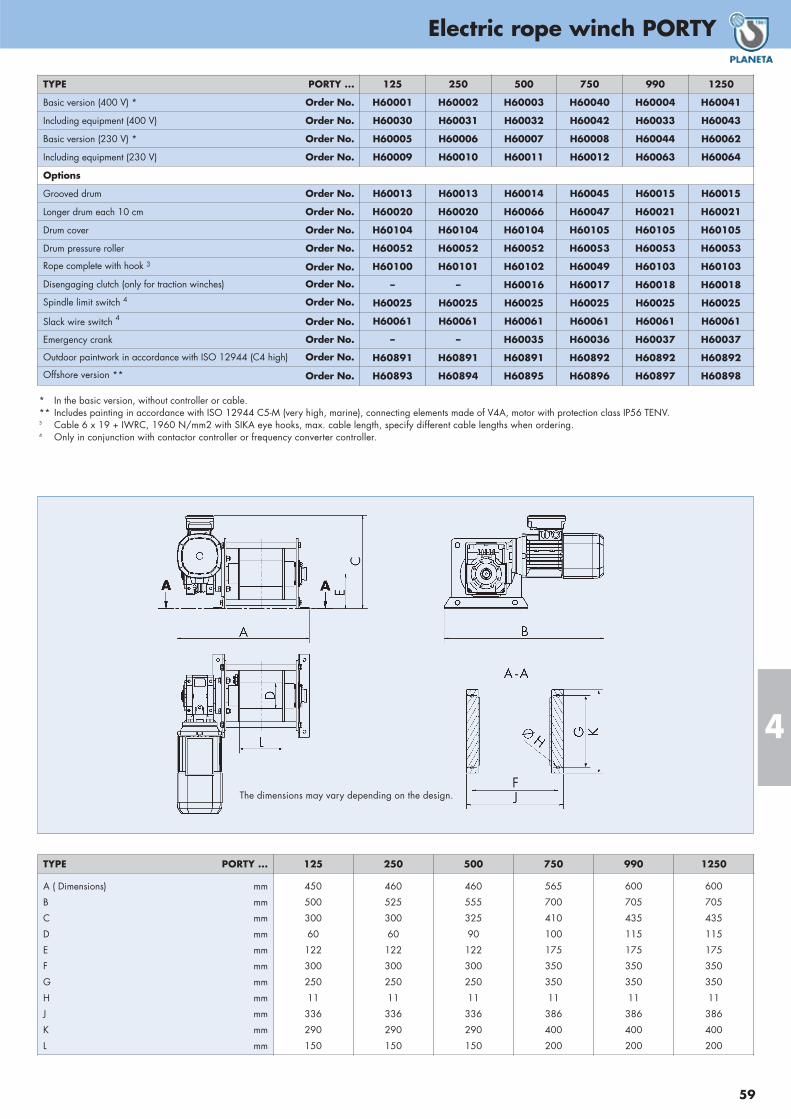
59
Electric rope winch PORTY
4
TYPE PORTY ... 125 250 500 750 990 1250
A ( Dimensions) mm
B mm
C mm
D mm
E mm
F mm
G mm
H mm
J mm
K mm
L mm
450
500
300
60
122
300
250
11
336
290
150
460
525
300
60
122
300
250
11
336
290
150
460
555
325
90
122
300
250
11
336
290
150
565
700
410
100
175
350
350
11
386
400
200
600
705
435
115
175
350
350
11
386
400
200
600
705
435
115
175
350
350
11
386
400
200
The dimensions may vary depending on the design.
* In the basic version, without controller or cable. ** Includes painting in accordance with ISO 12944 C5-M (very high, marine), connecting elements made of V4A, motor with protection class IP56 TENV. 3 Cable 6 x 19 + IWRC, 1960 N/mm2 with SIKA eye hooks, max. cable length, specify different cable lengths when ordering.4 Only in conjunction with contactor controller or frequency converter controller.
TYPE PORTY ... 125 250 500 750 990 1250
Basic version (400 V) * Order No. H60001 H60002 H60003 H60040 H60004 H60041
Including equipment (400 V) Order No. H60030 H60031 H60032 H60042 H60033 H60043
Basic version (230 V) * Order No. H60005 H60006 H60007 H60008 H60044 H60062
Including equipment (230 V) Order No. H60009 H60010 H60011 H60012 H60063 H60064
Options
Grooved drum Order No. H60013 H60013 H60014 H60045 H60015 H60015
Longer drum each 10 cm Order No. H60020 H60020 H60066 H60047 H60021 H60021
Drum cover Order No. H60104 H60104 H60104 H60105 H60105 H60105
Drum pressure roller Order No. H60052 H60052 H60052 H60053 H60053 H60053
Rope complete with hook 3 Order No. H60100 H60101 H60102 H60049 H60103 H60103
Disengaging clutch (only for traction winches) Order No. – – H60016 H60017 H60018 H60018
Spindle limit switch 4 Order No. H60025 H60025 H60025 H60025 H60025 H60025
Slack wire switch 4 Order No. H60061 H60061 H60061 H60061 H60061 H60061
Emergency crank Order No. – – H60035 H60036 H60037 H60037
Outdoor paintwork in accordance with ISO 12944 (C4 high) Order No. H60891 H60891 H60891 H60892 H60892 H60892
Offshore version ** Order No. H60893 H60894 H60895 H60896 H60897 H60898

Electric wormgear winches MCW-Series
60
4
TYPE
Max. pulling force1st rope layer
daN
Max. pulling force
5th rope layerdaN
Max. lifting capacity1st rope layer
kg
Max. lifting capacity5th rope layer
kg
Recomm.rope diam.
mm
Speed1st layer
m/min.
Drum storage1st layer
m
Drum storage5th layer
m
Motor power400 VkW. S2
Weightwithout rope
kg
MCW 250
MCW 500
MCW 750
MCW 1200
MCW 1700
MCW 2200
250
500
750
1200
1700
2200
170
340
490
750
1055
1365
200
400
600
960
1300
1700
135
275
390
600
805
1055
6
6
7
8
10
12
6
6
6
5
6
7
2
2
6
5
7
9
19
19
42
38
50
63
0.75
1.1
1.5
2.2
4
5.5
22
35
55
92
140
180
TYPE MCW (400 Volt)
MCW
MCW-SeriesA range of electric self braking worm gear winches, developed forheavy duty pulling and traversing duties up to 2200 kg. Due to theself braking worm gears the winches are suitable for pulling up anincline. A brake is available as an option for accurate positioningor repetitive lifting applications up to 2000 kg. MCW-series oftenused to rank railway waggons, bring motorless cars and trucks into repair workshops or tows fresh fallen timber. The winches canbe used with 100% ED, which means continuesly. We alwaysrecommend to use the version with three phase motors to enablebetter starting with attached hanging loads.
Complete executionThe package contains the winch with brake motor, a control boxand a emergency stop button, 3 m power cable with connector,however without rope.
SafetySafety is always important when loads are moved. Therefore MCWhave an overload protection in the control box and a redemergency-stop button either on the control box cover or at thehandheld pendant control.
Standard features• Self braking worm gear transmission
• IP 54 aluminium non braked motor 400 V AC / 3 phase / 50 Hz
• Steel drum (not grooved) with cable fixing point at flange
• Single drum support (MC 250, MC 500)
• Two drum supports (all other models)
• Double layer 2 component conservation, colour RAL 5010
Available options• Braked motor (aluminium or cast iron)
• IP 56 TENV cast iron motor for marine applications
• 230 V single phase motors (up to MC 750)
• 24 V DC motors
• Explosion proof motors
• Protective steel motor cover
• Manual or remotely controlled disengaging clutch
• Band brakes
• Grooved drum
• Drum guards
• Emergency cranking
• Marine /offshore coating systems
• Drum pressure roller
• Alternative drum dimensions / split drums /additional rope anchors /etc.
• Emergency cranking
Available control options• Direct pendant remote control IP 65 with emergency stop
(up to 1.5 kW 230 V AC / 1 phase or 2.2 kW 400 V AC /3 phase)
• Control box IP 55 with pushbuttons and emergency stop
• Control box IP 55 with low voltage IP 65 remote control
• Load limiter
• Frequency inverter for variable speed control
• Wireless radio remote control systems
• Limit switches
• Slack wire rope switches
• Alternative speeds
• Limit switches
• Slack wire rope switches
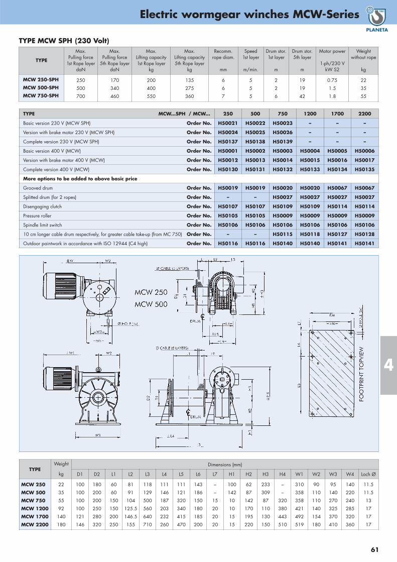
61
Electric wormgear winches MCW-Series
4
TYPE
Max. Pulling force
1st Rope layerdaN
Max. Pulling force
5th Rope layerdaN
Max. Lifting capacity1st Rope layer
kg
Max. Lifting capacity5th Rope layer
kg
Recomm.rope diam.
mm
Speed1st layer
m/min.
Drum stor.1st layer
m
Drum stor.5th layer
m
Motor power
1-ph/230 VkW S2
Weightwithout rope
kg
MCW 250-SPH
MCW 500-SPH
MCW 750-SPH
250
500
700
170
340
460
200
400
550
135
275
360
6
6
7
5
5
5
2
2
6
19
19
42
0.75
1.5
1.8
22
35
55
TYPE MCW SPH (230 Volt)
TYPEWeight
kg
Dimensions (mm)
D1 D2 L1 L2 L3 L4 L5 L6 L7 H1 H2 H3 H4 W1 W2 W3 W4 Loch Ø
MCW 250
MCW 500
MCW 750
MCW 1200
MCW 1700
MCW 2200
22
35
55
92
140
180
100
100
100
100
121
146
180
200
200
250
280
320
60
60
150
150
200
250
81
91
104
125.5
146.5
155
118
129
500
560
640
710
111
146
187
203
232
260
111
121
320
340
415
470
143
186
150
180
185
200
–
–
15
20
20
20
100
142
10
10
15
15
62
87
142
170
195
220
233
309
87
110
130
150
–
–
320
380
443
510
310
358
358
421
492
519
90
110
110
140
154
180
95
140
270
325
370
410
140
220
240
285
320
360
11.5
11.5
13
17
17
17
TYPE MCW...SPH / MCW... 250 500 750 1200 1700 2200
Basic version 230 V (MCW SPH) Order No. H50021 H50022 H50023 – – –
Version with brake motor 230 V (MCW SPH) Order No. H50024 H50025 H50026 – – –
Complete version 230 V (MCW SPH) Order No. H50137 H50138 H50139 – – –
Basic version 400 V (MCW) Order No. H50001 H50002 H50003 H50004 H50005 H50006
Version with brake motor 400 V (MCW) Order No. H50012 H50013 H50014 H50015 H50016 H50017
Complete version 400 V (MCW) Order No. H50130 H50131 H50132 H50133 H50134 H50135
More options to be added to above basic price
Grooved drum Order No. H50019 H50019 H50020 H50020 H50067 H50067
Splitted drum (for 2 ropes) Order No. – – H50027 H50027 H50027 H50027
Disengaging clutch Order No. H50107 H50107 H50109 H50109 H50114 H50114
Pressure roller Order No. H50105 H50105 H50009 H50009 H50009 H50009
Spindle limit switch Order No. H50106 H50106 H50106 H50106 H50106 H50106
10 cm longer cable drum respectively, for greater cable take-up (from MC 750) Order No. – – H50115 H50118 H50127 H50128
Outdoor paintwork in accordance with ISO 12944 (C4 high) Order No. H50116 H50116 H50140 H50140 H50141 H50141

Compact rope winch FD-Series
62
4
Planetary crane winches FD-SeriesSpecially designed for applications where space is at a premium,these compact and lightweight lifting winches are ideally suited forinstallation on cranes, davits and derricks. The single drum supportenables the rope to leave the drum at any angle. The heavy dutyplanetary drive is partly located within and protected by the drumcore. The large drum diameters ensure a healthy drum to cable diameter ratio and sufficient working length despite the short drums.
Standard features• Heavy duty planetary gearbox
• FD E; IP 54 aluminium braked motor 400VAC / 3 phase/ 50 Hz
• FD H; orbit or radial piston type hydraulic motor complete withbrake valve
• FD LPR; radial piston type air motor complete with hand controlvalve and mufflers
• Steel drum with cable fixing point at flange
• Single drum support
• Double layer 2 component conservation, colour RAL 5010
Available options
• IP 56 TENV cast iron motor for marine applications
• Explosion proof motors
• Protective steel motor cover
• Drum pressure roller
• Alternative speeds
• Alternative supply voltages
• Drum guards
• Marine / offshore coating systems
• Tubular offshore frame construction with lifting eyes
Available control options
• Control box IP 55 with pushbuttons and emergency stop
• Control box IP 55 with low voltage IP 65 remote control
• Load limiter (required by CE)
• Frequency inverter for variable speed control
• Wireless radio remote control system
• Limit switches
• Slack wire switches
• Radio / Infra-red remote control
Type FD
TYPE
Max. capacity1st layer
kg
Max. capacitytop layer
kg/layers
Recomm.rope diam.
mm
Speed1st layer
m/min.
Speedtop layer
m/min.
Drum storage1st layer
m
Drum cap.all layers
m/layers
Motor power400 V AC
kW
Order No.
FD 300-E
FD 301-E
FD 303-E
FD 305-E
FD 306-E
FD 307-E
950
1850
2300
3350
4100
5250
800/4
1470/4
1970/3
2800/3
3500/3
4490/3
8
11
12
14
16
18
8.5
9
7
9
7
12
10
11
8.5
11
8.5
14
15
10
11
10
15
18
70/4
53/4
41/3
40/3
56/3
67/3
1.5
3
3
5.5
5.5
11
H50330
H50331
H50332
H50333
H50334
H50335
TYPE FD-Series electric
TYPE
Max. capacity1st layer
kg
Max. capacitytop layer
kg/layers
Recomm.rope diam.
mm
Speed1st layer
m/min.
Speedtop layer
m/min.
Drum cap.1st layer
m
Drum storageall layers
m/layers
Pressuredrop in
bar
Flowin
l/min.
Order No.
FD 300-H
FD 301-H
FD 303-H
FD 305-H
FD 306-H
FD 307-H
950
1850
2300
3350
4100
5250
800/4
1470/4
1970/3
2800/3
3500/3
4490/3
8
11
12
14
16
18
30
20
15
13
13
13
35
25
17
16
15
15
15
10
11
10
15
18
70/4
53/4
41/3
40/3
56/3
67/3
140
130
130
135
140
170
35
55
50
60
70
70
H50336
H50337
H50338
H50339
H50340
H50341
TYPE FD-Series hydraulic

63
Compact rope winch FD-Series
4
FD with angular gear FD with hydraulic motor
TYPE
Max. capacity1st layer
kg
Max. capacitytop layer
kg/layers
Recomm.rope diam.
mm
Speed1st layer
m/min.
Speedtop layer
m/min.
Drum storage1st layer
m
Drum cap.all layers
m/layers
Air pressure
bar
Air consumption
l/sec.
Order No.
FD 300-LPR1
FD 300-LPR2
FD 301-LPR2
FD 303-LPR2
FD 303-LPR3
FD 305-LPR3
FD 306-LPR4
FD 307-LPR4
800
950
1850
2300
2300
3350
4100
5250
675/4
800/4
1470/4
1970/3
1970/3
2800/3
3500/3
4490/3
8
8
11
12
12
14
16
18
8
18
9
7
15
10
15
12
10
21
11
8
18
12
18
14
15
15
10
11
11
10
15
18
70/4
70/4
53/4
41/3
41/3
40/3
56/3
67/3
7
7
7
7
7
7
7
7
30
90
90
90
150
150
225
240
H50342
H50343
H50344
H50345
H50346
H50347
H50348
H50349
TYPE FD-Series pneumatic
TYPEWeight
kg
Dimensions (mm)
D1 D2 L1 L2 L3 L4 (E) L4 (H) L4 (L) L5 L6 H1 H2 W1 W2 Loch-Ø
FD 300
FD 301
FD 303
FD 305
FD 306
FD 307
125
130
175
240
330
590
244
244
272
272
355
406
380
380
410
410
500
625
176
176
191
210
266
310
310
310
350
350
455
510
93
93
106
116
146
175
736
796
818
1030
1100
1313
520
558
595
625
780
885
765
785
905
950
1110
1215
240
240
275
275
350
400
44
44
50
50
70
75
215
215
235
235
285
348
405
405
440
440
535
660
440
440
500
500
580
750
400
400
450
450
520
680
18
18
22
22
27
27

Planetary standard build winches SB-Series
64
4
• SB LG; gear type air motor complete with hand or remote control valve and mufflers
• Steel drum with cable fixing point at flange • Two drum supports• Double layer 2 component conversation, colour RAL 5010
Available winch options• IP 56 TENV cast iron motor for marine applications• Alternative drum dimensions / split drums /
additional rope anchors /etc.• Explosion proof motors• Protective steel motor cover• Drum pressure roller, spooling gears, grooved drums• Band brakes (manual or failsafe automatic)• Manual disengaging clutch• Alternative speeds• Alternative supply voltages• Drum guards• Manual emergency crank• Slip ring mounting• Warping head• Angular gear
Available control options:• Control box IP 55 with pushbuttons and emergency stop• Control box IP 55 with low voltage IP 65 remote control • Load limiter (required by CE for applications exceeding
1000 kg W.L.L.)• Frequency inverter for variable speed control• Wireless radio remote control systems• Limit switches (electric, pneumatic)• Slack wire switches (electric, pneumatic)• Proportional local or remote control valve (pneumatic or hydraulic)• Motor overheating protection
SB-SeriesThe standard build SB type winch provides the basis of the solutionto many pulling and lifting winch applications. The winch is con-structed in the conventional manner with motor, gearbox and drumin line. When it comes to the need of a shorter design the SB winchis available with a angular gearbox. The choice of the rope com-plies with the pulling force in the 5th rope layer. The drum is buildaccording classification 1Am. The drum diameter is at least 16-times bigger than the diameter of the indicated rope diameter.Although the name of this winch indicates different, these winchesare very suitable to fit to your specific winch application and canbe equipped with different drums, other gearboxes or motors.Many options can be offered on these highly versatile winches. The standard version comes without a rope and control.
Standard winch features:• Heavy duty planetary gearbox• SB E; IP 54 aluminium braked motor 400VAC / 3phase / 50 Hz• SB H; orbit or radial piston type hydraulic motor complete with
brake valve• SB LPR; radial piston type air motor complete with hand control
valve and mufflers
Type SB 304-E with angular gearbox and manual free spooling clutch
TYPE
Lifting capacity1st layer
kg
Lifting capacity5th layer
kg
Recommended rope diameter
mm
Rope speed1st layer
m/min.
Rope speed5th layer
m/min.
Drum storage1st layer
m
Drum storage5th layer
m
Oil pressuredrop in
bar
Oil flowin
l/min.
Order No.
SB 303-HSB 305-HSB 306-HSB 307-HSB 309-HSB 310-HSB 311-HSB 313-HSB 315-HSB 316-H
250040005500700090001200016000200003050037000
174027703970496062858460
10655136102080024570
14161822262834384448
18182520131110886
2626352818161512129
26252826242419191917
165161181171163168144151151141
140160225230190230230210235225
608095
10010095
110120165160
H50077H50078H50079H50080H50081H50096H50082H50083H50097H50098
TYPE SB-Series hydraulic
TYPE Lifting capacity
1st layer kg
Lifting capacity5th layer
kg
Recommendedrope diameter
mm
Rope speed1st layerm/min.
Rope speed5th layerm/min.
Drum storage1st layer
m
Drum storage5th layer
m
Motorpower 3-ph
kW
Order No.
SB 300-E SB 301-ESB 304-ESB 305-ESB 306-ESB 307-ESB 309-ESB 310-ESB 311-ESB 313-ESB 314-ESB 315-ESB 316-E
1250200030004000550070009000120001500018000230003000037000
8751400210028003800490063008400
1040012400160002040024500
9111416192224283234384448
8.58.58.5888
108
7.56666
12.512.512.511.511.511.514
11.5119999
24242424242424242322222018
155155155155155155155155154153153145137
2.23
5.55.57.51115
18.52222303045
H50091H50092H50175H50071H50072H50073H50074H50093H50075H50076H50177H50094H50095
TYPE SB-Series electric
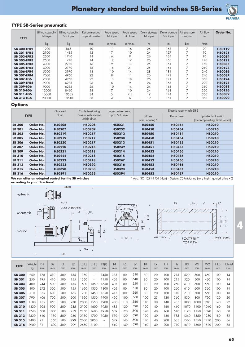
65
Planetary standard build winches SB-Series
4
TYPE
Lifting capacity1st layer
kg
Lifting capacity5th layer
kg
Recommended rope diameter
mm
Rope speed1st layer
m/min.
Rope speed5th layer
m/min.
Drum storage1st layer
m
Drum storage5th layer
m
Air pressuredrop in
bar
Air flowin
l/min.
Order No.
SB 300-LPR2SB 301-LPR2SB 303-LPR2SB 303-LPR3SB 305-LPR3SB 305-LPR4SB 306-LPR4SB 307-LPR4SB 307-LG6SB 309-LPR4SB 309-LG6SB 310-LG6SB 311-LG6SB 313-LG6
12002100250025004000400055007000700090009000120001600020000
84514351740174027702770397049604960628562858460
1065513610
1012141416161822222626283438
1176
129
15108
136
10754
16109
1713211411189
14107.56
2624262625252826262424241919
168157165165161161181171171163163168144151
77777777777777
909090
140150240240240350220350350350350
H50119H50121H50084H50122H50085H50123H50086H50087H50124H50125H50088H50126H50089H50090
TYPE SB-Series pneumatic
TYPEGrooved
drumCable tensioning
device with scoredcable drum
Longer cable drum, up to 500 mm
Electric rope winch SB-E
3-layer paint coating*
Drum cover Spindle limit switch (as an operating limit switch)
SB 300 Order No. H50206 H50208 H50231 H50450 H50454 H50210SB 301 Order No. H50207 H50209 H50232 H50450 H50454 H50210SB 303 Order No. H50219 H50217 H50212 H50450 H50454 H50210SB 305 Order No. H50219 H50217 H50238 H50450 H50454 H50210SB 306 Order No. H50220 H50217 H50213 H50451 H50455 H50210SB 307 Order No. H50220 H50218 H50239 H50451 H50455 H50210SB 309 Order No. H50221 H50218 H50214 H50452 H50456 H50210SB 310 Order No. H50222 H50218 H50215 H50452 H50456 H50210SB 311 Order No. H50222 H50218 H50247 H50452 H50456 H50210SB 313 Order No. H50223 H50392 H50216 H50452 H50456 H50210SB 315 Order No. H50390 H50233 H50393 H50453 H50457 H50210SB 316 Order No. H50391 H50233 H50394 H50453 H50457 H50210
Options
* Acc. ISO 12944 C4 (high) – System C5-M-Marine (very high), quoted price x 2We can offer an adapted control for the SB winchesaccording to your directions!
TYPEWeight
kgD1mm
D2mm
L1mm
L2mm
L3(E)mm
L3(H)mm
L3(P)mm
L4mm
L6mm
L7mm
L8mm
L9mm
H1mm
H2mm
H3mm
W1mm
W2mm
HEBmm
Hole Ømm
SB 300SB 301SB 303SB 305SB 306SB 307SB 309SB 310SB 311SB 313SB 315SB 316
250250400400510790110014201740232034002900
178195244272355406455508508610711711
4104105005006007008509001000115013501400
500500500500500500500500500500500500
135155155155165200230235259260299299
135013501600165017001950200021002150215026002650
––
1350135014501550155016001600170020502100
1450145016501800185019001900195019501950
––
385405405405415450480485509510549549
8080808080
100110120120120140140
540540550550560560560590590590590590
8080808080
100110120120120140140
202020202025304040404040
100100100100100120140160160180200200
215215260260310360435460510585685710
520520610610710830
100010701170134015601610
500500600600700800
100011001150135015501600
460460560560660750940
10401090128014701520
100100100100100120140160160180200200
141414141820222630323636

Wormgear winches MC-L / MC-H
66
4
Hydraulic wormgear winch MC-H-SeriesA range of hydraulic selfbraking wormgear winches, developedfor heavy duty lifting and pulling applications up to 2500 kg.Due to the modular concept and the flexibility of our production itis possible to build, within short delivery times, many variationsof these winches such that they may be adapted to your specificneeds. The types H 500 and H 700 are constructed without a brakeand are designed to be totally self braking. The types H 1200 toH 2500 are designed with a failsafe brake and brake valve.Control of oil flow is normally done by power pack. But if it isprefered to be aside the winch, we can provide a control handleat the motor, too.
Standard features• Wormgear transmission• Orbitmotor• Steel drum (not grooved) with cable fixing point at flange• Single drum support (H 500)• Two drum supports (all other models)• Double layer 2 component conservation, colour RAL 5010• Brake and double acting brake valve (not on H 500, H 700)
Available options• Manual disengaging clutch• Bandbrakes, manual or automatic fail safe• Grooved drum• Drum pressure roller• Alternative speeds• Alternative drum dimensions / split drums /
additional rope anchors / etc.• Drum guard• Emergency cranking• Marine / offshore coating systems• Proportional control valves• Hydraulic power packs
Option:
MC-H 1200
Free spooling clutch
Pneumatic wormgear winch MC-L-SeriesFor pneumatic winch applications, demanding a lightweight con-struction, this range of explosion proof winches provides the solution.The use of vane type motors and inherently safe self braking wormgears ensures trouble free operation and low maintenance require-ments. These winches find their use in general industry, oil and gas exploration and in many places where compact, explosion proofhoisting gear is required. The self braking characteristics of the worm gear drive combinedwith closed ports is sufficient for almost all hoisting purposes. An extra brake may be necessary for accurate positioning of load.
Standard features• Self braking worm gear transmission• Rotary vane motor• Steel drum (not grooved) with cable fixing point at flange• Two drum supports• Double layer 2 component conservation, colour RAL 5010
Available options• Manual disengaging clutch• Band brake, manual or automatic fail safe• Grooved drum• Drum pressure roller• Alternative speeds• Alternative drum dimensions / split drums /
additional rope anchors / etc.• Drum guard• Emergency cranking• Marine / offshore coating systems• Proportional control valve, local or remote• Pneumatic limit switch• Pneumatic slack wire switch
MC-L 1250

67
Wormgear winches MC-L / MC-H
4
TYPEWeight
kg
Dimensions (mm)
D1 D2 L1 L2 L3 L4 L5 L6 L7 H1 H2 H3 H4 W1 W2 W3 W4 Hole Ø
MC-H 500
MC-H 700
MC-H 1200
MC-H 2000
MC-H 2500
35
50
82
134
170
100
100
121
159
178
200
200
250
280
320
60
150
150
200
250
91
104
125.5
146.5
155
–
500
560
640
710
146
187
203
232
280
121
320
340
415
470
186
150
180
185
200
–
15
20
20
20
142
10
10
15
15
87
142
170
195
220
289
87
110
130
150
–
309
354
440
510
253
253
400
456
467
110
110
140
154
180
140
270
325
370
410
220
240
285
320
360
11.5
13
17
17
17
TYPEWeight
kg
Dimensions (mm)
D1 D2 L1 L2 L3 L4 L5 L6 L7 H1 H2 H3 H4 W1 W2 W3 W4 Hole Ø
MC-L 425
MC-L 750
MC-L 1250
MC-L 1700
59
93
149
192
100
121
146
159
200
250
280
320
150
150
200
250
105
125.5
146.5
155
500
560
640
710
187
203
232
260
320
340
415
470
150
180
185
200
15
20
20
20
10
10
15
15
142
170
195
220
87
110
130
150
389
390
440
510
374
455
490
609
110
140
154
180
270
325
370
410
240
285
320
360
13
17
17
17
TYPE Pneumatic wormgear winch MC-L ... 425 750 1250 1700
Max. Lifting capacity in 1st rope layer kgMax. Lifting capacity in 3rd rope layer kgRecommended rope diameter mmRope speed in 1st rope layer m/minUsable rope length in 1st rope layer mUsable rope length in 3rd rope layer mAir pressure barAir consumption with full load l/sec.
425350
657
266
20
750600
85,56
236
60
12501000
1069
326
95
17001325
127
10356
140
MC-L ... with lever control Order No. H50034 H50036 H50038 H50269
TYPE Hydraulic wormgaer winch MC-H ... 500 700 1200 2000 2500
Max. Lifting capacity in 1st rope layer kgMax. Lifting capacity in 3rd rope layer kgRecommended rope diameter mmRope speed in 1st rope layer m/minUsable rope length in 1st rope layer mUsable rope length in 3rd rope layer mPressure barOil volume l/min
500400
66.52
105020
700540
86.55
206020
1200940
995
219550
20001560
12108
2810560
25001965
13119
3613060
MC-H ... without control Order No. H50044 H50045 H50046 H50047 H50048

Capstans E/H/C-Series
68
4
E/H/C-SeriesWormgear capstansSelfbraking worm gear drives with electric, hydraulic or even pneumatic motor, available in on-deck or below-deck build types.The on-deck drive is equipped with a waterproof motor for intermittent use. The below-deck drive is equipped with a dripwater proof motor and a mounting plate with extra self aligning bearing suitable for high static loads such as with mooringropes. Pneumatic drives are available upon request.
Planetary capstansFeaturing a cast iron capstan head mounted on a heavy duty planetary gearbox. The entire drive is mounted in a watertight tubeframe providing optimal protection from the elements. Pneumaticdrives are available upon request. Capstans up to 15 ton can beoffered upon request.
Standard features• Heavy duty worm gearbox or planetary gearbox
• IP 54 aluminium braked motor 400VAC / 3 phase / 50 Hz forplanetary capstans
• IP 56TENV cast iron unbraked motor 400VAC / 3 phase / 50 Hz for on-deck worm gear capstans
• IP 54 unbraked motor 400VAC / 3 phase / 50 Hz for under-deck worm gear capstans
• Single speed and one direction only (electric capstans only)
• Orbit or radial piston type hydraulic motor
• Vertical cast iron warping head
• Double layer 2 component conservation, colour RAL 5010
Available options• Cast iron motor for planetary capstans
• Explosion proof motors
• Back stop bearing build in planetary gearbox for one direction(replaces brake)
• 2 speed motors
• Alternative speeds
• Alternative supply voltages
• Horizontal warping head configuration
• Marine / offshore coating systems
Available control options• Control box IP 55 with IP 65 foot pedal (single speed,
one direction) control
• Control box IP 55 with IP 65 foot pedal (two speed, two directions) control
• Frequency inverter and proportional foot pedal for variablespeed control
• Proportional local or remote control valve (pneumatic orhydraulic)
TYPEMax.
pulling capacitykg
Rope speed
m/min.
Neckdiameter
mm
Max.Rope diam.
mm
Motor power3-ph / 400 V
kW
Oil pressuredrop in
bar
Oil flowin
l/min.
Order No.
C 086-E
C 110-E
C 130-E
C 150-E
C 185-E
500
700
1100
1300
1700
6
11
9
13
10
100
140
140
195
195
18
25
25
35
35
1.1
2.2
3
5.5
5.5
–
–
–
–
–
–
–
–
–
–
H50360
H50361
H50362
H50363
H50364
C 086-H
C 110-H
C 130-H
C 150-H
C 185-H
500
700
1100
1300
1800
8
8
7
10
10
100
140
140
195
195
18
25
25
35
35
–
–
–
–
–
70
105
60
90
90
20
15
40
40
60
H50365
H50366
H50367
H50368
H50369
TYPE E/H/C-Series worm
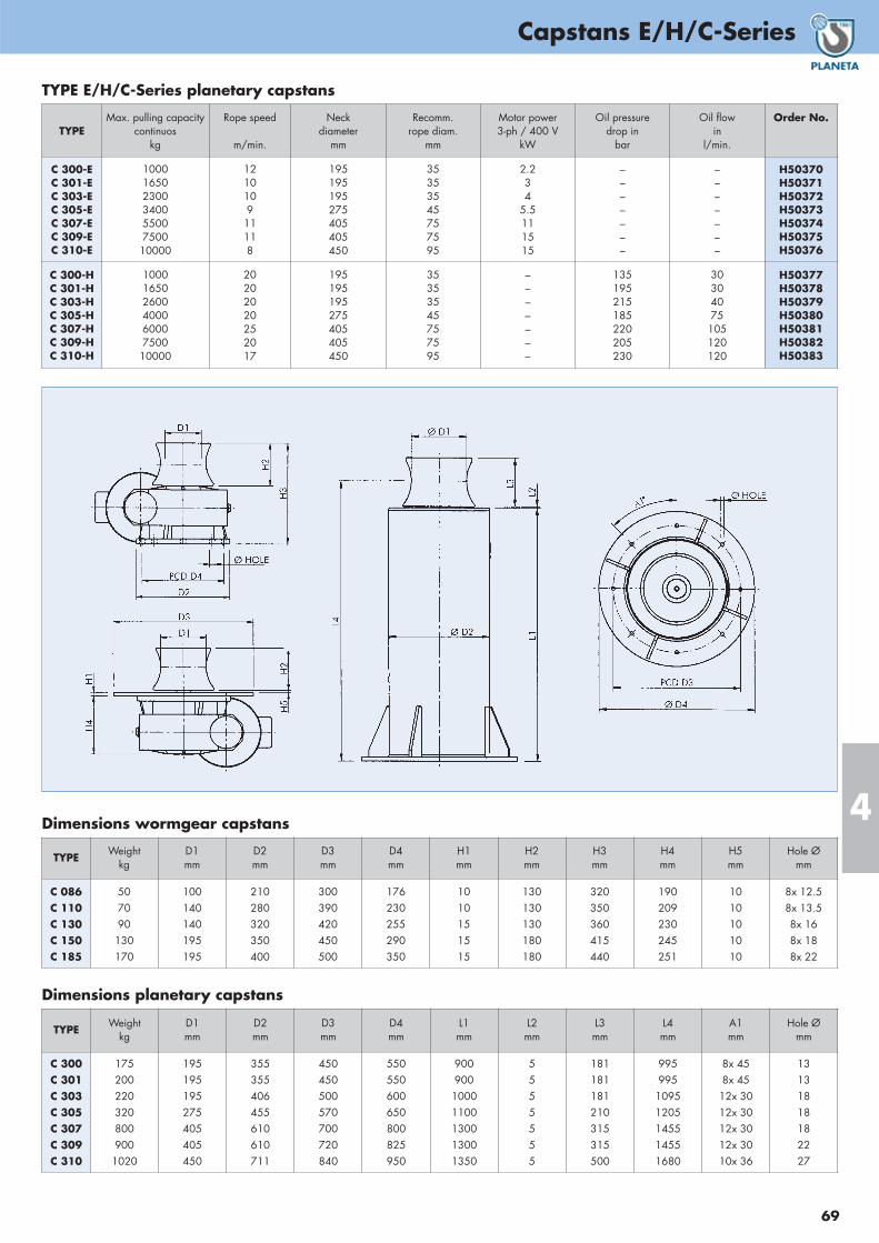
69
Capstans E/H/C-Series
4
TYPEMax. pulling capacity
continuoskg
Rope speed
m/min.
Neckdiameter
mm
Recomm.rope diam.
mm
Motor power3-ph / 400 V
kW
Oil pressuredrop in
bar
Oil flowin
l/min.
Order No.
C 300-EC 301-EC 303-EC 305-EC 307-EC 309-EC 310-E
10001650230034005500750010000
1210109
11118
195195195275405405450
35353545757595
2.234
5.5111515
–––––––
–––––––
H50370 H50371 H50372 H50373 H50374 H50375 H50376
C 300-HC 301-HC 303-HC 305-HC 307-HC 309-HC 310-H
10001650260040006000750010000
20202020252017
195195195275405405450
35353545757595
–––––––
135195215185220205230
30304075
105120120
H50377 H50378 H50379 H50380 H50381 H50382 H50383
TYPE E/H/C-Series planetary capstans
TYPEWeight
kgD1mm
D2mm
D3mm
D4mm
H1mm
H2mm
H3mm
H4mm
H5mm
Hole Ømm
C 086C 110C 130C 150C 185
507090130170
100140140195195
210280320350400
300390420450500
176230255290350
1010151515
130130130180180
320350360415440
190209230245251
1010101010
8x 12.58x 13.58x 168x 188x 22
Dimensions wormgear capstans
TYPEWeight
kgD1mm
D2mm
D3mm
D4mm
L1mm
L2mm
L3mm
L4mm
A1mm
Hole Ømm
C 300C 301C 303C 305C 307C 309C 310
1752002203208009001020
195195195275405405450
355355406455610610711
450450500570700720840
550550600650800825950
900900
10001100130013001350
5555555
181181181210315315500
995995
10951205145514551680
8x 458x 45
12x 3012x 3012x 3012x 3010x 36
13131818182227
Dimensions planetary capstans

Manual rope winches
70
4
BHW-2600BHW-1800BHW-1200
All gear parts are galvanized, very durableand corrosion resistant in normal weatherconditions.
BHW-1200complete with rope and hook, ready to use.
* Standard rope length
Brake winch BHWThe moderately priced BHW winch is a technical solution to liftand pull loads up to 1.2 tons. The winch has to be fixed with afoot plate by bolts on a solid pedestal. Then the crank can beturned freely in both directions.
Winches in stainless steel upon request.
Features:
• Zinc plated or yellow stove-enamelling protection (optional)• Dismountable hand crank• Automatic load-pressure brake• Gear and brake in closed housing• Double ratchet dog system• Rope easy to assemble
TYPE BHW-1200 BHW-1800 BHW-2600
Max. pulling force bottom (1st) cable layer daNMax. pulling force top (9th) cable layer daNDrum diameter mmGearing ratioLift per crank handle rotation mmLever force daNRope diameter (Construction 2160 N/mm2) mmStandard rope length mPlate size L x B mmLochabstand L x B / Ø mmA ( Dimensions) mmB mmC mmD mmE mmF mmG mmH mmWeight without rope kg
55020047.84.2:135155
20140 x 88
95 x 40 / 1015618488
21027
27251
1093.7
82030057.75:135227
20194 x 107
135 x 70 / 1020325610731927
28360
1097.7
1.20047575.710:125198
20240 x 127
162 x 77 / 1021629312731927
30563
10910.1
BHW... (without rope) zinc galvanized Order No. H30024 H30026 H30028
BHW... complete with rope and hook * Order No. H30041 H30042 H30043

71
5
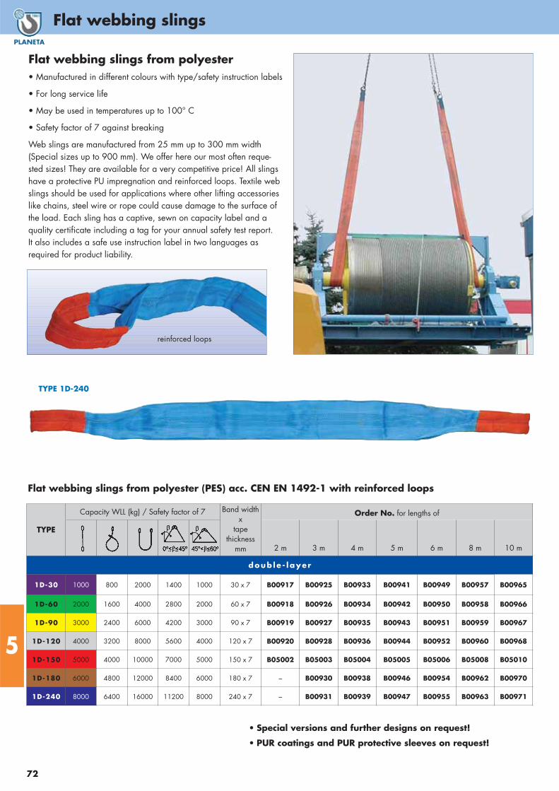
Flat webbing slings
72
5
• Manufactured in different colours with type/safety instruction labels
• For long service life
• May be used in temperatures up to 100° C
• Safety factor of 7 against breaking
Web slings are manufactured from 25 mm up to 300 mm width (Special sizes up to 900 mm). We offer here our most often reque-sted sizes! They are available for a very competitive price! All slingshave a protective PU impregnation and reinforced loops. Textile webslings should be used for applications where other lifting accessorieslike chains, steel wire or rope could cause damage to the surface ofthe load. Each sling has a captive, sewn on capacity label and a quality certificate including a tag for your annual safety test report. It also includes a safe use instruction label in two languages as required for product liability.
TYPE 1D-240
Flat webbing slings from polyester
reinforced loops
• Special versions and further designs on request!
• PUR coatings and PUR protective sleeves on request!
Flat webbing slings from polyester (PES) acc. CEN EN 1492-1 with reinforced loops
TYPE
Capacity WLL (kg) / Safety factor of 7 Band widthx
tape thickness
mm
Order No. for lengths of
2 m 3 m 4 m 5 m 6 m 8 m 10 m
doub le - layer
1D-30 1000 800 2000 1400 1000 30 x 7 B00917 B00925 B00933 B00941 B00949 B00957 B00965
1D-60 2000 1600 4000 2800 2000 60 x 7 B00918 B00926 B00934 B00942 B00950 B00958 B00966
1D-90 3000 2400 6000 4200 3000 90 x 7 B00919 B00927 B00935 B00943 B00951 B00959 B00967
1D-120 4000 3200 8000 5600 4000 120 x 7 B00920 B00928 B00936 B00944 B00952 B00960 B00968
1D-150 5000 4000 10000 7000 5000 150 x 7 B05002 B05003 B05004 B05005 B05006 B05008 B05010
1D-180 6000 4800 12000 8400 6000 180 x 7 – B00930 B00938 B00946 B00954 B00962 B00970
1D-240 8000 6400 16000 11200 8000 240 x 7 – B00931 B00939 B00947 B00955 B00963 B00971
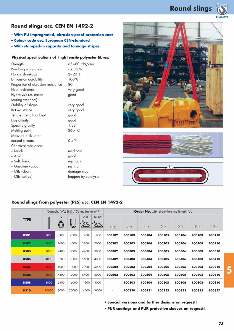
73
Round slings
5
• Special versions and further designs on request!
• PUR coatings and PUR protective sleeves on request!
TYPE
Capacity WLL (kg) / Safety factor of 7 Order No. with circumference length (UL)
2 m 3 m 4 m 5 m 6 m 8 m 10 m
KS01 1000 800 2000 1400 1000 B00102 B00103 B00104 B00105 B00106 B00108 B00110
KS02 2000 1600 4000 2800 2000 B00202 B00203 B00204 B00205 B00206 B00208 B00210
KS03 3000 2400 6000 4200 3000 B00302 B00303 B00304 B00305 B00306 B00308 B00310
KS04 4000 3200 8000 5600 4000 B00402 B00403 B00404 B00405 B00406 B00408 B00410
KS05 5000 4000 10000 7000 5000 B00502 B00503 B00504 B00505 B00506 B00508 B00510
KS06 6000 4800 12000 8400 6000 B00602 B00603 B00604 B00605 B00606 B00608 B00610
KS08 8000 6400 16000 11200 8000 – B00803 B00804 B00805 B00806 B00808 B00810
KS10 10000 8000 20000 14000 10000 – B00830 B00831 B00832 B00833 B00835 B00837
0-45° 45-60°
Round slings from polyester (PES) acc. CEN EN 1492-2
Round slings acc. CEN EN 1492-2
– With PU impregnated, abrasion-proof protection coat – Colour code acc. European CEN-standard– With stamped-in capacity and tonnage stripes
UL
Physical specifications of high tensile polyester fibres:
Strength 65–80 mN/dtexBreaking elongation ca. 12 %Hot-air shrinkage 2–20 %Dimension durability 100 %Proportion of abrasion resistance 80Heat resistance very goodHydrolysis resistance good(during wet heat)Stability of shape very goodRot resistance very goodTensile strength at knot goodDye affinity goodSpecific gravity 1.38Melting point 260 °CMoisture pick-up atnormal climate 0.4 %Chemical resistance:– Leach medicore– Acid good– Salt, basic injurious– Gasoline vapour restistant– Oils (clean) damage may– Oils (soiled) happen by catalysis

Round slings, flat webbing slings and ratchet lashing – sets
74
5
TYPE Order No.
Webbing sling package B00886
PLANETA – ratchet lashing package Ain a practical backpack• In accordance with DIN EN 12 195-2• With ratchet and profile hook A• Made of polyester belt webbing
impregnated with polyurethane• 10-fold higher abrasion resistance• With load capacity label• Tonnage strips woven in
10-piece set comprising:
4 x RG 500 A (2 parts), 25 mm belt width,500 daN pulling force, 6 m length
4 x RG 2000 A (2 parts), 35 mm belt width,2000 daN pulling force, 6 m length
2 x RG 4000 A (2 parts), 50 mm belt width,4000 daN pulling force, 8 m length
Flat webbing slings in a practical sports bag• Lifting straps made of polyester in accordance
with DIN EN 1492-1, with strengthened endstraps
• Colour-coded according to EU standards• Tonnage strips woven in• 7-fold safety• Safety label with user instructions
8-piece set comprising:2 units (1000 kg capacity, 2 m length)2 units (1000 kg capacity, 4 m length)2 units (2000 kg capacity, 2 m length)2 units (2000 kg capacity, 4 m length)
TYPE Order No.
Round sling package B00881
Round sling package in a practical sports bag• Round slings made of polyester in accordance with
DIN EN 1492-2, with double protective sleeve• Colour-coded according to European standards• Load-bearing and tonnage strips woven in• 7-fold safety• Safety label with user instructions
10-piece set comprising:2 units (1000 kg capacity, 2 m circumference length)2 units (1000 kg capacity, 4 m circumference length)2 units (2000 kg capacity, 2 m circumference length)2 units (2000 kg capacity, 4 m circumference length)2 units (3000 kg capacity, 6 m circumference length)
TYPE Order No.
Ratchet lashing package A E00069
PLANETA – ratchet lashing package Bin a practical sports bag
• In accordance with DIN EN 12 195-2
• With ratchet and profile hook A• Made of polyester belt webbing
impregnated with polyurethane
• 10-fold higher abrasion resistance
• With load capacity label
• Tonnage strips woven in
6-piece set comprising:
6 x RG 4000 A (2 parts), 50 mm belt width, 4000 daN pulling force, 8 m length
TYPE Order No.
Ratchet lashing package B E00066
PLANETA – ratchet lashing package Cin a practical sports bag
• In accordance with DIN EN 12 195-2
• With ratchet and profile hook A• Made of polyester belt webbing
impregnated with polyurethane
• 10-fold higher abrasion resistance
• With load capacity label
• Tonnage strips woven in
6-piece set comprising:
6 x RG 5000 A (2 parts), 50 mm belt width, 5000 daN pulling force, 8 m length
TYPE Order No.
Ratchet lashing package C E00067

75
Ratchet Lashing
5
Type DSnap hook
Hook types:
Type CClaw hook C
PUR edge protection plates 35 mm + 50 mm
on request!Type A
Double wire J
TYPE CapacitydaN
Order No.completeL = 4 m
Order No.completeL = 6 m
KG 250 N
KG 500 N
250
500
E00011
E00013
–
E00022
LC LC
250 daN 500 daN
TYPEHook type / Final fittings
two-piece Ratchet lashing hooks
Order No.completeL = 4 m
Order No.completeL = 6 m
RG 500 A
RG 500 N
Type A, Double wire J hook
Endless (without hook)
E00030
E00033
E00035
E00036
two-piece endless
LC LC
250 daN 500 daN
endless endless
� L�
� L�
L
Ratchet lashing Type RG 500 Band width: 25 mm, Fixed end 0.5 m, Loose end 3.5 mRatchet lashing, 4 m or 6 m complete (L)
TYPE Order No.
SPA 55 E00025
openclosed
Tension belt reel for tension belts55 mm max. belt width, max. length 12 m
Cambuckle tie down Type KG 250 and Typ KG 500Band width: 25 mm, Ratchet lashing, 4 m or 6 m complete (L)
Longer lengths on request!
Longer lengths on request!
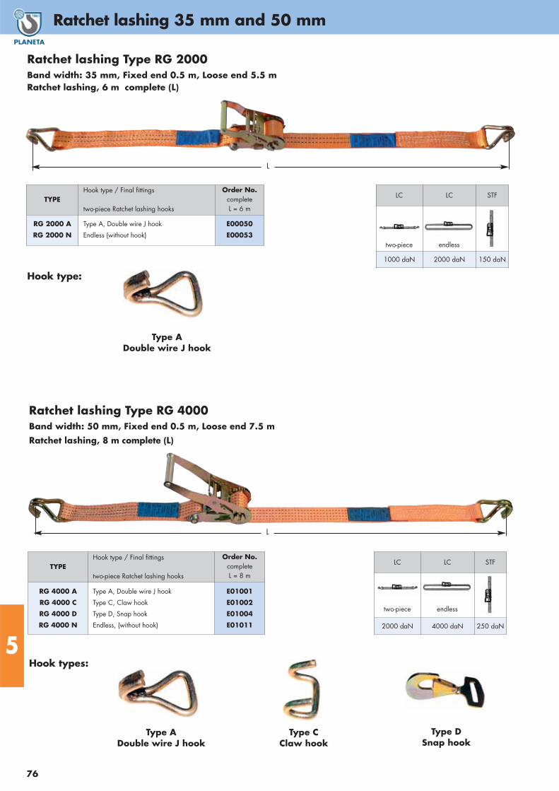
Ratchet lashing 35 mm and 50 mm
76
5
L
LC LC STF
2000 daN 4000 daN 250 daN
TYPEHook type / Final fittings
two-piece Ratchet lashing hooks
Order No.completeL = 8 m
RG 4000 A
RG 4000 C
RG 4000 D
RG 4000 N
Type A, Double wire J hook
Type C, Claw hook
Type D, Snap hook
Endless, (without hook)
E01001
E01002
E01004
E01011
Ratchet lashing Type RG 4000 Band width: 50 mm, Fixed end 0.5 m, Loose end 7.5 m
Ratchet lashing, 8 m complete (L)
two-piece endless
TYPEHook type / Final fittings
two-piece Ratchet lashing hooks
Order No.complete L = 6 m
RG 2000 A
RG 2000 N
Type A, Double wire J hook
Endless (without hook)
E00050
E00053
Ratchet lashing Type RG 2000 Band width: 35 mm, Fixed end 0.5 m, Loose end 5.5 mRatchet lashing, 6 m complete (L)
Hook type:
Hook types:
Type ADouble wire J hook
Type CClaw hook
Type DSnap hook
L
LC LC STF
1000 daN 2000 daN 150 daN
two-piece endless
Type ADouble wire J hook

77
Ratchet lashing 50 mm
5Hook types:
Type ADouble wire J hook
Type CClaw hook
Type DSnap hook
TYPEHook type / Final fittings
two-piece Ratchet lashing hooks
Order No.
completeL = 8 m
RG 5000 A
RG 5000 C
RG 5000 D
RG 5000 N
Type A, Double wire J hook
Type C, Claw hook
Type D, Snap hook
Endless, (without hook)
E01020
E01021
E01023
E01030
LC LC STF
2500 daN 5000 daN 250 daN
two-piece endless
Ratchet lashing Type RG 5000 Band width: 50 mm, Fixed end 0.5 m, Loose end 7.5 m Ratchet lashing, 8 m complete (L)
Ratchet lashing Type RGL 5000 Band width: 50 mm, Fixed end 0.5 m, Loose end 7.5 m Ratchet lashing, 8 m complete (L)
L
L
Hook type:
Type ADouble wire J hook
LC LC STF
2500 daN 5000 daN 500 daN
two-piece endless
TYPEHook type / Final fittings
two-piece Ratchet lashing hooks
Order No.
completeL = 8 m
RGL 5000 A Type A, Double wire J hook E01033
Long Ratchet Lever

Sling chains, grade 8 / grade 10
78
5
SINGLE STRAND DOUBLE STRAND
Load bearingcapacity
t at tilt angle
Chainnominalthickness
1GK8-GKHcompletely
assembled, usablelength: 1 m
Extra lengthper
meter
Shortening per
strand*
Load bearingcapacity
t at tilt angle
Chainnominalthickness
2GK8-GKHcompletely
assembled, usablelength: 1 m
Extra lengthper
meter
Shortening per
strand*
90° Ø mm Order No. Order No. Order No. 0 to 45° 45 to 60° Ø mm Order No. Order No. Order No.
1.12 6 A01250 A01300 A01357 1.6 1.12 6 A01254 A01307 A02357
2 8 A00380 A01301 A01358 2.8 2 8 A00447 A01308 A02358
3.15 10 A00381 A01302 A01359 4.25 3.15 10 A00448 A01309 A02359
5.3 13 A00382 A01303 A01360 7.5 5.3 13 A00449 A01310 A02360
8 16 A00383 A01304 A01361 11.2 8 16 A00450 A01311 A02361
12.5 20 A01253 A01306 A01363 17 12.5 20 A01257 A01313 A02363
Dimension L = usable length
Please specify when ordering!
Dimension L = usable length
Please specify when ordering!
Sling chains DIN EN 818-4, grade 8, completely assembled
* Shortening, consisting of 5 chain links and shortening hook with fork head. Different dimensions or final equipment on request!
TRIPLE STRAND QUADRUPLE STRAND
Load bearingcapacity
t at tilt angle
Chainnominalthickness
3GK8-GKHcompletely
assembled, usablelength: 1 m
Extra lengthper
meter
Shortening per
strand*
Load bearingcapacity
t at tilt angle
Chainnominalthickness
4GK8-GKHcompletely
assembled, usablelength: 1 m
Extra lengthper
meter
Shortening per
strand*
0 to 45° 45 to 60° Ø mm Order No. Order No. Order No. 0 to 45° 45 to 60° Ø mm Order No. Order No. Order No.
2.36 1.7 6 A01262 A01314 A03357 2.36 1.7 6 A01266 A01321 A04357
4.25 3 8 A00514 A01315 A03358 4.25 3 8 A00581 A01322 A04358
6.7 4.75 10 A00515 A01316 A03359 6.7 4.75 10 A00582 A01323 A04359
11.2 8 13 A00516 A01317 A03360 11.2 8 13 A00583 A01324 A04360
17 11.8 16 A00517 A01318 A03361 17 11.8 16 A00584 A01325 A04361
26.5 19 20 A01265 A01320 A03363 26.5 19 20 A01269 A01327 A04363
Dimension L = usable length
Please specify when ordering!
Dimension L = usable length
Please specify when ordering!
SINGLE STRAND DOUBLE STRAND
Load bearingcapacity
t at tilt angle
Chainnominalthickness
1GK10-GKHcompletely
assembled, usablelength: 1 m
Extra lengthper
meter
Shortening per
strand*
Load bearingcapacity
t at tilt angle
Chainnominalthickness
2GK10-GKHcompletely
assembled, usablelength: 1 m
Extra lengthper
meter
Shortening per
strand*
90° Ø mm Order No. Order No. Order No. 0 to 45° 45 to 60° Ø mm Order No. Order No. Order No.
1.4 6 A01364 A01370 A01376 2 1.4 6 A01382 A01388 A01394
2.5 8 A01365 A01371 A01377 3.55 2.5 8 A01383 A01389 A01395
4 10 A01366 A01372 A01378 5.6 4 10 A01384 A01390 A01396
6.7 13 A01367 A01373 A01379 9.5 6.7 13 A01385 A01391 A01397
10 16 A01368 A01374 A01380 14 10 16 A01386 A01392 A01398
14 19 A01369 A01375 A01381 20 14 19 A01387 A01393 A01399
Dimension L = usable length
Please specify when ordering!
Dimension L = usable length
Please specify when ordering!
Sling chains DIN EN 818-4, grade 10, completely assembled

79
Sling chains, grade 10 / grade 12
5
* Shortening, consisting of 5 chain links and shortening hook with fork head. Different dimensions or final equipment on request!
TRIPLE STRAND QUADRUPLE STRAND
Load bearingcapacity
t at tilt angle
Chainnominalthickness
3GK10-GKHcompletely
assembled, usablelength: 1 m
Extra lengthper
meter
Shortening per
strand*
Load bearingcapacity
t at tilt angle
Chainnominalthickness
4GK10-GKHcompletely
assembled, usablelength: 1 m
Extra lengthper
meter
Shortening per
strand*
0 to 45° 45 to 60° Ø mm Order No. Order No. Order No. 0 to 45° 45 to 60° Ø mm Order No. Order No. Order No.
3 2.12 6 A01400 A01406 A01412 3 2.12 6 A01418 A01424 A01430
5.3 3.75 8 A01401 A01407 A01413 5.3 3.75 8 A01419 A01425 A01431
8 6 10 A01402 A01408 A01414 8 6 10 A01420 A01426 A01432
14 10 13 A01403 A01409 A01415 14 10 13 A01421 A01427 A01433
21.2 15 16 A01404 A01410 A01416 21.2 15 16 A01422 A01428 A01434
30 21.2 19 A01405 A01411 A01417 30 21.2 19 A01423 A01429 A01435
Dimension L = usable length
Please specify when ordering!
Dimension L = usable length
Please specify when ordering!
Sling chains DIN EN 818-4, grade 10, completely assembled
SINGLE STRAND DOUBLE STRAND
Load bearingcapacity
t at tilt angle
Chainnominalthickness
1GK12-GKHcompletely
assembled, usablelength: 1 m
Extra lengthper
meter
Shortening per
strand*
Load bearingcapacity
t at tilt angle
Chainnominalthickness
2GK12-GKHcompletely
assembled, usablelength: 1 m
Extra lengthper
meter
Shortening per
strand*
90° Ø mm Order No. Order No. Order No. 0 to 45° 45 to 60° Ø mm Order No. Order No. Order No.
2.36 7 A01436 A01440 A01444 3.35 2.36 7 A01448 A01452 A01456
3 8 A01437 A01441 A01445 4.25 3 8 A01449 A01453 A01457
5 10 A01438 A01442 A01446 7.1 5 10 A01450 A01454 A01458
8 13 A01439 A01443 A01447 11.2 8 13 A01451 A01455 A01459
Dimension L = usable length
Please specify when ordering!
Dimension L = usable length
Please specify when ordering!
Sling chains DIN EN 818-4, grade 12, completely assembled
TRIPLE STRAND QUADRUPLE STRAND
Load bearingcapacity
t at tilt angle
Chainnominalthickness
3GK12-GKHcompletely
assembled, usablelength: 1 m
Extra lengthper
meter
Shortening per
strand*
Load bearingcapacity
t at tilt angle
Chainnominalthickness
4GK12-GKHkcompletely
assembled, usablelength: 1 m
Extra lengthper
meter
Shortening per
strand*
0 to 45° 45 to 60° Ø mm Order No. Order No. Order No. 0 to 45° 45 to 60° Ø mm Order No. Order No. Order No.
5 3.55 7 A01460 A01464 A01468 5 3.55 7 A01472 A01476 A01480
6.3 4.5 8 A01461 A01465 A01469 6.3 4.5 8 A01473 A01477 A01481
10.6 7.5 10 A01462 A01466 A01470 10.6 7.5 10 A01474 A01478 A01482
17 11.8 13 A01463 A01467 A01471 17 11.8 13 A01475 A01479 A01483
Dimension L = usable length
Please specify when ordering!
Dimension L = usable length
Please specify when ordering!

Magnetic lifter
80
5
Special featuresAdopted with new generation high energy magnetic material, it has the advantage of high attractive force, small in volume andlight in self weight; easy operating and safe in operation. It is suitable for lifting, handling and pulling up of steel workpiecesand raw material under normal temperature condition without making any mark to the workpieces.
• High safety factor 3.5:1
• Good air gap feature,the rated plain load could still be attractedup even if the gap is smaller than 0.5 mm.
• Easy operating long term attractive force stablity.
• According EN13155 Standard
Finest state of technologyCompact – Light – High Performance
PML
Safety coefficient
3.5
The magnet is activated by changing the lever from left to right. A safety device blocks the lever in MAG-Phase that hinders the accidentely switch to DEMAG.
DEMAGMAG
TYPE Cap.(load)
kg
Dimensions in mm Flat material Round material Weight
kg
Order No.
A B C D E F G H L N
max. Loadkg
min.Thickn.
mm
max.Length
mm
max. Loadkg
min./max.Diameter
mm
max.Length
mm
PML-1
PML-3
PML-6
PML-10
PML-20
100
300
600
1.000
2.000
42
59
87
110
150
50
75
110
137
192
62
92
122
172
230
44
59
70
100
135
28
39
44
68
98
28
44
56
88
115
116
142
178
237
397
68
93
118
164
214
92
164
234
264
380
31
46
58
95
117
100
300
600
1.000
2.000
10
20
25
40
55
1.500
2.000
3.000
3.000
3.000
30
100
200
300
600
10/300
10/300
15/400
25/450
35/600
1.500
2.000
3.000
3.000
3.000
3
10
24
50
125
F00060
F00061
F00062
F00063
F00064
On Off
ON/OFF switch, easy to operate

81
Plate clamps
5
TYPECapacity
tGrip range
in mm Dimensions in mm Weight
ca. kgOrder No.
A B C D E F G H I
VLC-1
VLC-2
VLC-3
VLC-5
1
2
3
5
0 - 22
0 - 30
0 - 35
0 - 50
27
36
40
50
37
46
51
60
125
155
175
224
48
57
60
65
30
31
35
40
260
300
360
410
30
41
45
34
157
194
227
270
66
78
88
96
3.5
5.5
9
16.5
F00001
F00002
F00003
F00004
Type VLC
The standard lifting clamp is used for vertical lifting and turning of steel or metal plates and beams. The lifting clamp is equipped with a safety-locking device, but easily opens with theuse of a grip snap ring. The VLC has a very robust design with re-enforced side plates. To ensure your safety, please be aware of the capacity reduction whenpulling under angle.
VLC
TYPECapacity
tGrip range (D)
in mm Dimensions in mm Weight
ca. kgOrder No.
A B C E F G H
SLC-0.5
SLC-1
SLC-2
SLC-3
SLC-5
0.5
1
2
3
5
0 - 15
0 - 20
0 - 25
0 - 30
0 - 52
30
48
68
74
80
43
63
76
85
90
34.5
51
59
56
65
103
138
164
193
240
10
12
16
20
22
212
294
370
418
450
36
50
52
78
88
2
5
7
15
23
F00050
F00051
F00052
F00053
F00054
Capacity reduction when lifting under different angles
Type SLCThe SLC is a universal clamp for lifting, turning and transporting of flat metal material in all directions. The pivoting clamp combined with an extra suspensionlink, provides a greater degree of freedom and range of motion. A helpful lifting device when two or moreclamps are needed at the same time. To ensure your safetyplease be aware of the capacity reduction when pullingunder angle.
SLC

Hydraulic pallet truck
82
5
Cylinderat QL
HUBFIX 25QL
The new pallet truck release HUBFIXIf you are looking for good features and while maintaining a lowprice then the manual pallet truck type HF25DF is your bestchoice. If you are looking for superior quality that is not matchedby any one else in the industry, then the HF25QL is the bestchoice. The HF25QL still maintains a competitive price, and is thebest fitting truck for forwarders and storehouses! HUBFIX QLSeries is of highest quality with its enforced lifting piston.
All of them include the new QUICKLIFT-Function. The pallettruck lifts double fast compared with normal trucks on the market.Only 4 handle movements are necessary to lift the forks up to 200 mm. You save time and money during work with HUBFIX!
Best roller materialOur pallet trucks can be supplied with different kind of rollers.The tandem fork rollers and steering wheels at type HF are madeof polyurethane and run on ball bearings. That means: smoothoperation, noiseless movement, high wearability, floor protecting,ideal for polished and rough floors.Other rolls from rubber are available as options.
HUBFIX 25DF
Low pump forceAll units are maintenance free with a hydraulic chromium platedpiston pump.
StableThe rugged welded construction and reinforced forks guaranteea safe transport.
No oil changeMaintenance free bearings and the adequate technicalconstruction verify safety, long life and easy operation.
SecureHighest possible accident protection through safety center polewith control lever with three functions:
LIFT – DRIVE – LOWER
Center pole returns automaticly (spring powered) into verticalposition once you release it. Overload protection by specialrelief pressure valve.
HUBFIX 25DF with lifted forks
HUBFIX 25QL with lifted forks
Cylinderat 25DF
Tandem fork rolls from PU
TYPE HF25DF HF25QL
Capacity tLoad rollersDescent rollersRoller materialGuide wheels mmLoad rollers mmH1 mmH2 mmH3 mmH4 mmL1 mmL2 mmB1 mmB2 mmα degreeWeight kg
2.5Tandem
YESSteel with PU or nylon
Ø 180Ø 80
85105
1230430
115037016055010064
2.5Tandem
YESSteel with PU or nylon
Ø 200Ø 80
82123
1235450
115037016053010074
HF with rolls from PU Order No. L00004 L00002
HF with rolls from nylon Order No. L00007 L00008

83
Hydraulic jacks
5
TYPE
Capacity
t
Liftinghight
mm
Additionalwind-outheightmm
Min./Max.height
mm
Weight
kg
Order No.
A3-WH2
A3-WH3
A3-WH5
A3-WH8
A3-WH12
A3-WH15
A3-WH20
A3-WH32
A3-WH50
2
3
5
8
12
15
20
32
50
80
110
110
125
125
140
145
150
155
50
50
60
60
60
60
60
–
–
148 – 278
180 – 340
185 – 355
200 – 385
210 – 395
225 – 425
235 – 440
255 – 405
300 – 480
2.5
3.5
4.5
5.5
7.5
8.5
12
16
33
K00001
K00002
K00003
K00004
K00005
K00006
K00007
K00008
K00009
TYPECapacity
t
Lift of claw
mm
Lift of head
mm
Max. leverforcekg
Weight
kg
Order No.
HM 5
HM 10
HM 25
5
10
25
25 - 230
30 - 260
58 - 273
368 - 573
420 - 650
505 - 720
38
40
40
25
35
102
K00021
K00022
K00023
Hydraulic jack type HMPLANETA hydraulic jacks for repairs, maintenance and installation of heavy machines.
• Compact and stable construction
• Can be used in any position
• Housing revolves 360 degrees
• Protected against overload• According to CE and US standard USA ASME/ANSI B 30/1.1986
• Lowering speed can be accurately adjusted
• Pump lever is removable
Hydraulic jack type A3-WHThe high quality hydraulic cylinder is equipped with a big foot plate for safe stand. The pump lever mechanism works freely,driven by a detachable-collapsible lever with slot-shaped top foruse at the release valve making transportation and storage asimple procedure. The jack top has a corrugated surface and athread for fine adjustment of height. The piston has an overloadsafety device. A3-WH is suitable for automotive and industrialapplications.
A3-WH
5t
10t25t

Mechanical steel jacks
84
5
Special features:• Milled rack, geared wheels,
tempered parts of driving gear.• Suitable for lifting loads of any type
• SIKU folding crank unit incorporating a friction type brake whichholds the load in any position.
• High grade steel for long life and safety.
• According FEM-standard (European Federation for materialhandling)
• Lift either with fixed toe or on clawed head.
• Manufactured according to German Safety Regulations (UVV)and the regulations of German Berufsgenossenschaft. All jackson this page are equipped with SIKU cranks as standard.
• Only a small expenditure of energy is needed to jack up heavyloads.
• Type VSK is equipped with multiple lifting points.
• Lifting claw adjustable in six positions from 64 mm to 615 mm.
• Large base plate.
DIN-Steel Jack Type SKwith lifting body (DIN standard) and foldable safety crank SIKU
DIN-mechanical steel jacks are used to lift loads like machines or trucks. The hand crank isoperated by manual power. They can be used anywhere as long the claw fits under a load.The housings climbs up along a rack and is held in any position by a safety brake whencranking stops. SIKU means non-detachable safety crank for 360 degree turning operation.
DIN-Steel Jack Type VSKClaw detachable and adjustable; with foldable safety crank SIKU
Type VSK is used for lifting, pushing, pressing, moving and supporting of loads. The bigdifference to SK is the possibility to detach the claw and use it in 9 different positions. That is helpfull if the load has high legs and the jack head cannot be applied. Keep in mindthat the claw of any mechanical jack cannot lift as much load as the jack head.
SK
VSK
RAKU
TYPECapacity
t
Hight in downposition
mm
Lifting height
mm
Height of claw
mm
Weight
kg
Order No.with SIKU
SK - 1,5
SK - 3
SK - 5
SK - 10
SK - 20
1.5
3
5
10
20
725
725
725
800
800
350
350
300
300
340
70
75
70
90
95
15
22
28
41.5
60
K00010
K00011
K00012
K00013
K00015
TYPECapacity
t
Hight in downposition
mm
Lifting height
mm
Height of claw(lowest)
mm
Weight
ca. kg
Order No.with SIKU
VSK - 3
VSK - 5
VSK - 10
3
5
10
720
720
792
350
300
300
69
64
85
24.5
34.5
47.5
K00017
K00018
K00019
TYPEFor jacks with capacity
tOrder No.
RAKU 1,5 - 5
RAKU 10 - 20
1.5 - 5
10 - 20
K00020
K00016
Ratchet crank Type RAKUAll jacks on this page can be supplied as an alternative with a tooth by tooth ratchet crank.Ideal for use in confined areas.The handle lifts jack in one winding direction, the other crank movement back hauls newspace. Uses same safety brake as SIKU.
Rack and pinion driven mechanical jacks with lifting body acc. DIN 7355

Notes
. . . . . . . . . . . . . . . . . . . . . . . . . . . . . . . . . . . . . . . . . . . . . . . . . . . . . . . . . . . . . . . . . . . . . . . . . . . . . . . . . . . . . . .
. . . . . . . . . . . . . . . . . . . . . . . . . . . . . . . . . . . . . . . . . . . . . . . . . . . . . . . . . . . . . . . . . . . . . . . . . . . . . . . . . . . . . . .
. . . . . . . . . . . . . . . . . . . . . . . . . . . . . . . . . . . . . . . . . . . . . . . . . . . . . . . . . . . . . . . . . . . . . . . . . . . . . . . . . . . . . . .
. . . . . . . . . . . . . . . . . . . . . . . . . . . . . . . . . . . . . . . . . . . . . . . . . . . . . . . . . . . . . . . . . . . . . . . . . . . . . . . . . . . . . . .
. . . . . . . . . . . . . . . . . . . . . . . . . . . . . . . . . . . . . . . . . . . . . . . . . . . . . . . . . . . . . . . . . . . . . . . . . . . . . . . . . . . . . . .
. . . . . . . . . . . . . . . . . . . . . . . . . . . . . . . . . . . . . . . . . . . . . . . . . . . . . . . . . . . . . . . . . . . . . . . . . . . . . . . . . . . . . . .
. . . . . . . . . . . . . . . . . . . . . . . . . . . . . . . . . . . . . . . . . . . . . . . . . . . . . . . . . . . . . . . . . . . . . . . . . . . . . . . . . . . . . . .
. . . . . . . . . . . . . . . . . . . . . . . . . . . . . . . . . . . . . . . . . . . . . . . . . . . . . . . . . . . . . . . . . . . . . . . . . . . . . . . . . . . . . . .
. . . . . . . . . . . . . . . . . . . . . . . . . . . . . . . . . . . . . . . . . . . . . . . . . . . . . . . . . . . . . . . . . . . . . . . . . . . . . . . . . . . . . . .
. . . . . . . . . . . . . . . . . . . . . . . . . . . . . . . . . . . . . . . . . . . . . . . . . . . . . . . . . . . . . . . . . . . . . . . . . . . . . . . . . . . . . . .
. . . . . . . . . . . . . . . . . . . . . . . . . . . . . . . . . . . . . . . . . . . . . . . . . . . . . . . . . . . . . . . . . . . . . . . . . . . . . . . . . . . . . . .
. . . . . . . . . . . . . . . . . . . . . . . . . . . . . . . . . . . . . . . . . . . . . . . . . . . . . . . . . . . . . . . . . . . . . . . . . . . . . . . . . . . . . . .
. . . . . . . . . . . . . . . . . . . . . . . . . . . . . . . . . . . . . . . . . . . . . . . . . . . . . . . . . . . . . . . . . . . . . . . . . . . . . . . . . . . . . . .
. . . . . . . . . . . . . . . . . . . . . . . . . . . . . . . . . . . . . . . . . . . . . . . . . . . . . . . . . . . . . . . . . . . . . . . . . . . . . . . . . . . . . . .
. . . . . . . . . . . . . . . . . . . . . . . . . . . . . . . . . . . . . . . . . . . . . . . . . . . . . . . . . . . . . . . . . . . . . . . . . . . . . . . . . . . . . . .
. . . . . . . . . . . . . . . . . . . . . . . . . . . . . . . . . . . . . . . . . . . . . . . . . . . . . . . . . . . . . . . . . . . . . . . . . . . . . . . . . . . . . . .
. . . . . . . . . . . . . . . . . . . . . . . . . . . . . . . . . . . . . . . . . . . . . . . . . . . . . . . . . . . . . . . . . . . . . . . . . . . . . . . . . . . . . . .
. . . . . . . . . . . . . . . . . . . . . . . . . . . . . . . . . . . . . . . . . . . . . . . . . . . . . . . . . . . . . . . . . . . . . . . . . . . . . . . . . . . . . . .
. . . . . . . . . . . . . . . . . . . . . . . . . . . . . . . . . . . . . . . . . . . . . . . . . . . . . . . . . . . . . . . . . . . . . . . . . . . . . . . . . . . . . . .
. . . . . . . . . . . . . . . . . . . . . . . . . . . . . . . . . . . . . . . . . . . . . . . . . . . . . . . . . . . . . . . . . . . . . . . . . . . . . . . . . . . . . . .
. . . . . . . . . . . . . . . . . . . . . . . . . . . . . . . . . . . . . . . . . . . . . . . . . . . . . . . . . . . . . . . . . . . . . . . . . . . . . . . . . . . . . . .
. . . . . . . . . . . . . . . . . . . . . . . . . . . . . . . . . . . . . . . . . . . . . . . . . . . . . . . . . . . . . . . . . . . . . . . . . . . . . . . . . . . . . . .
. . . . . . . . . . . . . . . . . . . . . . . . . . . . . . . . . . . . . . . . . . . . . . . . . . . . . . . . . . . . . . . . . . . . . . . . . . . . . . . . . . . . . . .
. . . . . . . . . . . . . . . . . . . . . . . . . . . . . . . . . . . . . . . . . . . . . . . . . . . . . . . . . . . . . . . . . . . . . . . . . . . . . . . . . . . . . . .
. . . . . . . . . . . . . . . . . . . . . . . . . . . . . . . . . . . . . . . . . . . . . . . . . . . . . . . . . . . . . . . . . . . . . . . . . . . . . . . . . . . . . . .
. . . . . . . . . . . . . . . . . . . . . . . . . . . . . . . . . . . . . . . . . . . . . . . . . . . . . . . . . . . . . . . . . . . . . . . . . . . . . . . . . . . . . . .
. . . . . . . . . . . . . . . . . . . . . . . . . . . . . . . . . . . . . . . . . . . . . . . . . . . . . . . . . . . . . . . . . . . . . . . . . . . . . . . . . . . . . . .
. . . . . . . . . . . . . . . . . . . . . . . . . . . . . . . . . . . . . . . . . . . . . . . . . . . . . . . . . . . . . . . . . . . . . . . . . . . . . . . . . . . . . . .
. . . . . . . . . . . . . . . . . . . . . . . . . . . . . . . . . . . . . . . . . . . . . . . . . . . . . . . . . . . . . . . . . . . . . . . . . . . . . . . . . . . . . . .
. . . . . . . . . . . . . . . . . . . . . . . . . . . . . . . . . . . . . . . . . . . . . . . . . . . . . . . . . . . . . . . . . . . . . . . . . . . . . . . . . . . . . . .
. . . . . . . . . . . . . . . . . . . . . . . . . . . . . . . . . . . . . . . . . . . . . . . . . . . . . . . . . . . . . . . . . . . . . . . . . . . . . . . . . . . . . . .