Our Aim is to become your supplier of choice while ...
14
THE FIRE PROTECTION SPECIALISTS 1 PRODUCT CERTIFICATION
Transcript of Our Aim is to become your supplier of choice while ...

THE FIRE PROTECTION SPECIALISTS
National Fire Fighting Manufacturing FZCO
PO Box 17014, Dubai, United Arab Emirates, Tel 971 4 806 6666, Fax 971 4 881 6229Email: [email protected], www.naffco.com
We reserve the right to modify specifications without prior notice
Our Aim is to become your supplier of choice while focusingon value added products and services that matter most to you
QUALITY SYSTEM National Fire Fighting Manufacturing FZCO is certified to ISO 9001 Quality system by Underwriters Laboratories Inc, Loss Prevention Certification Board UK & Bureau Veritas. Our manufacturing processes are based on a quality system that ensures the use of raw material confirming to relevant International Standards. Our In process production is monitored by work standards & quality plans confirming to relevant International
standards enabling us to deliver quality products.
APPROVALSNAFFCO has successfully achieved ISO 9001 Quality Management system certified by UL, LPCB & BV. Further we have achieved Product certification from UL, FM, LPCB, BSI, CE & SAI Global on wide range of products which include Fire Extinguishers, Fire Hose Reels, Centrifugal Fire Pumps, Diesel Engine for driving Fire
pumps, Fire doors, Fire Fighting equipment & Certification for Fire Alarm systems installations.
ENGINEERING CAPABILITIESNAFFCO is backed by a team of professionals who are well qualified and specialized in their respective field viz - Design, Development, Production and Project Implementation. Our investment in applied research and
development program concentrates on innovations which meets customer needs.
PRODUCT RANGE
1
PRODUCTCERTIFICATION

NAFFCO.COM 2
INTRODUCTIONNational Fire Fighting Manufacturing FZCO (NAFFCO) was established in 1991 and has grown to become the largest fire fighting equipment manufacturer in the Middle East and one of the top manufacturers worldwide. The company’s core business focuses on design, manufacture, supply, installation and after sales services with our highly trained and experienced technicians and engineers for fire fighting products ranging from basic fire extinguishers to highly sophisticated fire engines. The company provides total fire protection solutions to the most prestigious developments around the world, including residential buildings, commercial complexes, telecommunication centers, industrial installations, oil refineries and petrochemical plants and airport installations. With its presence in over 100 countries, NAFFCO headquarters is located in United Arab Emirates, where a wide range of innovative fire fighting equipment are manufactured with the company’s state-of-the-art technology. The company is renowned for providing superb quality and assuring the timely performance of its products at all times. With simple yet effective fire extinguishers of all sizes, custom made fire cabinets, heavy duty fire hoses, high capacity powerful pumps, mobile fire fighting systems, including CAFS systems, and highly advanced fire engines, NAFFCO dedicated itself to the science of fire fighting.
Moreover, NAFFCO has diversified from the passive fire protection arena and considerd as one of the top specialized manufacturer of the entaire range “Fire Fighting Products, Systems, Fire Detection and security systems”. NAFFCO’s ISO 9001 QUALITY MANAGEMENT SYSTEM is certified by UL DQS inc, LPCB and BV. This organization endeavors to continually and effectively improve the quality of our products which are certified by international bodies like UL, FM, LPCB, BSI, SAI Global and SABS in accordance with the international standards of NFPA. As recognition to the success of our business growth, we have been accredited thrice with the prestigious Mohammed Bin Rashid Al Maktoum Business Award, in the year 2005 for excellence in exports, in 2006 & 2010 for manufacturing excellence under the free zones category. Furthermore as a manufacturer of complete fire protection solution provider, NAFFCO has also been recognised by the Dubai Quality Appreciation Program 2008, which is a testimony to our commitment to quality and consistent focus on business excellence. Motivated by our slogan “Think Safety, Think NAFFCO!” we strive to be the global leader in providing comprehensive and reliable fire protection solutions to make the world a safer place to live in.
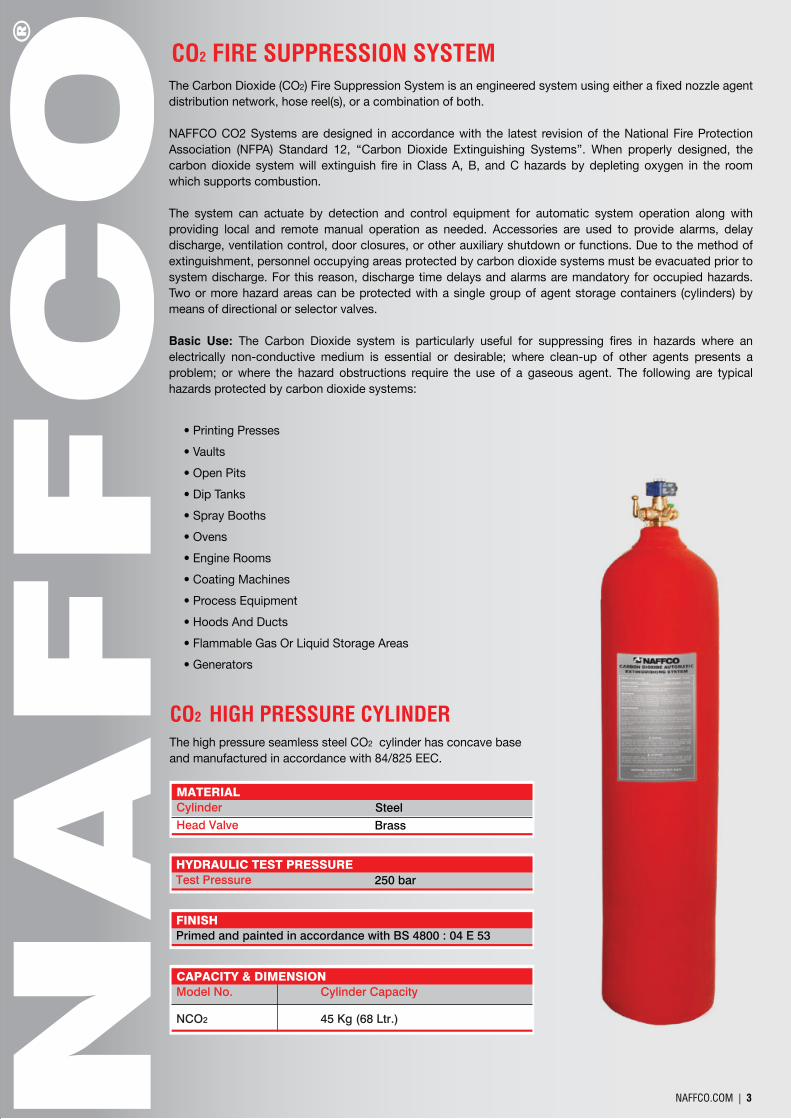
The Carbon Dioxide (CO2) Fire Suppression System is an engineered system using either a fixed nozzle agent distribution network, hose reel(s), or a combination of both.
NAFFCO CO2 Systems are designed in accordance with the latest revision of the National Fire Protection Association (NFPA) Standard 12, ‘‘Carbon Dioxide Extinguishing Systems’’. When properly designed, the carbon dioxide system will extinguish fire in Class A, B, and C hazards by depleting oxygen in the room which supports combustion.
The system can actuate by detection and control equipment for automatic system operation along with providing local and remote manual operation as needed. Accessories are used to provide alarms, delay discharge, ventilation control, door closures, or other auxiliary shutdown or functions. Due to the method of extinguishment, personnel occupying areas protected by carbon dioxide systems must be evacuated prior to system discharge. For this reason, discharge time delays and alarms are mandatory for occupied hazards. Two or more hazard areas can be protected with a single group of agent storage containers (cylinders) by means of directional or selector valves.
Basic Use: The Carbon Dioxide system is particularly useful for suppressing fires in hazards where an electrically non-conductive medium is essential or desirable; where clean-up of other agents presents a problem; or where the hazard obstructions require the use of a gaseous agent. The following are typical hazards protected by carbon dioxide systems:
CO2 FIRE SUPPRESSION SYSTEM
The high pressure seamless steel CO2 cylinder has concave base and manufactured in accordance with 84/825 EEC.
• Printing Presses
• Vaults
• Open Pits
• Dip Tanks
• Spray Booths
• Ovens
• Engine Rooms
• Coating Machines
• Process Equipment
• Hoods And Ducts
• Flammable Gas Or Liquid Storage Areas
• Generators
CO2 HIGH PRESSURE CYLINDER
MATERIALSteelBrass
CylinderHead Valve
HYDRAULIC TEST PRESSURE250 barTest Pressure
FINISHPrimed and painted in accordance with BS 4800 : 04 E 53
NAFFCO.COM | 3
CAPACITY & DIMENSIONModel No.
NCO2
Cylinder Capacity
45 Kg (68 Ltr.)
NAFFCO.COM 2
INTRODUCTIONNational Fire Fighting Manufacturing FZCO (NAFFCO) was established in 1991 and has grown to become the largest fire fighting equipment manufacturer in the Middle East and one of the top manufacturers worldwide. The company’s core business focuses on design, manufacture, supply, installation and after sales services with our highly trained and experienced technicians and engineers for fire fighting products ranging from basic fire extinguishers to highly sophisticated fire engines. The company provides total fire protection solutions to the most prestigious developments around the world, including residential buildings, commercial complexes, telecommunication centers, industrial installations, oil refineries and petrochemical plants and airport installations. With its presence in over 100 countries, NAFFCO headquarters is located in United Arab Emirates, where a wide range of innovative fire fighting equipment are manufactured with the company’s state-of-the-art technology. The company is renowned for providing superb quality and assuring the timely performance of its products at all times. With simple yet effective fire extinguishers of all sizes, custom made fire cabinets, heavy duty fire hoses, high capacity powerful pumps, mobile fire fighting systems, including CAFS systems, and highly advanced fire engines, NAFFCO dedicated itself to the science of fire fighting.
Moreover, NAFFCO has diversified from the passive fire protection arena and considerd as one of the top specialized manufacturer of the entaire range “Fire Fighting Products, Systems, Fire Detection and security systems”. NAFFCO’s ISO 9001 QUALITY MANAGEMENT SYSTEM is certified by UL DQS inc, LPCB and BV. This organization endeavors to continually and effectively improve the quality of our products which are certified by international bodies like UL, FM, LPCB, BSI, SAI Global and SABS in accordance with the international standards of NFPA. As recognition to the success of our business growth, we have been accredited thrice with the prestigious Mohammed Bin Rashid Al Maktoum Business Award, in the year 2005 for excellence in exports, in 2006 & 2010 for manufacturing excellence under the free zones category. Furthermore as a manufacturer of complete fire protection solution provider, NAFFCO has also been recognised by the Dubai Quality Appreciation Program 2008, which is a testimony to our commitment to quality and consistent focus on business excellence. Motivated by our slogan “Think Safety, Think NAFFCO!” we strive to be the global leader in providing comprehensive and reliable fire protection solutions to make the world a safer place to live in.
The Carbon Dioxide (CO2) Fire Suppression System is an engineered system using either a fixed nozzle agent distribution network, hose reel(s), or a combination of both.
NAFFCO CO2 Systems are designed in accordance with the latest revision of the National Fire Protection Association (NFPA) Standard 12, ‘‘Carbon Dioxide Extinguishing Systems’’. When properly designed, the carbon dioxide system will extinguish fire in Class A, B, and C hazards by depleting oxygen in the room which supports combustion.
The system can actuate by detection and control equipment for automatic system operation along with providing local and remote manual operation as needed. Accessories are used to provide alarms, delay discharge, ventilation control, door closures, or other auxiliary shutdown or functions. Due to the method of extinguishment, personnel occupying areas protected by carbon dioxide systems must be evacuated prior to system discharge. For this reason, discharge time delays and alarms are mandatory for occupied hazards. Two or more hazard areas can be protected with a single group of agent storage containers (cylinders) by means of directional or selector valves.
Basic Use: The Carbon Dioxide system is particularly useful for suppressing fires in hazards where an electrically non-conductive medium is essential or desirable; where clean-up of other agents presents a problem; or where the hazard obstructions require the use of a gaseous agent. The following are typical hazards protected by carbon dioxide systems:
CO2 FIRE SUPPRESSION SYSTEM
The high pressure seamless steel CO2 cylinder has concave base and manufactured in accordance with 84/825 EEC.
• Printing Presses
• Vaults
• Open Pits
• Dip Tanks
• Spray Booths
• Ovens
• Engine Rooms
• Coating Machines
• Process Equipment
• Hoods And Ducts
• Flammable Gas Or Liquid Storage Areas
• Generators
CO2 HIGH PRESSURE CYLINDER
MATERIALSteelBrass
CylinderHead Valve
HYDRAULIC TEST PRESSURE250 barTest Pressure
FINISHPrimed and painted in accordance with BS 4800 : 04 E 53
NAFFCO.COM | 3
CAPACITY & DIMENSIONModel No.
NCO2
Cylinder Capacity
45 Kg (68 Ltr.)

CO2 SOLENOID HEAD VALVE
The differential pressure discharge head valves are use to be install in CO2 Cylinders to facilitate the discharge flow and installing the actuation device. The valve can be operated by electric actuator, pneumatic actuator or pneumatic manual actuator. Actuation of the control head displace the valve piston and CO2 is allow to flow through the discharge port of the valve.
NAFFCO.COM | 4
ELECTRICAL REQUIREMENT24 VDC10 Watts
Operating VoltagePower Consumption
MATERIALBrass
25E EN 629-1
w21.8 x 1/14’ DIN 477
m10 x 0.75
To be specified
Valve Body
Inlet Connection
Outlet Connection
Dip Tube Connection
Bursting Disk
CO2 Head Valve with solenoid valve can be use as head of: • Master Cylinder Head Valve • Pilot Cylinder Head Valve
CO2 Head Valve can be actuated by two methods of operation: • Manual / Mechanical actuator • Electric solenoid actuator
MATERIALBrass
25E EN 629-1
w21.8 x 1/14’ DIN 477
m16 x 1
M42 x 1.5
To be specified
Valve Body
Inlet Connection
Outlet Connection
Dip Tube Connection
Release Device Connection
Bursting Disk
OPERATING PARAMETER250 Bar-20ºC - +60ºC12mm
Working PressureTemperature RatingSeat Orifice Size
RELEASE DEVICE20 Bar
10 Watts
10 Bar
24 VDC
1 Ampere
Manual/Pneumatic
Pneumatic
Pneumatic Double Piston
Pyrotechnic
Electromagnetic
CO2 DIFFERENTIAL PRESSURE HEAD VALVE
OPERATING PARAMETER250 Bar
-20ºC - +60ºC
12mm
45 kg/min
Total Discharge
Kv = 0.69Cv = 0.80
Working Pressure
Temperature Rating
Seat Orifice Size
CO2 Discharge Rate
Discharge Rate
OperationSPECIFICATIONS
Valve – Brass Pilot Port - Stainless Steel
100 to 110 psi (689 to 758 kpa)
Materials
Operating Pressure
The cylinder valve assembly is a forged “brass” body. When the actuation pressure reaches 100 to 110 psi (689 to 758kPa), the valve opens automatically. Exceeding 3000 psi (20,685kPa) pressure in the cylinder, a safety relief disc, inserted into all valves, will rupture and a pilot port will be utilized for two aims:
• Fill port for charging the cylinder • Actuator port for both the manual/mechanical and electrical release functions
To settle the valve, two plugs must be removed and either the 12VDC or 24VDC actuation kit must be installed. For marine applications, the local lever actuator assembly must be installed for converting slave configuration to a master valve.
Operation:By entering through the valve discharge port, CO2 pressure frompiping manifold send pressure to the top piston chamber. Then, the slave valve cylinder is actuated.
The greater surface area of the piston allows discharging CO2 through the discharge port into the piping system, since the pressure pushes the main seal downward.
The pilot port send CO2 pressure of the cylinder to the top pressure port and the master valve cylinder actuates.
Plug
Plug
Discharge Port
Marine Master Valve
PNUEMATICACTUATION TUBING
PNUEMATIC CONNECTION HOSE(TO NEXT MASTER CYLINDER)
CO2 Valve Section View
Top Pressure Port
Internal Pressure Port
Pilot Port
DischargePort
Safety Relief
Discharge Port
CYLINDER VALVE ASSEMBLY
NAFFCO.COM | 5
evlaVretsaMevlaVevalS

MASTER CYILINDER ACTUATION PACKAGEThe NAFFCO Carbon Dioxide Master Cylinder Valve can be actuated by two methods of operation:
• Manual / Mechanical actuator
• Electric solenoid actuator (12VDC or 24VDC)
The 12VDC and 24VDC Master Cylinder actuation packagecontain the following items:
• 12VDC or 24VDC electric solenoid
• Manual Actuator
• (2) Stainless Steel Flexible hoses
• Stainless Steel connector
• (2) ¼” (8mm) X 90 Brass elbows
• 14” (8mm) Brass tee
The 12VDC and 24VDC solenoids meet the requirements of N.E.C Class 1, Group C & D and Class II Group E, F & G applications. A manual actuator is provided for local “override” purposes. For manifold cylinder applications, the manual actuators can provide simultaneous discharge of the master cylinders by onnecting together. After Operation, the electric or manual actuator can be reset without tool. For service, maintenance and inspection purposes, the master actuation package can be removed from the valve / cylinder even when the cylinder is full.
DESCRIPTIONC85-113 12VDC Master Cylinder Actuation PackageC85-114 24VDC Master Cylinder Actuation PackageC85-115 12VDC Solenoid w/Pressure GaugeC85-123 24VDC Solenoid w/Pressure Gauge
Brass and Stainless Steel
0ºF to 130ºF (-18ºC to 54ºC)
U.L. Ex4447Factory MutualU.L.C. CEx 1312
Part Number
Materials
Temperature Range
Approvals
Ex-Proof Solenoid with Pressure Gauge
NAFFCO.COM | 6
CO2 MANUAL/PNEUMATIC RELEASE ACTUATOR
The pneumatic actuator has a piston and it connected to a pin at the top of pressure differential head valve. When pilot pressure is applied to the piston pressure press the pin pushing the head valve diaphragm, thereby causing cylinder head valve to open.
The CO2 manual/pneumatic release is device required for slave actuation. This is a dual-purpose device, can be used as mechanical manual actuation or thru pilot line. It has an actuation piston to upset the discharge head valve when pilot pressure is applied to a piston. With the pressure applied through the pilot connection or by pulling, the lever of the pneumatic manual actuator presses the pressure differential head valve piston, thereby opening the cylinder to discharge its content.
Drain Valve
MATERIALBrassM42 X 1.5G 1/8”
Valve BodyInlet ConnectionPneumatic Connection
CO2 PNEUMATIC RELEASE ACTUATOR
Drain Valve
OPERATING PARAMETER
Pmax = 340 Bar
Pmax = 250 Bar
Pmax = 150 Bar
Working Pressure
20 Bar for 300 Bar System
15 bar for CO and 200 Bar System
10 Bar for System²
Drain Valve
MATERIALBrassM42 X 1.5G 1/8”
Valve BodyInlet ConnectionPneumatic Connection
Drain Valve
OPERATING PARAMETER
Pmax = 340 Bar
Pmax = 250 Bar
Pmax = 150 Bar
Working Pressure
20 Bar for 300 Bar System
15 bar for CO and 200 Bar System
10 Bar for System²
NAFFCO.COM | 7
CO2 FLEXIBLE DISCHARGE HOSE
The flexible discharge hoses are made to convey the CO2 gas from the cylinder head valves to the main manifold for gas distribution to nozzle piping network. The Discharge Hoses are equipped with an internal check valves to prevent the back flow of CO2
gas from the manifold to other cylinders.
Drain Valve
MATERIALRubberSteel S 300 Cadmied
HoseCoupling
Drain Valve
DIMENSION21.7 x 1.81410 mm
ConnectionDiameter Nominal
Drain Valve
PRESSURE RATING240 Bar400 Bar960 Bar
Service PressureTest PressureBursting Pressure
CO2 FLEXIBLE PILOT HOSE
The pilot flexible hose is used to interconnect the ports of the pressure actuators. The CO2 gas pressure applied on the pressure actuators open the cylinder valve simulta- neously.
Drain Valve
PRESSURE RATING240 Bar400 Bar960 Bar
Service PressureTest PressureBursting Pressure
Drain Valve
MATERIALRubberSteel S 300 Cadmied
1/8” BSP
HoseCouplingConnection

CO2 DISCHARGE NOZZLENozzle is made of brass and available in ½”, ¾” and 1” sizes. Orifice design to particular requirement with computer aided calculation to assure the effectiveness of extinguishing agent and reliable system design. The nozzles can be located around the perimeter or in the center of the protected space. The nozzles are available for both 180º and 360º discharge pattern.
NAFFCO.COM | 8
NAFFCO CONTINUOUS GAS WEIGHING DEVICE
NAFFCO GAS WEIGHT MONITORING CONTROL PANEL
MODEL: SD-GAS-W1000
MODEL: SD-GAS-CP
NAFFCO gas weighing device is used in gas based fixed extinguishing systems to monitor the weight of extinguishing agent in the cylinder to meet the NFPA Standards
Naffco Gas Weighing Control Panel supervise and indicate the status of Continuous Gas Weighing Device, which are holding the gas cylinders used in gas based fire suppression / extinguishing system
• Standard length of hanger rod is used with ring for hanging the cylinder
• Low weight indication can be calibrated at the site, if required
• Device is powered directly by two wires from the Gas Weight Monitoring
Control Panel
• Plug in type simple connection form on device to another
• Each cylinder is required on device
• 24VDC signal supply is derived form weighing device. No current
consumption by gas weight monitor during normal conditions.
While low weight indication is ON, the maximum current
consumption will be 10mA
• LED indication for low weight of agent
• Cylinder ring to be standard thread of cylinder neck
• Non-standard threads, suitable ring will be provided upon request
• LED indication for low weight of agent
• Cylinder ring to be standard thread of cylinder neck
• Non-standard threads, suitable ring will be provided upon request
NAFFCO.COM | 9
GAS WEIGHT MONITORING SYSTEM
NAFFCO Continuous Gas Weight Monitoring System is used in gas based fixed Extinguishing Systems to monitor the weight of extinguishing agent in the cylinder to meet the NFPA Standards.
Once in 6 months, Loss in Weight of cylinder must be checked and when it is superior to 10%, refilling must be done, in accordance with NFPA-12. One gas weighing device is required for each cylinder. This cylinder will be fixed through gas weighing device in hanging conditions.
If the weight of gas drop to 5% or 10% (depends on type of gas system), the low weight is indicated by means of LED indication. After reception of low weight indication from cylinder bank, the Gas Weight Monitoring Control panel gives audio and visual indication.
For remote indication or other relevant signaling, 2 set of potential free NO and NC contacts are available.
• Input supply voltage in 24VDC/230VAC/110VAC/50Hz
• Operating Voltage 24VDC
• Lamp test, acknowledge and rest control switches
• System ON Green LED, Low Weight Orange LED, Open and Short Yellow LED
• Unbolt Fault Buzzer of continuous lane
• Two wire, wiring is provided only common low weight indication per zone(individual law weight indication is available on continuous gas weighing device)
• This is Single Zone Control Panel
NAFFCO.COM | 10 NAFFCO.COM | 11
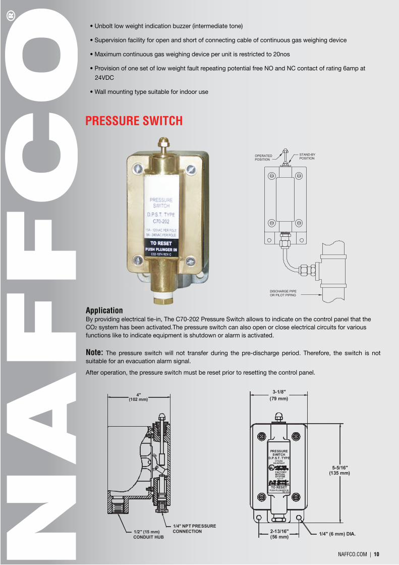
PRESSURE SWITCH
FACTORYMUTUALSYSTEM
C02-1074PUSH PLUNGER INTO RESET
A pproved
D.P.S.T. TYPERA INTIGHT
C70-202
SWITCHPRESSURE
3-1/8"(79 mm)
2-13/16"(56 mm) 1/4" (6 mm) DIA.
5-5/16"(135 mm)
OR PILOT PIPING
POSITIONSTAND-BY
POSITIONOPERATED
DISCHARGE PIPE
F
NO
1/4" NPT PRESSURECONNECTION1/2" (15 mm)
CONDUIT HUB
4"(102 mm)
ApplicationBy providing electrical tie-in, The C70-202 Pressure Switch allows to indicate on the control panel that the CO2 system has been activated.The pressure switch can also open or close electrical circuits for various functions like to indicate equipment is shutdown or alarm is activated.
Note: The pressure switch will not transfer during the pre-discharge period. Therefore, the switch is not suitable for an evacuation alarm signal. After operation, the pressure switch must be reset prior to resetting the control panel.
• Unbolt low weight indication buzzer (intermediate tone)
• Supervision facility for open and short of connecting cable of continuous gas weighing device
• Maximum continuous gas weighing device per unit is restricted to 20nos
• Provision of one set of low weight fault repeating potential free NO and NC contact of rating 6amp at
24VDC
• Wall mounting type suitable for indoor use
DIRECTIONAL VALVESMultiple hazards may be protected from a common supply of CO2 by using pneumatically operated directional valves. This is essentially an economy measure designed to reduce system size. It is also used only when it is certain that only one hazard could require a discharge at any time. It is operated pneumatically by gas pressure through cartridge system which can be actuated manually/electric actuator/solenoid valve.
Drain Valve
Model No: Test Pressure (bar) Size MaterialDV40A
DV50A
DV65ADV80ADV100A
DV125A
DV150A
250 bar
250 bar250 bar
250 bar
250 bar
250 bar
250 bar
40
5565
80
100
125
150
Bronze BC6
Bronze BC6
Bronze BC6
Bronze BC6Bronze BC6
Bronze BC6
Bronze BC6
The pressure switch is a double pole, single throw switch housed in a weather-proof back box. After the activation of system, the CO2 pressure from discharge piping operates the switch.
InstallationThe switch should be in the vertical position and mounted on a suitable surface. According to NFPA 12 requirements, it must use ¼” (8mm) piping to make the connection. Furthermore, it must use branch tees in the ¼” (8mm) piping for installation of additional pressure switches. Thus, the pressure switches are “daisy-chain” together.
FIRE ALARM DEVICESEXTINGUISHANT CONTROL PANELShield XT is a new generation extinguishant releasing panel which is fully compliant with European standard BS EN12094-1. (Fixed firefighting systems – components for gas extinguishing systems). The simple, programmable configuration options and easy to install construction make Shield XT panels the ideal choice for small to medium sized systems using all extinguishant agents.
Features
• Complies with EN12094-1
• Three detection zones as standard
• Any single zone or any combinations of zones can be configured to release
• Configurable first stage sounder delays
• Configurable detection delays
• Zero time delay upon manual release option
• Compatible with I.S. barriers
• Non-latching zone input option to receive signals from other systems such as aspirating equipment
• Configurable extinguishant delays up to 60 seconds in 5 second steps
• Configurable extinguishant duration up to 5 minutes in 5 second steps
• Countdown timer shows time remaining until release
• Supports up to seven, four wire status indicators
• Built in Extract Fan control

NAFFCO.COM | 10 NAFFCO.COM | 11
PRESSURE SWITCH
FACTORYMUTUALSYSTEM
C02-1074PUSH PLUNGER INTO RESET
A pproved
D.P.S.T. TYPERA INTIGHT
C70-202
SWITCHPRESSURE
3-1/8"(79 mm)
2-13/16"(56 mm) 1/4" (6 mm) DIA.
5-5/16"(135 mm)
OR PILOT PIPING
POSITIONSTAND-BY
POSITIONOPERATED
DISCHARGE PIPE
F
NO
1/4" NPT PRESSURECONNECTION1/2" (15 mm)
CONDUIT HUB
4"(102 mm)
ApplicationBy providing electrical tie-in, The C70-202 Pressure Switch allows to indicate on the control panel that the CO2 system has been activated.The pressure switch can also open or close electrical circuits for various functions like to indicate equipment is shutdown or alarm is activated.
Note: The pressure switch will not transfer during the pre-discharge period. Therefore, the switch is not suitable for an evacuation alarm signal. After operation, the pressure switch must be reset prior to resetting the control panel.
• Unbolt low weight indication buzzer (intermediate tone)
• Supervision facility for open and short of connecting cable of continuous gas weighing device
• Maximum continuous gas weighing device per unit is restricted to 20nos
• Provision of one set of low weight fault repeating potential free NO and NC contact of rating 6amp at
24VDC
• Wall mounting type suitable for indoor use
DIRECTIONAL VALVESMultiple hazards may be protected from a common supply of CO2 by using pneumatically operated directional valves. This is essentially an economy measure designed to reduce system size. It is also used only when it is certain that only one hazard could require a discharge at any time. It is operated pneumatically by gas pressure through cartridge system which can be actuated manually/electric actuator/solenoid valve.
Drain Valve
Model No: Test Pressure (bar) Size MaterialDV40A
DV50A
DV65ADV80ADV100A
DV125A
DV150A
250 bar
250 bar250 bar
250 bar
250 bar
250 bar
250 bar
40
5565
80
100
125
150
Bronze BC6
Bronze BC6
Bronze BC6
Bronze BC6Bronze BC6
Bronze BC6
Bronze BC6
The pressure switch is a double pole, single throw switch housed in a weather-proof back box. After the activation of system, the CO2 pressure from discharge piping operates the switch.
InstallationThe switch should be in the vertical position and mounted on a suitable surface. According to NFPA 12 requirements, it must use ¼” (8mm) piping to make the connection. Furthermore, it must use branch tees in the ¼” (8mm) piping for installation of additional pressure switches. Thus, the pressure switches are “daisy-chain” together.
FIRE ALARM DEVICESEXTINGUISHANT CONTROL PANELShield XT is a new generation extinguishant releasing panel which is fully compliant with European standard BS EN12094-1. (Fixed firefighting systems – components for gas extinguishing systems). The simple, programmable configuration options and easy to install construction make Shield XT panels the ideal choice for small to medium sized systems using all extinguishant agents.
Features
• Complies with EN12094-1
• Three detection zones as standard
• Any single zone or any combinations of zones can be configured to release
• Configurable first stage sounder delays
• Configurable detection delays
• Zero time delay upon manual release option
• Compatible with I.S. barriers
• Non-latching zone input option to receive signals from other systems such as aspirating equipment
• Configurable extinguishant delays up to 60 seconds in 5 second steps
• Configurable extinguishant duration up to 5 minutes in 5 second steps
• Countdown timer shows time remaining until release
• Supports up to seven, four wire status indicators
• Built in Extract Fan control

NAFFCO.COM | 12 NAFFCO.COM | 13
CONVENTIONAL PHOTOELECTRIC SMOKE DETECTOR
CONVENTIONAL RATE OF RISE AND FIXED TEMPERATURE HEAT DETECTOR
Features
• Twin LED for 360° view.
• Remote indicator output available.
• Complies with EN 54-7 standard.
Features
• Twin LED for 360° view.
• Built-in microprocessor samples and collects data in real time.
• Rate of rise and fixed temperature alarm modes
• Remote indicator output available.
• Complies with EN 54-5 standard.
D-C401 Conventional Photoelectric Smoke Detector is non- addressable. Used together with end of line unit, it can connect with compatible control panels to process detection signals. It shows fire alarm by LED indicators and transmits the fire signal to the control panel. Using infrared scattering technology, the smoke density can be detected. The detector receives very weak infrared light under normal smokeless condition. If smoke particles enter the chamber, the received light signal will increase by scattering. When smoke density reaches a pre-set level, the detector will alarm out. In order to reduce interference and power consumption, the emitting circuit works in pulse mode to prolong the life of IR LED.
D-C402 Conventional Rate of Rise and Fixed Temperature Heat Detector is non-addressable. With built-in microprocessor, it works stably with reliable fixed fire judging program. Used together with an active end of line unit (AEOL), it can connect with compatible control panels to process fire alarm signals. It transmits fire signal to fire alarm control panel or interface module by changing its own current and shows the fire alarm by LED indicator until it’s reset.
CONVENTIONAL SOUNDER STROBE
Features
• High bright red LEDs are used as light source.
• High sound level, over 75dB at 3m ahead horizontally (A weighted).
• Circuitry and base are twisted together.
• Standard: EN 54-3.
S-C481 Conventional Sounder Strobe is a kind of audible and visual alarm device used to warn people in field when fire occurs. It can give audible and visual alarm when applied to 24VDC power (D1 connected with anode and D2 with cathode). To connect it with fire alarm control panel, an addressable control module should be added to the system, such as AI-510 Addressable Single I/O Module. Both shallow base with 25.5mm high and deep base with 40mm high are available, deep base is used if there is no special statement in this manual.
FIRE ALARM BELL
Features
• Low current consumption - only 20mA
• Quickly and easily installed
• Excellent sound, up to 100dBA @ 1mt.
• Suitable for indoor and outdoor use
• Easy installation and connection.
• Operating Voltage: - 6VDC, 12VDC, 24V DC - 120VAC, 220VAC
The FB-1000 series Bells are of aluminum construction and have a very high sound output matched with extremely low power consumption with 20mA for the 6” alarm bell. The FB-1000 series can be used for internal and external installation using the specially designed weatherproof bells having an aluminum back box giving either single or double threaded entry for maximum flexibility in installation. Weatherproof bells are supplied as a full fixing kit with gasket and screws.
Nominal Voltage : 24VDC
Current : 40mA
Colour : Red
Flash Frequency : 1Hz
Flash Energy : 0.7j
Weight : 300 grams
XENON BEACON
MODEL: XB1000 SERIES
ABORT SWITCH
MODEL: AS500 SERIES
Supply Voltage : 24VDC
Electrical Monitoring : 470R series resistor
Operating Temperature : -20°C to + 80°C
Colour : Blue with transparent colour (Optional)
Supply Voltage : 24VDC
Electrical Monitoring : 470R series resistor
Operating Temperature : -20°C to + 80°C
Colour : Yellow with transparent colour (Optional)
MANUAL RELEASE STATION
MODEL: RS1000 SERIES

THE FIRE PROTECTION SPECIALISTS
National Fire Fighting Manufacturing FZCO
PO Box 17014, Dubai, United Arab Emirates, Tel 971 4 806 6666, Fax 971 4 881 6229Email: [email protected], www.naffco.com
We reserve the right to modify specifications without prior notice
Our Aim is to become your supplier of choice while focusingon value added products and services that matter most to you
QUALITY SYSTEM National Fire Fighting Manufacturing FZCO is certified to ISO 9001 Quality system by Underwriters Laboratories Inc, Loss Prevention Certification Board UK & Bureau Veritas. Our manufacturing processes are based on a quality system that ensures the use of raw material confirming to relevant International Standards. Our In process production is monitored by work standards & quality plans confirming to relevant International
standards enabling us to deliver quality products.
APPROVALSNAFFCO has successfully achieved ISO 9001 Quality Management system certified by UL, LPCB & BV. Further we have achieved Product certification from UL, FM, LPCB, BSI, CE & SAI Global on wide range of products which include Fire Extinguishers, Fire Hose Reels, Centrifugal Fire Pumps, Diesel Engine for driving Fire
pumps, Fire doors, Fire Fighting equipment & Certification for Fire Alarm systems installations.
ENGINEERING CAPABILITIESNAFFCO is backed by a team of professionals who are well qualified and specialized in their respective field viz - Design, Development, Production and Project Implementation. Our investment in applied research and
development program concentrates on innovations which meets customer needs.
PRODUCT RANGE
1
PRODUCTCERTIFICATION