
Otter Pro XT Lodge
13
Page 1 Otter Pro XT Lodge Installation and Set-Up Instructions Otter Pro XT Lodge Fits Magnum Otter II & Pro Sled Only Parts Identification and Check List PAR AR AR AR ARTS LIST TS LIST TS LIST TS LIST TS LIST Item # Item # Item # Item # Item # Qty Qty Qty Qty Qty Part # Part # Part # Part # Part # Description Description Description Description Description 1 1 201067 Sled - Dark Gray 2 1 200967 Tent - XT Thermal Lodge 3 1 80172 Frame Bracket “A” 4 1 80171 Frame Bracket “B” 5 1 80517 Back Wind Support Bar - 49 1/2” 6 1 80518 Center Wind Support Bar - 34 5/8” 7 1 80519 Center Wind Support Bar - 44 3/4” 8 1 80512 Adjustable Front Wind Support Bar 9 2 80470 Main Frame Extension Bar - 31 1/2” 10 2 80471 Main Frame Extension Bar - 32 1/2” 11 4 80472 Main Frame Extension Bar - 30” 12 2 80474 Outer Main Frame Bar - 33” 13 6 80473 Outer Main Frame Bar - 29 9/16” 14 4 80475 Middle Main Frame Bar - 52” 15 2 200861 Seat 16 2 200369 Seat Bracket 17 2 200806 Seat Base 18 1 200379 Seat Rail - 67” 19 2 200196 Seat Rail Cap 20 2 200376 Seat Rail Bracket 21 8 200384 Sleeve 22 16 400641 #8 x 3/4” Self Tapping Screw 23 8 200197 Black Plug 24 8 200195 Black End Cap 25 14 200615 5/16 Washer 26 8 200944 1/4 x 1/2 Philips Head, Counter Sunk Screw 27 4 401017 1/4 x 3/4 Hex Bolt 28 16 400648 1/4 Nylon Hex Lock Nut 29 2 400367 5/16 x 2 Hex Bolt 30 2 200787 5/16 Nylon Hex Lock Nut 31 8 200235 1/4” Low Profile Nylon Lock Nut 32 12 200942 3/8” Self Tapping Screw 33 16 200941 Plastic Protector 34 16 200943 Star Washer 35 1 200976 Plastic Trim Lock Kit MODEL NUMBERS: MODEL NUMBERS: MODEL NUMBERS: MODEL NUMBERS: MODEL NUMBERS: Complete Pkg Complete Pkg Complete Pkg Complete Pkg Complete Pkg Pro XT Thermal Lodge Pro XT Thermal Lodge Pro XT Thermal Lodge Pro XT Thermal Lodge Pro XT Thermal Lodge 200958 200958 200958 200958 200958 2 1 5 6 7 8 3 11 10 9 13 12 14 4 16 17 15 Front Back Center Bottom Back & Center Front Bottom All 23 22 21 19 18 20 Instructions - 70761 24 25 28 27 26 30 29 31 32 33 34 35
Transcript of Otter Pro XT Lodge
Page 1
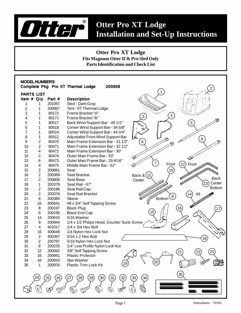
Otter Pro XT LodgeInstallation and Set-Up Instructions
Otter Pro XT LodgeFits Magnum Otter II & Pro Sled Only
Parts Identification and Check List
PPPPPARARARARARTS LISTTS LISTTS LISTTS LISTTS LISTItem #Item #Item #Item #Item # QtyQtyQtyQtyQty Part #Part #Part #Part #Part # DescriptionDescriptionDescriptionDescriptionDescription
1 1 201067 Sled - Dark Gray2 1 200967 Tent - XT Thermal Lodge3 1 80172 Frame Bracket “A”4 1 80171 Frame Bracket “B”5 1 80517 Back Wind Support Bar - 49 1/2”6 1 80518 Center Wind Support Bar - 34 5/8”7 1 80519 Center Wind Support Bar - 44 3/4”8 1 80512 Adjustable Front Wind Support Bar9 2 80470 Main Frame Extension Bar - 31 1/2”10 2 80471 Main Frame Extension Bar - 32 1/2”11 4 80472 Main Frame Extension Bar - 30”12 2 80474 Outer Main Frame Bar - 33”13 6 80473 Outer Main Frame Bar - 29 9/16”14 4 80475 Middle Main Frame Bar - 52”15 2 200861 Seat16 2 200369 Seat Bracket17 2 200806 Seat Base18 1 200379 Seat Rail - 67”19 2 200196 Seat Rail Cap20 2 200376 Seat Rail Bracket21 8 200384 Sleeve22 16 400641 #8 x 3/4” Self Tapping Screw23 8 200197 Black Plug24 8 200195 Black End Cap25 14 200615 5/16 Washer26 8 200944 1/4 x 1/2 Philips Head, Counter Sunk Screw27 4 401017 1/4 x 3/4 Hex Bolt28 16 400648 1/4 Nylon Hex Lock Nut29 2 400367 5/16 x 2 Hex Bolt30 2 200787 5/16 Nylon Hex Lock Nut31 8 200235 1/4” Low Profile Nylon Lock Nut32 12 200942 3/8” Self Tapping Screw33 16 200941 Plastic Protector34 16 200943 Star Washer35 1 200976 Plastic Trim Lock Kit
MODEL NUMBERS:MODEL NUMBERS:MODEL NUMBERS:MODEL NUMBERS:MODEL NUMBERS:Complete PkgComplete PkgComplete PkgComplete PkgComplete Pkg Pro XT Thermal LodgePro XT Thermal LodgePro XT Thermal LodgePro XT Thermal LodgePro XT Thermal Lodge 200958200958200958200958200958 2
1
5
6
7
8
3
1110
9
13
12
14
4
16 1715
Front
BackCenterBottom
Back &Center
Front
BottomAll
232221
19
18
20
Instructions - 70761
24 25 282726 3029 31 32 33 3435
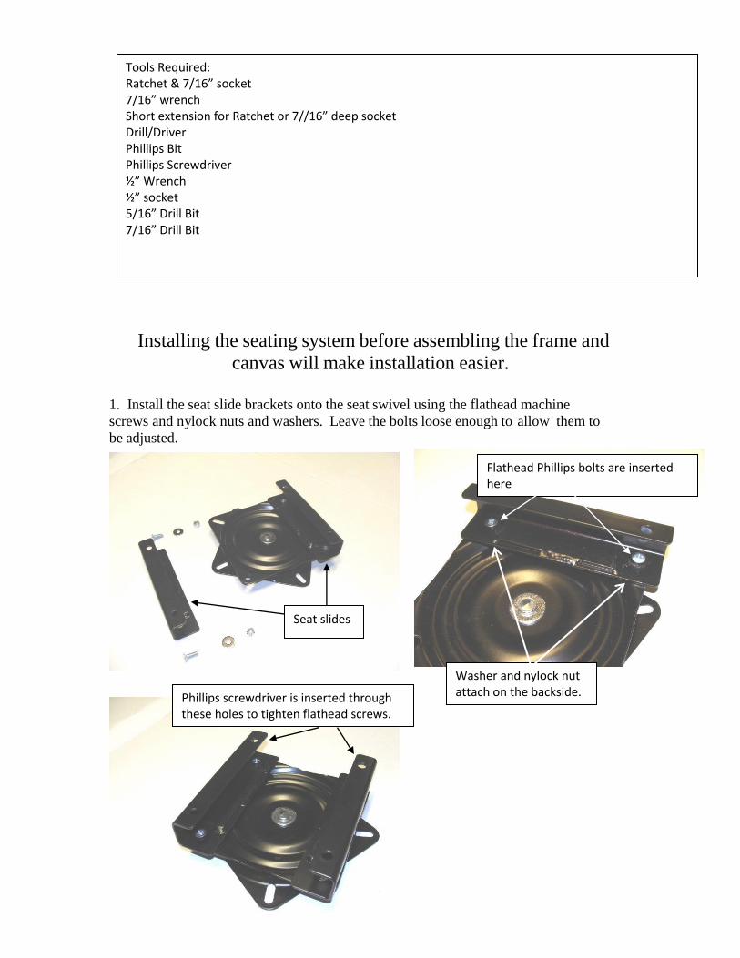
Installing the seating system before assembling the frame and
canvas will make installation easier.
1. Install the seat slide brackets onto the seat swivel using the flathead machine
screws and nylock nuts and washers. Leave the bolts loose enough to allow them to
be adjusted.
Tools Required: Ratchet & 7/16” socket 7/16” wrench Short extension for Ratchet or 7//16” deep socket Drill/Driver Phillips Bit Phillips Screwdriver ½” Wrench ½” socket 5/16” Drill Bit 7/16” Drill Bit
Seat slides
Flathead Phillips bolts are inserted here
Phillips screwdriver is inserted through these holes to tighten flathead screws.
Washer and nylock nut attach on the backside.
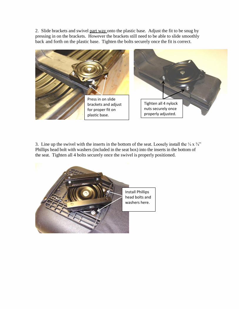
2. Slide brackets and swivel part way onto the plastic base. Adjust the fit to be snug by
pressing in on the brackets. However the brackets still need to be able to slide smoothly
back and forth on the plastic base. Tighten the bolts securely once the fit is correct.
3. Line up the swivel with the inserts in the bottom of the seat. Loosely install the ¼ x ¾”
Phillips head bolt with washers (included in the seat box) into the inserts in the bottom of
the seat. Tighten all 4 bolts securely once the swivel is properly positioned.
Press in on slide brackets and adjust for proper fit on plastic base.
Tighten all 4 nylock nuts securely once properly adjusted.
Install Phillips head bolts and washers here.
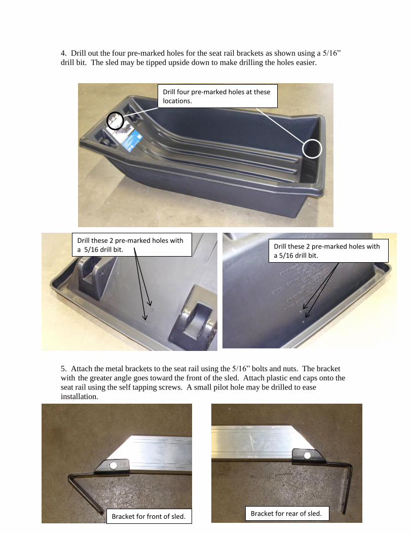
4. Drill out the four pre-marked holes for the seat rail brackets as shown using a 5/16”
drill bit. The sled may be tipped upside down to make drilling the holes easier.
5. Attach the metal brackets to the seat rail using the 5/16” bolts and nuts. The bracket
with the greater angle goes toward the front of the sled. Attach plastic end caps onto the
seat rail using the self tapping screws. A small pilot hole may be drilled to ease
installation.
Drill four pre-marked holes at these locations.
Drill these 2 pre-marked holes with a 5/16 drill bit. Drill these 2 pre-marked holes with
a 5/16 drill bit.
Bracket for front of sled. Bracket for rear of sled.

6. After the brackets and end caps are installed the seat rail may be bolted into place
with the ¼” bolts, washers and nylock nuts using the previously drilled holes.
Install plastic base and seat onto the rail. Use WD-40 or silicone to lubricate plastic
seat base opening so it will go onto the aluminum rail easier.
Install plastic end caps here.
Secure with ¾” self tapping screws.
Install seat rail here. Some downward pressure may be necessary to get the holes to align.
Bolt rear bracket to sled here.
Bolt front bracket to sled here.
Lubricate here for easier pivoting on the seat rail.
Two seat bases and one seat installed.

Page 5
Diagram 8
Item 25 - 5/16 WasherItem 28 - 1/4 Nylon Hex Lock Nut
10. Bolt frame brackets (Item 3 and Item 4) to sled using holes predrilled in Step 8.Use appropriate fasteners shown in Diagram 8.
3
25
28
4
7. Position sled (Item 1) as shown in Diagram 7 with curved front to your left.8. Drill the 4 marked holes using a 5/16” bit.9. Drill the 7/16” hole in center of lip approximately 16” from bend in sled. The back wind support bar (Item 5 not
shown) is to be propped here. Ref Diagram 7.
Diagram 7
Drill 4 premarked holeswith 5/16” drill bit.
16”
7/16”Hole
1
Seat assembly not shown for clarity.
Page 6
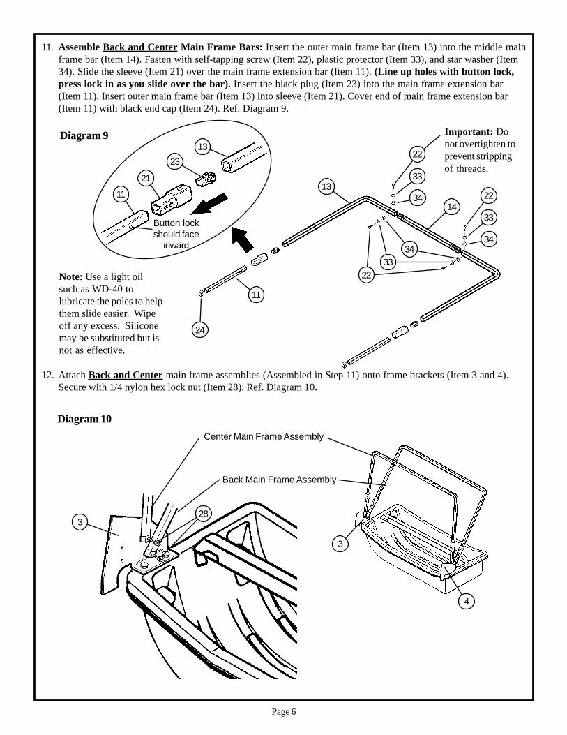
12. Attach Back and Center main frame assemblies (Assembled in Step 11) onto frame brackets (Item 3 and 4).Secure with 1/4 nylon hex lock nut (Item 28). Ref. Diagram 10.
4
3
3
Back Main Frame Assembly
Center Main Frame Assembly
28
Diagram 10
11. Assemble Back and Center Main Frame Bars: Insert the outer main frame bar (Item 13) into the middle mainframe bar (Item 14). Fasten with self-tapping screw (Item 22), plastic protector (Item 33), and star washer (Item34). Slide the sleeve (Item 21) over the main frame extension bar (Item 11). (Line up holes with button lock,press lock in as you slide over the bar). Insert the black plug (Item 23) into the main frame extension bar(Item 11). Insert outer main frame bar (Item 13) into sleeve (Item 21). Cover end of main frame extension bar(Item 11) with black end cap (Item 24). Ref. Diagram 9.
Diagram 9
2313
21
24
Button lockshould face
inward
1113
11
Note: Use a light oilsuch as WD-40 tolubricate the poles to helpthem slide easier. Wipeoff any excess. Siliconemay be substituted but isnot as effective.
14
33
34
33
34
22
3334
22
Important: Donot overtighten toprevent strippingof threads.
22

Page 7
14. Attach Front main frame assembly (Assembled in Step 13) onto frame brackets (Item 3 and 4). Secure with 1/4nylon hex lock nut (Item 28). Ref. Diagram 12
4
3
3
Front Main Frame Assembly
Diagram 12
28
13. Assemble Front Main Frame Bar: Insert the outer main frame bar (Item 12) into the middle main frame bar(Item 14). Fasten with self-tapping screw (Item 22), plastic protector (Item 33), and star washer (Item 34). Slidethe sleeve (Item 21) over the main frame extension bar (Item 10). (Line up holes with button lock, press lockin as you slide over the bar). Insert the black plug (Item 23) into the main frame extension bar (Item 10). Insertouter main frame bar (Item 12) into sleeve (Item 21). Cover end of main frame extension bar (Item 10) with blackend cap (Item 24). Ref. Diagram 11.
Diagram 11
Note: Use a light oilsuch as WD-40 tolubricate the poles to helpthem slide easier. Wipeoff any excess. Siliconemay be substituted but isnot as effective.
2312
21
24
Button lockshould face
inward
1012
10
14
33
34
33
34
22
3334
22
Important: Donot overtighten toprevent strippingof threads.
22
Page 8
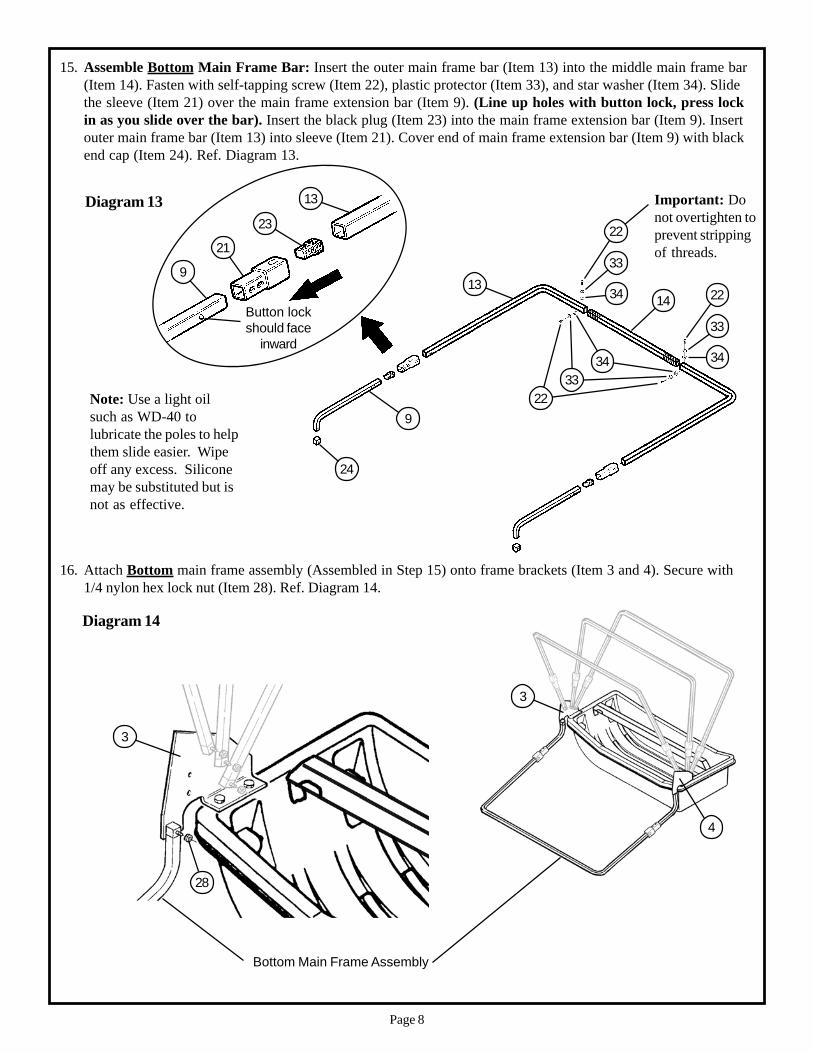
16. Attach Bottom main frame assembly (Assembled in Step 15) onto frame brackets (Item 3 and 4). Secure with1/4 nylon hex lock nut (Item 28). Ref. Diagram 14.
4
3
3
Diagram 14
28
Bottom Main Frame Assembly
23
21
Button lockshould face
inward
15. Assemble Bottom Main Frame Bar: Insert the outer main frame bar (Item 13) into the middle main frame bar(Item 14). Fasten with self-tapping screw (Item 22), plastic protector (Item 33), and star washer (Item 34). Slidethe sleeve (Item 21) over the main frame extension bar (Item 9). (Line up holes with button lock, press lockin as you slide over the bar). Insert the black plug (Item 23) into the main frame extension bar (Item 9). Insertouter main frame bar (Item 13) into sleeve (Item 21). Cover end of main frame extension bar (Item 9) with blackend cap (Item 24). Ref. Diagram 13.
Diagram 13
24
9
13
9
13
Note: Use a light oilsuch as WD-40 tolubricate the poles to helpthem slide easier. Wipeoff any excess. Siliconemay be substituted but isnot as effective.
14
33
34
33
34
22
3334
22
Important: Donot overtighten toprevent strippingof threads.
22
Page 9
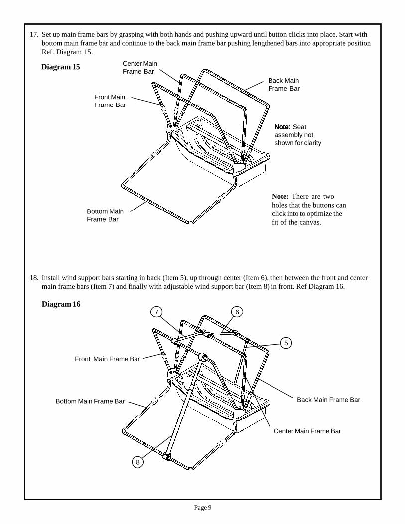
18. Install wind support bars starting in back (Item 5), up through center (Item 6), then between the front and centermain frame bars (Item 7) and finally with adjustable wind support bar (Item 8) in front. Ref Diagram 16.
Diagram 16
Bottom Main Frame Bar
Front Main Frame Bar
Center Main Frame Bar
Back Main Frame Bar
5
67
8
17. Set up main frame bars by grasping with both hands and pushing upward until button clicks into place. Start withbottom main frame bar and continue to the back main frame bar pushing lengthened bars into appropriate positionRef. Diagram 15.
Diagram 15
Bottom MainFrame Bar
Front MainFrame Bar
Center MainFrame Bar
Back MainFrame Bar
Note:Note:Note:Note:Note: Seatassembly notshown for clarity
Note: There are twoholes that the buttons canclick into to optimize thefit of the canvas.
Page 10
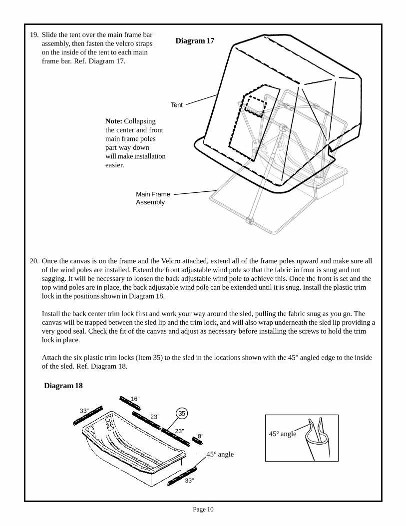
19. Slide the tent over the main frame barassembly, then fasten the velcro strapson the inside of the tent to each mainframe bar. Ref. Diagram 17.
Tent
Main FrameAssembly
Diagram 17
Note: Collapsingthe center and frontmain frame polespart way downwill make installationeasier.
45° angle
35
45° angle
8”
33”
23”
16”
33”
23”
20. Once the canvas is on the frame and the Velcro attached, extend all of the frame poles upward and make sure allof the wind poles are installed. Extend the front adjustable wind pole so that the fabric in front is snug and notsagging. It will be necessary to loosen the back adjustable wind pole to achieve this. Once the front is set and thetop wind poles are in place, the back adjustable wind pole can be extended until it is snug. Install the plastic trimlock in the positions shown in Diagram 18.
Install the back center trim lock first and work your way around the sled, pulling the fabric snug as you go. Thecanvas will be trapped between the sled lip and the trim lock, and will also wrap underneath the sled lip providing avery good seal. Check the fit of the canvas and adjust as necessary before installing the screws to hold the trimlock in place.
Attach the six plastic trim locks (Item 35) to the sled in the locations shown with the 45° angled edge to the insideof the sled. Ref. Diagram 18.
Diagram 18
Page 11
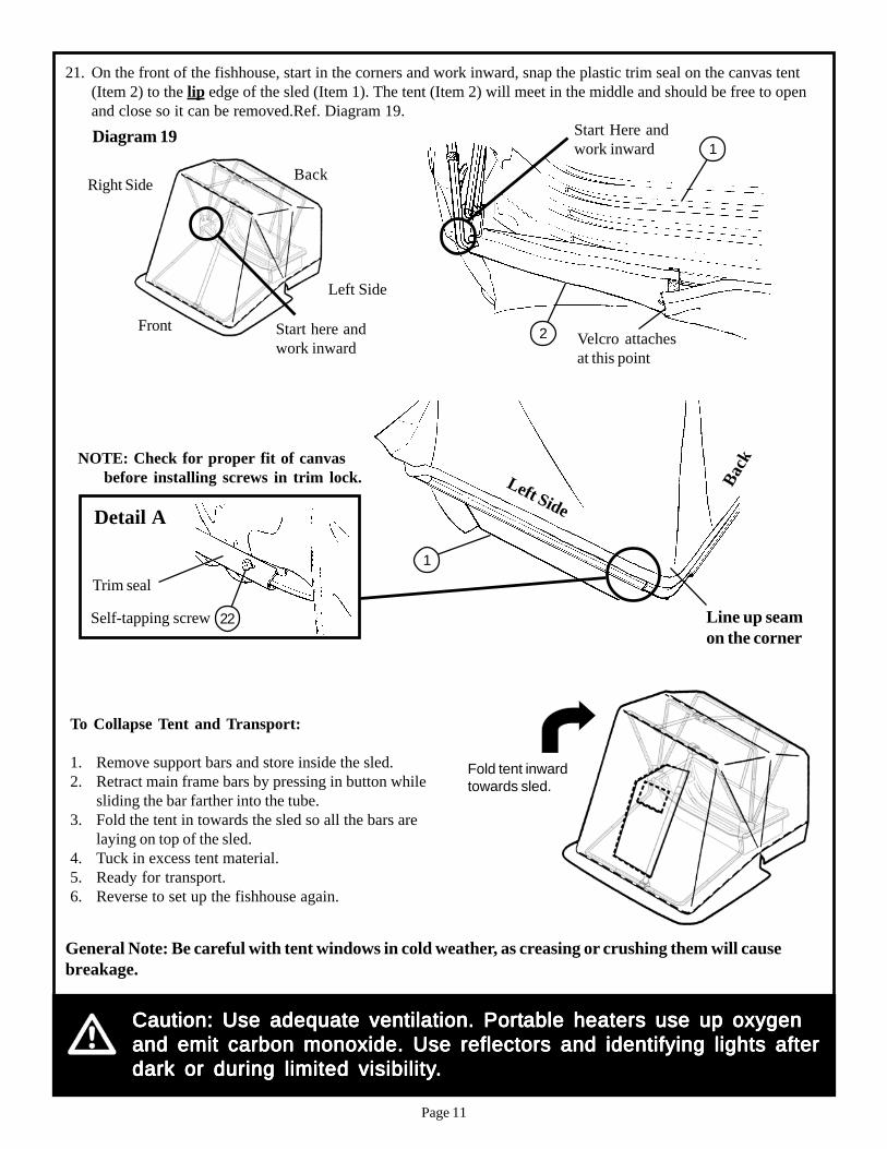
General Note: Be careful with tent windows in cold weather, as creasing or crushing them will causebreakage.
Caution: Use adequate ventilation. PortCaution: Use adequate ventilation. PortCaution: Use adequate ventilation. PortCaution: Use adequate ventilation. PortCaution: Use adequate ventilation. Portable heaters use up oxygenable heaters use up oxygenable heaters use up oxygenable heaters use up oxygenable heaters use up oxygenand emit carbon monoxide. Use reflectors and identifying lights afterand emit carbon monoxide. Use reflectors and identifying lights afterand emit carbon monoxide. Use reflectors and identifying lights afterand emit carbon monoxide. Use reflectors and identifying lights afterand emit carbon monoxide. Use reflectors and identifying lights afterdark or during limited visibilitydark or during limited visibilitydark or during limited visibilitydark or during limited visibilitydark or during limited visibility.....
To Collapse Tent and Transport:
1. Remove support bars and store inside the sled.2. Retract main frame bars by pressing in button while
sliding the bar farther into the tube.3. Fold the tent in towards the sled so all the bars are
laying on top of the sled.4. Tuck in excess tent material.5. Ready for transport.6. Reverse to set up the fishhouse again.
Fold tent inwardtowards sled.
21. On the front of the fishhouse, start in the corners and work inward, snap the plastic trim seal on the canvas tent(Item 2) to the lip edge of the sled (Item 1). The tent (Item 2) will meet in the middle and should be free to openand close so it can be removed.Ref. Diagram 19.Diagram 19
Start here andwork inward
Back
Left Side
Front
Right Side
Start Here andwork inward
2
1
Velcro attachesat this point
Trim seal
Self-tapping screw
Detail A
22
Left Side
Back
1
Line up seamon the corner
NOTE: Check for proper fit of canvasbefore installing screws in trim lock.
Page 12
Otter Pro XT LodgeOctober, 2015
Otter Outdoors Inc.411 W Congress St. • Maple Lake, MN 55358Phone 320-963-6480 • www.otteroutdoors.com