OTTAWA , 'I~' OTTAWA .' APR - McMaster University · PDF fileOTTAWA .' i . APR.3 0 1974 NAME...
153
.. ZU;;J5 NATIONAL LIBRARY . 'OTTAWA ) • ••• ," . BIBLIOTHEQUE NATIONALE OTTAWA .' i . APR.3 0 1974 NAME OF AImIOR: .... .. .. .............. .. TITLE OF niESIS •... .. ........ , ................................... . . . . . . . . . . .. . . . . . . . . . . . . . . . . . . . . . . . . . . . . . . . . . . . University·' . UN IVERS ITY •••••••••••••••••••••••••••••••••••••••••.••..•••• DEGREE FOR wHICH niESIS WAS PRESENTED. .............. . . 197. YEAR nirs DEGREE GRANTED.; .............. ; .................. . Permission is hereby granted to THE }NATIONAL LIBRARY OF CANADA to microfilm this tPesis and to lend or sell copies of the film: The author reserves other publication rights, and neither the nor extensive extracts from it may be printed reproduced without the author'S written permission. (51",.". .... PERMANENT ADDRESS: . -- ., ... . .. . J.it .r.kS\ . V C\i.'(: ..••.. . . . Y\ ............ . DATED .... .1 .. ........ 19 74 f , . NL-91nO-Ml .,
Transcript of OTTAWA , 'I~' OTTAWA .' APR - McMaster University · PDF fileOTTAWA .' i . APR.3 0 1974 NAME...

~ .. ZU;;J5
NATIONAL LIBRARY . 'OTTAWA ) •
•••
," 'I~' .
BIBLIOTHEQUE NATIONALE OTTAWA
.'
i . APR.3 0 1974
NAME OF AImIOR: .... ~~.a.~:n .. ~~~.~.· .. ~~.L.~~~ .............. .. TITLE OF niESIS •... ~~.s.~ ~~ .. O.~. ~~.i.~~?:.C.~~. ~.O.~~~~.t.~. ~~.l.~mns
........ , ................................... . .
. . . . . . . . . . . . . . . . . . . . . . . . . . . . . . . . . . . . . . . . . . . . . Pc~aster University·' . UN IVERS ITY •••••••••••••••••••••••••••••••••••••••••.••..••••
DEGREE FOR wHICH niESIS WAS PRESENTED. ~:X~?:· .............. . . 197.
YEAR nirs DEGREE GRANTED.; .............. ; .................. .
Permission is hereby granted to THE }NATIONAL LIBRARY
OF CANADA to microfilm this tPesis and to lend or sell copies
of the film:
The author reserves other publication rights, and
neither the ~hesis nor extensive extracts from it may be
printed or.~therwiso reproduced without the author'S
written permission.
(51",.". .... ~'. PERMANENT ADDRESS: .
--., ...
. Cyjl··~··~<:ft:···· ..
. J.it .r.kS\ ~v. . V C\i.'(: ..••..
. . . ~N"Y\;.\±Q Y\ ............ .
DATED .... A.~~~ .1 .. ~? ........ 19 74 f
, .
NL-91nO-Ml
.,

.,. .'
, I..
, "
DESIGN OF REINFORCED CONCRETe COLUMNS r
".
/
\
•
J
• ~ . I
,ltbblWlJ,£itGItJ,J_'lIJn. kiZAili.i-H .l.t •.. 1.(11.1$5 •.•. & ~1'

•
., •
.. \ •
( I
'DESIGN OF REINF0RCED CONCRETE COLUMNS
f
. , by
SAAD E.A. SAL LAM , R.Sc. ,
A. Thesis • •
'Submitted to ·the Faculty of Graduate Studies /
in Partial FU~£il;me~t of tpe Requirements •
for'the Degree.' '
.Master of Engineering
,
. , ~IC/Olaster University
Hamilton, Ontario \
Canada
1974 ' 1-----~----~----------
® Saaq E.A. Sallam 1974
. ' .. ,,. iSM:

, , ,
. \
\
..
.' I ,
To My Dea;r Wife SANAA
whose "
. . G
Patience, Understanding" and Assistance \
are deeply appreciated.
,
)
ii
•
I
..

(1)
"
, .
' ..• I
ACKNOWLEDGEMENTS
The a.uthor wisHes' to ~xpress. his' sinc,ere gratitude to Dr. R.G',
Drysdale fo~'his,guidance and intorest during the course of th~s~tudy•. ,
It h.as ~een a privilege and (pleasure to work under his supervision,.
The.valu~ble suggestions from members,of the faculty and from friends
are gratefully acknOWledged., I
The author also takes this'opport~ity~othanktho following~
McMaster -University.for providing financiat support 'in theif '.'
form of teaching ~~istnt1t~hip and scnolarsh.ip, and the
National Resca~ch Council of ~anada for additional support.
(2) Dr. J.J. Emery for'1ending'his comp~ct subroutines whi~h
hel~ed to overcome comp4ter programming difficulties:
;' y
"
-'',1, t'
'.
,,.
"
','\,
,1
iii:

-, J.
'.
MASTER OF ENGINEERING (1974)
, McMaster University
,Hamilton, Ontario;
CANADA
, .
TITLE: DESIGN OF REINFORCED CONCRETE COLUMNS
AUTHOR: Saad El.Din Abdalla SALLAM, B.Sc. (Cairo University)
SUPERVISOR: Dr. R.G.·Drysdalo
NUMBER OF PAGES: 1 4 0
''f~!\••,\. :>);;..·\...:,.i.~.•.. " j'" . c r
!'- 'j. I
The design of column cross sections for known axial 'loads andy' .
momen~s has ,reached the stage where practical methods .give results which
SCOPE AND CONTENTS: .
. ,
agree very closelyiwith tests and with accurate analyses. However con
siderable uncertainty exists with r~gard to methods employed to take into1 '
account the effects of the additional moments causqd by deflection of
columns. Theoretical calculations can be used to accurately predict the'I, ,..
loads at which material failure or column instability will occur. How-
ever designers require simpler techniques which are sUfficierit~y general
in nature to be equally applicable to the· large variety of design c~es.
The effect of column slenderness which'is further co~licated by
consideration of creep under sustained load is the main topic of this, .
study. ,It is suggested that a.realistfc appraisal of design methods
must be based on the idea of consistent safety factors. Thus slender'\
columns subjected to s~tai?ed load must retain. sufficient reserve
capacit~ so that failure loads when compared to design loads provide.
,.-,IV

i· , I
, ."
, .equal safety factors. Tho·National Building Codo o~,C~nada is boing
rcvis~d to i~cludo tho relo~ant pr~visions of tho ACI S~andard 318-71(2).
Tho columnsana1ysed in this study wore designed in accordance with ACI!
Standard 318-71. Comprehonsive eva~uation of the design parameters ~~•
.the ACI method is giv9n in this thesis along with conclusions and comments •.It was observed that the ACI method does not yield consistent safety,factors for the different values of the deS:rgn parameters. The analyses"
"
and conclusions-of this study are given in details in chapters (6)
(7) .
,
, ~
v
/I,
",

"1,(
.~
TABLE OF CONTENTS
CHAPTER I: I[rR0DUCTION
do 1.1\ Goneral 11.2 New Design Mothods 31.3 Primary Factor~Affecting the Strength of a I'
Slender Column 6~ 1.4 Aim and Procedure
'J
7
CHAPTER II: LITERATURE REVIEW .
2.1 Literature Revie~~j
·82.2 Review of Slender Column Procedures 82.3 Historieal Review of the Determination of
Basic Strength of Slendcr~olumns 122.4 Review of Studies of Inel stic Behaviour r,of Concrete Structures 132.5 Work ln McMaster University 17 '.~ ,
2.6 St1IIIIIlollry 18
{
~..
.~
CHAPTER III: DESCRIPTION OF 'THE ACI STANDARD 318-71 MOMENTMAGNIPIER METHOD
3.1 Introduction3~2 Design Procedure •.~.3 Moment M3in~fication.Using\the.Protedure
Specified by CSA Standa~ S16-1969'3.4 ACI Standard 318-71 Criter~a for Including
the Effects of Column Slenderness3.5' Determination of Effective Length
. 3.6 Comments
CHAPTER IV: PROPERTIES OF MATERIALS!
4.1 Introduction4.2 Concrete Stress-Strain Relationship ~ ,4.3 Stress-Strain Relationship for Roinf~rcing Steel4.4 ~oncrete Shrinkage4.5 Creep4.6 Conclusions.'
"
"
vi
1920
21)24.-
, 2635
"
3737424244SO

, .
CHAPTER V:
'.'
DESCRIPTI~N OF.~ COLUMN ANALYSIS AND COMPtrrER PROGIwI '.
5.1 Introduction ''j. ,5.2 Numerical Moment-Curvature Method of Analysis
)5.3 Newton-Rap~sonMethod .5.4 ~atrix Stiffness Modification Technique5.5 Computer Program . .
... 5.6 Use' of Computer Program5.7 .. Summary <:
51515i5659~6264
. .
CHAPTER VI:
- I .
DISCUSSION QF ANALYTICAL RESULTS
6.1 I~troduciion , ' .6.2 Des~ription of the Method of Analysis6.3 'Series (A), Study of tpe effects of varying
the Slenderness Raties6.4 'Series (B), St~dy of the. effects of varying
the' level of sustained load6.5 Series (C), Study of the effects of varying
the Ratio of Steel Reinforcement in aCross Section " .
6,6 Series (D), StUdy ofetne-effects of varyingthe initial end eccentricities
6.7 Serie~ (E),' Study of the effects of varying the~atio Between the two end eccentricities
6.8 6eries (F), Study of the behaviour of columnsas part of a structure
6.9 Summary \ I
6566
68'• 83
.86[:~"..• ,....•88····~~6 .' .' ,") 'i' =
89 .
9396
CIIAPTER VII: CONCLUSIONS"-
7.1 Summary of the Study7.2 Final Conclusions
,~;
97100
i..;
APPENDIX A:
APPENDIX B:
/
Listing of Computer Program for Inelastic Analysisof Reinforce~JCo~creteFrames
CEB - Design Equations fo;'Re~or~ed con~rete Columns, '
,
l
•104
134
,.
..
vii .'

.. '
Figure
",
I LIST OF FIGURES
page
'.
. 1.1' Transfer of stress from concrete to steel due to thecreep and shrinkage '
•1.2' Load and moment in a slender column.r
3.1 Typical interaction diagrams .,......1-
, 3. 2 Effective length'- (sidesway prcvented), ... ' "
3.3 Effective. length ;-(Sidesway not prevented)
3.4 I Rigid frame (side~way notprcvented)
.3.5 Effective length,factors for braced members
3;6 Effective length factors for unoraced 1l1embers :
4.1- Concrete stress-strain relationship
4.2 Steel stress-strain relationship'
4.3·.Shrinkage function
4.4 Cree~ funct~?n
4.5 Modified superposition methodt
5.1 Flow, chart for the computer program.
6.1 Graphical representation of the variation of factors ofsafety with different slenderness ratios and di~ferent
~ eccentricities .
6:2 Graphical representation of the variation of factors ofsafety with different slenderness ratios and differenteccentricities •
6.3 Comp~rison of moment magnification
6.4 ' Typical interaction diagram fQr p=3%, and for "., - P t ~total D.L., L.L.=O, J!./r=O, 60 and 100 are plottedsus . .6.5 Stiffness ratio vs. time e=0.4t, p=3%, P to=D=L,
aifferen~ t/r sus
6.6 Stiffness ratio vs. time e~O.lt, p=3%, P =D=L,different 1/l' sust.
o
6.7 Stifeness ratio vs. time e=O.lt, P=3~, psust .O.7Pu'different 'JJ~'
6.8 Stiffness ratio vs. time e=0.4t, p=1.5%, Psu~t.=D, L=O,different 'I./l'
viii
2
5
22
28
28
30
32
33
38
4345
47
49
60
71
72
73
75
77
78
79
81

6.15 Example of Behaviour of columns in framed structures,
6~9
6.10
6.11
6.12
6.13
6.14
Stiffness'ratios vs. short term loading to failuro 'aftar 2 years of full D.L. sustained ..
Comparison ofE! values, e=O.4t, P . t =D, L=O, t/r~60sus.Inf1uenc~ 'of p on safety .
Stiffness ratio vs. time, t/r=O, p=3%, psust.=D=L, f
~li,ff~ent eccent'
Stiffness ratioovs. time, i/r=60, p=3%, P t =D~L.different eccent ' sus.
Stiffness ratio vs. time, t/r=lOO, p=3%, P t =D=L,different eccent sus •
'.
82•• 85
as
90
,91
92
95
.,;~
~,
'.
"
ix

"
/,.. ;'
JI.; . ,
, {,LXST OF SYMBOLS
'.
Effective depth or dis~ance of tensile reinforcemen. .
frOm the compression face
d
Any symbols used are generd\~Y ~ef~ned whe~ introduced. The
,standard sYmbols are listed below:.~ ..
A ' ,. Ooncrete gross .section' areag
As . Total area of longituQin~l tensile ,steer
A~ Area of ,longitudinal compression steel
b '''i'lidth of 'cross section .
d' Concrete cover measured to the centroid of each bar. ''';
EI
MOdulus of elasticity of concretep
Modulus o~ elasticity of stee~
Equivalent axial stiffness p'er unit length~
Equivalent flexural stiffness per unit length
Concreto stress.
Concrete 'cylind~ strength at age 28~ays
, Stress o( steel.' ,
Yield stTength of steel,
Moment of inertia of grOSS· section of 'concrete
Coefficient of length effectiveness
1uLength of the free unsupported coltmll1.
1e
'i/r
Effective column lengt~
Slenderness ratio
Bending.moment acting on a cros~ section
x
__....._o...- ,----------__.:.--__~ ..__.._._....

p
p
t
LJ,e
LJcreep
LJelastic
LJshrinknge
LJtota~
Axial force acting on n cross soction
Percentage of steel reinforcemont
Radius of gyration
Thickness ,·of concreto cross section.Strain
S~ra~n at extreme compressive fibre of concreto section
Axial Strain of concreto
Strain of concrete
Creep strain
Elastic strain of concreto
Strain of steol
Shrinkage 'strain of concreto
Total strain of concretot
Yield strain of stoel
Dead load moment/total moment
Curvature
Capacity reduction factor
!
xi

'It ....)
CHAPTER I
INTRODUCTION
1.1 GENERALI
Reinforced concrete is widely used as building materi~l•. Until
recently the analysis and design of reinforced ccncrete systems have
genfrally been based on concepts developed from consideration of the
linear clastic response of materials and structures to applied l~ads(13.16).
Research has indicated that both plain and reinforced concrete
.'clements do not behave as predicted by such analyses. Non-linear rela-
tionships between l~ad and deformation have been 9bserved for members
loaded tq failure in periods of less than 1 day (3). Time dependent
deformations have been noted in plain concrete specimens. axially loaded
columns» and simply supported beams h~ld under cons.tant load for a period
of several years. Generally these deformations tend to a limiting value
for sustained loading conditions. A combination of shrinkage, and creep
,of concrete result in this timeTdependent phenomenon.
Reinfo~ced'concrete column design is based on ultimate strength., '
to a large extent because of the concrete's inelastic characteristics.
Even "S0 calledll working stress design (\'1.5.0.) for columns has been
adaPte~ from' tests for ultimate stred~th. It is difficult an~ unrealis(
tic to design so that working stresses ar~ nqt exceeded at any time under.
'Working load. because of the shift in stress from the conc,rete to the
,:J '
[1 Parenthesized numbers refer to the bibliography.
"~.I~i 1~!

. ,>
100
0'.0 ,OARRIEOBY CONORETE
!:I 0
o
-
{A_
\
\
TIME
'Shi-ft -in stress from ·the concrete to steel
duo to tho creep, and shrinkage•
"
C\g OAR~IEO
BY s:reEL
!:I 0
100
\
!-

, • ~ (
.' ~ .' '"
1"
reinforcement. This shift in stress is illustrated in Figure (1.1). :
Columns are required to res~st bending moments as Well as .. transmit axial forces. The deflection which results from the bending
t ,_ ,. I.;
moment can be sufficiently large that the additional moments due to the , ' . (
axial~load (P'A effect) can re4uce the capacity of the column. The • ,
3
column capacity is normally controlled b~ material failure. However very
long columns may buckle before the full strength of the column section . \
is developed. Therefore the effect of column length m~t be included in
" column design considerations. I
1.2 NEWDESIGNMETHODS .,
One of the maj ox;. changes in the ACI 318 "Building Code Require-'t:
ments for Reinforced Concrete" is the revision .in the req~Tements. for
design 6f COlumns'. The slenderness provisions have been entirely re~
written. These recommendations call 'for the use of improved structural
analysis procedures wherever possible or practical. If such an ,analysis
is not practical, an approximate analysis based on the moment magnifica-',
tion principle is suggested, -, This moment magnifier method is similar to the one used for
structural' st~el design (211). It is a function of the ratio of the
moments at the end o,f the column and the deflected shape of the 'column.
( i ..... 'f 'f if" d sect on W1~11 re1n orcement or spec 1e "
The selection of a cross
combination of ultimate design load "P " and moment "M " is the obj ec-u u
tive of column design. In this thesis Ae term "SHORT COLUMN" is used
to.denote a column which has a strength equal to or greater than that
computed fo'r the cross section. The ability to, carry the axial
•
I
\
"

f
"
'.
, "I"
4
force and moment is taken as the cross section capacity analysed using \
the normal ilssump1;iol),s for combined bending and axial load. A "SLENDER
COLUMN" is defined as a column whose,strength is reduce~ by second order
deformadons. 'By these definitions a column with a given slenderness
ratio may be a short column under one set of restraints and loadings and
a slender column under another combination of restraints.
'. ~ . . The effect of slenderness on a slender column is illustrated in
Fig. (1. 2),. The mai{imum moment in the' column occur~ at section A.A,
~ue '~~e combination ~f the initiai ecrntricity "a" in the cOlumn~ and
the' deflection "ts" at this point. Two t~es of failure can occur. First~
'This type of failure, known as a "material "'failure", is ililistrated by
column 1 in Fig'. (1. 2) (c) .:and is the type which will generally occur in
buildings which are braced against side slmy. The, second type is shOIffi
,for column 2 in Fig. (1.2) (c). If the column is very slender it may
reach a deflection ~ due to axial force P and the end moment P.a, such
that the value of oP/oM is zero or negative. This type of failure is
known as a "StabHity FailUre" and generally" m~y occur only in slender
columns in sway frames.
. , ' , '
-.J
, . •
, .
\ "

I I I I I I I I I' I I
P
P
e
I ,I I I I I
"'14
. A-J.. I I I' I .. I I I I
<,'
A __ _
/
COLUMN-
, ( A'I Po
p.
Po
"STABIl.ITY FAILURE",
COL.UMN ;Z
/
. (C I
FIG,'." LOAO & MOMENT IN A SLENOER COLUMN
\
c __________________ _
M
5
•

6
1.3 PRIMARY FACTORS AFFECTING THE STRENGTH OF SLENDER COLUMNS ,
It was suggested by J .G. ~laCGrpgor;\20) in the structural Concrete
~osium in Toronto. May 1971. that the principal variables affecting
the strength of slender columns nre:
1. The degree of ro~ationa1 end restraint. An increase in the
degree of end restraint will increase the capacity ox a
column. The effect of the restraints in increasing the
column 'capacity could be appreciated by_considering the
effect if they yield under the moments they carry.
2. The degree of lateral restraint. A completely unbraced
column is significantly weaker than a braced column. but a , -
relatively small amount of bracing is enough to increase the
'strength almost to that of a completely braced frame. The
strength of an unbraced column is strongly dependent on the
rotational capacity of the restraining beams.'.
3. The s,lenderness ratio k9./r. the end eccentricity elt. and
the ~atio of end eccentricities el/e2. These parameters have
a significant and strongly interrelated effects.
4. The ratio PI!'. An increase in this ratio tends to increase o
the stability of a column. (It is believed that this was
intended to mean that increased pi!' would result in smaller a
deflections". )
5. Sustained loads. oThese loads increase the colunm deflections "
and usually decrease the strength of slender columns.
o
(~.".'."~ ',,~

I
l 'I', ~.
~,
.0 •
7
1.4 AIM AND PROCEDURB
The aim,ef this' research is mainly te evaluate the cqrrently used
design precedures for reinferced concreto celumns. Te roach this geal
it ~c~ssary to make an extensive study ef differont design cases.
11tis study should cover most ef the practical preblems that 11 designer ~ .
could encounter. The Ilpprollch decided upon for doing this extensive
study WIlS to develop 11 computer progrllll\ to provido theoriticll1 prodi~tions
of behaviour and capacity for columns subjectod to various loading condi-
tions.
Tho 'ultimate aim of this research is to· not only identify probloms ,
with existing design methods but hopefully to provide constructivo. sug-
gestions for their improvemont. ~
Qotailsof, this study aro contained in Chapters (3) through (7).
In Chaptor (2) a litoraturo...roview is givon: Chapter (3) contains a
description ef the design procedures cheson for cemparison in this study.
The material proporties and cemputor program used in this study are dis-
cussed in Chapters (4) and (5) .. Finally tho analysis of results and the
conclusions and rccOlmnendations aro'included in Chapters (6) and (7)
cTespccti va"ly-:- . (
I
. .
.~",.,:j, ... ... \i , ,
l ,,'

•
CHAPTER n
LITERATURE REVIEW"
..J
2.1 LITERATURE REVIEW
\
, Much has been written abo~t the behaviour and about th~ design
'-proc~dures for slender concrete columns. In this section comments are
made on some of the literat~e which is considered pertinent to this
study. • \
r 2.2 REVIEW OF SLENiih COLUMN DESIGN PROCEDURES
studied
The behaviour of slender column as a stability problem has been f~
by numerous investigators. Particularly noteworthy is the early" \""
work of Euler, Engesser, and Von Karman, and later Ros and Bru~er,
Westergaard, and Shanley. aehaviour of slender reinforced concrete 1 .....
columns has been studied by Ernst, Hromadik~ ,and Riveland and Broms and
Viest among others.
Slender columns have been treated traditionally in building codes
for reinforc~d concrete by means of a reduction factor that discounts the
/' j;, load-carryi~g capacity of the short column. This reduction factor is .
r'· l' I
l , ,.,
f' I'"
i, ';,." I~i
f' \: I, ':1 rr, ~!
~1 .•... ~,
i:"
a function of the slenderness ratio of the column. The German and
Russian building codes represent .the reduction factor by means of a
curve, the British building code (CP 114) by means of ~ straight lines
with different slopes, and the ACI 318-63(1) by means of one straight
line., ,
The design procedures of applying a reduction factor to the load
carrying capacity of a short column'have been based mainly on experimental
8

i ,:'
, !
I, i'
, "
9
, rO'sults from tosts of conc!,nt,rically load ad slondor columns. Only, tho
and condit!bns {pinnod or fixod) during tho test woro tnkon'into con-- '_ - I .
sidor~tion. The traditional equations also applied to eccentrically
loaded coluinb,s by inforence 'sinco ,theso columns wore assumed to reprC'sont
a rather unnecessary r~finement in design practico (30).
In addition to the sl~nderness ratio traditionally considored
in the long ,::olumn cxprossions,' there ,aro sovoral other factors that
affoct the ~trength of a slender reinforced concret~ column which shquld
be mantioned: I
(1) The initial eccentricity of the, loads.
(~) The geometry of the column.
(3) The geometry of all 'the othor,members of the structure.
(4) The later~l displacament of the ends of tho column.
(5) Tho stress-sb'ain "'proporties of the concrete and steel in
the column.
(6) The elastic and plastic behaviour of the column as part,of
a structure.
(7) The duration of loading,
, The ~ . (
effects of some of, thes& variables were studied by Von Karman
. who solved the staqility problem of' slender eccentrically loaded columns.,
He considered the eccentricity pf the load and the stress-st~ain relation
ship for the materials and assumed a linear strain distribution across tho
s~ction. The Von Karman theory has been followed by modern authors in
trying to express the basic strength of slender columns'.
'I, In Acf Standa~d 318-63(1), subst~tial modi;ications were mIlde
to the design procedure applicable' to slender columns but the use of a
, I

'" " "
10
,~
\ ... long column reduction factor was retained. The reduction factor Is ex-, , ,
pressed as a linear function of the slenderness ratio an~ applies-equally
to 'load and moment., Th~ main'characteristics of the ACI 318-63 design
procedure are:
•
1. Th~nitial eccen~ricity of the loads is taken into account
in the expressions for the capacity of a cross section but
is not a part of the long column reduction factors • •
2. The slenderness reduction factor is referred to the mechani-
cal slenderness ratio t/r instead of the geometric slender-
ness ratio tit. This helps to take ,the shape of the cross· .l
section into' aC,count.'
3. The relative rigidity of the columns compareil to the' floor
members is taken into account to determine the effective I
~"
length of ~he COl~.
4. The possibility of relative lateral displacement of the ends
of the column is considered in the determination of the
effective length of the column and in the reduction factor
expressions.
5. The effects of sustained loads were included in the analysis
used in deriving ACI equations. In' addition. the ~ode requires
the use 'of a redu~ed modulus of elasticity in any alternate
analysis of the column strength. , - ': (13)
The CEB. in its Recommended Practice • has,a different approach
to the treatment of the slender column problem. The main character£Stics
of the CEB Recommendations for deSigning slender columns are:
,

'.
•
1. The effect of slenderness is
or deflection moment to be ridded to the moment due to the
initial eccentricity of the loads •
. 2. The initial eccentricity of the load~ is taken into account
in the eq~tions for the complementary eccentricities which
are then used in the cross se.ction design equations.
3. The complementary moment is expressed as a function of the
geometric slenderness ratio. This constant, p, was derived
assuming a rectangular column section.
4. The relative rigidity of a column compared to that of the
. ~ .\ adjoining members 'sud the possibility of relative lateral
dfsplacement of the ends of .the column are yery roughly
taken into account by the term p in the equation for the
11
complementary moment. This term is a function of the effec-
tive length for elastic conditifus.
5. The effects of sustained loading, plastic deformation of the
.column, and special conditions stich as vibrations may be in-
cluded in the expression for the complementary moment. o
The CEB(13) Des~gn Equations are given in appendix (B) at the v
. end of "this thesis.
Both ACI(l) and CEB(13) departed from the traditional design
methods to that the relative rigidity of the slender column comPared to
the adjoining members and the 'po~sibility of lateral .r!sp1acement of the
column are considered. However, the approaches to design are different.
:; ACI conside, red the effect of slenderness with a reduction factor, while '~
r. , B J J. ~j

:" ;l " i'
12
CEB considered this effect as a complementary moment to bo added to the
initial eccentricity moment. Thus the ACI procedure reduces the inter-0,.)., ,
action diagram to ;;cale, ,while the CEB procedure, increases the effective
eccentricity for the design load.
Neither method accurately considered the of the stress-,
strain relationship of concrete and steel on the deflection of the columns,
the influen~e of the lateral deflections on the ultimate capacity of the ,
columns, the restraining effect ofothe structure on the ends of the ,~
column or the plastic behaviour of the column as part 9f a structure:
Parme(26) proposed a different approach to the design procedure
of'slender columns by applying a magnification factor to the moments as
a function of the critical buckling"load of the COlm:;: The ACI 318-71 (2) ,
• method of design is quite similar to ~arme's proposal. The ACI "Mom,ent
I i: ,Magnification Method" will be presented in the next chapter. i, I,' ; ~.,
:~i If, 'I' ,: ,/.' !.: ~; ,!, +~
2.3, HISTORICAL REVIEI1 OF THE DETERHINATION OF BASIC STRENGTI! OF SLENDER , ,
COLUM'lS
The strength of a slender column in a structure depends on the ,
,:\' geometry of the column and the members of the structure, the 'lateral dis-
J' l :1
placement-of the column, the initial eccentricities, the stress-strain / .... ','.1
relations'hip of the con~rete and steel, the plastic behaviour of the " "i-
I:!, columii'-as part of the structure, and the effect 0yustained l~adin~. :W VariouS procedures have been developed-.f~ determine the basic
ift "strength of a column following Von Karman's theory for eccentrically
!,Ii loaded inelastic columns. To study the effect qf complimentary moment
i·r i' it lias necessary to choose a deflected shape for the column. Ros and '. ~ ~L, ;
:~ t_ .:., "
I "jl
"

" , r I
"
Bruner in 1926 propos~d a half sine wave deflected shape. for the' CQlumn. "
In i928 Westergaard and Osgood proposed a cosine, wave deflected· shape.
In 1958'Broms 'and Viest(S,6), applied· the cosine wave proposed
by \'Iestergaard and Osgood, to both hinged and re~trained collnims, by
using Hognestad' s stress block for cond:ete with a Q~ 0.0.38 strain at ,
failure and:. an elastic-plastic stress-strain relationship for "the steel.
Broms and Viest considered the restraining moments produced by the ad-
13
" , j9ining members as proportional to the end rotations of the colUllll\. Their ,',: f· ~ ': "
recommendations formed the basis of the 1963 ACI Code. . .
}r. Pfrang and Siess (27) developed a method ~f determining the' behaviour
f \: of,restrained slender columns
:;~'crete, with a 0..0.0.4 strain at
::\~
" .
fit stres~-strain ·,relationship for the steel, restraining moments produced l!~ !II by .he adjoining members proportional to the end rotations' of the column'. i!i !fli A numerical integration procedUre, was used to determine the .lateral de-' ~ , ~,[, flection of the column. This method of analysis was later modified by ;1:-1'
~:J' Breen and Ferguson(3) to analyze tests of colUllll\s in frames. , The close
1,1: . correlation betl<een experimental and computed behaviour ;epresent:; 'a go~d !!i; .-. (23) (,'ti check ~fthis method of analysis • (;1' 'I' :~;
!I' f t,,'
*f! "ct
2.4 REVIEI'I OF STUDIES OF INELASTIC BEHAVIOUR OF"CONCRETE STRUC11JRES
In 1961, Broms' and Viest(4) ~eported that forcshort columns, the
,I effect of slenderness on deflection and stability of a co1.lmmI-las very • If I
I,,:L ',[, small but that this ,was not so for long columns.
:::"r:; 'R"'i' In 1963, Furloni17) tested six rectangular frames restrain'ed
~l\ .against lateral sway· and .having single curvature colUllD1s. He found that
i :I'k ~ ~ l< :i;!; !:;~ !.,if
I ~:
:~ ..
","

the capacity of the restrained celumn permitted up to, fifteen, percent
more axial load capacity than would 'be' expected £or an equivalent isola
ted column. He th!!n developed two methods for analysis of collllDns. In
the nUmerical moment-curvature method, he assumed the,deflected shape of
the collllDn was in the form of a parabola. For the Elastic method, he
used an effective stiffness EI for simplicity of analysis.
In 1963, Chang (7 ,8) analysed concentrically loaded long hinged
columns employing Von Karman's theory and a numerical integration proce
dure for predicting the deflected collllDn shape. Separate methematical
14
equations for column moment and load in term of edge strains were derived
and plotted for a rectangular cross-section. He also proIl.Qsed a method
for determining the' critical length of long hinged and ~estrained columns
as part of a box frame. A computer prograll(was used to solve the dif
ferential equation for predicting the c:dtical length of a collllDn. He
concluded that' a long reinforcedconcre~e column may buckle laterally as
the critical section reached material failure, but the material failure
of a column can not be used as the criteria toedetermine the critical
column length. ,Plastic hinges may be developed in a frame, but a long
column may become unstable without developing plastic hinges.
cranston(llf) t~'st~d eight ~ingle-bay one-storey frames with fixed
end conditions. He concluded that the mechanism method for plastic
design can be applied to concrete structures. However, the frames he
tested did not have high axial load in the columns. Therefore instability
prior to material failure was nota likely possibility. Cranston also
presented a computer method for inelastic frame analysis:
. / ~,

15
CJ
Pfrang(27) ~n 1964 studied the effect of creep and shrinkage on
the behaviour and capacity of reinforced concrete, columns and made several
observations. For'a restrained column with a slenderness ratio below
s.ome· critical valllD, creep will increase its capacity, but when the "
slenderness is ,high above the critical value, creep will decrease its.
capacity significantly. Increasin~the ratio of reinforcement reduced
the extent to which creep influenced the behaviour and capacity of the
colunm. Also increasing the degree of end ~estraint reduced the detri-..
mental effects due to creep. He used a varying stress-strain relation \
similar to Hognestad's curve to approximate creep deformations, and em-
ployed the numerical moment-curvature method to predict the behaviour of
his frames.
. ,(15) . Green ,in 1966 tested 10 unrestrained eccentrical~ loaded
colunms subjected to ~ustained load and having a wide range of axial
load intensities applied at varying end eccentricities. A time depen-
dent stress-strain relationship was used in his numerical moment-curvature
approximation. He concluded that for long .colUmns under sustained load-
ing, deformation will increase with increasing dur~tion,of loading, an~
will cause the member to fail in the instability mode. The deformational
characteristics of members under sustained loading are greatly affected "-
by yielding of the compression steel. If y}elding of the compression
reinforcement had not occurred after one month of sustained loading, the ~
~ubsequent increase in sectional deformations. were small. . , In 1967, Hanual and' ~lacG~egor(22) proposed a method of sustained
load analysis of the behaviour of concrete columns in frames. They also
used a time-dependent i (22) stress-strain curve modified from Rusch's
I

, ,
.',,-. . ~'
:. .'
16
i'
relationship to account for the effecf of creep of concrete under variablo
stress. . Drysdale(lO) investigated the behaviour of slender concrete
columns subjected to sustained biaxial bending. A creep and shrinkage
function lias derived for a general concrete member. A modified SUper
position method for determining creep strain of concrete Under varying I
stress vas proposed. The numerical moment-curvature developed for the
analysis yielded excellent agreement with test results. • Ie' ~
'HacGregor, Breen, and Pfrang, in 1970, pUblished a highly im-(21)' .
port ant paper proposing the MONENT ~IAGNIFIER ~1ETI!OD for the design •
of Slender columns. They found that the most significant,variables .~
which affect the strength and beh~viour of slender columns were; the
slcndernes~ ratio, end eccentricity, eccentricity ratio, ratiD of the'
rei;forccmcnt ratio to the con~rete cylinder strength, degree of end
;' res~aint and sustained load. The ACI Standard 318-63 (~ ,recommended . ........,. . a Rcc\uct,ion Factor Hethod which was investigated and found to be unsafe
for use with slenderness ratio k~/r exceeding 70. In the1e cases the
~Ioment Nagnifier Nethod was recommended to be used by the ACI Standard
318-71 (2l, instead. of the reduction factor method when a rational second
i I, order method of structural analysis is not available. The,method sug-:'
gested that the m6ment magnifier is a function of the ratio of end
mor.·e¢.ts of the column.
Furlong(18) presented a useful set of graphs for design of slender
co~mns. This greatly simplified the 'iteration involved with ·the calcu
~ation.of moment magnifications which depend upon the cross section size
lihich is being designed .•
17
2.5 I~ORK IN McMASTER UNIVERSITY
Drysdale(lO,ll) in 1967 initiated n research program to study the . ,
~ohaviour and' non-linear response of concrete structures in all fonns· of
bhildings subjecterl to short tenn a~d sustaihed loads: ',The program has
aimed mainly at ,the evaluation, of. present design methods. with p~ticu-
lar attention to the design of slender columns, and to ·the modification \ . '. .'
and development of new methods of structural concrete analysis.
Danielson (9) started research in the sustained-load' behaviour of
single-bay'one-storey portal frames. He applied the numerical moment-
curvature method in',the analysis. By assuming a set of elastic, reactions
at the left base of the frame, the deflection at the x:ight base of the
frame was ,computed by the numerical moment-curvature method. By a trial ,
and error method and by using the slope-deflection equations. the com-
patibility of deflection in the right base \>/as finally adjusted so that
it was satisfied within allowable limits.' . •
In 1972 'K. B. Tan (31) tested two portal frames· and developed a
computer program using the moment curvature method and the stiffness
.1 modification to predict the actual behaviour of a reinforced concrete,
" .. ' ~"
structure'under long or short term loading. The test results were in
~ose agreement with the behaviour predicted by the computer analysis.
The program incorporated matrix method of ana.lysis of structures but .. ~,
it used so many subroutin\s and subprograms that it was very time con-
suming even for simple structures.
( ,
, , 18
2.6 SUMMARY'
Many excellent papers 'have been written on the su~je~~ of design 1 of concrete columns. TIlose which are considered to ,b~st relevdnt
, have 'bee,n bri,?f~ mentione~ in this chapter. From thi"(reVieW and a
study of eXisting 'and proposed practical "design procedures it was ~bvious
,that this problem has' not been resolved in a satisfactory manner. , .
(( . TIle work undertaken and reported in this thesis" is intended to
~ '. . .
provide the basis for the eva~uat,ion of column design and analysis
methods as applied to" real st1~ctures. TIle cornpu~er program developed,
and Used in this. research :is '~airly economic even for "fairly compliCated
o'£, the reason' for -ihiS improvement over Tan's program
of Emery"s(12) efficient program "PLANE FRAl-lE" with
its subroutine "BAND". It is hoped that this 'will ,contribute especially
structures. Part
is due to the use
. to' the rationalization~f, column design procedures •
. ~'

CHAPTER III
'DESCRIPTION OF THE ACI STANDARD 318-71
MOMENT MAGNIFIER METHOD.
3. 1 INTRODUCTION -To evaluate the design procedures for reinforced concrete columns.
, it was decided to select a single modern design method. It was thought
necessary that this method\consider the interactive effects of ' combined
bending moments and axial fdrces and the effect of deflection of columns
in creating ~condary bending moments which in turn would increase the
deflections. lIn this latter',.respect it wa~ decided that the complexitie?
resul ting from the inelastic behaviour of reinforced concrete due to the
shrinkage and 'creep should also be dealt with in as ~ational (as oppo~
to' empirical) a manner as could be found. Then the effects of dif£erent
parameters could be assessed by comparison with a design procedure which
attempted to account for these effects. , j '.
The ACI Standard 3l8~71 (2) "MOMENT MAGNIFIER METIiOD" attempts to
consider all the above mentioned aspects with only as many simplifiCations
as are necessary for practical design purpos:s. Also this newly proposed
~ design method is considered to be one of the most well studied design pro- ,
I:' cedures as well as being one of the IOOst recent. Therefore it was de-
ji cided to use this method to determine, the desij:ll loads on which to base :\: r 'f this study and comparative evaluation. i, ,; In this chapter a description of the ACI Standard 318-71 (2) P I:,.l,i.' rl "Noment ~Iagnifier Method" is provided. In addition the similar equations
I 19

• . 20
.. . of the'CSA Standard S16-1969 for the design of steel columns are included.
I 3.2 DESIGN PROCEDURE
The selection of a suitable column cross sections is the goal of \
column design. However before any step of the design can be taken it
must be assumed that primary values of ultimate axial load and ultimate
bending moments (untorrected for the effects of column deformations) are . ' ,
ava11ab1e from a complete analysis of the structural frame. [For frame .
analysis the column designer is usually cautioned to use stiffnes~ values,
be less than those likely to exist in the COlumns.] It will be assumed
further that the material properties mainly the cylindrical compressive
str~);lgth for concrete (f~l. 'and the yield stress of steel (reinforcing
bars (f) to be used for design are known, as are the column shape. and Y I ..
story height. . - .
The two most common design conditions ...
rLmaining for the designer
involve either; ( (a) the selection 'of the appropriate steel area necessary for
, a ~pecified column size, or,
(b) the selection of an optimum column size.
Condition (a) exists when several(co1umns of the same size are .subjected
to different loads. Design Condition (b) occurs when the gross size of
. columns for. a particular structure or level is to be established. The . .
selection of size is usually made. on the basis of an estimated limit to
"

J
the crO\~ding of longitudinal steel within a ~; section. If bars nrc
to be spliced the steel area should be restrlcted\.o about 5% of ' the ~ , ~
gross co'Thmn area, but higher percentages of the ~ross area can be
occupied by unspliced bars.
Interaction charts that display graphs of limiting capacities
for combinations of axial load and bending moment represent a familiar
and efficient design aid for column cross sections. Families of curves
applicable to all columns of a specified shape and material composition
can be included on one diagram. Each curve represents a specific per~ ,
"
21
cent of the cross section occupied by longitudinal steel. ""A typical set
!~of interact!pn curves are given in Figure (3.1). This is taken from the
American Concrete Institute pOO,lication SP-7, "Ultimate Strength Design
of Reinforced' Concret'e Columns,,(25). These are normally available for •
"
different reinforcing conditions in rectangular and circular ;ections.
The ordinates to the interaction charts are expressed ~ ratios of gross
axial stress to cyl~nder strength f~ obtained by dividing the ultimate
load P by the product of fl and'the gross area of the column cross u" c
section. Abscissas arc ratios of nominal flexural stresses to cylinder
compressive strength fl, multiplied by 6.0 , c
, t
3.3 NG~\ENT ~IAGNIFICATlON USING THE PROCEDURE SPECIFIED BY GSA SfANDARD
S16-1969. . I
To illustrate the application of the moment magnification con
cept, its application to design 0'£ steel structures is discussed below .
. This approach is si'mi~~t tor, that which was adopted by the American Con-
"
/-:r~ " crete Institute Standard 318-71 (2) for deslgn of relnforced concrete columns.

\, \
.~
0-1~ II
:..:
\
o
0.0'
0.6
0.4
o
0.1 0.2 0.3 0.4 0.5 06 0.7 0..8 0.9 1.0 Plm
--- -9t
It
" T " . ,
0.04 0.08 0.12 OJ6 0.20
K'£"= Poe t fc bt'
FI G.3.1 TYPICAL INTERACTION OIAGRAM -R&·PCOUCCO FROM REPEREINCQ (:;u:u-
22
I c I
r: .. ..
024

23
For an elastic beam-column bent in single curvature, the maximum
bending moment is given by:
M = MO + poll. max
where MO = poo
o c initial eccentricity
column deflecti1ns.
1
(3.3.l.a)
(3.3.1.b)
, A good ,approximation of the maximum moment in a beam-column can be given
by:
M = M + max 0 (3.3.2)
where, 00 is the deflection caused by MO if P = O. This equation can be
conveneintly rOlrritten as:
(3.3.3)
I where for a ,simply supportedJ"member with uniform cross section , .
(3;3.4)
,~ values can be obtained from reference (19)0 Equatiop (3.3.3) is
approximated for design purposes, by: ...
MO' (3.3.5)
Equation (3.3.5) is reasonably accurate for a column bent in' single
curvature because in this case the maximum bending'moment and maximum
deflection occur at the same point. In the more usual case where the r
end moments ate not equal, the maximum bending moment may 'be estimated
using an equivalent uniform bending moment, '\,- ~.
the same long column strength as the a2tual
C MO
' whi,ch would lead to m .
bending moment diagram.

TIlUS equation (3;3.5) becomes:
'emMo Mmax " l-(PIP ) >- NO
o
, , (3.3.6)
where em is the ratio of the equivalent unifo~ bending mo~e~t to the
24
numerically larger end bending moment. GSA Standard S16-1969 calls for
the working stress design of eccentrically loaded steel' cplumns using the
equation:, ' M'
",...;P::..-- + M max" 1 P allow allow
where Nmax is defined using equation (3.3.6). ",
(3.3.7)
For reinforced concrete columns, the design can ,be base,d on the
axial load P from a first.vorder analysis and the bending moment N ' max
from equation 03.3.6). This de~ign procedure closely approxi~tes the
actual case' s~own irt Figure (1.2) (b) in which the most highly stressed to •
section A-A, is loaded with an axial load P and the ben~ng moment
P'e + P'~ which is equivalent to N max.
, '
3.4 ACI STANDARD 318-71 CRITERIA FOR INCLUDING THE EFFECTS OF COL~D{
SLENDERNESS
Sect(on 10 .11',5· of the ACI Standarq 318-71 (2) states, "Compres-,
sion members shall be d~signed USing the'design axial load from a con-
ventional frame, analysis and a magnified mment N ~efined by Equation;· , ,
(3.4.1)
*Numbers of equations do not coincidecwith those given in ACI Standard
318-71.
. ,

" \
, I
25
F = .'.~
1 - P /cj>p , ,.-/"'~.' 0
(3.4.2)
and
(3.4.3)
In lieu of a more precise calculation» EI in equation'/. (3.4. 3) may be
taken either as: \
EeIIS + E I EI = 8 8 I
1 + ad (3.4.5)
" I
r" or conservatively
EeI'i,2.S EI = (3.4.6)
1 + ad \
In equation (3.4.2)>> for members braced against side S\iny ·and without ~ , .. ,
transverse loads between sup.ports Cm may be taken as
(3.4.7)
For all other cases C s~ll be m • ,",'
and (~.4.6) Ee may be taken as
tilken as 1. 0 . For equations (3.4.5)
J
E e = IiI. 5 x 3311;; p. s. i. (3.4.8.a)
or
, (3.4.8.b)
lihere If is the density of concrete in Zb/ft3 or t/m3 » if, is the Ullcon- , c
t ,
fined compressive strength of ~tandard cylinders in psi of kg/cm2. , .'
The ratio ad is the ratio between dead load bending moment and the total
bending moment on the column. This term has the effect of reducing the
'apparent stiffness 'if dead load generates a maj~r part of flexural load
.~~ '-': .. "' . "

with the result that creep is likely to occur'. 88
is ~~modulus of
elasticity~ steel, I is the moment of inertia of steel about tho "v- 8
column centroid, and I is the moment of inertia of the gross" concrete , 9
section.
Equation (3.4.5) provides'higher stiffness values than'thos~
obtained from equation (3.4.6) because the effect of steel reinforcing
26
bars in increasing the stiffness is taken into account. , This is especially , true, for heavily reinforced columns. Equation (3.4.6) is simpler to use
but greatly underestimates the effective stiffness in heavily reinforced
'columns. Therefore it is recommended to use equation (3.4.5) for heavily
reinforced columns and equation (3.4.6) for lightly reinforced columns\ ,
3.,5 DETEJU.UNATHl'l OF EFFecTIVE LENGTH
With ,the adoption of the ACI Standard 318-71, designers are
required by section 10.11.3 to consider the effects of cracking and
reinforcement on relative stiffness in, computing the effective length
factor (k) in compression members 'not braced agai~st sidesway. In the
ACI Publication SP_7(25), the Jackson-~!oreland Alignment charts are
presente'd for use as primary tool in determining the effective length
factor. To use these charts, the ratios of the sum of the flexural }.,
stiffnesses of the compression members to Xh~sum of the flexural stiff-
nesses of the flexural members in a plane at'each end of the ~o~ression
member must be computed. Section 10.11.3 in the Code comment~(2)
clearly states that due consideration shall be given tq the effects of
cracking and of reinforcement 'in computing the relative stiffnesses of
the compression and flexUral members, but does not give specific guidance

i
" N
) )
27
as to acceptable methods for considering these effects. Normal'prac
tice(2'S) h~s been to use the gross concrete section for ,compression
members and the transformed cracked section for flexurai members.
(3.S.a) Frames Braced Against Sidesway: '
The shape of the deformed ,ideal member is proportional to one
half of a sine wave if the half period is taken as kh, the column height , ,
between hinges Cor points of inflection). The presence of rotational
restraints of ~Ol~ en~s can ·alter. the deflected shape of the elastic L
column into various combinations of sine' waves. For a compression"member
.h~~~jrom both sides, the effe&tive length (10
) is botween pinned ends, f~
zero moment~ or inflection 'points and in this case is equal to the unsup- ' ~ ported length (R. ). If the, member is fixed against rotation at both ends u
as sho~~ in Figure (3.2)(b), it will deflect in the shape shown. Inflec--'. I
tion points will.occur as shmlll and the effective length 1e will be one
, half of the unsupported length.
When EUler's equation is used to analyse this column for buckling, •
the column will carry four times as much load as when both ends are hinged.
Rarely are columns in real structures either hinged or fi,xed, rather they
are partially restrain~d against rotation by abutting members. Therefore
the effective length will be actually bet\ieen 1u/2 and 1u as shown in
Figure (3.2) (c)'. The precise value' will depend on the relative rigidity \~-----
,of members abutting the column.
(3.S.b) Sidesway Not Prevented:
A concentrically loaded compression member .that is fixed at one
end and entirely free at the other end, \iould buckle as shOlfll' in Figure !
(3.3) (a) . The upper end would move laterally with ~spect to the lower

" 28
~
rc !PC Pc
, cr if Ip
A I Ie= lU le=lu!2
IU ip ~lu
~"
Ip
Ip
( fpc '1 Pc
(A) (8 ) (C)
FIG.3.2 EFFECTIVE LENGTH (BIDE BWAY PREVENTED) . ,
(.,'i.·.iF
.•.... 'I ''\; \,~ ,
. \\
"
rc tPC rC ,
.,
l'Pl T .. 1 lu Ip lu
1 1 lu lu < le< m
-' L 1e=2lu '1 le=lu
Pc Pc
I \ I I
(A) (8) \ (C) I \ I \ I I
FIG.3.3 EFFECTIVE LENGTH (SIDE SWAY NOT PREVENTED)

29
end.';'-This is known as sidesway. The deflected shape is similar to that ~.
of a pinned end colUlllll of twice the height where sidesway is prevented • . \ If the column is fixed against' rotation at both ends, but one end can
." . move laterally it would defle.ct as shewn iii Figure (3.3) (b).' The effec-
tive length would be equal to the ,actual h~ight with an. inflecti~n point
occurring as sho~. If the buckling load of the column in Figure (3.3)(b)
is compared t~'that of the· column in, Figure (3.2){b) which is braced I . )
-against sidesway, its critical load is only one quarter of that where , ,
sides\<ay is ,prevented. Again, the ends of columns are rareiy efther
hinged or fixed. . Normally they are partially restrained against rotation
by abutting members and thus the effective length where sidesway is not
prevented will vary between t .. and'" as shown in Figure (3.3) (c). If the u
__ beams are very rigid compared to the column, the cur in Figure (3.3) (b)
is approached. If on the other hand the beams are fairly flexible, a
, hinged condition is approached at both ends. In this case the structure
would not be very stable. ,
For reinforced concrete stru~tures the designer rarely encounters
single members, but instead generally must deal with rigid frames of.
various types. The buckling behaviour of a frame which is not braced
against sides way can be illustrated by a simple portal frame as shown in
Figure (3.4). The upper end of this frame can move sideways because it
is unbraced. The bottom end may be pin ended or partially res~rainedas
indicated. It can be seen that the effective length te exceeds 2~ and
. depends on,the degree of restraint at each end.
, ' '\

30
. \
•
'.
- ./ I
• FIG.3.4 RIG I 0D F RAM E (SIDE SW~,v NOT PREVENTED)
• ,.

. .J f
31
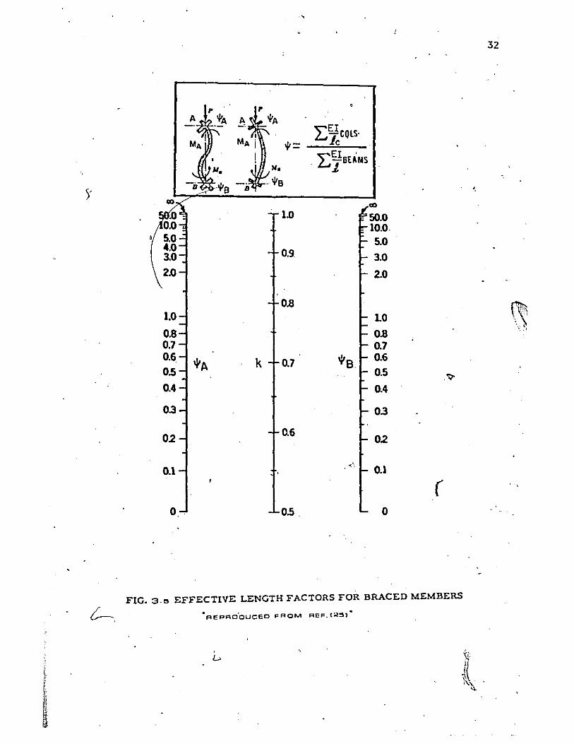
In summary, the following comments can be made concerning calcula
tion of effective lengths:
(1) For columns braced against sidesway, the effective length
falls between 9.u/2 and 9.u ' where 9.u is the actual unsupported
length of the bolumn.
(2) Fqr columns not braced agnins:osidesway, the effec~ive length
is always longer than the actual length o~ the column 9. u
and is more likely to be near 29. or even higher. u .
(3) The use of the Jackson-Moreland alignment charts whiCh are
reproduced in Figures' (3.5) and (3.6) allow graphical detllr-.
mination of the effective length.f~ctors for both braced and
unbra~ed frames. As an example for braced frames, if Doth
ends have very little stiffness or approach ~ = 00, where
~ is defined •. 1: (Ell9. 0) columns
as 1: (El/l) beams ,thenk= 1.0, where
k c le/1u' If both' ends have or approach ~ull fixity,
~ = 0, then k = 0.5. -In determining the effective length
factor k, the stiffness of the beams may be calculated on the
basis of the moment of inertia of th~ cracked transformed
section and the stiffness of the column by using El from
equation (3.4.5'), o~ from equation (3.4.6) for-lightly r~-
inforce~ column$ with Bd = O.
(3.5.c) Slenderness Lim~ts for app.;oximate design methods:
For compression members braced agninstsidesway, the effects_of
slenderness may be neglected when k\/r is less than 34-12NI/N~2.) (NI _ and
M2 arc the design end moments, and r is the rajuis of gyration for the
)
n \.
,
32
2:E1 CQLS. t= ic
2:E1BE ';",S N. .' .J.
Y 00 00
1.0 SO.O 10.0, 5.0
0.9. 3.0
2.0 2.0
0.8 1.0 ~ 1.0 '"
0.8 \" ~
0.8 '. ,
0.7 0.7 0.6
"'A k 0.7 "'B. 0.6 0.5 0.5
.~
0.4 0.4
0.3 03
02 0.6
0.2
0.1 ... '~
0.1
( O. o.s 0
FIG. 3.!> EFFECTIVE LENGTH FACTORS FOR BRACED MEMBERS
L>
~ i: .r r. "\. ~
i~ ~1

33
,
t= L;QiOlS
lc
"'a :E ~IBEflIAS
Ii -co co 20.0 co
100.0 10.0 100.0 SO.O SO.O 30.0 5.0 30.0 20.0 4.0 20.0
• 10.0 3.0 10.0 8.0 8.0 (' 7.0 7.0 6.0 6.0 ' •... ~
5.0 ~A k ~B \~ -I,,: 5.0 \ ',,!
',,'
4.0 2.0 4.0
3.0 3.0
2.0 2.0 1.5
1.0 1.0
). .'
0 1.0 0
FIG.3·0 EFFECTIVE LENCTH FACTORS FOR UNBRACED MEMBERS
-FH:PRCCUCEO FROM~ RGF, (;l:5J i
/

,
34
'colwnn cross soction). M2 is tho lllrger 01: tho ond moments of 11. column
obtainod .by elnstic frnme nnnlysi~. Ml is the smnller, of tho end
moments. Ml is positive if the member is bent in singlo curvntilre nnd
is nogntive if the column is bent in double curvnturo. For compression
membe~s not brnced ngninst sid~swny, the offect of slonderness mny be
neglected when k1 /ro is loss thnn 22 (2) . U
" TIIO upper limit for compression mombers which mny be designed by
the npproximnto method of moment mllgnificntion is U /ro equnl to 100(2}. . u
I'nien kR-u/1' is greutor thnn 100 nn nnnlysis ns do fined in section (10.10.1)
of tho ACI Stnndnrd 318-71 must be used. This nnnlysis must take into
account the influence' of nxinl londs nnd varinble moment of inertin on ,
member stiffness nnd on end 'moments. ' It must also includo the effect of \
deflections on t~e magnitude of bonding moments nnd nxial forces, nnd
the effects of the durntion of loading. The 10\~er slenderness ratio "
limi ts nllow ~ larger percentnge of designed column,S to bo excluded·
from slenderness considerations. Considering the slenderness ratio
k1 /ro in terms of 2. /1; (where h is the depth of the column in the direc-u . U,.' d
tion of the applied bending moment) for rect~lar columns, the effects
of slenderness may be neglected in design when 2,/h is loss than 10 for u
, r' a member braced against sidesway nnd having ze~ restrnint at the ends.
This lower limit increases to 18 for n braced meml,ler in double curvnture
\~ith equal end moments nnd a ratio of column to beam stiffness equal to
one at each end(2S). For an unbraced .member with a column to beam stiff-
ness ratio equal to o~e lit both ends; the ~ffects of slenderness may be
neglected when 2. /h is less than S. This vlIlue roduc~s to 3'if the beam u

3S
I'
stiffness is reduced to one-fifth of the column stiffn~ss at each end of
the member.
The upper limit on slenderness ratio of 2 ·/h equal to 30 for a u
member braced against sidesway with zero restraint at the ~nds. This
1;jh limit' increases to. 39 with a ratio 'of column to beam stiffness equal
to one at. each end •
. 3.6 CmlMENTS
The ,recommendations of the ACI Standard 318-71 which pertain to
column design call for the use of improved structural analysis procedures
wherever possible or practical. In place of such improved analysis it -.J
provi?es for an approximate design method based on the principle of
moment magnification. This is ~imilar to the procedUre used as' part of
the American Institute of Stee18Construction specifications and CSA
etc. After study of the normal range of variables in column design,
limits of applicability were set which eliminate from consideration as
slender columns a large percentage of columns in braced frames and sub-
stantial numbers of columns in unbraced frames. Desi~ers have been
assured (2,20,28) that ove! the appltcable range of slender compression
members; the proposed procedure in the ACI Standard 318-71 is rational,
safe, and reasonably consistent •. ' However evidence of the above mentioned
rationality, safety, or consistency has been lacking, especially with """
respect to sustained lo~d effects. Investigation of this aspect was one
of the most important tasks for the study done in chapter- (6) .
. Because the moment magnification .method calls the attention of -
ii the designer to the basic pljenomenon in slender compression members atld II
f: .. ". :~\
i;~ ~\
~~." ....... ,., \ . ';~

36
allOlis him to evaluate the additional moment re~hirements in those
members, safe design should be the result. However, especially for,
high slenderness ratios, .it.is doubtful if the proposed method is consis-
tent.
Chapt~r (6) contains the results of· the parameteric study of·the
capacit,Y of columns and provides an eva'luation of the ac;curllcy of the
~!oment Hagnifier method. The practical use of this method is also dis'""
cussed in Chapter (7).
. ,

4.1 INTRODUCTION
CHAPTER IV
PROPERTIES OP MATERIALS
In this .cl1apter the relevant properties of concrete and steel are
described. For the analysis of the behaviour of reinforced concrete
frames the information which is required are the stress-strain relation
ships for concrete and steel, the shrinkage and creep charact)'lristics for
concrete, and the strength versus time relationship for concrete. The I .
formulas and mathematical models used to compute these in the numerical
analysis are introdu~ed.
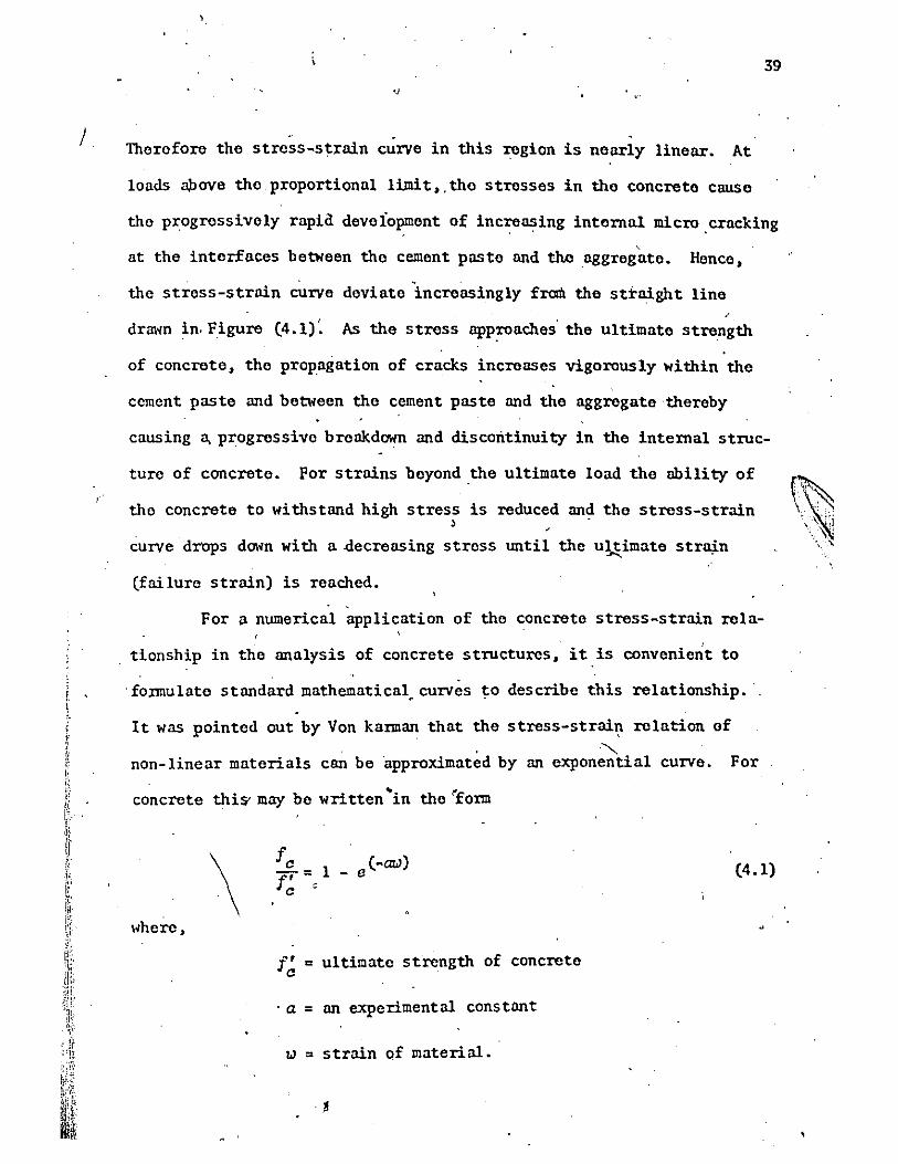
4.2 CO~CRETE STRESS-STRAIN RELATIONSHIP )
Concrete is known to have a non-linear stress-strain relationship.
The general shape of the stress-strain curve is shown as the solid line
in Figure (4.1). The curve begins with a fairly linear portion that ex
tends to about 30 percent of the ultimate strength; then gradually deviates
from the straight line up to a peak at the ultimate strength of concrete.
After that" the curve descends in a gradual manner until the ultimate
strain of concrete is reached.
The non-linearity of the stress-strain relationship of concrete'
has been attributed largely to' the fact that the failure of concrete under
load takes place through progressive internal cracking. At loads below
the elastic limi~ (called the proportional limit of concrete) ,"'the stress'
concentrations within the hetrogeneous intornal structure remain at a
i sufficiently low level that only relatively minor micro cracking occurs. ! \
\ .Ii [,
37
~ ' .. ~""~ \} ',I
,\\1 '.:'\

'-
,
:
t/~ 0 ~
~1.~ • • ~ 0
0.80
. 0.60
0.40
0,20 ~
I 'I
'I ~
Vf~ :2tEc/Eo ) -(Ec IEO)2 .\; /~ =10 • 0.15a::c-fd~-fJ
\ /" -:;..:::::.:::{. ' '" - \ - - \I ......-...,
~
, \, , . _ '\-'-r'-' , ,--.: I r/ ~ fCIfc:-4.50C6079.-a9e;I'~ .7.6164509.tr~-4,OO22754-1(}'i~·1.13~103EC '/ '..
I '/ :
/'1'f i CRYSOALE
. _____ HOGNE"STAC
r _o_._WHITNY
• CYLINCER TEST AT :;;zB CAVS
0.00 V , I I I I I ,I I 000 OID1 Eo.Q02 0.003 Eu 0())4
CCMPFlECBlve STRAIN
FIG,04.1 CONCRETE STRESS-STRAIN
REL.ATIONSHIP,
~";4 .-~"#
E (in/in) c
'" '"
J
39 .J
Therefore the stress-st:rain curve in this region is nellI'ly linellI'. At
loads $ove the proportional liJnit,.the stresses in the concrete cause
the progressively rapia deveiopment of increasing internal micro cracking .' ,
at the interfaces between the cement paste and th.enggregnte. Hence,
the stress-strain curve deviate increasingly from the straight line
drmm in. Figure (4.1) ~ As the stress app:roaches' the ultimate strength
of concrete, the propagation of cracks increases vigorously within the
cement paste and between the cement paste and the nggregatethereby
causing a, progressive breakdown and discontinuity in the internal struc
ture of concrete. For strains beyond ,the ultimate lond the ability of
the concrete to withstand high stress is reduced and the stress-strain , .
curve drops down with a decreasing stress until the u~imate straj,n
(failure strain) is reached . .
For a numerical application of the concrete stress-strain rela-
tionship in the analysis of concrete structures, it is convenie~t to
'formulate standard mathematical. curves to describe this relationship.
It was pointed out by Von karman that the stress-strai~ relation of
," non-linear materials can be 'approximated by an exponential curve. For
concrete thiS' may be written 'in the 'form
\ where,
f' c ultimate strength of concrete o
. a " an experimental constant
l,) " strain of material.
(4.1)

<, 40
< ,
The exponential tenn of equ3;tion (4.1) can be expanded in series fonn as.
e(-QL1~ = 1 --azu + (QL1)z/2! _ {QL1)3/3! +
Hence equation (4.1)
"here,
can be simplified as a series ~
fa
r= 0,
,
"
°llJ t a lJZ 2
n . L o.lJ't.
i=l 't.
i = 1,2,3-,4, ...
+ °3lJ3 ,+
O. = experimental constants 't.
i O.lJ 't. +".
\ •
(4.2)
Generally, i t iS~. nsidered ,that a fourth order polynomial wnl
yield. a sufficiently acc a~e approximation of the actual stress-strain " ,
characteristics of concrete. The 'constants C. are detennined from a '" 't.
, ,
least-square fitting of large ~umber of test ,data. For the concrete
used in the research done at HcMaster University; tI're values of the
constants were found to be
.' C1 = 1.1902628 x 10³
, '
c = -4.8022754 x 10 5 2
,C3
= 7.6164509 x 10⁷
C4
= -4.5005079 x 10 9
In Figure' (4.1), the experimen,tal curve reaches its ultimate strength
at a strain of 0.00215 in/in. It was then aroitrari1y gradually decreases
, until the ultimate strain of 0.0038 in/in. is reached at a stress of
0,85['. This results in very nearly the same magnitude and position of c

the resultpnt o~ the force in the compression zone as was found expe~-" .
mentally by Hognestad. . '
A good 'comparison of the experimental strcss-
s tfain relatiOl).ship with the Hognes tad's and \'lhi tney' s curves is 'given
in reference (31).
The stress-strain relationship is changed with aging of the ,
41
concrete due the increasing strength. DrysdalcC 10) dcriV~d stress-strain
characteristic's for various strengths of concrete at different, altes to
facilitate its application to the num~rical analysis of reinforced con-
crete columns. The incl1lase in concrete stx;ength with age was expressed 'I '
"
as a ratio of the 28 day cyl~nder strength. For concrete stored at 50\
'relative humidity, it was shown(lO) that nearlY,< all increase which woul'd V\ occur in the first two years took place within 5 months after pouring.
Then' the increase in ,s,~rength after 28 days was assumed, to increa;;e
linearly to its final strength at 120 days after loading the columns.
For more infonnation about the increase of strength and the change in
the stress~strain relationship with aging of the concretQ refer to
reference flO)
Although the developed computer program could handle the criteria
of the change of'strength and stress-strain ,relationship of concrete, , , '
this 'criteria was not conside~d in the analysis in chapter (6). This
provided a conservative basis' for evaluating design procedures. How
ever this feature of the analysis had to be included when comparing
predicted behaviour with test results.
, ,

~' '
, ,
\
42,
".3 smUSS-STRAIN ,lU1LATIONSHll' FOR I\UXNPORC ING STUlIL
1110 roinforclna stool 19 llII~wnod to }Invo nn ldonllzod oh;:lt1c
I'llL1tic ,stross-:ltrnin ro~,ntionshill' '1110 off9ct of !ltrnin"hnrdoning hns
, hO~~I~llloctOJ. Iionco"tho, c~Irvo,cnn bo dopictod n!I a Ilorfoctly straillh't
Hno up to tho yiolding 1I0int follollod by a ronion of constant stroS:l.
'1110 ~lII,tH'O ro lationship botwocn's tross oml strain cnn bo ropro~ontod by"
tho folloldnn oquation,
/
, ,tJ +tJ -IIJ -IJ 1 f .. f. (lop l! o· 1/ ) '0 y 2tJ/I
Ilho1'O,'
~D,f!J ., lIJros:I and yiold :l~ronnth of stool rospoctivoly
tJ ,tJ .. strnin and y!old :ltrnin of stool 'respoctivoly o y , ,
I'igU1',,o (4.2) shOlls"tho thoorotical ond a typical oxporimontal stross-
(
• strnin cun.o(~). 1110 small difforonco botlloon tho twocurvos, is n~
~,slilnincnnt o~copt poss,illly whoro plastic bonding momonts aro incorporatod .~ . .
into tho Malysis.
-1.4 CONCRETE SHRINKAGI!
Shrinkago of concro'to is tho volumotric doformatlonllhich, occurs,'
in tho nbsonco of load or ,rostraint. It is duo mninly to 1'055 of " '
mois turo from tho concroto by Idiffusion, Or ovaporation from freo sur
fn;::es. 1110 oxistenco of a moisturo grndient wi thin tho concroto causos
differentinl .shrinkngo which cnn induco intornal s trossos. 1l00lovor, this
effect is not considorod in,this study.
Tho magni tudoof sh~inko.go strnin is of the SlUno ordor Il;S tho
clastic 'strain 0'1' concroto undor tho usual rango of working strosses.
,,'
'"

fs (ksi)
7 O.
m m w II I-
'" 6 O. m ., -' w w I-m
50.
L. O.
3 O.
2 O.
1 O.
, , , I I I I I I I I I I
,I , I I I I I I I I
• I I I I I I
Y I ELO STRENGTH
6 rEST RESULTS
___ THE ORETICAL
43
.
~,
"
onL'~----~ ______ L-____ ~ ______ ~ ______ ~ ____ ~
0.00' , 0002 0.0()l. o.oos 0.008 0.01 0.012 TENSILE ~S [INflN)
FIG. 4.2STEEL STRESS-STRAIN
RELATIONSHIP' p
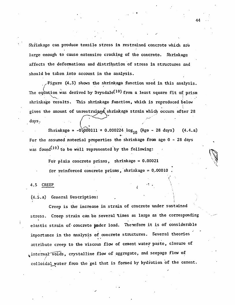
Shrinkage can produce tensile stress in restrained concrete lihich are
large enough to cause ,extensive cracking of the concrete. ShrinkagQ
affects the deformations and distrii!.utionof stress in structures and
should be taken into account in the analysis. "
44
, -Figure (4.3) shows the shrinkage function used in this analysis.
The eCJ.Ll;ion ~as derived by Dry~dale(lO) from a least square fit of prism ~, I '
shrinkage results. This shrinkage function, which is reproduced UOlow ~ \
gives the mnount of unres~r~:hrinkage strnin ~~icl} occurs after 28
,days: r ' Shrinkage " -O~~lll + 0.000224 10glO (Age - 28 days) (4.4.a)
.' For the assumed material properties the shrinkage from age 0 - 28 days
lias found(lO) ,to be well ~presented'bY the following:
For plnin concrete prisms, shrinkage = 0.00021
for reinforced concrete prisms, 'shrinkage" 0,.00010
4.5 CREEP
(4.5. a) General Description:
Creep is tho increase in strain of concrete under sustained
stress. Creep strain can be several 'times as large as the corresponding
clastic strain of, concrete ~der load. The'Wfore it is of considerable
importance in the analysis of concrete structures. Several theories , ..
, . attribute creep to the viscous flOli of cement wate~ paste, closure of
~ inte'rnaYVOlds, crys talline flow of aggregate , and seepage flO1~ of I
colloidal water from the gel that is formed by hydration of the cement . .-..

~
./.
'-
o "
, 400
-
500 yo ... •
• ",.-t' q.'
~ ID , 0 ~
• ; ./ ,~ • po ~v
~ " 300 • c
<I. II t-III
W CI <l: l! Z -II I III
200
100
/
/ /
,..-/
• •
..... ,..-...
• ~HRI N KAGE =(00111 +OOOO224Iog(age -28)
. _. - --. . .---.... . ~ /.... U ......
./ ...... .... ;r
..... PRISMS WITH STEEL REINFORCMENT .;.:'" .
0.0 a 1,r J I \ I I 35 < 56 140 365\ 700 lWO
)
AG E OF CONCRETE IN OAYS
FIG.4.:3"SHRINKAGE FUNCTION .
'I'
~ . .-..
'. ,,/..~ t;~/' ~:-<~p
... V1 -
46 ,
Creep is influenced by the aggregate-cement ratio, water-cement
ratio, kind and gradation of aggregates, composi1:ion and fineness o'f
cement, age at time of loading, intensity and duration of ~ moisture content of concrete, relative humidity of ambient air, and size
and, shape of the concrete menber. The ra~e of creep deformQ.tion is
relatively rapid immediately after loading and decreases exponentially
"" with time. Concrete also exhibits creep and shrinkage recovery upon
, , ,
unloading. This latter aspect can be explained as the release of the
increased strain energy stored in gel during creep, and the readjustment
to reach equilibrium of vapour p;res~ure), '
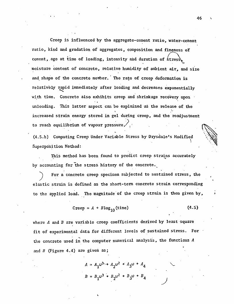
(4.5.b) Computing Creep Under Variable Stress by Drysdale's Hodified \
Superposition Hethod:
This method has been found to predict creep strains accurately ~
by accounting for -the stress history. of the concrete •.
) For a concrete creep specimen subjected to sustained stress, the
elastic strain is defined as the short-term concrete strain corresponding
to the applied load. The magnitude of the creep strain is then given by,
Creep = A + BloglO(time) (4.5)
where A and B are variable creep coefficients derived by least-square
fit of experimental data for different levels of sustained stress. For ,
the concrete used in the computer numerical analysis, the functions A
and B (Figure 4.4) are given as;
A = AIlJ~+ AZlJ2 + A3lJ + A4
B = BllJ 3 + BZlJ2 + B~ + B4

I
~
w ~ I-~o
r c-o J
m + <{
II n. w w II: , u
8 o N
o o
. In
\
'\
-
, , " "
0 0 0 ~
" \ • \
\ \
\ <t"\
\
0 0
,- In
\ \ \ \ \. \ \ \
o o N
m a r • 2
<t 0: I-
8 m ow ~I-
w 0: U Z a u ~
o~ ~I-
I-0: a 1: m
o ~-
\ \. \ \ \
o 1
o o ~
\ Ig
0\ N
·1 \ \
0 0 0
0 ci
l
47
z 0
I-
U ~ Z ~ - ',', ,. . '~"," ;-, 'l':F
::J .... ".,!
IL
] n. w w It
U

-
\~here ,
" , W " Elastic strain of concrete corresponding to the
sus tained stress.
Al " ~1.03050 x 10⁶
~" 5.748870" 102
A3" -3.77674 x 10⁻¹
A4 " -3.072250 x io-6
Bl" 1. 858390 x 106
B2 " -1.012295 x 10 3
B3" 1.5213225
'B4 " -7.986250 xlO-6
48
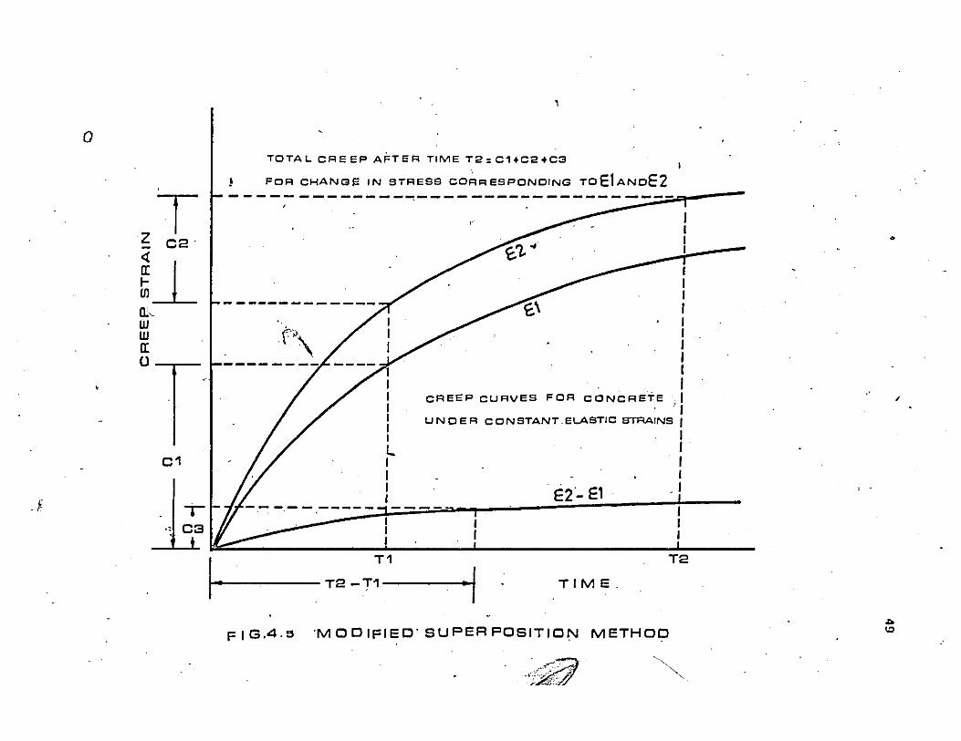
The curves fo. functions A and B are shown in figure 4.4. The procedure'
for using the modified superposition method is i:11ustiated in Figure 4.5.
If an element of concrete is loaded' so that the elastic strain
is wI and maintained at this stress'fl for a p~riod of ~ime'TO to Tl ,
the amo~t of creep which would occur would be Cl
. If an increased
stress f2 resulting, in elastic strain w2
is then maintained for the
~eriOd /T 1 to T 2' toe amount orcreep which would occur during this time
if the specimen had been loaded to f2 at time TO is denoted as C2
• To
account 'for the change in stress, C3
is the amount of creep which would
occur for the change of elasti'c strain W2~Wl over a time interval 'from
zero time to T 2-T 1 ~ The creep which occurs during time T 1 to T 2 is
C2
+C3
• Similar evaluations are perform~d for successive time intervals . .
and added to the previous value of creep strain to give the total creep.
This method of modified superposition will slightly ~derestimate creep ,:\ iI,,\ ,'\
\
"
o
F
T ~ C2
~~ 0;, W w 0: U ---y_
C1
£T ': C:3
,
TOTAL CREEP AFTER TIME T2:C1+C2+C:3
} FOR CHANGI" IN STRESS COR"'ESPONOING ToE1ANOE2
-------------~--------------------
- ------------
I I I I I I l I I I I
I I I I I I I I I I
CREEP CURVES FOR CONCRETE I " I
UNOER CONSTANT ELASTIC STRAINS I I I I I
E2- E1 I
~~~--------------~------~--------------------~-------I T1 I T2 -T1 I I T2
TIME"
F I G.4.5 "M 0 0 IFIEO' SUPER POSITION METHOO
<--'(j' ",/;:0-;.,;z(:~/~
"~'-
~
.. <a
,

.. i
~or increasing stress. The effe·ct of creep recovery is not taken into
account.
4.6 CONCLUSIONS >
so
The mathematical mo!iels of the mechanical properties of concrete
and steel have been incorporated in the computer prog:r9ID for the analysis
of reinforced concrete frames. A listing of tlHs program is cont:dned
in Appendix. CA). In interpreting the. predicted influence of the non
~inear reasponse of reinforced concrete,· it is obvious that large
variations in quality and behaviour exist for different concretes. The
concrete which was used to obt:dn the experimental data from which the
mathematical models were derived was intentionally designed to have a
<? higher than average creep rate. This was accomplished by grading the·
aggregate so tIlat a relatively lOl~ aggregate to cement ratio was obt:dned
while maintaining an acceptable quality of fresh concreto. The result
is that predicted deformations should be slightly in excess of those
lihich would be expected for average quality concrete. This assures a
slightly conservative basis for judging the adequacy of present design
procedures.

! I , l I
"
DESCRIPTION OF TIlE COLUNN ANALYSIS
AND COMPIITER PROGRAM
5.1 INTRODUCTION
The nnalytical technique which was used in the numerical column
• analysis is discribed in this chapter. Also discussed-is the computer
program which was developed to provide theoretical predictions of be/
,haviour and cppacity for rei,forced concrete columns sUbjected to various
::::::(~~::;,,:,:: :::~U::::::":::i:::Y ,:::.:::~~ '~ / ",\
V \
5.2 NUMERICAL l-Kl/olENT-CURVATURE, NETHOD OF 'ANALYSIS
The basic form of the method of, nnalysis is described in this
section as foqol~s:
(1) The members of a structure are divided into a number of
small disciete element lengths which' in turn are sub-
divided into ao'finite number of element strips at each,
cross section perpendicular to the direction of bending.
(2) For ~any arb~otrary set of strains at the extreme fibres of
the cross section tne compatible stresses are evalu~ted'
from the known stress-strain properties of the materials
assuming a plnne strain distribution.
(3) The internal n:xi.al force and bending moment for _the given
strain distribution are computed using a numerical integra-, \,
'tion proce,dure. and are compared to the externally applied
'-
S1

S2
load and bending moment acting at the geometric centroid, "
of the cross section. If equilibrium does not exist. the
assumed'strnin distribution is repeat~dlY altered until
external and internal loads and moments differ by less than
some permissible error. )
(4) Member deformations at the mid point of each member clement , are then computed for the average load and moment over the
"
,element length.
(S) The compatibility between deformations and forces at a
50int in a structure are then. estnbl~shed by another trial
and error iterative process which involves the analysis of
the whole structure.
5,3 NEI'/TON-RAPHSON NETHOD
Determination of the compatible strain distribution for a set of ':-
applied loads and moments is made difficult because of the non linear
stress-strain properties of concrete and the inter-~ctive effects of
~.~" ... :\~' :.,.,' .. '~,"''' .• . " '.~" " '\'
:' "
, ,I load and moment.' The Newton-Raphson Nethod of successi vo nppronmat1on (
can be conveniently employed to achieve convergence to the compatible 1 ,
strain distribution. The application of this method is discribed below. ,
The internal axial load and bending moment can be determined
provided that the strain distribution is defined' by the extreme concrete
fibre compressive strain and the curvature. Hence
.... (5.1)

whoro
~l Q extreme concrete fibre compressive strain
-~ Q curvature acting over the cross-section
P* ,M* " intornal axial load and bending moment
resllectively
P,M" load and moment function respectively.
53
By using Taylor's theorem with linear terms only, ~ -
whero,
ap" '. ar-
so that,
p*cp+ap*dtJ " ~ - I " 0 I
- - aM* 'aM* M* " M + -- dtJ + - d~ . ~l I a~ -
•••• t5.2)
P,M-= known axial load and bending moment for a
known ~ and WI
aM* --" , del> rates of !;bange of P* and M* for which cj> and ,
WI are sought
, dtJ,dcj> = in~rement of strain and curvature necessary to
produce P* an!i N"
•••. (5.3)
Wi = ~l ~ dtJ1
where 9* and wi can be used to compute P* and M*. Equation (5.2)
can also be
•••• (5.4)

54
Equation (5.4) may be rewritten as ,
{Q*} = [E*] {W"}
Therefore, if the matrix E* and the load vector Q* nre known, the incre
ment vector W" can be" easily determined if.E·-l exists. Hence, the
increments of curvature and strain contained in tho W* vector'can then
be substituted into equation (5.3) to obtain a new set of "'1 and 4>, and
therefore a new set of load and bending moment. The computed P and M
are then compared to. the applied P and 1<1, and, if the difference between,
them is less than some allowable error, the process of iteration is
terminated. Otherwise, the iteration is repeated by substituting -into
;;quation (5.2) the computed P and U as new initial values of P and M, , and the comp11ted values of "'1 and <l> as a new set of WI and ~.
The application of the Newton-Raphson method has been only
briefly introduced here. For more details and for selection of incre-
ments for convergence control refer to sections (5.6.c) and (4.4) in the
thesis by Tan(31) and to the paper by Robinson(29).
The Newt~n-Raphson method of conv~rgence was shown to be very
fast. This was established by running the computer pr~grnm USing
several ite;rative techniques. HOliever, at loads near failure the ten
dency for the Newton-Raphson method to overestimate changes in strain
sometimes resulted in non convergence. This no~nlly indicates section
failure but in these cases was shown to be a convorgence problem. There-
fore.a backup iterative procedure lias used when convergence had not been
reached within some specified number of trials (normally 100 eycles) •. i
This other iterativ~method for adjusting the strains at a cross-soction.
<.

., f]
'.
to balance the ~ternal load and moments was specifically designed to
facilitate convergence,on the equilibrium values' near the failure of
the columns. Using the previously fOWld set or" stable ?jtrains as, a
. starting point, the strains after' each cycle of iteration' monotoriicaUY
converged in ~ asymtotic manner. This method was used rather than the
more conventional OScillating type of convergence. The latter method
would fail to·converge as the column approached instability if an over-
csti\llUte of the strains ltas made. " '
Column failure was indicated by the inabi,lity of the two itera-
"
ss
tive'techniques to converge, on the required equilibrium strain distribu-, . ,
tion, within a limited nlllDber of cycles. Tho limit was sot at; 100 cycles ]
fo~ each method. This was 8 to 20 times" the nlllDber of iterative' cycles
required for conv,ergepce at more stable loads using a very poor initial
estimate' of the strain distribution. Therefore, failuro to converge
meant that' the co~~ at least was very near fail'ur:,.' , To check on the convergenco of the analytical solution, tho rate
of change of defor\llUtion was plotted against load. From this it could
easfly be seen that fail~ wourd lie somewhere between the last stable ,
load and th~ point of infinite rato of change of deformation Ithich could
be predicted' by ~awing a t~gen:t to the last point on the piotted curve.
This, practice assureltqat convergence failure did not result in large
underestimates of colw:m capacity. There was no possibility of over-, .
estimating column capacity due to inadequate convergence indications "I .. qecause there would be no other stable position beyond the actual ultimate
,
. capaci ty of the column.

•
,
1t1 Iho lH'ovlolls noctlutI~ It hu~ hootl ~ho"tI thllt cOlllllutlhlo
"l'rurlll;ltl.~"~ cun bo l'olltlll for ull tho 90Ctl~tl9 I~hlcll UI'O nubJoct~ll
'~I'l'd floJ 10n,ln, 1110 llofol'lUlltlonn 1'01' tho "tltlro ~t\'\lct\ll'o.: nnll thl
IU;hh ou ull olomotlts limy ho foutlll hOIll cotlVontlollnl ol\lntlc 1I1111\)'no, if
"1'1' 1"'1'1'1 uh' I'I'UCO!l!lOS hllVo hoCl' ll"vI9{11l to 1I1'ovllio !It I frllt!!!! VUillO!!,.,
Tit" ",\111 vul('lIt !lHfrno~!lon rl'1 mHI 1\,1 fo\' Ull O\OIllOtlt of U ntl'uclllro CIIII
hI.' ,11.'\'lvI',1 (1'<1111 chnrnctol'l!ltlc C\II'VO~ for IIIUll\oi,t-cllrvuturo (1\'l"N/~) unJ
IU;hl-uxlul ~tl':tltl (~'/bl'I'" 1 \) I'l'lutlonshl(l!l, .. ux U
If IIU e9tllllatoJ !lot of o,\ulvulont ntlfnlo!l!l I!! ul'bitrnri\),
"",11111<.',1 fut' ('nch dl.'l11out of U !ltl'lIct\ll'O Hhlclt 19 !luhJoctClI to II (lul'ti':l1-
luI' 1)'(11.' of 10a,HIIIl. tho forc"9 111\\1 JoforllllltlU1l9 oll'onch olol11ollt 11\(1)' bo
,'alclllal",1. 'l'hl.'l1 th(' cOIIIl'ntlblt' !ltl'ulu dlHrlhullotl (01' oqullihrlllm or ,J
" ,('Xll'l'I\;\I.,.m,I'ltltot'unl lonll!l CUtI ho tJ·~J to l't!cnl':1I1uto tho o!ltlmntoll
<"j\llvall'l1t ~tlffn(,!l!l Itl :m Itorntlvo !lcqucuco untlt tho chunHo In tho
~{lrrlll'!I,e~ nppt'oudle~ UII UCCl'ptnlllo V,tIIlO, 'l'hl~ sot of"c,\ulvnll'lit
~I I rfll"~~"." Call he lI~o,1 to predict tho bohavlour or ~tl'llctUt'OS, 1I0NOVOI'. , . II h 1I0~l'~,aI'Y to Jevelop tt .:ellol'nl compulor proll\'(ull illcorllor(\~lnlt tho
,.I"" "I' "11.1'111"" modlfli::ttlon to :lc,\ulro tltl' corl'oct got IIf l''1ulvttlc'11t ,
,I I nl1"" fOl' the ol:l:ltlc {\1Htl)"b of llloln,tl.: COl1Cl'oto "trllctllro"
1'01' I'r:lctlcal rO:l~on~ it Nn, dl'cldad ,to Ilmlt"tllo nnnly!l" to
,""'t'"' I<hl't't' 110 plii,~lth' htnl:(' b :lllol~()" to fOl'm In thl' ~tl'lIctl1l'l'. ,I\~ (\
"""\111 tI\\' ('1';\11\(\ may bo 10111101\ onl)' lll'lol~ tho ultlm:tto cnprtclty Ill' nl1Y
,,<,,"t Illl1 , 111.'1"'1', for "tl1,llo~ or f:llll1ro. fal ltll't' b "of,lnc." Nhol1 UllY
1'",.t or the 5tl'Ul'ture 1'0:ll.'ltO" It :I ll1tim,lto capacity un" no nCCOlll\t b
1,,1--t'rt for th(' n,ldltltl11al I'cdbtrlbutlon of 10aJ Ilhich call occllr ""0 to
)

plastic deformation. Th~ reason for th~s limitation is that when a
plastic hinge has form~d in tho structure, tho hinge will allow an ,~
undefined incroase in rotation at the hinge without fu~er increase in
the moment capacity of the structuro under incre~ applied loads:
57 '
, Thereforo, the stiffness modification procedure cannot insure a definito
set of equivalent stiffnesses for the,whole structure without incorpora-,
ting a modification ,to the discription of·the structure.
The steps of stiffness modification are summarized below:
(1) From the geometric properties of e~ch element, t~e cross
section of each element is subdivided into a number of
clement strips.
(2) The elast;ic axial stiffness !,A and flexural stiffrless EI
are computed using the following values:
Ec ~ 33{~)1.5(f~)1/2 , (~ ~ 145 pcf for concrete) .
A = gross section area of cracked transformed section.
I = moment of inertia of cracked transformed section.
Then these calculated estimates of stiffness are substituted
into the clement stiffness matrix for each element.
(3) Ni th -the el,ement stiffness matrix for each clement formu-
lated, the assembly stiffness matrix for the whole structure
is assembled and used to determine the displacement and
force vectors for the structure.
,,' (4) Nith the defl"ctcd shape of the structure known, the secon-
dary bending moment due to deflection of tlje members
(p.t:. effect) arc computed and added to the primary moment
acting at the center of the length of each element.

j"
58
(5) For tho calculated ben~ing moment and axial forco acting o"n
n, given eloment cross-section. tho New"ton-Raphson method is",'
ompleyed to dotermine the unique strain distributien for a
each olement. thereby permitting the cemputation of the
modified values of EI and EA. ,For the sustained loading "- '
condition. the shrinko.ge and creep deformation and stress
history nre included in the l.Il;Iique strain distribution which
provido equilibrium of the section.
(6) The new equivalent stiffnesses EI and EA for each clement
are then compared to the previous estimates. ' h'hen the error
between them is less than r. for each ~lement. tho set of
modified stiffness is said to have converged to the equiva-
lent stiffnesses for the structure. and the process "of
iteration is terminated. Othendse. the new stiffnesses aro
substituted into the element stiffness matrix for each elemen~
and the processes in 3. 4. 5 and 6 are repeated. , ~
Generally for loads applied bel!llt the 'Ultimate capacity of the
s~?C~_r9' the stiffness cr\t,eria can be easily satisfied within" a felt
cycles of iteration. Howeve~ for loads ncar ultimate capacity of the
structure. or when creep. shrin~ge and stress" history were included. the'
analysis usually required more cycles of iteration. This was dUel to the
large modification in equivalent stiffnesses required ,to account for these , ,
large inelastic deformations.
I
, "

)
i:, I; 1[,
/
-1-..
5.5 COHPlITBR PROGRAM ~ _
A computer program was¥dev~~in this study to facilitate the
method of analysis 1iscr~bed above. Parts of compute; programs from
Drysdale 00 1, Emery (12.), and Tan(31) wc.re- adapted for usc in this program. ,
It consists of a main program and four subroutines, which are "BLASTO",
59
, "~ll'HI", "BHPCAL" and "CREEP". In Figure (5.1), the location and function
of 'each sub~utine are shown in a flow chart. I
(5.S,a) Subroutine "ELASTO" was developed by Emory(l2.~ at the UniVersity
'of Bri(ish Colwnbia, an~ is ~ plane frame program using a banded matrix
method~o solve for the displacements and forces in plane frames. The ~
loading points and the proper¥"es of each member in the frame must be
specified. l
(5.5.b)
section
In Subroutine "~ll'HI" "the Newton-Raphson method discussed in
(5~ utilized to :~acilitate convergence on a ~que strain
distribution for a speCified axial force and bending moment combination.
If the NC\~ton-Raphson ~!ethod fails"to converge wi thin 100 i terati ve cycles,
the alternate method is used to check whether the column has failed or
whether there ~as only been a convergence problem. _ When both convergence
methods fail to converge within 100 cycles the column is assumed to have
failed, as discussed in section (5.3).
(5.5.c) Subroutine "BHPCAL" operates the numerical integration proce
dures. Its function is to compute the inte~alaxial force and bending
moment for a concrete cross section subjected to a given strain distribu: •
tion. The following sign conventions are used in this subroutine,
(1) Compressive stresses or strains in concrete or steel arc
positive. (

Compute Elastic EI &'EA
Elastic Analysin---------~~ .. -----.g Forces, Moments Call Elasto and Doflections •
\
Find Compatible Set of deformations for the applied~loads
Call Band
cuI ate ~econdary
Bending Noment
Call NpHI -- ' Call BMpCAL
EI", M/$
EA '" P/Waxl.
CALL CREEP
RETURN TO THE ~IAIN , PROGRAM AND CONTINUE
FOR THE NEXT STEP
No
Fig. (5:1) Flow Chart for the Computer Program
60

•
,
(2) ~tance from the neutral axis of the section towl1rds the
extreme compressivo fibre in the concrete aro positive.
For more details about the computations .and operations within
this subroutine, refer to reference (31) pp. 97-105.
(S.S.d) Subroutine "CREEP" utilizes the Modified Super position method
for creep calculations which was developed by Drysdale(lO). For cases
61
\
/ where sustained loads are included, this subroutine is called upon to
calculate and ~tore the creep strains £or a specified increment of time.
The computational steps for this subroutine are summarized as follows:
(1) The ad~tiona1 shrinkage strain in concrete for the speci
fied time increment is computed by equation (4.4).
(2) The loads and stress levels acting on a concrete cross
sectio~ are assumed to remain constant for the specified
increment of time. The elastic strain acting at the cen-
troid of each concrete ~lement strip of the section which
were computed and stored in s'ubroutine "BMPCAL", are then
transferred and stored in this subroutine. The creep strai'ns )
for each concrete element are then. computed by the modified
superposition method.
(3) For the next time interval, the stresses on the clement strips
may be different from the previous 'values. These changes
may result from chang~s in stiffness due ·to the sustained . . .
,2.i load deformation. Tfy non linearity of ~reep versus stress
'also could ~ause a redistribution of ~tress on a cross section.
Therefore, for a neli set .of elastic stra:i,ns after the first
time interval, the stress history must be taken into account.

(4)
"
The creep strains including the effects of stress history
are calculated by the mld,fled superposit~on method. ,
given by,
the time effect~i~ The' total inelastic strain due to
62
W g'W total crcep
+!J}' +!J additional shrinkage st.ess history L '
This total inelastic strain is transferred ~o subroutine
"BMPCAL" for the computation of the clastic strain of
concrete. \, , '
Appendix (A) contains a listing of the computer program which
has additional explanation in the form of comment cards.
)
5.6 . USE OF COMPUTER PROGJW.I
,The computer program was set up to handle various types of plane
reinforced concrete structures from very simple structures like simple
beams or single columns to very complicated multistory multibay frames.
Inspite of the iterative nature of the program, it was found to be
fairly economic to use. The program was written in FORTRAN IV Language ,
and lias pro&!ammed to roo on the CDC 6400 computer at Mdlaster University,
Comp~ter Centre. Only minor language modifications would be required to
use this program on other types of FORTRAN IV reading computers. , In this program the members of the structure a(e divided into a
• • number of elements. This number is determined from the accuracy required.
~Iore elements result in more accurate results witq, of course, the penalty
of requiring more computational time. Accuracy studies were made to de
termine the number of eie~nts required for different loading conditions ..

c'
p •
Ithen the frame has been divided into elements, the following
numbering rules should be followed in setting up the model of the
structure:
•
(1) Assign joint numbers and element numbers to all joints
and elements. '
(2) Assign numbers for each possible movement (displacement)
(3)
thrd~ moveI
axi18.1 and
at each'joint of the divided structure. The
ments possible for plane /r:rare rotation,
trans~erse displacements. ~' ,
All ±trai~ed displacements'must be assigned number zero.
(There,ore for a fixed base assign three zeros, for a \
hinged base assign two zeros for the axial and transverse I
displacements, for a roller base assign one zero for the
63
transverse displacement, and for a free end or non supported
j?int (nodal point) assign no Zeros and give numbers to all
, three displacements.)
'~(4) Loads can only be located at nodal" points (joints between
elements) ..
(5) Those clements which require modification of their ,stiffness ,
are numbered first. (Note: It is possible to include
members which are designated to remain 'elastic throughout
all loading stages).'
Rules I, 2; 3 and 4 are required for conv,entional matrix manipu
lation and can be found in textbooks on matrix structural analysis. . '
Rule 5 provides the computer with the addresses of clements \;hich need
no modification of their stiffnesses.
(
i •
\ <,
64
1'he procedure for. pi'eparation o~ the Data cards along Idth un .
illustrativo 'example are describod in Appendix (A).- The program.listing
also contains.comment cards te assist in this process. /
5 • 7 SlJ!.IMARY
The genoral method of unalysi£ and mode of operation of tho
-computer program hus beon described in this chapter. Details ef speci-- .
fic aspocts such us modollingof material properties have ~oe~ previded
in previeus chapters. Chapter 6 contains' the analytical results ob-.
tailled usi11g the above method of analysis. The validity of this techni-
que has been previously(lO,nl) verified by comparison Hith test results.
Therefore it is suggested that the information which is presented is an
accurate prediction of actual behaviour .of reinforced concrete frames.
As such,'it p;ovides much.more information to evaluate col-umn design
proce~ures than could bo practically obtaintd from test results.
'-.
':.

\ . ,
)'
QIAP.TER vJ ' DISCUSSION OF ANALYTICAL RESULTS
,6.1 INTRODUCTION
As was mentioned in chapters (3) and (5), the aim of this study
is to 'evaluate tho design procedures for reinforcod concrete col~s.'
The tiCI Standard 318-71 (2) "H::i~!ENT Wi.GNIFIER ~!Ern~D" was selected as / thebas~s for this evaluation.
To carry out this evaluation for the ACI method., a study of the'
different parameters affecting the design of a reinforce concrete
column \~as done. It was found -that the most impo ant parameters that
need to be studied ate:
(1) The slenderness ratio (kR. /r). u
. ,
(2) Level of sustained loading.
(3) ,Ratio of steel reinforcement.
(4) Initial end eccentricities ,of the load.
(5) Ratio bet\~een the t\~O end eccentricities. , , ,-/
(6) The behaviour of the column as part of a structure.
The study of the above mentioned parameters required more than'
one hundred columns to be analysed individually and 'in groups. For the ,,'
evaluation of, the parameters. the study was divided into six series
labelled (A). (ll), (e). (D), (E) and (F)~. In this chapter the results
"for the six series are presented, discussed, and evaluated.
In Chapter (7) the general and final conclusions of the study
undertaken in this thesis 'are given.
6S

66 "
6.2 DESCRIPTION OF THE METHOD OP ANALYSIS
IHthout doubt safety'is the most important criteria for any
study involving an element which is considered to be o~e of the most im-
portnnt structural members., Columns' are probably the most Important
clement in a structure.
The safety factor for an element can be determined by dividing
the failure load by tht actual design load .. To .20inpare actual safety ,
factors with .the safety factors predicted by a specific design method,
the design load should be the s" Then the comparison between
actual failure 10a4 and that predicted by the design method will ~ , --the real difference between the actual safety factor and the one
by the design method.
the
indicate
assumed
For the different study series,undertaken in this thesis, the
design load was taken as the design load specified by the ACI Standard
318-71 "Moment Magnifier Method". To determine 'thiS' design load accord
tng to the ACI, for a column of giv~n'geometry, including the geometry
of all other members of the structure, the level of , dead load to live
road must be known (or assumed). For the knOiffl level of sustained
loading, with the known (or assumed) end eccentricities, the ultima~e
capacity of the column for known'material prop~rties can be determined , using the iterative method of moment magnification by the ACI. Having
f
obtained the ultimate capacity of the column all ~he proper capacity re
duction factors, and load factors should be applied to obtain the design
load. Therefore knowing the ratio of the dead and live design load, the
level-of dead load and live load could be determined.

\ 67
The technique of loading to failure using the computor program
(which was described in chapter 5, was essentially loading ·the. column
with constant load level (which was chosen.as the dead load portion)
~or two years followed by short term·loading to failure. The factors of
safety were determined by dividing the failure load by the design load
(not necessarily the sustained load) • ..
To evaluate the accuracy of each of the parameters. studied, the
actual flexural stiffnesses of the columns were compared to those pre-..
dicted by the ACI method. Also given is a comprehensive comparison
betlieen the actual factors of safety (as predicted ~~hecomput~r pro~ gram) and the corresponding values given by the ACI ~esign method.
It is obvious (as observed from the name of the ACI method)
that moment magnification is the basis of the design method to account
for slenderness. Therefore c~risons ~re done between the. ACI magni
fication factor and the actual magnification factor at both the ACI
ultimate load level and the computer program predicted failure· load for
• different design parameters.
In the following sections each series of column analyses is
presented and discussed. Several graphs, figures, an~ ~ables are given
where required for illustration and concentration of ~nformation. Table (6.1) is the key for the purpose of each series. " . •
•
. ..

68
•
" "
Series Description
A Study of the 'effects of varying the Slenderness ratio.
B Study of the effects of varying the level of sustained ~
load. ..., ,. C Study of the effects of varying the Ratio of Steel
• Reinforcement.
D Study of the effects of varying the initial end
eccentricities'.
E Study of the effects of varying the Ratio betl<een the
F
two end ecc6ntricities
Study of the behaviour of the column as part of a
structure.
Table (6.1)
6.3 SERIES (A) STUDY OF THE EFFECTS OF VARY~NG THE SLENDERNESS RATIOS:
(6.3.a) Comparison of Safety Factors.
This series was done mainly to study the effects of . varying the"
slenderness ratio. The range of varying this ratio I~as determined from
the upper limit that the ACI method permits for using the 11~!oment Hagni-
fier ~!ethod" I<hich is ktu/r =.100, and the lOl<er limit is just the
section capacity (kt /r=O) , six cases I<here kt /r = 0, 20, 40, 60, 80 ~ , u • u -'
and 100 are studied for all of the other design parameters for the
different series. {
As is suggested tic'app~isal of design methods
nust be based on the idea of nsistent safety factors. The above men-

•
::-"
\
69 , ~
tion~d different columns having different slenderness ratios were design
ed according, to' the ACI 318-71 "~!omen,t Nagnifier ~Iethod;',. The design ,
load was determined for each case after calculatihg the ultimate' capa:-:7
Sj,ty due to tho ACI provisions. \!sing the computer progr~ the dead'" '"
load portion of the design load was sustained for two years followed " /'
by short term loading to failure to, determine the, reserved capacity. ("-
Table (6.2) contains the safety factors for different combinationsoi.'
the level of sustained loading, end eccentricities, and slenderness
ratios. The safety factor was determined, by dividing tho computed capa
city after sustained loading by the design load found from ACI 318_71(2).
The nomina~ ACI safety factor is given by: . ..
(1.4D + 1.7L)/O.7
.> ~:.'
lihich give,s 2.0, '2.0, 2.21, and 2.4.3 for the 4 cases of loading studied.
The safety factors for t/r = 0 were up to 13% higher than the ACI values.
The difference is mainly due to the ACI's use of a rectangular approxi
mation for the stress distribution. This difference (wluch is less for
larger eccentricities) is considered to be acceptable for calculation
of cross section capacities. Therefore the design provisions to account
for the additional moment, Pt., should be evaluated in te,rms of tho
change in ~afety facto~ compared to ,the computed value for t/r = O. The , f
results show that the ACY design is most conservative for high t/r
ratios. Even for the unreal:istic case of sustaining 1.4 times the total
dead load lihere the Ii ve load portio'n = 0, th,e safety is not affected
much. Reasons for these trends are suggested in the conclusions in
chaptex: (7). ,
/

P-l\
l/r
0
w 10 0
• '0 H • tq • • .0
100
0
20 w. • .; <0
• H 1.0 • • 10 -• 100
0
- 20 • .., • ' 40 • H 60 • .' - 10 •
100
1\ AC" F.S.-2.00
ACJ f.S.-2.CO ACJ F.S.-;.21 ACt F.S.·:.41 !
LoO, OwIOOI, P t '1.<0 _ IUS. , £"'0, P.l00\~ Psust,-P LaD-Sot, PS\.Ut •• ~ L-l~1. r--o. PS:;$t.:O I II "
P P A,pl. A.ctu..al P P "rill. Aet1,;l,I . fl P ..... 71~. A::t1.!11 P f I >.;,I; I 1.<:0>1 i • • l' , F.S. • • Id • F.S. " F.S. " I e..;' 1 Id i F.S. ! ",I coO;> ACI coO;> ACi _ CCO;> 0 1 ITo .. 1 ACI I
l70 HS.6 772 2.20 c J:iO 426 .. I~ 2.2 . 310 '" I1.S I 115 2.SO 3" I I H7.5 104 1 1.13 ,
)10 471 772 7.11 l10 Hl 194 ' 1.11 ~ L,.m 11.5 115 1.H J;, 4~ 11.0 7.1 " I
360 I m.9 32' 119 230 1.11 32. 310 164 1.l' II
I 162 1.H ll'0 'l() 157 2.13 I
i- ~I , 110 157.' 16. 2.94 110 = 170 , 1.00 211 ~S ... 61 176 1.50 125 3;S ,
I~
:::: i I 9l.si,·67 11.0 "'30 112 4:.14 160 130 10 '.2 101 111 . .6.15 I 256 US IC.
106 30 1. ;s, 14 5.74 10. ,301 •• Sl '5.' III 112 I 11.25 '2.5 5.00 HS 1 lU '0 I "'.2 ,
'720 226 ... 15. 2;06 720 236.7 110 2.15 720 111.5 50 I 100 2.ll'S 720 I 742 50 !.u.s
220 ! 2.D i
720 123.6 154 2.01 270 711 110. 2.11· ~ 237.5 SO ~ rICO 2.325 ~o I 7,'5 I 1.~· 113 71l 121 2.20 III 213.2 91.5 191 214.9 H' '6 2.5 2CO 121 .7 'J.n
I 151 111. 5 110 1.11 157 100 75 2.5" 164 197." ll' 74 i 7.£0 In 2:11.S 74 I 2.'2
105.6 lSI.' 74 1.01 1'~:6 167.1 '57.' l.1I 111 l~!.l 11.05 I S6.1 : 1.CO 157 lU.9 t".5 r l.SS '
'2.5 I I I
143.0 55 • 7.:5 145.2 2.1.25 3.50 119 167.5 <9 i 1.42 i 7'.S 1.t6 3).' 3.70 U.S lU.7
.2.0' I
67.5 I 2.06 •. j 164 163.0 115 1.91 164 174.4 .2.1l" 164 116.5 17.75 74.5 7.36 164 119.0 I
164 161.0 I 115 1.96 164 110.7 .12.0 ~ 2.0'1 .164 173.2, 37.23 74.5 2.31 164 In I '7.5 i 1.<3 I . I
141 141 ~. 1.10 141 HS 7~hS 7.35 14. 167.7. 13.75 a.s 2.57 ISS In 6-1.0 I 1.~ liS 1'" 10 7.37 liS 142.9 51.5 i.so 125,; 146.9 25.25:, 56.5 2.£0 1!' I!! 57.1' 2.76 I
I 117.9 Zl.7S 46.5 2.15 1I9 1l7.1 .~ 17.5 liS.' 61 7.65 17.5 172.5 43.7 7.10 10l r 2.11
"~.S f,·C? 61.2 105." ., 1.15 67.2 107.5 33.6 '.1 '0.5 -IILl 1I.2S 36.5. 1.eS 51.5 114.5 - _._--
T.bh (6.2) Cc:yariscn of Cccyvtt-! S.Ct't! futen (or Colu::::=.s Oulp:.ed tlr ACt 31._71(2). (N'l· Hz' r;· "W, r~· s.:~)
'0
" o
~

.'
'"
lmOE+02
Fln. 16.1)
• ,;,,;,,,~
----~'<<..:::
,
"
~~ ~~
8 .OE 1-01
.sl.~"v"'" () .0E+Ol. "-J ~ 0
. "'l"v~", 4 aOE+Ol
" r.~arhL~al R~p~~~~ntdtLon O~ th~ I'd,uaUClIt O~ Edr..tO/[J) O~ Sd~~tq with VL~ 6eJt~lIt st~ltneJtn~~~ RaUo~ dltd fJLl6e.Jtellt F.c.c.eltt,uc..l.Ue~ -
~
,
,/
5 .SErOO
5.2::+00 a: 4- .6E+OO ~ 4.1::+00 3.5ETOO
U ci II.
2 .9:::1"00 ~ 2 .3ErOO ~ 1.7::+00 ~
, :::..:::
" ........ _-1.2E+00
"",:0 :13E-01 Q,1T , '-'lIS -
"'l"'l?- 2.0E+Ol 't::)
o. Q.4T
- ~~. ~c.c.~ O.
eSAI...
~--~
A" '" , ._ .~J
"'/'
'"
(

0 0 0 0 + + lLl lLl CO (IJ
• • 10 10
i; -q ',) 0
." .-/ -t:~ ~l~l "\.("\.(tj
Cl.l c..: o.Q
...... ....-"' ~ (;) <: ..,.-/
C/. -q ~ " ." .-/ O'r· ::: ~
'-1 (;) ~ .-/ . ...., ." ~ ~ -Q ""t:: i-.!
'i-.:' k-: ::: :: s.: 0 ~ !:.I c::.J~~ c..J ~J tJ C/, (j
c::Jt:;:: u.. 6:' u.. ~ Co. ~.~
<'..i 'c~ ~ ~ c: 0 ~ ~
<.l~ c:....c:::':'c"::c::J t c. ..... -.......-: <J'-/ '-1 '< .~ ..... )~.~ -'" <:j "t.._."",~
t:: z:.,' ~ "'t ~ e'"", _ t::-'O.<:
(1J
c . . -/ u.
l:loJ.O'l1:! 0 0 0 0 0 0 + + + W W W <.D ...-j to • • • ~ ~ (>')
.A.J.3::J'I1S 0 0 + W <n •
(\j
o C)
+ W (>')
• (IJ
C)
C)
+ W to-. •
C)
C)
+ W (IJ
• ...-j
...-j
o , I W <X> •
, , , , , , , , \
\ \ t \ \
•
•
~I , , , , , , , ,
•
\ \ \ \ \ \ \
C)
+ W
, C)
• N.
\ \ \ \ \
\ \
72
\ .J \ . ~ \ m
\, ,-;, ·'i \/01 ~
~~--------------~-------------------~l ~ ". I!J o

Tho variation in actual safoty factor is shown graphically in
Fl Jros (6.1) and (6.2), for tho caso whoro livo load a 0, doad load a
lOO~ and tho dosign doad load is sustained. Tho sarno observations of
the ACI mothod being IDost consorvative for high 1/r ratios is concludod
from Figures (6:1), (6.2).
(6.3.b) Evaluation of Moment ~Iagnification.
73
It is generally agreed (2 ,13 ,21) that the rational way to compute
the reduced capaCity of a slender column is to include directly the
offects of the additional moment, caused by deflection of columns f\f,;-\,~
(l't:. effects). It is obvious that the 'moment magnification should ideally' ,'!: ~\ represent tho oxact additional moments due to the doflection in addition ,>q.>
. L'J'
to tho ini tia1ly applied eccentricity. ,The main idea of the ACI method
is to magnify the applied bending moment by' certain amount which is in-
tended to take the elastic and inelastic deformations of tho column into
consideration.
To evaluato the moment
magnification equations of ACI,
a comparison between the actual
magni fication and the ACI magni-
fication is shown in Figure (6.3).
,This graph shows the computed
moment magnificati'6ns
( F= c+t:.) at failure versus e
£/2'., for e ~ 0.1 t and e = 0.4 t .
The computed F,values at the
El
Q) -.. q + fY II lL
.. o
-AC
--- cc -.- ..
" ,
3
/ I l / MP,;) F IL.
.. ' .;)A I-p' ! / --i 1-\ / \
'1 J •• /
n.>Y /:
/. 17 _~': ~ ~ __ J-
--" -- .-1---.~ • I c:.. ..... h
o 40 eo l/r eo 100
Figure (6.3) Comparison of moment ~Iagnifi.cation (D=lOO%, L=O, P =D p=3%) sust.· .

. , 74
flcr failure lond nre substnntinlly less thnn the flcr values, for high
slenderness raties. !lecause tho computed failure loads are much groater
the moment mal:nifications at failure aro closor to tho Acr values. Tho
differencos botHeon computod and ACI valuos lire ovon mora pronounced for
100,cr levols of sustained load.
Figure (6.4) ShOHS a typical interaction diagram for pa3%;
f~ c 4. Dkoi, fu a SOkai and gaO. 8. The relations betHeen N nnd P for
c ~ 0.4 t are plotted for slenderness ratios ~/l' a 0, 60 nnd 100. This
figuro shaHS that for ~/l' a 0 obvious material fai luro Has approached,
Hith no moment magnification due to d~flection of the column. For ~/r c
material failure Has also observed but in this case some magnification
of 'the moment Has noticed. Finally for the case of _~/l' = 100 the ten
dency tOHard instability failure Has' observed but the capacity wa~
determined by material failure. 11\Ore Has noticable moment magnification.
It Has also observed that for most of the cases studied tho computed
fai lure moment Has close to' the magnified Acr moment. However this does
not mean that the ACr moment magniflcation is accurate enough especially
for. high slenderness ratios. The results agreed mainly because the- sec-
tion capacity Has approached at failure for both cases but failure loads
Here not the same as Has concluded from table (6.2).
(6.3.c) Evaluation of the Flexural stiffness EI. -One of the main features in the ACr calculation of the secondary
moment caused either by clastic or inelastic deformation is the deter-
mination of the flexural stiffness, EI, of the cross section. For dif
feren t ,eccentrici ties, 'different sustained load levels, and different
steel ratios, the computed flexural 'stiffness ratios, •
' .. ~
('''-, ,
60, "'.'

IIII , u ....
1.4
1.;::!
.0
.0
a
.
. -
• 0
~ ~ ~ ..
.q
~ 0,
~ r-t, ~
~ ~
~ --o·f>. ~ ~ P -J \I { -:. ro ~ V ~ ~ ~ /
~ v--- V / .J /
. 04 .. 08 .12 ,18 .20 .~4 .28 .
_ M/F'ST'" TYPICAL INTERACTION C FIGURE (6.4)
01 AG.RAM FOR P = 301~ WITH THE RESULTS
FOR l/r =0.60&100 PLOTT"'O·
..
•

\ I 76
, , ' )
fu!' Iii fforllnt slllndorn033 ratios aro plottod uguin!!t tho podod of su~-
t1l1111{d loadillg iii Pilluros (6.5) through (6.8) •
. In Figuro (6.5) whoro' 01 a 02 ~ O.4t, P a 3!!l, 3u3tuinod loud a D.L.
alld D. L. a 1 .. L., it is ob30rved that for all valuos of slondornoss rutios
'" /':/ convergod to ono constant valuo which hnpponod to bo tho stlffno~~ of
tho re,lnforcing stool E~Io' In such cnsos whoro, tho appliod louding 13
Ii !!ht. the clastic strains aro much smallor. thun tho shrinkago and croop "
!;trnln!;. Thus, whon tho inolnstic strain~' bocomo lurgo compurod to tho
clastic struin, stool will cnrry ull tho load. TIlis phonomona was ob-
'!;crved for nIl slondenloss rntios for light loads nnd modoruto steol
ratio~;.
(-. Fir,uro (6.6) is for 01 a O2 a O.lt,> P" 3%, sustalnod load ~ D.L. .,
anll D. L. c I .. L. It is obsorved horo thut for high ~londorness rutios tho
comments ubovo npply. but for small or £/1' valuos tho concroto continued to
!;hare in carrying tho loud and did not trans for all tho load to the stool
reinforcement. In Piguro (6.7) whoro tho sustained loud" 1.4 Dead load
,d th 1.1. 1 " o the concreto effectivoly shared, in carrying tho load. Tho
compllted EI valuos' started with high valuos for all ~a~os, droppod sign1-
ficantlyin tho first .feli weeks of loading and then gradually doscended
lint il nenrly constant values Iiero appionche~ aftor tliO yoars. However
the /;'[ vnluos for the different slendernoss ratios wero not tho sarno us
. expected [or such u high sustuined loud level. Rve~ ',11th this high level
of sustained londfng the ACI equation underestimated tho flexural stiff-
ness [or high £/1' ratios but I{US fairly'accurnto for 10\; £/1' rutios. Tho
'.
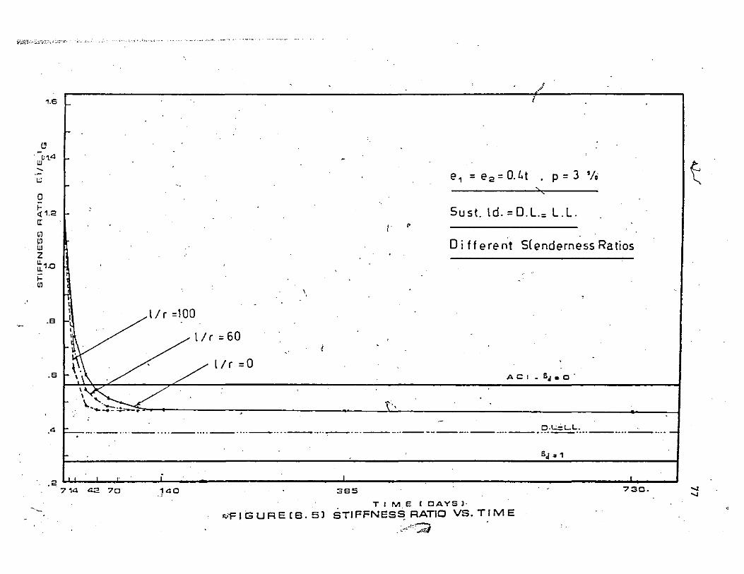
;irnt '.-;'l.'","" ,~~:~':,,-. , .,' 'M, ~"
1.
II UJ(;Vl , u;
o f-<t 1.2 rr ,) ,~
W Z ~1.o <-til
.8
.8
."
.2
~-
r i
-
- -e 1 = e 2 = 0.1. t . P = 3 'I; - -- > c
, Sust.ld.=D.L.= L.L.
I • Different Slenderness Ratios
-\ ,
-I l/r =100 r! I .
~1/'"60 \
i .
.
r- \,. ,\ . ' '/ l/r =0 A C I • 5 ... 0 .
r\~ " ..... ~~ .. t,
-, -~-.. -- .... -- .... -- .... -- .... - .... -- .... .,.---, ... ---.. -------.. -- .... --.~:~: .. --.... -. _ .... -
SJ 2 1
, . , ,. . i , .1
o 385 730.
. T 1 M.e (CAYS]'
"'FIGURECB.5l STIFFNES~RAnO VB.TIME .>·--!~·A
I
i
~
... ...
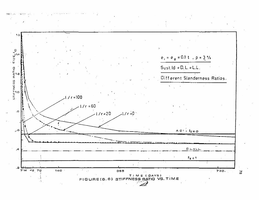
o ~1
I:J , I:J
a ;-<! 1. II C1 ,1 U Z ~1.0 f-~j
.0
;
,
~
,
, ~
. . '.
.
,
~ I I r =100 '.
\ ' ,>-, " "'./ I I Ir=2D
0 ~
e = e = 0.1 t , 2 • p = ~ 'I,
Sust.ld =D.L. =L.L.
Diff erent Slenderness Ratios. -
,
.
.
I I r ~D . . \,UI/c.60
~//' " ;X' ~ '.' \ '
.. -.c.~ A C' - 3.J=O ,..s
A
. 2
\'. -'-..... . ---. - '-. -
f- ' C.L.." L.L. 1-- .. ,-.... - .... - ... ~ .... - ... _ .... - .... _ .... _ .... -. --.-.... - .... --,-.... - .... - .... - .... -.----
"
f-,
I • , 7 ... .4 L2 70 140
\ l
.'
365
T J M E [ OAYS 1
FIGURECS.S) STIFFNESS RATIO VS.TIME ":;d''''~. . ' - .
"~ ~
Sl = 1
730. ..... co

;;:i;':j~'-:, ,;':-i~l,.·~-. .:,. ....
1.6
II
11,p1.4
,
'" o f<l;'.2 cr Ul Ul uJ Z ~1.o f-Ul
.S
"
I I I I
I I
I ~ \ \ I
~
\ . ,
0.$
e 1 = e 2 = OJ t , p = 3 'I.
Sus!. Id.=0.7Ult.ld. 't.
Oi f fer ent Slenderness Ratios.
I Ir =100
,
'" r( ,. I/r=60
. I I r =0
AC' •• ,:0 • __ ~ ~. -- --.---L.. - 1....L...
• --- o .. -uu
.0 \ ~--'7~c-- ... ~ ~. ' ...... -.~. .~. -.~ ',-," -._, ........ _-
6,=', .' I i
, ! 1 ~, I .... _.
.2 . 714 0::2 70 , "0 :365
TIME\COAYSl
FIGUREC·S.7l STIFFNESS RATIQ VS.TIME
.----1
7:30, .... -=
-<J
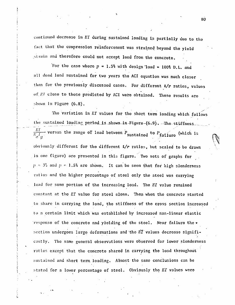
I . 80
"Ollt lllllod docroll3o in E'l during sU:ltninod lOlldins 1:1 pnrtililly <luo to tho
raLl thnt tho comprossion ro'inforcomont WIIS strlli.nod boyond tho yiold
."l ra in IIlId thoro foro could not nccopt lond from tho concroto.
'I'or tho cnso whoro p .. 1.5% wi th dosign '"lond .. 100!!; IJ. L. nnd
nIL <lolld 10lld 5U5 tninod for two yours tho ACI oqulltion wus much closor
t.hall for tho proviously discus!lod casos. For difforont 1/'1' ratios, vuluos
of. I..., clO:lO to thoso prodictod by ACI liOro obtainod. Thoso rosults aro
/' '1110 vnrintion in /','I valuos for tho short torm londing which follows
t ho :;u~ till nod loud i nG poriod .. is.!lhown.in .. Figuro ·(6. 9). --TI10· '>tl..ffn05!L ..
Kf . ','-J- vorsus tho ranr,o of loud botlioon P tid " • sus II no
" f}
to P i'aii~ro (which 15
ohv i OilS ly di fforon t for tho di fforont 1/'1' ratio:', but scalod to bo drawn
ill ono flr-uro) IIro prosonted in this figuro. Two sots of graphs for
l' " 3t lind l' " 1,5% nro shown. It can bo seon that for hish slondernoss
rnt io:; lind tho highor porcontngo of stool only tho stool WnS currying
load for somo portion of tho incroasing load. Tho E'I valuo romainod
con:;tant at tho I::I valuo for steol alono. Thon whon tho concreto started
to share in carrying the lond, tho stiffnoss of tho cross soction increasod
to a certain limit which wns establishod by incroasod non-linear olustic
'responso of the concroto and y}olding of tho stool. Ncar fniluro tho ..
''''ctlon undergoos lnrgo deformations nild "tho i1 valuos docrenso signifi
cant I y, Tho sarno gonoral obsorvations woro obsorvod for lower ~lendernoss
rat ios except that tho concroto sharod in carrying tho load throughout
sustained and short term londing, Almost· tho same conclusions can bo
stated for a 10lier porcontngo of stool. Obviously tho EI values wero
..
c~ ,

--~,,:-:; ;~.----." . '-- ..
'.4
'.2 !
.
.J '.0 , .
3 .9
.9
. 4
.
_0> .
u w .... -W .
' .
/'1':100 '~. LL/'<60 ",;0 ~" - 'L' ,\~ :/-' ....
"" ' ~ .
" .. ,-- -.~ , .. _.
1 .
e,.= e 2 =O.4t ; p =1.5 'I, .'
Sust. >d-. = fun Ol. .
Oi fferent Slenderness Ratios. .
,
.-----! .
ACI._ &.1.0 ,
, . O.L: LL - - --~- - - --, -"J
........ ---.--~---.----~-,-- .. -~----------:-----.-- --------------------- -- ---- -----------'.2 S".1
,
. _f. f L
o 71442-70 ,40 395 TIME.COAYSl 730
FIGURE(6.81 STIFFNESS RATICJVS:.TIME • . '--' ..z';/ -----:;:",.. ...
i
'" ...

i !
, ,
.i , ,
.i ,
"
"
.0
m l/r =100 ,p"3°lo
UI
'" " 0
> <t IT
In UI
'" z II II ,. U1
"
.n
.<1
.CJ
--
,.
....r .- ~ -
" \ /0·~~=3.:tL. -' .' -. -' .' ........ ->. . .--' 0 " ....-- ---- --.----.-~!.;..~--.~~-=]~~-.-- \. .......... ...-.
...... .,. _ ..........
_ .... ,.. ........... ,
l/r =100,P=1,S°/. '. , , . ..:-- .. . --~---.. ~ .. - ........ '\ . .....-' -·~-r/r =60 ,p::l.S I. .,. __. c. ,
.;....:-. l/r= 0 ,P=l.So;. - -- ... - ---------- -- - ... --- - - ...... .... ----_ ...... -- .... -_... ... ..... ------ ~
----- ---
Ol-i--\ __ "_----.;1
'\
~\UDTAINEO P FAILURE
FIGURE (6. 9) STIFFNESS RATIOS VS.
SORT TERM LOADING TO FAILURE AFTEf:! 2-YEARS
qF FULL o.L. SUSTAINED.

,.,
" alHays lOHer than those' fer p a 3%' because the increased amount of steel
in the first set gives morc stiffness to the section through out the
process of loading to failuro.
83
In summary it can be said that the ACI dosign is most conservative
for high £/r'ratios.' Since sustained load and column slenderness have
little effect on the capacity of column sections or short' columns, tho -.
satisfactery results for these cases do not provide any argument for "
\ C).-,J ,accepting the ACI ~loment Magnifier Method.
': "
6.4 SERIES (8), STUDY OF THE EFFECTS OF VARYING THE LEVEL OF SUSTAINED
LOAD: , '
To study the effect ef the level of sustained load and to measure
the accuracy of the ACI equations for handling th!,! effects 'of the inelas
tic:deformations, different levels of sustained loads Here studied. The
I short term capacity of each column was dctermin~d.· This only has meaning
if live loa'd l.s 100% of the 'total loading. , '. " v
THo cases' lihich are more'
realistic (Dead Load a Live Load and Dead Load a 100% oLthe total load) ,
:1 were analysed to find the effect of sustaining the dead 'load. The re--t:
; T.
maining capacitics nf~e;r, sustained loading were also determined. , Finally
analyses licre performed ,for the' case of Dead Load = 10.0% of the total load'
and- with the ultimate dend load of 1.4 D.L. being sustained.
6,4.1 'CO~WARISON OF SAFETY FACTORS .
Table (6.2) contains the safety factors calculated for the four
above mentioned loading conditions and evaluated at the different ratios _
of i/r and different ,end eccentricities. It can be easily concluded from
this table that the ACI! s method, is most conservativc for hig':-levels of
sustained loading and for high slenderness ratios. The ACI design method'
I

84
:-;"
.. 1'S much more consistent, for low and moderate sIc' d ' i " n emess rat os'. ,TheIomp~ted
safety factors increase with increase 'in the level of sustai~ed load for , ,
high i/r ratios, For s(;ctions and short'~olumns the safety factor ~e-",
creases with increase in the fevel of sustained load. This latter aspect
results from igno~ing the effects of seconnary moment (P.~) for short
columns. The results in Table (6.2) indicate the inconsistency of the
, " (2) safety factors ,obtained according to the ACI Standard 318-71 •
The ACI method is still very conservative for high slenderness
'ratios even for unrealistic case where the'Dead load = 100% of the total
load and the sustained ,load = the ultimate design dead load = 1:4 Dead-
load.
Figure (6.10) was drmin tq indicate the accuracy of the ACI values I
of EI for different' lev~ls of sus~ained loading. For e = 0.4t and p = 3% I
'and 1.5% the, computed 'values of EriE I fbr different combinations of , c g
loading are shown along with the ACI values. Computed values are shown
for the following cases:
(a) initial application 'of the design load"
(b) after two years ~f sustaiped dead load,
(c) at failure as tke load was increased aftar the period of ,
sustained loading. • >
The' computed Et values after su~ained load 'are slightly higher,
than the ACI valul's. As more load is appli!ld to determine failure, the
concrete again begins ,to carry a greater share of the load and the computed r
EI values show large increases. Even as the failure load is re'ached the \
EI values remiaQ higher than they were at ~he sustained load stage. , The
, ,
l.

"
"
)
1.6'
1.2
-1:1 .8
.c..
a
U1 II o Io <t3 IL
> I-
-1:1 C.
< " 2
.1 (
__ ACI-EQr : ___ -INITIA(.·, _~~ER2-YEARS,
-·-AT FAIL_ --------- r -_ :!"3",_ - .... - - ------:-------- --..: f- _-_I.:..'~",o
. '
---- :;------
~~--~~3-"Io
~ ... ~. - -~---
-~---.:. ~.----
-... ., ---.:-
\\ 5"10
L. D. = l,.. O. lAD. LEVEL OF LOAO.
Fij:ure (6.10)
: Compariso? of EI ~lues (e1'~ 6 2 = 0.4t,
P sust. =D. L., l/r .=' 60)
... ' " " " .
-" [.-' ./' , .
I
'3'" ;"~/
, ~~ .. ; :/, '-- ~::;> .... \ r:> : . ,. .I -~. - ~~--::..:::.- ... ACI_S .F.·
,
, I I· I
I I I I I
. ! i
" ,e ,= e 2 = O.l h. ' SUS ained k ed=fu lO.
i- ,
I
I I \ '
I a
a 20 40 Gal BO Ir 100·
Figure (6.11)
Inf1~ence'of p on safety (D=100t, L=O) ..
85
,
\ '
-'l I
/
..
j , i
" ,: , ; : 1 \ j
-r ."j I
I •
. , .. 86) ,
I
same trend Has '<Y,~,"",-ed for po l.5't and p = 3%. ~As is expocted the EI .. valtles decrease ~s the of sustained load increases.
In summary u'n:ru'e said that the ACI equations for determi'na-, tion of EI for the different evels 'of sustained loading ar~ not consistent.
'The computed failuro' s are (in most cases) muen higher than'theACI
fa,ilure load. ' Thus the comparisons betHeen EI values computed at failure
and th~, ACI, va1ues do not show the even greater difference (Iihich could be
considered significant) which exist.: When' Ei values compu'tcd at th'e'level
l
. .. ,'" ~ . ' ,
of Ai:I prer.!icted, failure load are compared with ,thOSe of the ACI much mo'ro
inconsisfency is observed. The same arguments disctissed for the momen!= ---magnification phenomen:l.,lihown in Figure (1).3) apply her~.
, " ,/ The influence oJ EI in the design process will be disi::,ussed in
(
Chaptet (7). "
6.5 SERIES (Cl, STUDY OF THE EFFECTS OF VARYING THE RATIO OF STEEL
REINFORCEMENT IN A CROSS SECTION:
Only two ~ifferent steel ratios [p -
= '(A +A' )/bt] were chos,en to 8 B
,represent the range of reinfor~ement ratios in normal desi~n c~es. The ri.
tHO ratios.w~re chosen to be 1.5% 'and 3%. ~!ost of the ,cases' studied were
f -~ orp = ,:>-0. To demonstrate the effect of steel in slender columns, the •
case Hh,ere dead load = 100% of. the ~otal load and e = O.4t w'as studi:6d for
p =' 1.5% knd different' slenderne~sratios. ' Table (6.3-) contains the re-I
suIts. The variation of the safety factors for d~fferent steel ratios , -is illustrated in Figure (6.-il).
• In this Figure the safety factors for
p = 3% shoH the same trend -of, increasing wit),' increase of slenderness
ratio. It is also clear from this figure that the ACI design method is
more accurate for Jo~r steel percentage, but it'i~ still very ~onservativir.7
.i . '
" ----

87 . I • ,
"
. ,
'- , ~ "
. P R./r I P : App1.1d. I Actual . UAG1 U .
~ comp F.S.
, 0 186 j 192 93 2.06 . .
• , . . ,
20 186 '. 190.5 93 {/ . . L 2.04 • \
" . . 40 136 . 153.8 68 , 2.26 . '
. (
~ 122.5 " • 60 97 48.5 2.51 . , . i
, 0 .
80 .. 14.4 107.8' 37.2 0, 2.92 . , . ,
100 49,2 91.0 24:6 ..
3.68' • "- ,
• \ , , , . ...
, l Table (6.3) • Comparison of Comput~d Safety Factors
. ~ , -for
, . , Columns Designed by ACI '418-71(2).
(M1 = M p~ 1.5%, f' = 4.0 ksi, fy ,.. 50.9 kaf.) 2' .. c
L = 0, D = 100%, P = D sust.
"
\
. , '( c 7 "-
1
·r.

f
i i
t
I
l-
,
... ~ , d' "
r , 88
~
\
The same discu~sion for the variation of EI With time and lIith the "
level of sustained loading <;an beqis'cussed here also. Figur!l (6.8) is for
'" EIIE I versus the duration of sustained ioading. c g Th~ computed iI valu~s . ., ,..,.
• arc closer to the ACI values than lias the case for p ": 3%,. Als<l> from , .---
Figure '(6.9) it can be seen that the behaviour of EI for th6 different
column lengths maintained the same trend IIhic~ w~s ,discussed previously'
for p = 3%,. , . .
In conclusion, the ACI equations performed J).etter in lOller steel - \ \~;
'" ratios. This may mean that the ACI equations underestimate t~ effects
~f steel. HOllever even at such 1011 values as for p = 1.5% the ACI
equations yield very conservative solutions for high'slenderness ratios. . '
/ . SERIES (D), STUDY OF THE'EFF~CTS OF VARYING THE.INITIAl,END
ECCENTRICITIES:'~ , ,,:, -, ,
6.6
- J Individual columns \lith slenderness ratios,'9-/r, from 0 to ~OO
liere analysed for various' combinations of end eccentricities and Idt'll, ~ - . .,..
t~e previously discussed different ~ustained loading levels. Th~ eccen~
tricities used in the investigation are O.lt, O.4t and balanced'eccentri-
city, e bal.
Table (6.2) and -Figures (6.1) and (6.2) show the'v~ri~t'ion of
safety factors ~or different eccentricities. For all values of slender
ness ratio arid ~11 combinations of load, the safety fay tors w,ere, always
largest for the smallest end ecc~ntricity (which lias O.lt in this study).
Less inconsistent safety factors, ~ere obtained for the other ~IIO eccen
tricities of O.~t and ~~al. An explanation for this behaviour is dis- r cus~ed in the conclusions in Chapter (7). "
I,n Figure (6.12), (6.13) and (6.14), values for EI/EcIg are plotted
r

, , '
89
versuS duration of' susta~ned loading., In'each figure a set of graphs for
~ par:icular level 'of sustained load, ona slenderness rat;io and different'
end eccentricities is shown. •
In Figure (6 .12i, ~/r = 0, p c 3%, D.L. c L.L. and the sustained , '
load is the ~ead load portion. For e = 0.4t and eb 1 ' the E~ values a • . " " ' al1proached a constant value which was found to be the EI value, for steel,
alone, ,\'IiH~reas' foX: e = O~the c~>ncrete shared' ~n carrying the load and ,
,E1 maintained higher values. The factt, 'that the entire 'section remained
, in compression for e = O.lt 'may ~lso be an important differenc!l.
In Figure, (6,.13) ~-d (6.14) where i/r '= 60 'and 100 respectively, .... ' /;
'the EI'values:approached the constant val':1e for ~t:eel stiffness for' all
the tlJree eq:entricities,. The time required for the' flexural stiffness , '-
to reach the constant value was longer for smaller eccentricities.
In summary it has been demonstrated that the ACI is most con
servative for'the cases ~of small eccentricity, for all values of sienderness_ • '. I . .... .
ratios and all levels of sustained loading.
6.7 SERI,ES (El. srUDY OF THE EFFECTS 'oF VARYING THE RATIO BETWEEN THE
TWO END EGCENTRICITIES: I
This series was performed to study, the degree of accuracy of
the ACI formula;
"
Hhich takes into account the' effects .of unequal, moments.
,.
A moder2:te slenderness ratio- (f./r=60) Has chos~n to te~t this
equation. The loading chosen Has dead i~ad = total load. One of t;~e end
J
eccentricitipj, e Z' was kept constant at-0.4t. The other end eccentricity, ~
"
\ : 'r '

~;:.-.- -"",-,~",."..,~:c;-~!..:~ ... _-" .. .::._~!,,-:~,-\..,.,,",,,,,-.. -,,,.,,--...,. .. ".....,-=,-~ .. ~"~""",_""",--""""""._"'_~~~~~' __ T.,,,_~'
1.G i
~
'WD1•4 , - II w· 0 f-<t 1.2 II III III w Z 11. 11.1.0
i= III
- .8
t .8 ,
',4 ,
.2
./
,1. i' ~
e :0.1 t
~
e =0:4t .;
• ') ~ '----- "j
~ -...........
I / r = 0, p = 3 '/,
D.L.= l'.L .. •
• Di ffe renLE cc e nt.
>
.!'
e = ebal. .,
ACI_~.O
\"\..'- - , ............. --... ,,'
~~~""'-'--''--'---'---'---.~. ---<t. ____ • ___ • ___ • _. ___ • ___ • ___ • __ ~ ___ _
" "" 01 .. : L.L. •••• ___ .... ,_ •••• _ •••• ___ .... ___ •••• _ .. t •• ___ •••• ___ •••• ___ •••• ____ •••• ___ •••• ___ •••• ___ •••• _ •••• ___ •••• ___ ••••
B,,:1
, 714 42 70 140 386 ..... 730.
T r Me', OAval
. F I C3 U ~ E (·s .1e) STI FFNEBB RATIO VB, T IIY1 E
\0 o
I.
(

,
' I 91 , .
, . I .. I a i
,(')
. I " .J..
a J:
~i ~
II " , ",-' ~
.J, °1 "'-
U r ...:: 'ot a,
M
I " .-- C 0. ClI i w u
I ~ u
W .. i I -/
0 ...i . .-. ( lD - I .' ,/ ·C .J <U ~m'
, II
: I L..
'm> / II <U
I L.. - >-0 ...... ;.J -. j <t._ 0 0
\
I ~~ , \ wit
i ~~ ~ {) -w
I 1-2 I LL
I) LL i m l-I (') m , ,
~
'\::"'.-' I (I) '<" - I III i m ..0
I ~
ClI w · II
I l It ClI I :J
(!) - I -:r I LL . 0
· 1 , I I \ ,
· , a
1 I II .. ,
I
I "
J I a " , ru II ... --. -~- .
-~~-~ II .. ,~ --- ---==-- -" In \I. ru Q m m II, UI r .. ,.,
!O) 1"'3/.3 ..
OI.L"'~l SS3NoIoIl..I.S
j ,

~+-'",:::::::,"~::::;'~,.::..",'",,",:'- _,;'~'~'t: ... . ,. __ .~",.-,,;. .• ~.:v..~.i .... ::~>_":".i,.:. __ -;";':'::"'''''''''-______ ~:'':'''-:''_''''''''.O'''''''''-''_~' ..,...--..... -.".---..- ...... ..-.-. •• -.-~~-~--~ -- .• _--
1.8
(!)
J1.4 .... w
o
"-. \. •
• . ( . . ~ .. ' ,
,V:' ~J
q ,
• _, ~ - I
I- '".' ' " ~ l /r =100.p=3"1a '
,I. -, D.L.=l.L. ..-f<1:1.2
! .
I '. '. Different Ecceny , _ I , 0
a: UJ UJ
I e=O.1t··, , . I . ' . ~ 0 •
I • I e =0.4 t ,,~
~I ", _ ' . v.
w 2 ~1.o
~
~r :' e=.eb·al. :\ •• ' • _, 0 C
-Ii . r ' .. ~', . . I- \ . . 1\ . • - ,\ A C I ~ B.= 0
,8
.8
~\ ~.
-\' - .
••.. ... ~ { • ! •
~ .... _ .... _ .... _ ..... ..:.-:. .... _ .... _ .... __ .... _.... • •• 0 O.L."L.L.' ,'_ _ .... -=-- .... _ .... - ..... - .... _ .... -,_ .... _ .... _ .... - .... ------,------,4
~ . . . . .. _ • . B. :: 1
~ . . ,2 .. ..
714 <la 70 140 :386 7:;J0 ..
TIM E , OAV8 I
F I C3 U R E (a .14] aTI FFNESS 'RATIO VS. TIM E (
'---
/; -
'D N
•
'0

j i !
I \ j
i I 1 I
! \
I
, . . , 93
"
°1
, Hasgivon the following'values: .
. . ~ O.lt, ?4t, '(lba1." . '. '" ~O.lt,.-O,4t, -ebal •
# '.'
The same procedure. as was :descriged earli~r for ev~luating th~' saf~y , , .
f>actors was usep,.here. Tab~,e (6.4) 'shews the .results of this sel7ies •
. ,'Th~ s~fety factors exceeded ~h~' AC:! nomil'ml safety factor'by amounts
ransed from 12%. t: 32%.,' Thereio,re ~'was concl~ded that the pio;ed~e : . , '
'/
•
· " . -which' i~. llsedto account for.' unequal~ end eccentricities is not a major
· '. . oJ • source or inconsistency for safety of. indivi!:1ual isolated columns. !\.- .' I
6. 8 ~SERIES (F), STUDY OF THE BEHAVIOUR OF COLUMNS AS PART OF A STRUCTURE : . '" ...
, 10 study the. \>ehB:viour of the' column as' part of a structure two "
'multistory frames were analysed. figure. (6.ts.c) sh,ows the mu~tistory-
multibay frame analysed in t~is study. One of tne interior columns label-•
led (1,. 2 and 3) was analysed along with an exte:i:'~or co1wnn for the 10ad-\' ,
ing'case shown. The dimensfons of the ftame are shown in'Figure (6.15.c). , ,,"'to; .
\lsing ACI 318-71 the nominal 'safety factor£or column (1) is 2.31.' The,
computed safety factor is 3.15.' For ,the exterior column the difference
Has not
reserve
as the
•
, as large. Since these columns had low slende:rness :&tios the
strength is partially due to ~~e reduction 'in~men~ Whi~'occurs cOlumn~becomes more flexible.
In figure (6.1s.a) the reiationships 'j
between the axial 103.!i and
maximum moment on columns (1) and (2) are shown as the loads are in-
creased up to failure of column, (1). The slight detrease in capacity
Hhich should result from the magnified moment (P6) is cqmpensated for by
'the reduced dist~ibution ot: moment to the columns. .Th;, changes iri EI l .
during sustaihed loading and as the loads are increased to failure are
/
•
,J
". "
•
•

I
1 J
1 , ! !
l 1
, , /,
ci
O.lt
• 0.4t
chal
-O.lt
-0.4t
-cbal
94
.
.... 8 2 p P .
App1.1d Actual M 'M Mfail M uAC1 u' F.S. ' 1 2 uAC1 , comp,
OAt 175 230.5 87.5 . 2.64 87.5 350 '972 983 )
i
, 0.4t 1,51 196 75.0 2.54 300 300 1100 975
/" . 0.4t ,'126 163 63 2.58 252 ~ 355 1121 1000 .
, ,
0.4t 200 235 10q 2.35 -100 400 1016 945 "
-:::, .
OAt 215 '263 107.5 2.44 -427 427 893, 900 /
. 0.4t 19Q 212 95.0 2.23 -53!! 380 1044 960 '
• Table (6.4) Compari'son of Computed Safety Factors for
•
, ,
,Columns Designed by ACI 318-71(2) (p = 3%, , ,
f = 4.0kai; f = 50kai, 1/r = 60, L = 0, , c y ,
D = 100%, P t = D.) For different Ratios sus. .
of 8 1 to 8 2, ACI's F,'S, = i.oo
,
",
•
, '"

__ v_._~ __
-C' 0"'-
/
,
~
-<",
I. ;
1.2
~
,D ~u ... C!. .8
.4
·0
.
e
" .................. '.
~ '\ ····._C PMPUT a . \ '" ~ ... .. IN~~R i~ll~.N ", IA
. ", ~ .... ~. \
COL,lll: I " IY,I I
TER_ ........, / ,. / . AC ION
/-" \\' A.GRAM ,/
" .r.-CO .121' , . I~/ (
1/ /
47 - S!L~.ta. ':"ned L a.y .-.-- - - - ------
. 05 .10 .15 .20 .25 , M IP~~ t 2
" (a) Column'-Load History
a. L a ONLY .
J 0 ONL~ O'L' I ~.- _. EI j- ..... _-_ ..... _ ... _.-_._- .. ----_ .. _----_.
....... _ .. _ ..r~_~_- ........ ,. __ ___ .. _·r- ...... -.. -~ ______ . I i ~=~. I
l ......... ~:_l:_~Clg,,!!:-~ __ ~·~_~~_ .~~_ .... l .:jl I ... I"·-~'::; EI
EI . ,
I 1.7 l .j 1.7l 1.7l ,.1.7l 1.7l
(c) Actual Frame
,.
I.
m . w" ... --
,
!
, "
I~ ., , ., j:
•
"
1\ 3 1\
UJ .8
.il " .... , : " ~, .-=-..=-.-
l A
a
COU2l .Jo ..... - ... ,
/--. • .'/ ' \: " \
I .'. \ - ... ), : I
I I COLli}, , -, ; \ , , : \
.1J - \ \
~-:;. \
~ , .".
. I ToOs CJ T.2YRS .
UST _·La. . FAILURE
(b) Variation in EI
11:6 L :: 20 EJ p~:: D+D.2L n , EI7EI l/r.''7. 58
q~ Pt= 3%
.-
;;
. (d) Equivalent Frame
• Fig. (6·,15) EXAMPLE OF BEHAVIOUR OF COLlJl.lNS IN . FRAMED STRUCTIJRES
•
,.
f
\0 V1
'--.

I \
i r , I i , , I ,I
i 1 I
"
l
J i I ,!
J
• 96
" .. '
, shm;n in Figuro' (6.1S.b). ,
Creep and'sh'rinkago of' tho concrete, after application of axial /,
load and bending moment cause the 'columns to lQ,oso much of their' stiff
'nessss du~ing the p,o;~o'\. of sustained £'bading. ' Similarly the inelastic I • .
, ' ,
behaviour of the 'con~;retll and steel has the same effect during the late , "
stages of short term loading to failurt::. Consequent~y for both cases a
marked redistribution of bending mOjllent occurs lihere most' of the 'moment is Ie.." ,
'transfered to .the f;oor Jembers. , ~Iaterial ~aill1re was established for
all, case~ studl.ed., Column, (1) failed first for both cases, 'for column (2)
For the interipr column (2) was in double curvature in ,the exterior "frame. "
the axial load on this column was substiI\tially less ihm;, that fo'r ,column
tl) .
The analysis of this frame and otHers which were braced against'
sidesliay or liere not .much affected by horizontal load leads to the " . general conclusion that failure 'due to instabili'ty co~ld ra},ely olccur if
I at all. The effo.ct of moment redistribution 'as col=ns become'less stiff
and the fact that very slender columns are rarely found in practice are ,- .... . "
ar'guements in support of this statement. ' " 1
6,9 SlJl.1I-IARY
In this chapter the analytical results were presented and discus
~ed. It waS generally concluded from these anaiyses that the ACI 318-71 (2)
noment magnification method is IIiost conservative, for high iiI' ratios, low
eft and high sustai'ned loads. Even for the unrealistic case'of sustain-, ,
ing 1.4 Dead load where live load = 0, tne safety is not affected much. 'G'
Reasons for the above mentioned trends, final conclusions, some ,
recommendations and some constructive suggestions for the improvement of
the design method are given in Chapter (7)., n

CHAPTER VII
CONCLUSIONS
7.1' SUMMARY OF THE STUDY
The main purpose of the study reported in this thesis waS to pro
vide a basis for the evaluation of current design procedures-,for re.inforced
concrete columns. ,The specific area of interest was to measure the ac
curacy of the ACI 318-71 (2)' equations for designing slender columns ..
The effect of column slenderness, which is fUrther complicated by J
consideration of'creep under sustained load, was the main topic discussed'
in this thesis. It was suggested that a realistic appraisal of design
methods must be based on the idea ·of consistent safety factors. Thus ~
,,!;lendcr columns subjected}o sustained, load must retain sufficient reserve
capacity so that failure loads when compared to design J~ads provide equal
safety' facto s. Chapters (1) through (5) contain description for the
analysis used in this study. In Chapter (6) the anlilytical
resul swere comparisoned and discussed. In this chapter final conclusions
and recommendations are given. .. ,
(7.l.a) Design Parameters.
The magnitude and effect of the additional moments due to deflec-
tion should be detez:nuned for the full range and combinations of design
parameters .. Such a'comprehensive evaluation was not attempted in this , .
study. The values of design parameters chosen were selected to be repre~
scntative of normal design practice. Those parameters which were inc~uded
in this study were discussed in .'Chapter (6) in full details and are briefly
given below. , 97

• '98
(7.1. b) Column Properties.
For simplicity 9finterpretation square cross sections,with
'symmetric r.einforcing in exterior layers. w.ere analysed. "The reinforcement . ,
wits positioned so' that the distance, (J, beb/een tile ext\lrior layers was
O.St. Most of the results prc;;ented were for p = 3.0% although some , results of p = 1.S% of steel were provided for'comparison. The concrete~
\
str,ength used ~as f~ = 4.0ksi and steel yield stress is fy "SO.Oksi. No
increases of c6'ncrete strength or modulus of elasticity were taken into
account. The prop~rties of concrete were based on test res~lts(lO) for a
particular concrete which was specifically designed to have a lower than , '--"
average aggregate to cement' ratio and therefore a higher ·than average creep
and shrinkage. The compressive failure strain was taken'as 0.0038, and the
tensile strength of concrete was disregarded.
Individual columns with slenderness ratios, 1/r, from 0 to 100
i;ere analysed for various combinations of end eccentricities. Also' an
example of the behaviour' of columns in frames lias, presented.
(7. I.c) Loading Conditions.
The'columns analysed were designed in accrodance with ACI 318-71(2)
where, in addition to knoJing, the section properties, the 'values of end
moments, the effective length and the level of sustained load were required.
For the analyses of individual cOluhtns (k=l.O) ,e lIlajority of results
were for the case of symmetric single curvature where the effect of Pll.
is largest. Several cases of double curvature columns were also studied,
The ecce,,' -ici ties, used in this investigation ,,:ere O.lt, 0.4t and balanced
eccentricity, ebal
•

99
, The short term capacity of each column was. dete:rnuned. This only
has meaning if Live load, L.L., is 100% of the total loading. Two cases
which are more realistic (D.L. = L.L. and D.L. '; 100% of the total load) . .
werc analysed to find the effect of sustaining the dead load. The re-
maining capacities aftefsustained loading w~re a"l~o determined. Fin~lly
analyses liere performed for the ca~e of D.L. =' 100% of the total·load and
with the ,ultimate'dead load of 1.4 x D.L. being,s~tained. For this study
sustained ~oad waslIlaintained for only r years. Previous analYs:s (10) I •
have ShOlffl that most of the effects of creep and shrinkage will have'
occurred during this time. This is becaus~ the rate 'of creep is'ne/lrly , . ,
proportional to the logarithm of ti~e and becaus~ the stresses in the con~ ~ . .
crete decrease as the reinforcement carries a larger share of. the load.
Details of the abo~e men~ried anroryses are included in Chapter (6)~ \ .' (7.l.d) Method of Analysis.
A compute~ program has been developed, to predict the behaviour '.
and capacity of reinforced concrete frame structures. Details of the
major features of the method of analysis have been report~a in Chapte,r (5).
The accuracy of this method' has been verified by·the comparison(10,U,31) . . of the analytical results with tests of 'colUmns and frames subjected,to
, t . A very brief description of the method . ' short term and sustained "loading.
of analysis is provided in.the· next three paragraphs.
The response of cross sections to axial load and moment is found
by dividing the section into strips. For any plane distribution of strain I
the stress on each strip is calculated taking into account the amount of
creep and shrinkage which has occurred at the centre of each strip. The
sum of the forces and the moments' of the forces from each. cross section
strip and from the reinforcing steel are, compared to the applied axial
" , (
, '

r
- .. 100
1,.
load and moment. Tho magnitude and slope of the plane strain distribution : I
arc varied until the internal forces 'balance ,the applied forces. Failure , ..
~<
of the cross section is defined lihen the internal forces cannot be in-
creased to balance the applied forces.
The straj,n distributions for equi;ibrium of internal and applied •
forces, provide values of equivalent stiffnesses (EI = M/~ and EA = PIc. . ) . ' ax~al
which can be used in the elastic structural analysis of a column or, frame.
In 'this analysis the members we~e·divided into short elements. 'These "
clements. ,are assigned stiffnesses. which arO' the average of those calculated
for the cross sections at each end. USing a matrix analysis fo~at the
forces and displacements at the ends of each elem~n~ are computed. For
the axial load and moment (including the P~ effect.CalCUlated using to 'displacement information) at, 'the ends of each' element the new stiffnesses "" .. .'
arc found and compared to the previous values. Using'an iterative process
for changing the stiffnesses of each element, convergence for equilibrium
,'and compatible displacements is achieved when all calculfed values of
stiffness coincide with the'values used in the previous Jttuctural analysis.. . ~ --.
, . For sustained load the magnitude of c~eep ~d shrinkage are cal
c41ated and accumulated'at regular intervais. The externally applied
loads may change accordirlg to any predetermined pattern. Usu~lly a period, . . . I
of constant sustained load is followed by short term loading to'failure.' "J> . ~Iaterial failure is defined as before and instability is identified when
the stiffness values for a particular element do n?t converge •
. 7.2 FINAL CONCLUSIONS:
The fact that ~lenderness and sustained load decrease column
capacity is well doclli~ented(lO,al). The results of this study indicate . ,
•
.'
, '

101
that the provisions of ACI 318-71(2) to account for there off;cts do not &
result in consistent safety factors. As was discussed in Chapter (6) the
ACI method I~as most conservative for high slenderness r~tios. small ec-
centriSit{es. and high levels 'of sustained loading. , ,~ /
Using thiS, accepted
desipn method aS,a basis for comparison. several aspects of the dJsign
are identified for consideration.
1. For some cases where the effe,cts of~ sustained loading of frames were /,
studied. the axial load was of much 'greater effect than the bending
moment sin;;ihe eccent;icity (,was initiaU; sm11. l'/hen the short
t~rm'loading is ~pplied (after two years of sustaining the dead load , .,
'portion of the service load) the capacity of the column varies depend-
ing upon the amount of creep and shrinkage which bas occurred regardless , -
of lihether it is due to axial load or moment. Therefore variation fn safety result.. This phenomena was mainly because the ACI equations
f . do not take the effect of sustaining the. axial dead ,load into account.
- ,
. Dead load Moment , .' In ,the ACI equations USl.ng Bd = Total load ~Ioment the effect of the
axial load is not included. In fact this could be of great signi
ficance in the quite c:ommon cases where bending moine~t is caused by , ..
live load and wind afte~ periods of sUstained ,axial load.
2. In determining the 'effective 'stiffness of the section the ACI reduces, \ ...J'
the stiffnflss of steel because of creep and shrinkage of concret:e. . .. . .
This reduction is questionable since th~ steel has shown to share
,u
effectively in carrying the load in all cas,es. Th~' effectiveness of [j)
steel was even more pronounced because of the creep and shrinkag~ of I. , .
f-.:J ] </>1:oncretc.
? \

'" 102 "
3. ,Duri~g sustained load the EI values tend to approach E I f~r any of " ,8 8
the following condition~; ,high t/l' ratio~ low ievel of sustained ,
load, large eccentricity to depth ratio (e/t), laI;,ge ratios of r~in-
.forcing steel (P), ,and for moderate combinations of these such as "
medium t/l' and p, or medium sus tainO!ld .load and elt. This behaviour
results. from the trans'er of stress to the steel as the concrete
creeps and shrinks. However, upon application of short term load to
determine failure, the EJ: values increase. It is suggested ~hat
sustained lo'ad as a percent of cross section capacity rather than
column capacity will provide a more realistic measure of the effect of,
sustained load.
4. The derivation of the moment magnirication formula is based,on the (
concept of including the PA effect when calculating the cross section
capacity required. However in "order ,to accommodate the possibility
o'f instability failure on' the basis of cross se,ction capacity it is
necessary to inflate the moment magnification values (increase PAl to . '
achieve the appropriate reduction in column strength. Since a common ,
EI is used for both material and instability failure. the added,
moment (PA) for ,cases with material failure is too large. This study
shcMs th,af instabili ty ~ccurs only at small ectentrici ties and very /
high til',values. Very slender columns are rarely found in practice.
Also the possibility of lnstability failure exists only at the slend-f' ~
erness limit, specified by ACI. Therefore designers :'should use the EI
whiCh produces the correct deflection rather than artificial value to
accommodate prediction 'of failure due to instability> -"- ,/
. , ,
' ..
•
. .

. 103
, I
5, Tho moments applied to columns in structures braced against. sidesway
ar~ limited to the moments transmitted by tho beams or slabs.' In . ., i
,many cases tho additional moments due. to deflection are largely offset . r .
by a~~distribution of the applied moment as the column deflects.
·[The stiffness of the a flexural melllber is not affected by deflection
and is not affected ~o the ,same extent by creep and shrinkage.] There
fore thera may be '>same benefit in us~ng diff~rent mo~ent magriifying
procedures depending on whether. or not ·the structurt1, is braced against
sidesway.
,.
J.
,
,' •. a
•
APPENDIX A
LISTING OF COMPtrrER PROGRAM
FOR
INELASTIC ANALYSIS OF REINFORCED CONCRETE •
FRAMES
I
I
104 -'. -

•
,
•
•
APPENDIX A
FORTRAN PROGRAM: INELASTIC ANALYSIS O:.;REINFORCED
CONCRETE FRAMES •
. Nomenclature.: , "-
The meanings of the variables named in the program ~e listed
below. Those that do not appear here bra defined by the context in
which they arc used or in the, f,\= of cOllDllant cards.
AASCcn
MST(I)
CF
CYL
DDB (I)
DDSC(I)
OOST(I)
DOrn(I)
EA(I)
EI(I)
ES
FXX (I)
FYY (1)
Fl-lM(l)
'0 .Area of compression reinforcing steel in member (I)
Area of tensile reinfOrcing steel in member (I)
Length conversion factor
Concrete cylinder strength at 28 days
Width of cross-section of element •. ~I)
Distance'from the centroid of the compjession steel to
the extreme compressive fibre of section of element (I)
Distance from the centroid of the tensile steel to the
extrem~ compressive fibre of secti~n of element (I)
Total "<iepth of cross section of element (I)
Axial stiffness EA for el~ment (I)
Flexural stiffness EI for element (I)
Modulus of elasticity of reinforcing steel
Applied load' in the x-direction at joint (I) ,
. Applied load in the y-direction at joint q)
Applied bending moment· at joint (I)
lOS
•
i
1 . , 'I
.,..: i : i I'j
~

,
FSY
NALLOW
NCYCL
NELEM •
NJOINT
NPLAST
NSTRJ.P
PIlI
PIIITRI
, PCAL. BMCAL
TJ,T2
WEEP,
WSHRINC
WTENSIL
Yield strength of steel
All~abl() cycles' of iteration for' subroutine "HPHI"
Number of allowable iterative cycles in main program , ,
Total number of ,elements in frame
Total number or joints' in frame
Total number of 'inelastic elements in frame
Numbe, of element strips in concrete cross section ,
... ' CUrvature'
"
Trial values for curvature , )
/
(
106
Calculated axial force and bending moment acting at' the'
centroid of'a concrete cross section
Time increment from time 1 to time 2
Creep strain :
Shrinkage of concrete !J
Allowable tensi.le strain of ,concrete
•
r
\ ,",'
{
-"
",

~t~' :JI:
iii', t?l' bC,Jr.':\
!1 I'J
1'[1
107 , .
1',1, VI I't ' ' 0
ij'lINISl /' . '~ r.n.L(·40000 •. ' "-~ A400 FND OF 'RFCORD '
i, ~~~~~~~:~=~-~:~~~~:~~~~~~:~~~:;:~~~~~:~~~:~=~~~~~~~~-----~------I)l ~~~~~~;-~~I~~~~SS'-~E;~~~-~~-I~E~~A~;IC-~~A~E-A~A~~SIS-------------'Q THES I S PROJECT • By S+SALLA", • GRADUATE STUDENT • J1 nFPARTMENT OF CIVIL ENGINEERING • MCMASTER UNIVERSITY , ii, ,W<1IL TON. ONTARIO. CANADA J.
!,a A JOINT IS CONSIDI:RED TO Ex,J.,ST AT EACH POINT OF LOAD APPLICATION ,1'1 A~n AT p.OINTS OF GEOMETRIC DISG:ONTINUITY. LOADS ARE PERMITTED l~ ONLY AT JOINTS AND ~UST BE DISCRETE VALUES (DISTRIBUTE6 LOADS ARE '~~ THUS RFPLACED BY EQUIVALENT SYSTEMS ~F DJSCRErE FORCES). ii(j ASSIGN JOINT NUMBERS TO ALL 'JOINTS' IN STRUCTURE. INCLUDING BOTH t! ACTUAL JOINTS IGEOMETRIC DISCO~TINUITIES) AND POINTS OF ;';(1 APPLY CA nON OF CONCENTRATED LOADS. ih ~LL LOADINGS IN THE PLANE OF THE FRAME (X,Y) ARE PERMITTED. :"'(~ FXCFPT TORSl0NAL MO~ENTS. ~g ASSIGN MEMBER NU~BERS TO ALL MEMBERS. MEMBER END 1 IS DE~1NED TO ~:;dl FIE THE END AT THE LOWER OF THE TWq JOINT NUMBERS WHICH Ud (OQRESrOND Tn THE,JOINTS CONNECTED flY THE MFMBER. 1;,lr1 \,LIVE = suPERI~POSED, LOAD IN KIP PER LINEAR FOOT ( It':rl (F=SCALE FACTOR OF LENGTH. IF IN •• CF=l.O. IF FT •• CF=I2.0
lua MFMTYP=! FOR PIN-PIN . ~IMEMTyp=2 FOR FIX-FIX
li,itl_ ~~7i~~ ~Lv~~~ I O~ ~ ~~: ~ ~ORCE VECTOR\ ~' ~~ TENSION POSITIVE ~t SHEAR POSITIVE CLOtKWISE lilt RENDING MOMENT POSITIVE IF TOP FIBRE IN CO",PRESSION ~~I DISPLACE~ENT VECTOR IN GLOBAL COORQINATE i!;j FORCE vECTOR IN MEMBER COORDINA.TE
it! I, ... :)'
l'.,!f, 1,: i':f
1]1,·1','· j I; I: [I
'1tl ,'l~ '1Jl ~'~, tl , '
_____________________________________________ 7 ________ -----------
----------------~------------------------------------------------, '
nI~FNSI0N DDTHll~0).DDBI150).AASTI150).AASCI150)'DDSTI150). 1 nDSCI!SO) , . ' nI~FNSION EIIlSO).EAI15 0 ).FAI150).FV{15 0 ).AMC{150 ) ~1~FNSInN EIIII20.30).EAAAI2 0 .30 )iTIJLEIIO).GII150) ~1~FNSInN FXXl(150).FYYlI150).FMM~(150) nl~~NSln~ WU'(?C.'C).UUF11?O.20).UUF'I'O.'0).fEI(~0) nlvFNSInN WFFPI20.?0).WUlI20.~O),CEEP(~O.tO).EEAI!0) ~1~~'ISInN WWW'I~O).PPH2130).WWP,(~0).PPHI2(~0) nl~FNSInN FYAIIOO). FMAIIOO).WWWl(30).PPHI(~p~.WWPlI30).~PHI~130) llI':ENSIONNEEI50ltEEAA(30) "
..
p,

• 108 (
,rnMM.nN/.RLCK1/NnllOO.~).Xll00).YllOO)'JNLI1~O)'JN~115O).MEMTYPI~~O) CO~~ON/BLCK2/NJOIN'NELEM,CF'NJL \', cO~~n~/RLCK3/JNNIIOO)'FXXIIOO)'FYYIIOO)~FMM(lOO) COMMON/BLCK5/AL(150),XMI150),YMI150).' CO~MONYRLOCKI/DTH.DB'AST,ASC.DST'DSC ' cn~~nN/ALOCK3/WSHRINS.~WSHRINC cn~"nN/RL()CK4/WTENSIL. WY,FSY, CYL, TCF, NALLOW, ES COMMON/BLnCK5/PHI~RI'WTRIAL
RE:ADIS,UOI ) TrrLE OJ, FORMAT 11 OA8)
READ CYLIND~R STRFNGTH , ST~EL YIELD STRESS, MODULUS OF EtASTICITY OF STEEL, TENSILE STRENGTH OF CONCRETE. JNITIAL SHRIKAGE ..
;, . ' . -------,---f:'--------------------------:----------------~--------- . . REA3~~';»CYL,FSY,ES,WTENSIL.. WSHRINC . I "
FOH\T13FI 0'o3.2FIOoO) - ,
READ'NUMBER OF JOINTS,NUMBER OF ELE~'ENTS'NUt~BER OF ELEMENT'S 'THAT NEEDS MODIFICATION FOR THEIR'STIFFNESSfS. SCALE FOR CONvERTIN~ ALL DIMENSION~ TO I~CHES=12.0 I~ THE FRAME'S ORDINATES ARE ~IVEN IN FT. ' , -------~-------------~--------~----------------------------------READI,.IS)NJOIN.NELEM,NPL~ST.CF FORMATI3110,FI0.2)
,READ INITIAL LIVE. LOAD , INITIAL WIND LOADS. ----~-------------------------,-~--------,---.----,--.~-------·------·-----"0
READI5.786a)WLIVE,WIND 68 FORMAT(2FI0.3)
READ THE NUMBER OF THE MOST CRITiCAl ELEMENT IN THE COLUMN.' ---------------------~---------~--------------------------------
READ(S.1988) NSEX
- READ 1'~rE NUM~E~F WIND INCREMENTS TO BE ADO ED -----------------------------------------------------------------READIS,1988)NWIND
qA FOR~~ATI 15)-on 19B" l=l.NWIND
,QEAD(5.987)NEEII) 7 FOR','A T'( 15) RQ CONTI NUE
'·'L I V"\vL I VE
') /
I I

"
WIN=WI ND
, ,
DO 1004 l=l,NJOIN
(
READ TH~ JOINT NUMBER, THE NUMBFRS OF THE THREE POSSIBLE DISPLACEMENTS AT THAT JOINT.X-COORDINATE,Y-COORDINATE.
, '
109
------------------------------------------------:-------""-1',0\ -:---;;::--R F A I) ( 'j , 'j 1 IN , N n ( I • 1 1 'f'l1) ( I • 2 ) • NO ( T • 3 ) , X ( I ) • Y ( T ) ',::;;1
,\ FORMA J( 4 I 5, 2Fl 0.3) , , i 1004 CONTI NUE L " DO 1007 1:= 1. NELEM ~ 'I
'I j ;\:1 ii, f 'i
READ THE ELEMENT NUMBeR • THE NUMBERS of THF TWO JOINTS AT THE ENDS OF THIS ELEMENT. AND THE MEMBER TYPE (TO DETERMINE THE MEMBER TYPE SEE NOTES I N THE B~G,y NN I NG OF THE"-PROGRMn -----------------------------------~-----------------------------
READ(S.1437)MN,JNL(I),JNG(I).MEMTYP(I) FORMAT(4IS) CONTINUE DO 1376 1= 1.NELEM
READ THE PROPERT I ES OF EACH ELJ:MENT ~ !THE D~'PTH STEEL 'IN TENSION • AREA QF STEEL IN CMPRES 10N
•• DEPTH, COVER OF THE TENSION ~TEEL). ,,',' . . , .
• BREADT~. AREA OF .~FFECTIVE CONCRETE
--------------------------------~--------------------------------"
RFAD('j'14471DDTH(,l'.DDB(I).A~ST(I).AASC(I).DDST(I).DDSc(r) FORMAl(6FI 0 .3) , • -, CONT INUE ~O= 0 TCF= 0.0
REAl) THE NUMBER OF 'JOINTS LOADE: IN THE'..(TRUCTURE. "\ _________ .:.. _________________________ ' __________________ 1. _____ _
I \ •
i ;~147 READ(5,~14A)NJL :, "a148 FORMAT ( 151
1'1 ,IF(r,:lJL.GE.IOOO) ,~O TO 43]3 I, DO 7310,1 = 1, f'fEL.EM II Nl=JNL (11 ~t N 2 = IN G ( I I
"ll X~( I 1=CF*'(X(N2)-X(Nl)) 'F" Yf.'( I ~=C~*(/(N2)-Y(Nl)) ~. AL(ll=(XM(Tl**?+YM(I)**21**0.50
;~,~.f, 110 CONT 1 NUE "j ,
ufo
~q
}.i'l' j'ti) .:1 I.

] 'HI, CONTINUE I Oil 1332 ' I=ltNJOIN FXXCII = 0.0 F'YYC I 1= 0.0 P.'M C I 1= 0.0
P1? CONn NUE ""
\'
-'
\-J(ONC=O.I<;O , IFi\HND.GT.HIN)GO TO 1975 IFCWLlVE.GT.WLlV.l GO TO 1975" IF(NJL.EQ.Ol GO TO " 13'36 DO 904 I ';1.NJL
(
" \ 110
....
'-',
READ THE NUMBER OF THE JOINT LOADED • TH~ LOAtiIN,THE X-DIR~CTION "" , THE LOAD IN THE Y-DIRECTION "AND THE CONCFNTRATED COUPLE AT .THAT
JIlINT ,IF A~Y. ' , ,
, ,
----------------------------------------------------~------------' • <
READC <;,0;0; lJNN( I I.FXX( I I.FYA( I 1"FMA( I I FORMATCII 0 ,3FI0.31 ' CONnNUE • DO 1371 1= I, NJL JlS= JNN( I I ~ FYYCJLS)=FYY(JLS)+FYA(II FMM(JLS)= FMM~JLS)+FMA(II CONTINUE CONT I NUE NJL=NJOIN DO 1331 1,= l,NJOIN JNN ( I I = ( N"I=O NM2 = 0 NSTRIP=20 MALLOW= 100 , DO 1977 J; I. NPLAST DO 1977 I = l,NSTRIP, CEEP(J,Il = 0.0 '.-JEEP! J, I) = 0.0 CONTINUE IFCMO.GT.O) ,GO TO 117 >,'O=!' WRITEC6,IIOZ)TITLE ~ORMAT(IHl''30X'ICAA) I'CYCL=20
.-
WCON=145.00 F(0N=C~~.0*CWCON)**'.<;*(CYL*1000.)**O.<;)/I000. ,~'ITRIAL = 1.00E-O.4 DHITRI = WTRIAL/3.0
\
'.
:
'r;. .I

" ,
NEC~ ES/ECON FCS~ NFC \;y e FSY/ES
, WRITFI6.1 001)
111
; ,Cn, rnRMATIIHO.30X.*C(')MpUTERANALYSIS OF 'INELASTIC REINFORCED CONCRETE , I ~RftMF./!HO.40X.*MATRtX MFTHrD OF STRUCTURAL ANALYSIS*/IHO. . ? ~SX •• THESIS P~OJECT. RY S.SALLAM*/IHO.45X.*DEPARTMENT OF CIVIL
1 FNGINEERING*/IHO.45X.*MCMASTER UNIVERSITY*III) WRITEI6.100Z) MCYCL . .
'OO? F(1RMATIIHO. 40X .*ALLOWAALE,MAXIMUM NO. OF ITERATION" *.15) \;fllTFI6tl003) NJOIN. NELEM.NPLAST -
,,(10' ~I'1RMftTI lHO.40X'.NUM~ER OF D.tSCqI"TF JOINT" .. 9X.Pl/IHO.40X., , I .NlIMRFR nF FINIT!" ELEMENTS" * • eX. I5/IHO.40X.*NUMAER OF INFLAS
?TIC FLE~ENTS " *.ex.I5) . WRITFIA.A?3 0 ) NSTRIP • NALLOW. WTENSIL
..• 710 F(1RMAJI IHO.40X.*NO. OF ELEMENT STRIP I-N EACH CROSS-SECTION " •• 15/1 , lHO.40~"PERMISSIBLE NO. OF C~CLE FOR MOMENt-CURVATURE ITERATION-••
7l~/1HO.40X.*MAXIMUM CONCRETE TENSILE STRAIN "*.E12.5) WRlTFIA.?459)CYL.FSy.FS.WY
"6~a FnR MftTI1HO.40X.*CONCRETE CYLINDFR STRENGTH AT A~E 28 DAYS ,,*.Fi5.5 1/1HO.40X.*YIELD STRENGTH OF STEEL REINFORCEMENT a*.E15.5/1HO.40X.* ?Ul'1nULUS OF ELASTICITY OF STEEL "*.EI5.~/IHO.40X,*ULTIMATE STRAIN
1·1 1(1F STEEL ,,*. Er5.5111/1 '
" lFICF.FO.I.OI WRITEI6.e) ~ lFICF.GT.l.O)WRITEI6.172A) 1. FnRuATI/1HO.?OX~7'HJOINT NO. i I (nnRn I IN) Y COORD I IN) i !"q F0Q~'ftT(lIHO.70X.77.HJOTNT NO. i 1 COOR~ 1FT) Y COORD 1FT)
X r)IS II
X DTS /I
NO. Y DIS NO.
NO. Y (lIS NO.
i n(11444 l=l.NJOIN I, WRtTFIA.7) ItNDITtlltNDII.7ltNDI I.3).XIIltYII) ~. FI'1QMA!11H .ZOX.16.5X.16,5X,16.5X.I~.5X.FR.Z.6X,FB.21 f 1',44 (nNTl NUE
ROT Drs NO.
ROT OIS NO.
x
X
i WRlTE16.14531 [11,,, FnRMA T 11/ .3 OX. *GEOMETR I C PR(,)P'ERT I ES OF CONCRPE ELEMEN,T CROSS-SEC ~ 1TlI'1N*JI,OX.l'HELFMFNT NO. .5X,5HTH1C~.10X.5HWIDTH,7X,10HCOMP. AS i 'r .SX.!1HTENSION AST .5X.IOHDISTi AST ,5X,10HDIST. ASC II t Dn 1454 I = 1. NELEM ii \; R 1T F I A • 1', t;7 ) I • DOTH ( I ) • DO A I I ) ,AI S T I II ,AASC I I ) ,DDS Tt I ) • DDSC I I ) ~4~7 rnRMATIIH,lRX,13.5X,6{5X.FIO.!)) ~h4'4 CONT 1 NUE 1., ['I() 1777 1= ltNf:LEM 'I~ ['ITR!=nDTHII) '", DR) "nnRI I)
,I, ,\ST,l=AAST!I) ~ASCl=KASCli) ! nST1=DnSTCI) , OSC1=DDSCII) Ii :1~',
/'

112
'.: !'F(XM(!).EQ.O.) GO TO 1717 ~T=AST1/(DB1*DTHl) RPC=ASCl/(DBl*DTH11 DPD=DSC1/DSTl ZFTA=«(ECS**i)*«2. 0*RPC+RPTl**,)+,.0*FCS*(RPT+,.0*RPC*DPD) 1**0.5
$_ECSlf(;>.O*RPC+RPTl' .' GI(II=ECON*(DBl*«ZFTA*DSTl)**1)/1.0+ECS*DA1*DSTl*(RPT*IDST1~ZETA
S*DSTll lf *2+,.0*RPC*(ZETA*DSTl-DSCl)**21) EA('I)=ECON*DB~~DTHI ' GO TO 1777
:: 1717 GI (I )=FCON*DBl*DTHl**3/12.0 EA(I)=~CON*DB1*DTHI r
"1717 CONT I NUE , 1 J7 CONT I NUE f DO 1772 1= 1. NELEM l: FI(II = GI(I) [' 777 CtiNT HIUE ~ " WRITE(6.17791 ' , 't"',177Q F()Q"1A T (II .15X tl OHMEI-'BER NO •• 10X .10HJOI NT NO. • . I • 9X.llHMEMBER TYPE .10X.5HEI .15X.5HEA i DO 1771 1= 1. NELEM
, .1\jX.l OHJO-I NT li\
L WP!TF(f," 77P I I .JNL( I) tJNGI n .MEMTYPI I) .fI I I) .EAI I) t' ': ]1?~ [1,771
I
FnRYAT(1H .4I20.2E20.3) CONTINUF NSE=O DO 2123 1=I.NJO~N FXX1(1)=FXX(IJ FYYl ( I J =FYY ( y') FM M 1(!J=FMMI!) CONTINUE (n>H I NIl" 1F('ISF.~().OJ GnTn 1111
t If'(Tl.-GE.730.) GOTO 6012 ~: !F~WLIVE.GT.WL!VJGO TO 9373 "l- IF(WIND.GT.'tI!N) GO TO 9373 I, " GOTO 6013, I,
:1 12 'lNDEXX=O " ",: T'=7'10.0:
Tl=T;>1 nn 7131 1=1.NJOIN F X X ( I I = FX X ( ! J +0 • 1 *FXX J I I ) F~Y(II=FYY(!)+O.I*FYYlIIJ F~M(II=FMM(!)+O.l*FMMl(l)
(O'IT I NUE IF(INDEXX.GT.O) GO IF(NUI.GT.OJ GO TO
TO 8147 4~73
.,
NO •
"
\
113;.
1075 CONTINUE WRITE(6.1976)WLIVE .WIND
. J l07A FORMAT ( lHO 01 OX .*~UPER IMPOSED',LOAD=*. FlO .'30 10X.*W I NO LO =*, FlO. 3/)
. WRITE(6ol987) " , , lOP? FnRr-AAT(1I1 .'iOX."II'pPLl~D LOA I') V~CTOR*/IHO,40X'IOHJOINT NO. ,"lX"
1 5HFX, • 5X ,5HFY • ~" 5HMZ /) '.., ," DO 1589 l=l.NJOIN ' WRITE(6.S6)JNN(I).FXX(I),FytII).FMM(11
56 FORf.'ATllH ;3SX.110;3FIO.'l) ~,", 1589 CONTINUE
NCYCL=O 16 NCYCl = NCYCL + 1
KCYCL=NCYCL-1
•
WRITE (6.101 0 ) NCy'CL, 'n. T2 , 1010 F.nRMAT(/III.20~.*yTERATTON NO.*.2X,IS.10X"SHTIME 1= ,F10.3,SX, , I 8HTIME 2 = ',FIO.'l/!)
IF(NCYC,L:I,LE.2)- GO ,0 2001 DO 2002'"' I = 1. NPLAST _ EI(I)=(EIII(KCYCL,II+EIIIIKCYCL-1.III*0.50
: 100? EA(I)=(EAAAIKCYCL.II+EAAAIKCYCL-l.III*O.SO IF(NCYCL-512001.2003,200'l
,200, DO 2005 1= 1. NPLAST- ' , .J' . F.I(I)=(EIII(KCYCL'II~IIIIKCYCL-I'I)+EIIIIK(YCL~2.111/3.0
i ,00, "A ( I ) = ( E AAA ( KCYCL • I I +E AAA I KCYCL- 1 , II +E AAA I KCYCL-2. t I 11'3.0 :, A-P!NcYCl-812 C0 1.2006.200 6 ',2006 DO 2007 1= 1, NPLAST ' , EI(I)=(EIII(KCYC(.I)+EIIIIKCYCL-I.II+E~II(KCYCL-2,II+EI'IIIKCYCL-3, i 11))/4.0 r )007 EA ( I ) = (EAAA (i:CYC~.I ) +EAAA (K,CYCL-lt II +EAAA (KCYCL-2, II +EAAA (K0YCL-3. ;- 11))/4.0 ' '" -j ! NeB=O i 2001 CONT! NUE \ f DO 2009 l=l.NPLAST I· ' t EEI(I)=EI(I) ", E E A ( I ) = E A' ( I ), i 009 CONT I NUE • f,w, CAll ElASTO -(EI.EA.FA'.FV,BMC) [ '17 wRITE(6.610r 'fi610 FORr-AATU//1HOtl3X,5HWCONC -. ax. 5HWTENS
I' 1.6X.10HAXIAL P- .2X.IOHAPPLIED M .5X.IOH ". 2, 5XolOHMEMBER NO. /) ,: DO 9991 I' = 1, NPLAST
EI ,7X,12H CURVATURE
,4X. 5H EA •
il~. KONT = I ~ t' ASC = AASC(I) v 'I' t AST = AAST(I) 1:1 DB = DDB ( I ) k, DTH = DOTH( I) ~~; .,
i!:" \;,
i .

05T ~'OOSTIII fl5C = OOSCIII r~XI = FAIII R~CL= AASIBMCIIII OCGC = IDB*DTH**2*0.~+AST*DST+ASC*DSC1/IDB*OTH + IFITI.GT.O.OI ~GO TO 7077 IFIEAII1.EQ.0.1 GO TO 7124 FI(II~ECON*IDB DTH**31/12.0 EA(II~DA*DTH*ECON OCGC=OTH/2. 0 WTRIAL = IBMCL*DCGC1/EIIII + PAXI/EAIII WAOT = (BMCL*DCGC1/EIIII - PAXI/EAIII PHITRI =IWTRIAL + WBOTII DTH GO TO 7125 WTRIAL=(AMCL*DCGC1/EIIII PHIT9'1= WTRIAL/DTH ' GO TO 717.? HTRIAL=WWW1111 PHI TR I'=PPHI I I)
ASC + ASTI
.,
CONTINUE 'f
CALL MPHI(PAX1'BMCL'WW1'PHll'WEEP'WUl'NM1,UUFl,~T~'KONf,Tl'T21 IF(NMI.GT.OI GO'Tb 9111 . IFIPAXl.EQ.O.1 GO TO 7119 IF(Tl.GT.O.Ol GO TO 7i77 WTRIAL = (BMCL*DCGC1/EIIII
, PH I"fR I = WTR I AL I DCGC GO TO 7076 IH P I A L = I~WP 1 I I I PHITRI=PPHIPI II IF(NM2.GT.OI GO TO 7117 (ALL MPHI 10.-0, flMCL ,WPI , PH I P,' ,CEtP ,HU;> ,N"'? ,UUF2,W9, KONT. TI .J21 IF(~M?GT.Ol GO TO 7117 ' ' 0~AX1 = WPI/PHIPI O~AXI = WWI/PHIl WCGC1'= PHll*IDNAXI-DCGCI WCGCPl = AHIP1*IDNAX3-DCGCl WAXIALI = WCGCI-WCGCPl IF(WAXIAL1.EQ.0.IWAXIAL1=WCGCI FA(II = ABSIPAXI/WAXIAL11 GO TO 7118 1 . FA q I =AClS I ECON* DB I I I *WW"I/PHIl r GO TO 7118 FA( II =EEAAI II CONTINUE E l( II, = ABSI BMCL/PHlll
"
I,UW=WUl I NSEX, 1 I ~QITE(6,6131 WW1,WTN'PHll'PAX1,BMCL.EI(Il'EAI11.I~
•
114
0091 , 7128
'FORMAT(lh .5X.3E15.S.4E14.5.IBI . E III ( NCYCL ~ I 1= E I C I I EAAA(NCYCL'11= EACII
1 WWW2(II=WWI PPH2 ( I I =PHIl WWP2(II=WPl PI'HI2 ( I I =PHI PI CONTINUE IF(NCYCL.LE.l1 GOTO.9573:· KADD"2 = 0 KAD = 0 DO 379, I=I.NPLAST IP( CYCL.GE.BI GO TO 5127
"
G TO 812B ~
·7 !. 127 R T!O(;'(EI II (NeYCL. I I-EI I I CNCYCL-l.1 lIlEIIICNCYCL.ll . .
. I?R 17°
... "'1
I:;
. i
<>
G liO 8129 RA 101=(EI(Il-EEICIII/EI(II . . . RAT 10?= (EAAA (NCYCL .·1 l-EAAA C NCYCL-l. I ll/EAAA C /'lCYCL. I I RATIOI =ABS(RATI01 I . . . . . RATIOA=ABS(RATI021 IF(fiCYCL.GT.51 G6-TO 7009 ~. IF(RATIOI.LE.0.01.AND.RATIOA.L~.0.011 KADD£~ADD2~1 IF(NCYCL.LE. 51GO TO 700B / IF(NCYCL.GT.IOI GO·TO 7007 IF(RATIOr.LE.0.02.AND.RATIOA.LE.0.021 KADD2~KADD2+1 IF(NCYCL.LE.101 GOTO 700B IF(NCYCL.GT.151 GO TO 7006 IF(RATIOT.LE.O.04.AND.RATIOA.LE.O~04) KADD2=KADD2+1 ~
IF(NCYCL.LE.151 GOTO 7008 IF(NCYCL.GT.ZOI GO TO 700B IF(RATIOI.LE.O.IO.AND.RATIOA.LE.O.IOI KADD2=KADD2~1 C()NT INUE . CeJNT! NUE IF(KADD2.EQ.NPLASTI GO TO ~555 GOTO 9573' WRTTE(6.92731 F()R~AT(lHO.40X.*-
DO 7072 1=I.NP[AST f'f'AA( I I =EA( I I WWWl(lf=WWW2(Il PPHI,( I I =PPH2 (I I WWP1(II=WWP2(Il PPH I P ( I I =PPH I 2 ( I I CONTI NUE
CORRECT ANSWER - - - - - ~*/IHl1
1~(WUW.GT.0.003BI GOTO 3456 IF(Tl.EQ.730.01 GO TO B881
..
115 •
I:

,
....
116
------------------------------------------~--------------~------------------------------------------------------------------------READ AN INDEX =1 IF THE PROGRAM TO BE TERMINATED AT' THIS STAGE OR IF A NEW START IS DESIRED AND EQUALS 0 OTHERWISE THIS WILL ALSO READ THE TIME TI AND THE TIME T2 FOR THE CREEP' AND' SHRINKAGE CALCULATIONS. -------------------------~--------------~----------------------~-----------------------------------------------------------~------
111 READC<;,99961 INDEXX,Tl,T2 0096 FORMATCI5,2FI 0 .31
" TDE'L=T2-Tl I~CT2.EQ.O.O,OR.TDEL.FQ.0.01 DO 1970 I=l,NPLAST
GO T08881
v KONTl = I CALl! CREEP CALL CRE::::P
(wtEP.WUI.UUFI.KONTI.TI.T2) C WEEP,WU2 ,UUF7; KONTh T1 • T21
Q70 CONTI NUE NSE=NSE+l GO TO 9111 WR ITE C 6.345,91 ~ORMATC1H .40X,*----~------GOTO 4373
,0573' CONTI NUE 126 IFCr.KYCL.LT .t-KYCLIGO TO 16
WRITEC6,81271 0,,7 HIP"ATC1HO,40X.* - - -0'71 CONT I ~!UE
, CALL EX IT END
, \' COMP FAILURE
",
, ,
--------------*/1
- - - - - - -- -*/1
, I II
,,,
J ,,;, ,
J
..
\

117
SUBROUTINE ELASTO (EI.EA.FA.FV.B.MC) PLANE FRAME PROGRAM USING A BAND SOLUTION METHOD •
. PROGRAM DIMENSIONED FOR iOo, JOINTS AND 150 MEMFlERS. rn~MnN/~LCKl/ND(100.3)!X(10bl,Y('001'JNL(1501.JNG('5dl.MFMTYP(1501 COMMON/RLCK7/NJ.NM.CF.NJL rnMMON/~L(K3/JNN(1001'FXX(1001'FYY(1001'FMM(1001 COMMON~LCK5/AL(1501.XM(1501.YM(1501 . DIMENS,ON MC(15 0 .61.SM(15 0 .6'61.A(100001. B(3001 DIMENSION D1 (IDOl .D2( 1001.D3( 1001'D(~I.F(3·1 I)jMENSION EI (1501'EA( 15 0 1 .FA( 1501 .FV( 1"301.BMC( 1501 NB=O NDIS=O DO 12 l=l.NJ DC) 12 11=1.3 IFINDIl.111.EO.DI GO TO 12 NDI5=NDI5+1 NDI!,yII=NDI5 CONTI NUE 1)0 15 I = 1 • NM N1=JNLlII 'i2=JNG ( I I DO 15 K=I.3 MCII,KI=ND(NI.KI M=K+3 ~CI I ,MI="ND(N2.KI CaNT I NUE IXI 21 1=1.NM nn 21 J=1.6 ., DC) 21 K=I.6 S\1II>J.KI=O. CONTINUE DO 22 I=1.NM MT=MEMTYP(I) AA=EAIII/AL(II**3
'CC=XMI I 1**2 Drl=YMIII**2 Ft=XM( II*YM( II S'-' I" 1 tl , =AA*CC S~~I·I,.2.1 )=AA*EE SMII,2.2'=AA*DD SM I y', 4.1' =-5M ( 'I .1 oIl 5" I I ,4 • 2 , =':'5r-H "2.11 S"I I ,4.4,=5M( 1.1.11 5"1 I,~.J' =5M( I .4.21 5" I I .5 • 2 , =-5 M ( I .2 .2 I S"(1,5.4,=5M(I.2.11 ~"II.~.5)=5~(I.2.21
,

GO TO (23.24.25.~51.MT RA=I?O.EI 1 I l/AL( I 1**5 GO TO 26 pq=,.O*EIIII/ALI~*5 FF=AB"DD -GG=AS"EE
'HH=AS.CC YY=Y~"'I I 1 *SB*AU I) **212. XX=XM(II*BB*ALI!I**2/2. ALL=AB*ALIII**4/3. SM( 1,1.1 I=SMI I .1.1 I+FF S~(1,2.II=SM(I.2.11-GG SM(I,2,21=SMII.2.21+HH S'~ ( 1,4, II =SM ( 1.4.1 I -FF SM(I,4,?I=SMII.4.21+GG SV(I,4,41=SMII.4.41+FF S~(1,5,ll=SMII.5.11+GG
S~II',~,?I=SMII.S'21-HH S~(I,5,41=SMII.5.41-GG 5 'q I ,5 ,5 I =SM 1 I .5 .5 I +HH GO TO 123.28.2,9,311 ,MT .J 5,'1 ( 1 ,301 1 =SM 1 f', 3,1 l-YY S" ( 1 , 1 , 2 1 =SM 1 1.3,2 I +XX 5,,(1,1,31=SMII,3,31+ALL
,5" ( 1,4,31 =5M 1 1,4,3 I +YY S v ( 1 ," ,31 = SM 1 I .5 .31 -x X 5"( 1 ,601)=SMI 1.6,1 l-YY
! SY(I,6,?I=SM(I.6.21+XX 'I, S,·q 1,6,3)=SMI 1.6,31+ALL/2.
I' I 5M(I,6,41=SMII~6,41+YY ;i S~~( 1 ,6.51=SMI 1,6,SI-XX I, s" ( 1 , 6,61 = SM 1 1 .6,6 1 +A L L , i GO TO 23
5v(I,6,~I=SMII'6'11-2~*YY' 5"( 1 ,6,21=S'1' 1.6.21+2.*XX SV(I,6,41=SMII'6,41+2.*YY SV(I'6,~I=SMII'6,51-2.*XX
,S"II,6,61=SMII.6,61+3.*ALL GO TO 23 S~(I.',II=SMlr.3,11-2.*YY
SV(I,1,21=SMII,3.21+2w*XX ~Y(I,1,')=SMI~'3'31+3~*ALL 5·"(1,4,"l)=Sr~II,4,31+2.*YY \ 5'·(lj5,11=SMII.5.31-2.*~X . DO 32 J=I.6 DO 32 K=I.6 S ~\( 1 oj, K I =SM 1 I • K , J 1
J
118
, I ,
"
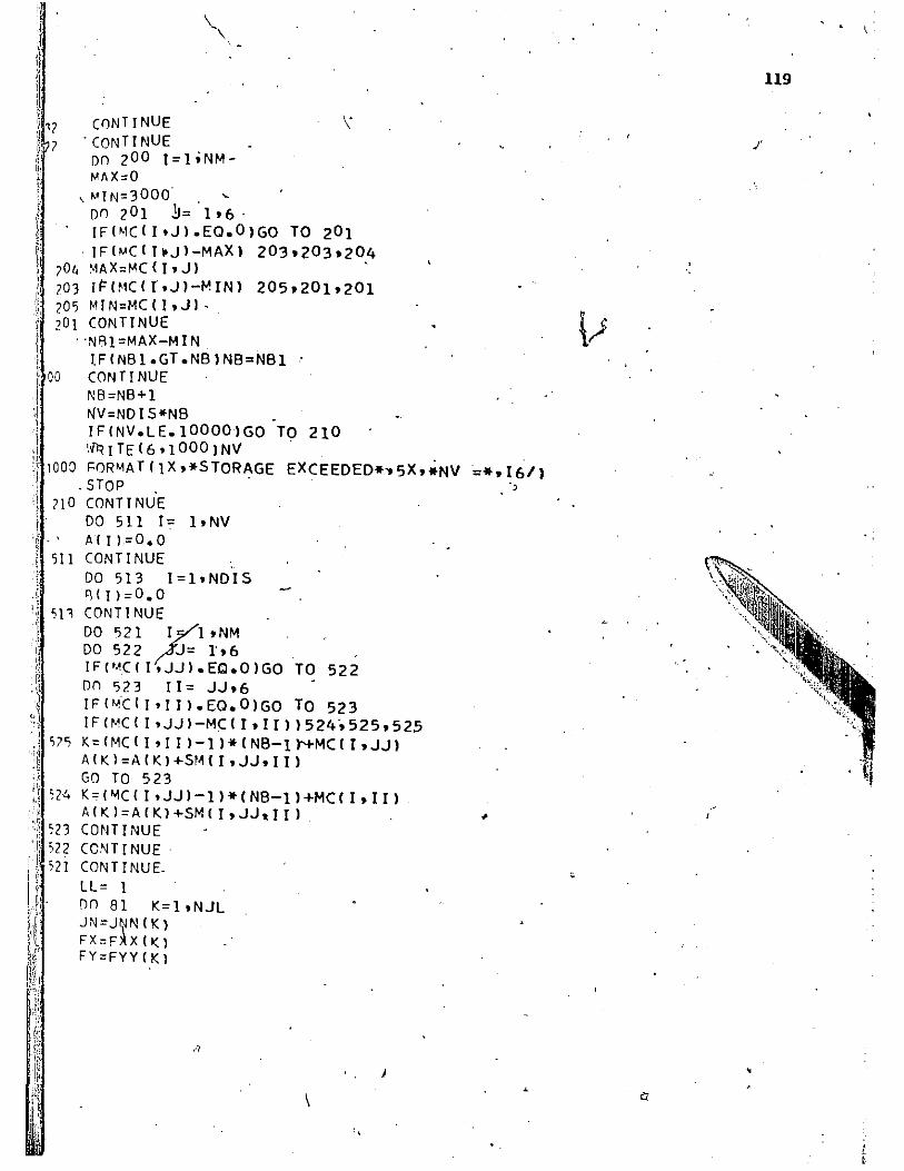
C0NTINUE . CONTI NUE on 2 00 I=l;NMMAX=O
,MIN=3 0 00' , ~ on 20 1 j= 106· IF(MCII.JI.EO.OIGO TO 201
I ,IFIMCII,JI-MAXI 203.203.204 70(, ~AX=MC (" Jl ' 103 IFlf1C1 r.JI-MINI 205.2010201 Z05 MIN=MCIl.JI. 201 CONTINUE
, 'Nfl1 =MAX-M I N LFINB1.GT.NB1NB=NBI CONTI NUE ' NB=NB+l NV=NDI5*NB . IFINV.LE.IOOOOIGO TO 210 "~ITEI6.10001NV '
, 1000 F0RMA T I I X .*5 TOR AGE EXCEEDED* .. 5X. *NV =*. 16/1 . STOP, .
?I 0 CONT! NUE DO 511 1= ltNV A{JI=O.O
511 CONTINUE
57<;
S2-4
DO 513 I=I.NDIS 8(11=0.0 CONTINUE
DO 521 I~l.NM ' DO 522 /.~~ 1'.6 IF(MC( I.JJI.EC.01GO TO 522 on 523 Il= JJ.6 IF("'CII'IIl.EO.01GO TO 523 IFIMCII,JJI-MC(I.III1524.525.525 K=(MC(I,IIl-ll*INB-lt+MCII.JJI A(KI=AIKI+5MII.JJ.III GO TO 523 K=IMC(I.JJI-ll*INB-ll+MCII.III AIKI=AIKI+SM(I.JJ.III
~Z3 cmIT I NUE i 522
, • 52 i CCNTINUE, CONTINUE.
I':
I:'
I·
LL= I DO 81 K=l.NJL IN=J~NIKI FX=FlIX(K) FY=FYYIK)
,'-1
!
\
119
,
,

, ,
"
FMoFMM(K) ~loND(JN.ll IF('Nl.EO.O.AND.FX~E'Q.O,.)GO TO 58 IF(Nl.EQ.O)GO TO 59 A ( ~11 ) ° B ( N 11 + F X • N2 oND(JN.2) , IF(N2.EO.0.AND.FY.EQ.O.)GO TO 61 I'FIN2.EO.0)GO TO. 62 P(N2)oR(N2)+FY . N'oNf)(JN.1) IFIN3.EO.0.AND.FM.EO.0;)GO TO 81 IFIN3.EO.O)GO TO aD R(N3)oB(N3)+F,M
_' GO TO 81 WRITEI6.64)FX.JN, •
120 "
.. FbRMAT(IX. 9HFORCEOF ,.FI0.2,IX.25HKIPS IN HORZ DIR AT JOINT.I3.1X
1033HIS IGNo'RED SINCE JOINT SUPPORT~D.) GO TO SA WRITE(6.6~)FY.JN '. 'Fnp~AT(IX. 9HFORCE OF .FI0.2'IX.?5HKIPS IN VERT DIR AT JOINT,I3,lX 1,3iHIS IGNORED SINCE JOINT SUPPORTED.)' , GO TO 61
WR I TE I 6,66) FM, IN. FORMATIIX'10H~OMENT OF 'FI0.2'lX~15HI~-KIP AT JOINT.I3.1X,33HIS9G I~ORFD SINCE JOINT SUPPORTED.)
~I C('INTINUE Dodo.l E-07 CALL BA~D (A.B.NDIS.NB.LL.DEll IFIDET)266.267.268
?66 \;RITEI6.2691DET :6q FORMA T IlX .*DETER,MI NANT IS NEGATIVE.
STOP • '0 \;PlTF(6;?70)DFT '70 FORMl\T(lX.*DETERMINANT IS ZERO.
- STOP :DA CON T I NUE
\;RITEI6.721
DET=*.FI5.a.ll)
DET =*. 'F 15. a. Ii) 1
F0R~ATI/IHO.40X'*DISPLACEMENT VECTOR*/IHO.20X.62HJOINf NO~ '1015 I IN) VERT DIS (IN) ROTATION (RADIANS) I).
DO 74 Lol.NJ NloND(Ltll N2=ND(L.2) Nl=ND(L.31 IF(Nl) 101 .101 .102
;:2DI(LJ=B(NlI 'Gel TO 103
DI (LJ=O.O
. .
~,
\
HORZ
I
,

~,~~;. '~'f
,;'~
II / ' '0, IFCN'2 I 104.104.105 Ii .100; D2Cl)=BIN21 !' GO TO 106
,":-.
11104 02Cl)=0.0 C 1~6 IFIWlfI 07.1 07'1 0a
1: .10 p D11l)=8IN"I1 , .
'i GO TO 109 ,,1 D1(LI=O.O . ,'i, 107
:~ 10.0 WRITEI6.73IL.D1(l) .D2(U .D3(l) ,~73 FORMAT(20X.I6.6XtFll.6.5X.Fll.6.5X.F14.61"· '" 'CONT I NUE i Ij 74 d . WRiTEC6.75). 1·,li - .
.-
il: 70;' . FORMATCI/IHO.40X.*FORCE VECTOR fN U ? H~E~8ER NO. AXIAL FORCE' (KIPS)
. " ~l
MEMBER COORDINATE*/IHO.20X. SHEAR IKJP~1 JNL 'BM IIN~KIPI ~ 1JNG 8M (IN-~IP) I)
ii': DO 76 M=loNM 11 . Nl=JNLCM)
Ir,· N?=JNGCM)
,J DCll=DlCN,ll
1[,1 DC21=D2CNll .J DC31=D3CNll
"
I: "ii I, I' 4 "
I
·t " ;,r , "I
I
! , 'I , ~
".
D(4)=D1 CN2) DC'i)=D2(N2) DC61=D3(N2) DO 77 1=1.3 FCI)=O'~ , \
DO 77 J=1.6 F C I ) = F C 1 ) +SM (M. I • J ) *D' (,J )
.' .. \
CONTINUE , VF=C-FCl)*YMCM)+FI2)*XMIM»/ALIM) IF=I-FCl)*XMIM)-FI2)*YMIM~)/ALIM) 'l"I=-F(3) ~, R~?=8Ml+VF*ALIM)
wijITEI6,78IM.AF,VF.BM1.BM2 FnRMATCIH .20X.17.5X.F12.4.8X.F12.4~2X.F12.4.6X.F12.41 FACM)=AF FVCMI=VF DV?=C-D(4)*YMIMl+D I 51*XMIMll/ALIM; DVl=C-Dlll*YMIMl+D(2)*XMJMll/ALI~i R'~C I .. I =flM 1 +VF*AL 1M) *0. 50-AF* I DVl, +DV2 1'*0.5 CONTINUE RETURN, END .
121
79,

, I
122
~, SURROUT I NE BANDIA,B,N,M,LT,DETI BNDFOOI0 D'ME~stON AI 100001 ,813001 BNDFOO~O
"M='''-l /'" : . BNDF0030
NM=N*" BNDF0040, ~IMI =NM.,I-'M BNDF0050 IF Ill.NE.I1 GO TO 55 BNDF0060 MP=M+} BNDFOO70 KK=2 '/"
BNDF0080 FAC=DET 1 BNDFOO90 All l~l./S'QRHAI 111
I BNDFOIOO , 1 '
BIGL=AIll ,
BNDFOllO ,
SML=Alll BNDF0120 A 12 I =A 12 I *A I 11 ' I BNDF0130 AIMP1=1./SQRTIAIMPI-AI21*AI211
I BNDF0140 \~- J IFIA(MPI.GT.BIGLIBIGL:A(MPI I BNDF0150 IFIAIMP1.LT.SMLISML=A(MPI H BNDF0160 ..,P=t'P+M BNDF0170 DO 62 j=MP,NMl,M I BNDF0180 , JP=J-MM i BNDF0190' I1 ZC=O ' 1 BNDF0200 IF(KK.GE.MI GO TO 1
1 'BNDFOZIO KK-=KK + l BNDFOZZO 11=1 c;, BNDF0230 JC'=l BNDFOZ40
~,j; I'
l' "
I,
GO TO 2 BNDF0250 KK=KK-+;"" BNOF0260 I,l =KK-I:1" 1 BNDFOZ70 , JC=KK,-M" I BNDFOZ80
'flC) (, Ij I=KK,JP,MM ~'
BNDFOZ90 I F I A I I I'. tQ. O. I GO TO 64 BNDF0300 GO TO 66 BNDF0310 JC=JC+M BNDF0320 "'ZC=MZC+l BNDF0330 ASU'11 =0. BNDF0340 GO TO 61 BNDF0350 ...... ZC=MM~MZC BND!=0360 II=II+M'ZC BNDF0370
, ~I'=KK+M"ZC BNDFb380 AIKI'I=A(KMI*A(Jtl' BNDF0390
IFIKM.GE.JPIGO TO 6 BNDF0400 vJ=KM+rJ'"" -BNOF0410 [)(l 5 I=KJ,JP,MM V 'I BNDF0420
/, SU"2 = O. , BNDF0430
'''=I-I'M ' "
BNDF0440 t BNDF0450
, • 11=11+1
,
K'l = I I +""'1ZC BNDF0460 DO 7 K=KM,IM,MM \ BNDF0470 ASUM2=ASUM2~A(KII*AIKI BNDF0480 vI=KI+I''''' BNDF049Q
1 '
'r.,'", ' ' I( 'l.i
{'
iii, ,t' fl'{' } 'J '~
r; , , q I ,j.~.
AI I I =1 A I I I-ASUM2 )*A KI) CONTI NUE ASU,\U =0. 1)0 4 K=KM,JP,MM ASU~1=ASUM1+AIK)*AIK) S=AIJ)-ASUMI IFIS.LT.O~IOET=S IFIS.EQ.0.1DfT=0. IFIS.GT.O.)GO TO 63 ~lqOW= (J+M~) 1M WRITEI6.991 NROW FORMATC35HOERROR CONDITION ENCOUNTERED IN ROW.I6) RETURN ,AIJI=l./SQRTCS), ("CAIJI.GT.BIGL1BIGL=AIJl IFCACJI.LT.SML1SML=AIJl CONTINUE IFCSML.LE.FAC*BIGLIGO TO 54 GO TO 53 DET=O. ,', RETURN DI"T=SML/BIGL RC 1 I=BC 1 I*AC 11' KK=l Kl=l J=l DO A L=2,N' '1SUMl=O. L"=L-l J=J+!>' IFIKK.GE.M1GO TO 12 KK=I(K+l GO TO 13 KK=KK+M Kl=Kl+l JK=KK DO 9 K=K 1.LM '1SU~1=ASUM1+AIJK1*BCK) JK=JK+MM
'CONT I NUE' RCL1=CBCL1-BSUMll*AIJl BCN1=BCN1~ACNMll n'I"'=~IMl
NN=N-l ND=N DO 10 L=l.NN RSU'12=0.
,...
I'
I , I
I
123,
BNDF0500 BNDF0510 BNDF0520 BNDF0530 BNDF0540 BNDFo55o BNDF0560 BNDF0570 BNDF0580 BNDF0590 BNDF0600 BNDF0610 BNDF0620' BNDF0630 BNDF0640 BNDF0650 BNDF0660 BNDF0670 \ BNDF0680 BNDF0690 BNDF0700 BNDF0710 BNDF0720 BNDF0730 BNDF0740
, \ BNDF0750 I' BNOF0760 1 BNl>F0770 I BNDF0780 I BNDF0790
BNDF0800 BNDF0810 BNDF0820 " BNDF0830 BNDF0840 BNDF0850 BNDF0860 BNDF0870 BNDF0880 BNDF'0890 BNDF0900 BNDF0910 BNDF0920 BNDF0930 BNDF0940
I
.~ I 1 I
I , I
I I , ! '
BNDF09.50 BNDF0960

) NL=N-L NLl =N-L +1 ~"I-'=N"''''-I-' NJ1=NMM IF(L.GE.MIND=ND~1 , " DO 11 K=NLl.ND NJ1=NJl+l RSU"'2=BSUM2+A(NJll*B(KI
I: I CONTI NUE , ! ~ B(NLJ=(B(NLI-B5UM21*A(NMMI , i RETURN
E"JD
~:)
(
I
/ .,
"
-
i;.
, I I
,!
I
·1
, . , i . ,
, . , , >, I
124
BNDF0970 BNDF09BO BNDF0990 BNDFI000 BNDFlOlO BNDFI020 BNDFlO30 BNDFI040 BNOFI050 BNDFI060 BNDFI070 BNDFlOBO

"
125
SU8ROUTINF MPHTIPAXTAL;AMOM.STRATN.CURVA.WEF~.WU.NM.UUFI.WTE.KONT 5 ,Tl,T21 .
t :,i '34 , '
I "
COM~ONI BLOCK 1/OTH .OB .AST, ASC .OST .OSC COM~ON/BLOCK3/W~YRS. WSHRC COMMON/ALOCK4 / WIENSTL. WV'FSV'FCVL. TCF' NALLOW. ES COMMON/BLOCK5/P~ITRI.WTRIAL ~IMFNSIONWGI20.201.WHI20.201
DI~FNSI~N WEEPI20'201.WUI20'201~UUF1120'201 NSTRIP=2.0 KADD=O NEK=O CCA=5.0E-04 CCB = 1.0E-I0 EROR=O'OI KDD= a P = PAX TAL fJM = BMOM TDEL= T2 - Tl W = WTRIAL 'P'HI = PHITRI WCF = 145.0 E"C ,; 1,.*WCF**I.C;*1 FCVL*1000~1**0.50/1000." \;SHRS = I OF> *0 TH-AST -IISC I *EC,*WSHRC I I I AS T +AS(") *ES I
" KOUNT = 0 ," .. " t L'~ = KONT ~ IrIT212388,2388,3377
'Re CYL = FCYL "
" J 1RB DO 3388 LN= I. NSTRTP WEEPILM.L~I= 0.0 GO TO 444
'77 FC I = FCVL IF1T 2.LF..O.0.OR.TOEL.EQ.0.1 GO TO 4~4 CYL =ll.O+TCFI*FCI IFIJ2.CE~120.1 CYL = (1.0+TCF*T2/120.1*FCI CONTI NUE . CALL BMPtALIW.PHI.PCALI.BMCALI.WU,WEEP.CYL.W4.LMI ~OUNT = KOUNT + I . IFIKOUNT.GT.40IEROR=0.02 IFII(OU'JT .GT .60IEROR=0.05 IFIKADD.GT.OI Go TO 848 IFIW.GE.2.0*WTRIA~.ANO.TI.GT.0.01 GO To 608 IFIP.EQ.O.I P= 1.0 ) IFIRM;EO.O.IBM= 1.0 ERRI = ABSIIP-PCALII/PI FRR2 = ARSIIBM-BMCALlt/BMI IFIP.LE.1. 0 .ANO.ABS(PCALll.LE.3.001 ERRl=O.Ol IFIA~S(RMI.LE.IO.OI ERR2=ABSIBM-ABSIBMCALIII/IOO.0
i~ II ',j
I{
plJ
-'" . ,) ~"Ir I,', I ! ~ ',,'
'1 t. I. !
,,J ,
i:,·.,1 " ;
"
IF(£RRl.LE.ERdR.AND.ERR2.LE.ERORl GO TO 600 IFIAASCRM1.LE.I0.01 GO TO 7712 (,(1 Tn ,1)12 .ROR~ 0.,0 , IFI'1MCALl.LE,.fO.O.AND.ERRl.LE.ERORl GO TO 600 IFIT?GT.O.AND.BMCALI.LE.IO.OI GO TO 60~ CONTINUE ' lFIP.LE.l~O.AND.ERRl.EQ.O.Oll GO TO 103 (,0 TO 203 IFIKADD.EO.II GO TO 944 IF(KADD.GT.Ol GO TO 60Q WINC = CCA*W + CCB PHINC = CCA*PHI+CCB IFIWI~C.EQ.O.O.OR.PHINC.EQ.O.OI GO TO 608 WNFW = W + WINC ' PHINEW = PHI ~ PHINC CALL R~PCAL(W.PHINEW.PCAL2.8MCAL2.WG.WEEP.CYl.W7'lM) CALL R~PCAL(WNEW.PHI.PCAl'.BMCAL'.WH.WEEP.CYl.WR.lMl All =(PCAL2-PCALll/PHlNC
LA12 = (PCAL3-PCALII/WlNC Al1 = P - PCALl
,An = (BMCAL2 - BMCALll/PHlNC .A?? = (,BMCAl3-BMCALII/WINC
A73 = AM - BMCAll RR = Al1*A22-A21*A12 IF·IRR.EO.O.l GO TO 608 \WE'L = (A 1 l-*-A23-A I'HAn l/RR PHIDEL = (A13*A?7 - A73*Al21/RR PHI = PHI + PHIDEL VI = W + WDEL IF(KOUNT-NALLOWI436.436.60A ~TD·\IN = W CUPVA = PHI \>TE= W4 W'= 0 IF(C~RVA.LE.O.l GO TO 60A qnURN WRITE16.6661 , '(lDVAT(1H.40X.*+++++++++++++++++++++++++++++++++++++++++++*1
. KOUNT=O W=WTRIAL DHI=PHI TRl ':ADD=l (,0 TO 436, SUD=AASt(W-W41/WI IF(P.FO.l.O) NEK=O IF(NEK.EO.l1 GO to 898
126
•

,', " " :1.7
':\
: ~ ~
:j .'j
"I
IF(SUP-O.051 642.641.641 UPI =0.0001 * (P-PCIILlI / <'10. *p I IF(P.LE.I 0 • 0 1 U~1=O.0001*(P-l.*(PCAllll/(10.*ABS(PCAL111 GO TO 640 UPl=ABS(W-W41*(P-PCALll/(lO.~PI IF(P.LE.IO.OI UPl=ABS(W-W41*(P-l.*(PCALlll/(10.*ABS(PCALlll UC =W+UPI .• UT =W4+UPI NEK=l' GO TO BB8 IF(SUP-0.051 675.671.671 , UP2=0.0001,(BM-BMCALll/(10.*BMI IF(BM.LE.I 0 • 0 1 UP2= ,0.0001 *(BM-BMCALll/(lO.O*ABS(BMCALlll GO TO 65B ' UP2~ABS(W-W41*(BM-BMCALll/(10.*B~1 IF(~M.LE.I0.01 UP2=ABS(W-W41*(BM-AMCALll/(lO.0*ABS(BMCALlll UC =W+UP2
,UT =\.,4-UP2 NEK=O GO TO '888 SUP=AAS « W-W41 /W.l IF(SUP-0.051 945.946.946
, ; 'UP~=AASrW4f(W-W411*0.OOOl*(AM-AMCALlll(10.*qMI
IF(RM.LE.10.01 UP1=ABS(W4/(W-W411*0.000~(BM-eMCAL11/(10.O*ABS( ~ ~IJO L 1 I I' ' ,-' U~?=ABS(W /(W-W411*0.OOOl*(BM-BMCALll/(10.*BM1' IF(~M.LF.I0.01 UP2=AAS(W /(W-W411*O.0001*(BM-AMCAL11/(10.0*ABS(
S ~MCALlil' • GO TO '947 UP3=ABSiw41*(BM-BMCALll/(10.~BMI' 4
IF(AM.LE.IO.OI' UP3=ABS(W41*(BM-BMCAlll/(10.0*ABS(BMCALlll UP2~A9S(\" 1*(BM-BMCALl li( 10.*BMI ','
\, IF(o\~.LF.l0.01 UP;>=ABS(W 1*(BM-OMCAlll/(lO.O*ABS(BMCALlll uC=\>I,+UP2 ' ~
UT=W4-UP3 PHI=!UC-UTl/DTH W=UC W4=UT tF(W.GT.IO.0**51 GO TO 123 IF(l«()UNT-I00I' 436.436.123 \'IR tTF (6,19,8 I F()RIJAT(lH .40X.*- - - -N'1= l' STRAIN = 0.0015 CURVA=0.0002 RETURN END
~ - - - - - - - -
/
,
127
, /

'J
SURqOUTINF CREFPIWEEP.WU.UUFl.KO~Tl.Tl.T21 nl~CNSln~ W~cpI?0'701.WUI20.201.UUFlI20'701
'NSTRIP=20 ' AI = -1.03050E+06 ' A2 = 5.e4~870E+02 A3 = - 3.776740E-Ol 44 = - 3.J7225 0 E-06 ,qr = 1.858390E+06
• 1'12 = -I !.012295E+03 n3=1.5215225E+00 R4'~ -7.98625 00E-06 L=KONTI
,
IF(Tl.GT.O.OI GO TO'87 SfiR I"NK ='-0.000111 +0.0002 24*ALOG 1 0 IT 2 I GO TO 88 , IF(T?GT.700.1 _ GO TO 129 SHRINK=O.000224*IALClGIOIT2)-ALOGIOITll) GO TO 88' _
SHRINK = 0.000224*IALOGI01700.) SSRR= SHRINK IF(Tl.GT.700.) SSRR = 0.' 'IFITl.GT.O.O) GO TO 67 DO 69 I = 1.NSTRIP CLU=\~U(L.I ) X= CLU
f
128
:'
'; IFI X )124;1~.125 , 1 )~ - WEEP(L.I)=(Al*X**3+A2*X**2+A3*X+A4)+(Bl*X**~+B2*X**2+B3*X+B4)* '. I ALOGI01 T2l+ SSRR ,'-
i,
UUFl (L .r 1 = X GO T069
?4 \,!E,EP( L. II = SSRR UUFlIL.r I = 0.0 (oONTI NUE RETURN ' , r:' DO 7,5 I - 1. NSTRIP CLU = \W(Ld) X = CLU
,
IF( X 1988.98a.987 OLDU= (X -UUFr(L,Ill y ='OLDU IF(Y.LF.O~OI GO T0998 50Ln=(~1*Y**3+A2*Y**2+A3*Y+A4)+I~I*Y**3+R2*Y**2+R3*Y+R41*ALOGIOIT2 .. ~ -,
1 -TIl -' . GO T0999 SOLD=O.O , ~FEPIL.Il=(Bl*X~*3+B2*X**2+B3*X+B4)*(ALOGI6IT2)-ALOGlOITl))+SSRR+
1 SOLD+WEEP(l.I) UUFJ(Ldl= CLU
I
"
) ,/

" ','
'1:1
GO TO 75 WEEPIL,ll=WEEP(L,ll+SSRR UUFllL.q= o. CONTI NUE RFTURN END
••
129'
'.
•
".\

I I
: '!'\
!
. :,
'; ,
A
SUBqOUTINE BMPeALIW.PHI.peAL.BMeAL.WU.WEEP.eYL.W4.L) COMMON/BLOeKl/DTH'PB.AST.ASe.OST.oSC· COMMON/ALOeK3/WSHRINS. WSHRINe C0MMON/RLOeK4/ WTENSIL. WY.FSY.FeYL' TeF' NALLOW. ES D!MFNSION WEEPIzO.ZO). WUIzO.zO) NSTRI?=20 OL = OTH/NSTRIP . DCGe,= I08*OTH**Z*0.S+AST*OST+ASe*OSel/IDB*OTH + ASe + AST) \n = W , . \
ONAXIS = WI/PHI . W? =IONAXIS - osel~PHI W3 =IONAXIS - OST)*PHI ~4 = PHI*IONAXIS-OTH) OX = DeGe + O.S*DL peON = 0.0 '3~eON = 0.0 Da 100 I = 1. NSTRIP DX = DX - DL.
+ WSHRINS' +WSHRINS
WUIL,I I=PHI*IDNAXIS+OL*0.50-6L*FLOATI I» ~WEEP{L.II - WSHRINC WX = WUIL.Il· I '
!FIWX+WT~NSIL)10.Z0.20 STRESS = 0.0 GI)"TO 30
130
S TRFSS=("Yt. * I -4. <;00S07C1f:+09*WX*"'4+7 • 6164509F +07*WX**3-4. R02<'754F+0 5 1 *WX**2,+1.190262AE+03*WX) peO~CR = STRESS*08*OL A~CONe = PCONeR *ox' DeON = 'peON +.PCONCR gMeON = BMeON + ~MeONe CONTINUE IFIW?EO.O.) W2 = 1.0
. IFIW~.EO.O.O) W3 = 1.0 WA= ABSIW2) WB=IABS 1W3) STEEL2= FSY*W2*IWA+WY-ABS(WA-WY»/12.0*WY*WAI STEEL3= FSY*W3*IWB+WY-ABSIWB~WY)I/12.0*WY*WRI !F(W2.EO.0.1 STEEL2= 0.0 !FIW1.EQ.0.) STEEL3=0.0 PS2 = Ase~STEEL2 PS3= AShSTEEL3 RMS2 = PS2*IOeGe-Ose) ~~S3 = PS3~IOeGe -OST) PCAL = peON +PS2+PS3 . R~eAL = AMeON + BMS2+BMS3 :<ETURN END
6400 END OF RECORD
/
"

•
',I
ILLUSTRATING EXAMPLF
FORSETJING T~E COMPUTER DATA
\ FOR A_ S I NG.LF COLU~N.
131 . - ,
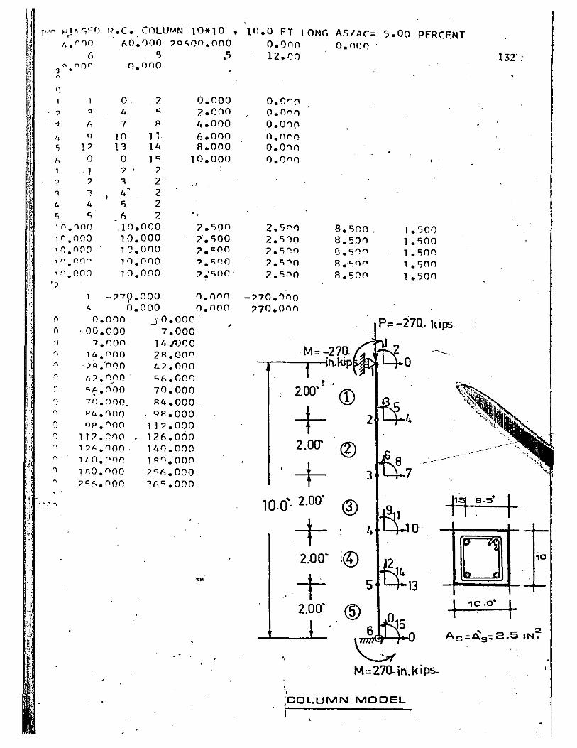
i
I'· ,!
r,,'n f-l r 'I"FO , li.nnn
R.C. CnLU~N 10*10 , 60.000 70~0(l.Ono
6 5 ,5 ~ "on 3 •
~
" 1
? ~
1 f,
I. " <; P
(l.noo
o ? 4 S
7 I'
10 11 11 14
0.000 ?OOO 4.000 6.000 8.000
!. I) o 1" 7' ;> "I 2 4' 2
10.000 . 1
? 7 .>
~ ~
4 4 I) 2 <; S (, ? 1".'1(10 .10.000
10.000 10.000 10.(100 10.000
1n.000 'tl.n("l(l 1~.r:()'"
'''.000 ';i
-;>79. 000 !. 0.000
'I 0.0110 .J 0 • 000 n ,00.000 7.000 '1 7.r:On 14,(01)0 'I 14.f"Ino ?R.O(ln
" .?Q .'n I") 0 6.7.000 .~ I,::> .1'"I: .. f'!O ' "1'1.000 'I "~.(100 70.000 'I 70.0!)(). '14.000 'I P4.(100 01'.000 0 op.noo 117.000 r: 117.(1'10 126.000
" 1?"-.'100· 14(l.nOD
" llLO. 0 f)f'! lq'1.000 'I lRo.noo ;>"".000 , ?sf..noo ~AS.OOO 1
. ~,,"';'\
7.1)0(l 7'.1)00 ,.c:.00 ?c;~O
,.1£:)00.
o.ono 0.000
,
10.0 FT LONG AS/AC= 5.00 PERCENT o.ann 12.00
0.0"0 0.0"11 0.0':10 0.Or0 0.0"10 /').0"11
2.<;"11 ?liOO ?t;nn ',. c:; '"'tn ?<;no
-;>70.'1"0 '70.011()
O.OO(l . 132' !
8.500, 1.1)0f) 8.5,011 1.500 S.lion 1.linn fl.,t;nl' 1.C;O(l 8.50(l 1.500
p= -27Q. kips .
M=-27U -----·n.kip 0 8 ,
2.00' CD it4 + 2
2.mT ®
+ 3
10.0" 2.00' ® ~ + 4 0
2.00' !®
+ 5
2.00' ®
M=270.in.kips. \ ,
MOOEL
r, B.~· I
D I

!
\
APPENDIX, B
CEB-DESIGN EQUATIONS
FOR REINFORCED CONCRETE
COLUMNS
BY EUROPEAN CONCRETE COMMITTEE(13).
133
/
/'

APPENDIX B
CEB DESIGN EQUATIONS
This section is ,copied directly from ref. (13) and is pro~ 'here for easy reference.
CROSS SECTION STRENGTH
Although there are no equations fot combined axial load "and , , r
bending in the CEB Rermmendations (13), a set of such equations was
proposed in CEB Bulletin No. 31, and are given below:
1. Tied column section controlled by compression
where
a = 4 d-d! 1+2Ptm -t-
2. Tied column section controlled ,tension
'p = 0.76f' bt[-Il .+ IIl2 + U C
where
Il ="e/t - O.S
d-d' 1.1Pt!' t )
The CEB does not giyc equations for spiral columns and under ,
the heading, "CR4.132, Meml!.ers Reinforced by binding", they state:
"Th~ binding is efficient only for short columns and
slight eccentricities. ,For long columns reinforced
by binding, the influence of binding on the buckling
J
134

\
is very small and there is often premature failure
of the column by bursting."
135
_ SLENDE~ CQLUNNS
The CEB Recommendations treat slender cQlumns-in the following
manner:
R4 :141: Axially Loaded Columns
For analyzing slender members with regard to failure. an additional-
moment N; is introducted which will be added to loadings calculated by the
first-order theory
where
N = characteristic value of the normal force. assumed calculated
according to first-oroer theory. multiplied by the load in-
crement coefficient y s
ht = total geometric depth of the sectiQn measured parallel to )
the bending-plane
eo = eccentricity of the normal force in- relat/on to the center of
gravity of the concrete section alone. calculated according
to first-order theory. if there is a transverse bending moment
Eb ~ longitudinal strain modulus of the concrete. kg/cm2
0E = Euler st~ calculated on the elastic theory. with-the
value chosen for t~e Eb modulus. taking into account the
effective configuration of the system concerned
Ys
= lolld factor usually taken as 1.4 (defined :ii\ CEB R2~321)

j. 136
I CR4:l4l: Axially Loaded Columns
For columns with 'constant inertia and a rectangular cross section,
the expression of the additional moment ~ given in the Recommendations, '-
may be written 1 2
(ph) t
where '1 is the free length of the column and p is the munerical coeffi-
cient taken equal to:
26, if the member is free at 'one end and fixed at the other.
52, if the member is articulated (hinged) at both ends. J
52, if the member may be c;:onsidered as fixed at both ends, the
ends being capable of moving in relation to each other in'a' , .
direction perpendicular to the longitudinal axis of the
""~ , 'member and situated in the principal plane for which buckling
, is investigated. •
75, if the member is "articulated (hinged) at one end and fixed ,"" at the other.
" For multistory ~uildings, wh~e~ the cohtinuity of the columns and
thej.r sections is assured, p 'shall be taken equal to:
75, if the e\ds of the ~olumn are fixed
or connec\ed to floor beams with an
in the foundation-slab
inertia at least similar
in the direction in question and running through it from one
side to ~he other.
52/ll+O.75r' if the'ends of the column ~e free to sway, where
EI EIb r' " l LeO T L Io
,~
,
,

60 in all other cases .• -
For ~ally loaded columns, an additional moment need not,be
taken into account when the slpnderness, in the Euler sense, is less
than 40. ~ f
CR4:143: Exceptional Influences
The ordinary elastic and plastic strains induced by a load,
whatever its duration; are. included in the additional moment. Excep-
137
~ tiona 1 influences are .those capable of increasing the transve~se strains
undulY, for instance, of a long-term load. Among th~se influences may
be reckoned those of creep, in some cases, and those of vibrations due
to resonance.
For the time being, i~ossiMe ·to proceed 'as follows. for
iE.stance if it' seems necessary to take i'nto account. for the design of
sections, the exceptional effect of a long-term io~ OV. where t repre
sents the ratio of this load to the total lond,.the additional moment
~ must be multiplied by (l+~t). c,
The ·value of ~, which takes into account the effect of time, .'
will be.between 0 to I according to the magnitude of the expected
'plastic strains, a 'value ~f 1/3 seems generally acceptable.
Similarly, if the effect of vibrations has_ to be takep. into
account, the additional moment ~ may be multiplied by (l+¢), where c
¢ is between 0 and 0.4.
J ..
,
.'

BIBLIOGRAPHY
1. ACI Cotmnitt'ee Report, Buildin CodeRe uirementsfor Reinforced Concrete CACI, Standard ,318-63 '" American Concrete Institute,' 1963.
2. ACI Committee Report, Buildin Code Re uirements for Reinforced Concrete, CACI 'Standard 318-71 , Amencan Concrete Instlt'ute, 1971.'
, b 3. Breen, J .E., The Restrained Long Column as ,Part of a Rectangular Frame,
Ph,.D. Dissertation, University of Texas, :JWle 1962.'
4. Broms" B., Viest, M., Ultimate Strength ASCE Vol. 126, 1961, pp. 309-397.
of Hinged Columns, Transaction '\
5. Broms, B., Viest"M., .~U71~t=i~ma~t~e~S~t~r~e~n~~h~~~~~~~~~~~~~~ forced Concrete Columns, 1510, January 1958.
6. Broms, B., Viest, Proceedi~gs ,
M., Design of Long Reinforced Concrete Columns, ASCE, V.84, No. ST4, Paper 1694, July.1958. '"',
7. Chang, W.F., 'Ferguson, P.~I., Long Hinged Reinforced Concrete Columns, ACI Journal, Vol. '61, No.1, January 1963, pp. 1-25.
8. Chang, !,I.F., Ferguson, P.M., Critical Length -of Long Hin~ed and Restrained Concrete Columns, ASCE and ACI Flexural Nee anics of Reinforced Concrete, Proceedings of the International Symposium, 'Miami, 1964.
9. Danielson, C.T., Sustained Load Behaviour of Reinforced Concrete Frames, M. Eng. Thesis, McMaster University, 1970.
10. Drysdale, R.G., The Behaviour of Slender Reinforced Concrete Columns Subjected·to Sustained Biaxial Bending, Ph.D. Thesis, University of Toronto,1967.
II. Drysdale, R.G., Prediction of the Behaviour of Concrete Frames, symposium of the Design of Concrete Structures for Creep, Shrinkage andTemperature Changes, International Association of Bridges and Structural Engineering, Madrid,. Spain, 1970, pp. 395-404.
12. Emery, J.J., ~htrix Methods ~f Structural Analysis, Graduate Course No. 713, Department of Civil Engineering and Engineering Mechanics, Hamilton, Ontario, Canada.
, 13. European Concrete Committee, Recommendations for an International Code
of Practice for Reinforced Concrete, English translation published , ,
138 \

139
by ACI and C. and C.A., 1964.
14. Cranston, W.B., Tests on Reinforced Concrete Frames' ill Portal Frames with Fixed Peet, TeChnical Report, Cement and Concrete Association (U. K.) London, TRA-'420, September 1969.
15. "
16.
p.
18.
, 20.
Green, R., Behavior,lof Unrestrained Reinforced Concrete Col=s Under Sustained Load, Ph.D. Dissertation, University of Texas, 1966.
Ferguson, P.M., Reinforced Concrete Fundamentals, John Wiley and ,Sons, 2nd. Edition, 1965.
Furlong, R. 1'1., Long Col='5 in Single Curvature as aPart" of Concrete Frames, Ph.D. Dissertation, University of Texas/ 1963.
Furlong, R. \'I,., Col= Slenderness and Charts for Design, ACI Journal , Proceedings, January 1971. " ' "
Johnston, B.C., The Col= Research Council Guide to Design Criteria for Metal Compression Members" 2ud~ Edition, John '~iley and Sons, Inc., N.Y., p.'217., , "
MacGregor, J. G. , Design of Slender Reinforced Concrete Co1=s', Structural Concrete Symposium, Toronto, May 1971.
21. NacGregor, J.G., Breen, J.E., Pfrang, E.On Design of Slender Concrete Col=s~ ACI Journal, January 1970,pp. -6-28,. ,
22. ~Ianuel, R.F., MacGregor, J.G., Analysis of Restrained Reinforced Concrete Under Sustained'L9ads, Ph.D. 9issertation, University of Alberta, Edmonton, Alberta,' Canada, 1967.' ' ,
23. Martin, I., MacGregor', J. G., Pfrang, lind Breen, Critical Review of the Desi'gn of Reinforced ConcreteCol=s, Symposium on Reinforce'd Concrete Columns, SP-13, ACI, Detroit, 1966, pp. 13-53. ' . . . "
24. National Research Comicil of Canada, Canadian,Structural Design Manual, AssoCiate Conmdttee on the NBC, Ottawa, 1970.
, "
25., 1'oel J., Everar-d, and EdwaXd. Cohen, Ultimate Strength'Design of Reinforced Concrete Col=s, Interim Report of ACI Conmdttee 340, ALI P)lblic~pon SP-,7.
~ ,
26. ,Parme, A.L., Capacity of Restrained Eccentrically Loaded Long Columns, Proceedings, ASCE,'Y.84, No. ST4, Paper 1694; July 1958.
27., Pfrang, E:O. and Siess,' Predicting Structural Behaviour Analytically, Proceedings, }'sCE, Y. 90, No:, ST5:, October 1964~ pp. 99-112. '
28. Portland Cement Association, 'Notes on ACI 3l8-71,BUllding Code ReqUire-ments with DeSign Applications, PCA Publication, Illin9is, USA, July 1972.
\

29. Robinson;·A., Gurfinke1, G., Determination of, StraIn-distribution and . Curvature in a Reinforced Concrete Section Subjected ,to Bending
Moment and Longitudinal Load, ACI Journal, July 1967, pp. 398-402.
30. SYlI1posium on Reinforced Concrete Columns, ACI Publication SP-13, " California, March 1965. '
140
,31. Tan, K.B., On Short-Term imd Sustained-Load Analysis ,of Concrete Frames, M. Eng. Thesis, McMaster University, 1972.
•