OTT DuoSens Training Dec 2011-...
61
• Meassuring • Processing • Store DuoSens Application
Transcript of OTT DuoSens Training Dec 2011-...

• Meassuring
• Processing
• Store
DuoSens
Application

•Tranamission via SMS /GPRS
• Alarm via SMS
• Transmission via satellite
DuoSens
Application

DuoSens
General Features
Optical interface (IrDA)
Jog-shuttle
- RS232- Relay- Voltage Switch
- Voltage input- Current input- RS232 (e.g. Nimbus)- RS485 (e,g Kalesto)- Pulse input (e.g. Rainguage)- SDI 12 (e.g. Hydrolab probes)
Display

netDL500 / netDL 1000
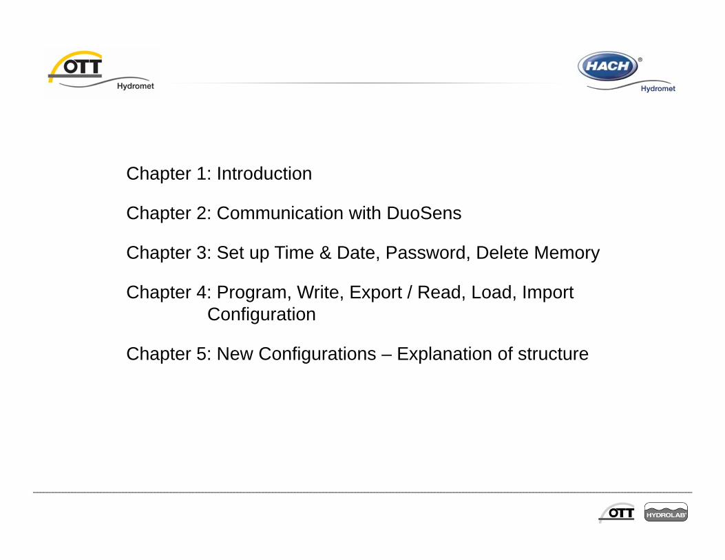
Chapter 1: Introduction
Chapter 2: Communication with DuoSens
Chapter 3: Set up Time & Date, Password, Delete Memory
Chapter 4: Program, Write, Export / Read, Load, Import Configuration
Chapter 5: New Configurations – Explanation of structure

Chapter 6: Communication interface
Chapter 7: Alarm Management
Chapter 8: GPRS Settings
Chapter 9: Channel Configuration (Sensors!)
Chapter 10: Print Configuration
Chapter 11: New Program Code (Firmware)
Chapter 12: Terminal Mode (for advanced users)

1 - Introduction
• Short description
• DuoSens: Highly configurable data logger• SDI, Impulse and Analogue input channels, 1 output channel, 4 MB ring buffer,
jog shuttle, …
• Configuration Program:DuoSens, DuoSens 2, DuoSens
• Explanation of functionality• Showing an example• Exercise and solution• Hints• Practise

2 – Communication with DuoSens
• Choose right COM Port, Speed: Auto
• For on site communication the IrDA with OTT DuoLink is recommended, sometimes RS232C is used.
• For remote communication choose AT-Modem/Adapter
• Press desired function (next chapter).
• For Modem/ISDN type in number (plus pre-dialling string) and e. g. for ELSA Microlink 56 k initialisation string.

2 – Communication with DuoSens
• Check date and time of DuoSens via direct communication (IrDA) and via modem (GSM):
• 1. Choose IrDA OTT Duolink, choose COM Port 1, Speed: Auto, Choose DuoSens/ Date & Time
• 2. Choose AT-Modem/Adapter, choose COM Port 1, Speed: Auto, Choose DuoSens/ Date & Time, type in telephone number, no pre-dialling string, check Hayes compatible
• After checking the date click on ‘Cancel’ to exit the date & time area.
• Then click on ‘Exit’ to stop communication (especially on remote parameterization via Modem or ISDN).
.

3 - Time & Date, Password, Delete Memory
• All Functions for DuoSens operations are listed under menu ‘DuoSens’
• Read configuration from DuoSens
• Program configuration to DuoSens
• Check and set date / time
• Delete data memory
• Enter Terminal mode for all functions (for advanced users)
• Enter password (access only to authorised persons)
• New firmware for DuoSens (new functions etc)
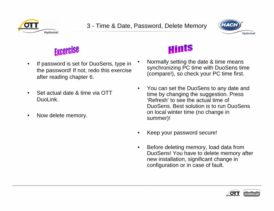
3 - Time & Date, Password, Delete Memory
• If password is set for DuoSens, type in the password! If not, redo this exercise after reading chapter 6.
• Set actual date & time via OTT DuoLink.
• Now delete memory.
• Normally setting the date & time means synchronizing PC time with DuoSens time (compare!), so check your PC time first.
• You can set the DuoSens to any date and time by changing the suggestion. Press ‘Refresh’ to see the actual time of DuoSens. Best solution is to run DuoSens on local winter time (no change in summer)!
• Keep your password secure!
• Before deleting memory, load data from DuoSens! You have to delete memory after new installation, significant change in configuration or in case of fault.
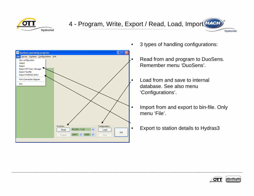
4 - Program, Write, Export / Read, Load, Import
• 3 types of handling configurations:
• Read from and program to DuoSens. Remember menu ‘DuoSens’.
• Load from and save to internal database. See also menu ‘Configurations’.
• Import from and export to bin-file. Only menu ‘File’.
• Export to station details to Hydras3
4 - Program, Write, Export / Read, Load, Import
• Set up communication to DuoSens. Read configuration from DuoSens.
• Then program configuration back to DuoSens, write configuration in internal database and exportconfiguration to external file (e. g. c:\programs\ott\logocnf\files\test.bin).
• Now load configuration from internal database and import configuration from external file (see above).
• Before programming a new configuration to DuoSens first read configuration and export it with name ‘…old.bin’.
• Actual configuration should be stored in internal database.
• If someone needs your configuration, export it to filename ‘…act.bin’ and transfer your file to the network (or just save it to disk). Then the user can import it to use it e. g. for another DuoSens.
5 - New Configurations – Explanation of structure
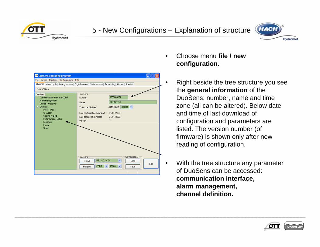
• Choose menu file / new configuration.
• Right beside the tree structure you see the general information of the DuoSens: number, name and time zone (all can be altered). Below date and time of last download of configuration and parameters are listed. The version number (of firmware) is shown only after new reading of configuration.
• With the tree structure any parameter of DuoSens can be accessed: communication interface, alarm management, channel definition.

5 - New Configurations – Explanation of structure
• Read configuration from DuoSens. Check download time and version number. Save configuration to internal database.
• Create new configuration, change number (123456789), name (‘first test’) and time zone (‘-4h’, important for satellite communication). Save configuration to internal database.
• Program this configuration to DuoSens.
• Read configuration from DuoSens. Check download time again.
• To ensure that you don’t write the false configuration to the DuoSens, first read configuration and compare station number.
• Setting up a password (e. g. last four digits of telephone number) is another possibility to prevent overwriting with wrong configuration (see next page).

6 - Communication interface
• RS232 interface can be used for modem/adapter, satellite communication (METEOSAT/GOES) and SDI communication (RS232 disabled).
• Submenus are General, Modem/ Adapter, METEOSAT/GOES, SDI-Slave, SMS-Data(only visible after choosing GSM-Modem with SMS).
• Baud rate has to be selected for modem/adapter only. Activation control via relay contact is only available for modem/adapter.
• Data bits, Parity and stop bits are fixed. Address number can be used as password to prevent unauthorized data transfer.
• Password (max. 8 char: 0-9, A-Z)
6 - Communication interface
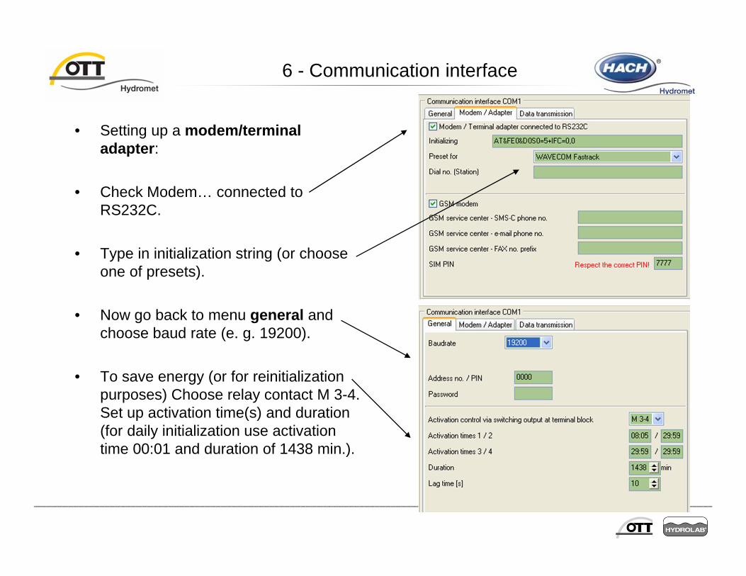
• Setting up a modem/terminal adapter:
• Check Modem… connected to RS232C.
• Type in initialization string (or choose one of presets).
• Now go back to menu general andchoose baud rate (e. g. 19200).
• To save energy (or for reinitialization purposes) Choose relay contact M 3-4. Set up activation time(s) and duration (for daily initialization use activation time 00:01 and duration of 1438 min.).

6 - Communication interface
• Settings to send SMS (messages and data), fax and email (only messages):
• Check ‘GSM modem with SMS’• Type in GSM service center
phone no.
• SMS data functionality• Special program ‘SMS Receiver’ needed!• Check ‘Transmission SMS’• Cycle standard: e. g. 6 h • Cycle limit event: e. g. 1 h• Number of SMS receiver (Base Station)• No. of max. following SMS: 1• Check sensors for transmission

7 - Alarm Management
• Alarm will be send on special conditions to address group.
• Click ‘New’ to enter new address.
• Alarm message to mobile phone via SMS:
• Type in mobile phone no.• Choose modem/adapter• Choose SMS• Choose Text• SMS prefix: prefix for SMS text
• Alarm message to fax and email is similar!

7 - Alarm Management
• Alarm message to Hydras 3: • Type in phone no. of Hydras 3
computer• Choose modem/adapter• Choose modem passive• Choose OTT protocol standard• Choose no. of dealings• Choose reading pause (min.)
• Alarm message to terminal program• Type in phone no.• Choose modem/adapter• Choose modem active• Choose protocol type ‘text’

7 - Alarm Management
• Alarm with external device (e. g. Bell, Flashing Light):
• Choose relay switch output
• Choose M1-2
• Choose OTT protocol standard
• Choose switch time (s), 0 means on/off will last till next variation.

7 - Alarm Management
• Other alarm possibilities:
• To activate cycle limit for SMS data transfer.

7 - Alarm Management
• Alarm can be sent only to address group:
• Click on Address groups / New
• Type in Name
• Drag & drop address from right to left window
• To delete address from group: mark address and press ‘del’

7 - Alarm Management
• Set up alarm-address with SMS message to your mobile phone.
• Set up alarm-address for Hydras 3 alert.
• Set up alarm-address-group with all three addresses.
• You can set up different alarm levels (values run over/under specified limits). These can trigger different alarm addresses. So depending on the limit you should send emails (uncritical)

8 – GPRS Settings

8 – GPRS Settings

• Select your Service Provider ( SIM Card)
• Automatically assigns Operator fields
8 – GPRS Settings
• Enter the server Info
• Case Sensitive
• Operator Independant
Passive FTP is recommended (not possible with the eDevice modem) . If issues occur try active FTP
Attention: for server path use „/“ to separate different levels andnot the common one from Windows „\“. See example above!
Server path might beleft blank but if defined,it has to exist!
9 - Channel Configuration
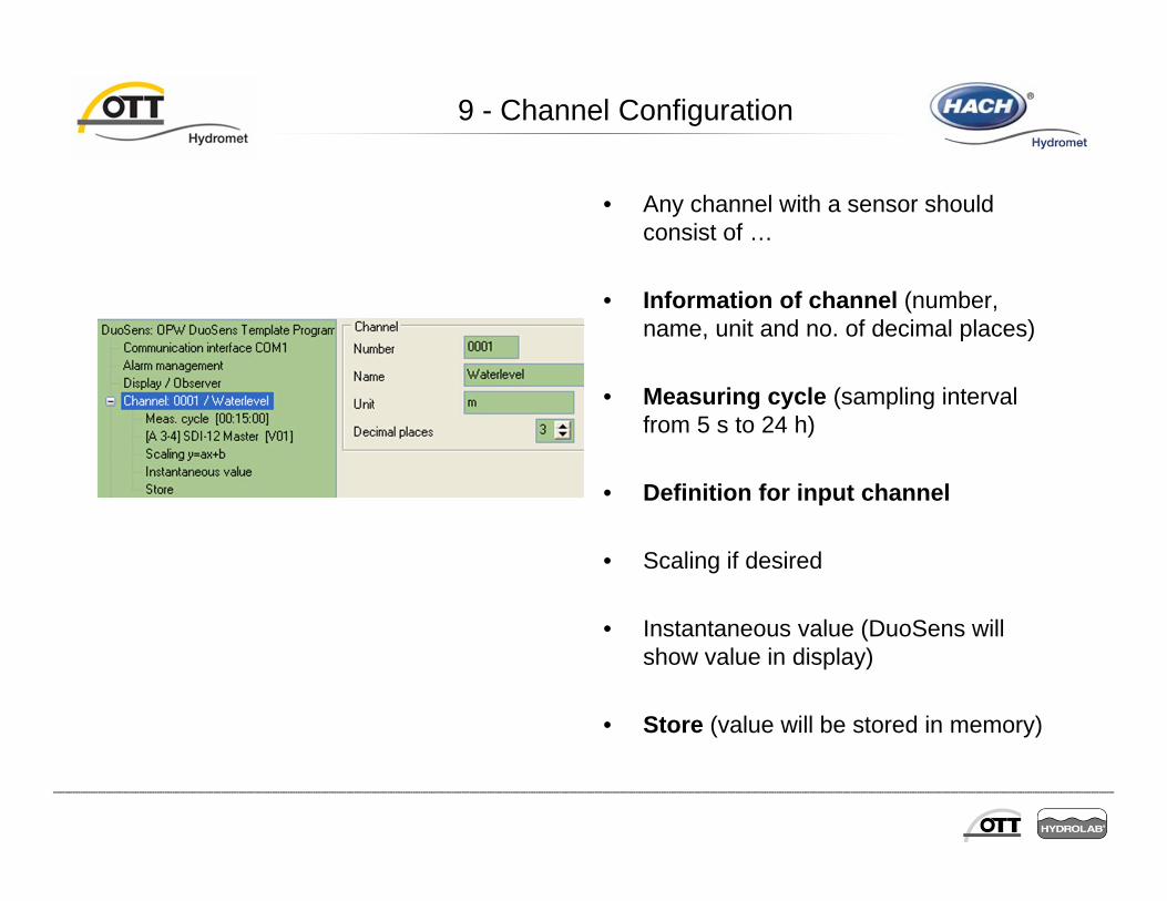
• Any channel with a sensor should consist of …
• Information of channel (number, name, unit and no. of decimal places)
• Measuring cycle (sampling interval from 5 s to 24 h)
• Definition for input channel
• Scaling if desired
• Instantaneous value (DuoSens will show value in display)
• Store (value will be stored in memory)
Channel Configuration
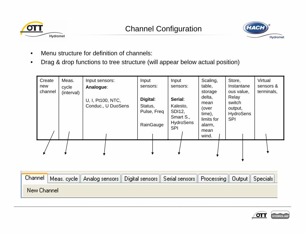
• Menu structure for definition of channels:• Drag & drop functions to tree structure (will appear below actual position)
Create new channel
Meas.cycle (interval)
Input sensors:Analogue:
U, I, Pt100, NTC, Conduc., U DuoSens
Input sensors:
Digital:Status, Pulse, Freq
RainGauge
Input sensors:
Serial:Kalesto, SDI12, Smart S., HydroSens SPI
Scaling, table, storage delta, mean (over time), limits for alarm, mean wind.
Store, Instantaneous value, Relay switch output, HydroSens SPI
Virtual sensors & terminals,

Channel Configuration
• DuoSens will work through configuration from top to down one channel after the other. Channel will be handled only if measurement cycle is triggered by internal time.
• Create new configuration. • Click on ‘channel’.• Drag & drop ‘new channel’ before
existing channel. (New channel is now the first one in workflow)
• Click on ‘meas. cycle’, drag & drop ‘meas. cycle internal’.

Channel Configuration
• Set number (0001), name (‘Water Level 1’) and unit (‘m’) of sensor. Set meas. Cycle to 1 min. Complete new channel with SDI 12 (on terminal block ‘A 3-4’), scaling, instantaneous value and store.
• Create another sensor at the end of configuration:
• Number: 0002• Name: ‘Temperature’• Unit: ‘C’• Meas. Cycle: 15 min.• Sensor: Virtual Sensor [ V01]• Scaling, instantaneous value, store
• Order of channels can’t be changed after definition.
• Do delete definition, mark row and press ‘del’. Channel can’t be deleted before all adjacent channel-configurations are deleted.

Channel Configuration
• Virtual sensor and virtual terminal(V1 to V64)
• Allows a very wide variety of functionality:• Some sensors apply values to normal sensor
and to virtual sensor• Access to virtual sensors is very fast (normal
sensors delay program: meas. time).• Allow complex calculations.• Duplicate Sensors for output in different units
(m and feet).• Complex limit definitions.
• First apply value (actual value in channel) to virtual terminal.
• Now value can be accessed with virtual sensor.

Channel Configuration
• Mean arithmetic (4x) Sum, difference and mean of up to 4 values
• You have to define virtual sensors for input first. Output is set to actual value in channel and can be applied to virtual terminal.
• Mode can be set to• (1 + 2 + 3 + 4) / n• 1 + 2 + 3 + 4• 1 – 2 – 3 – 4
• (n is number of valid virtual sensors)

Channel Configuration
• Mean (in time domain)
• Mean interval should be multiple of measuring interval (3 min. > 6, 9, 12,15 min.).
• Can be used for highly altering values and to save memory:
• Set meas. cycle to 1 min.• Set mean to 15 min. (1 good value)• Values will be stored with 15 min.
interval.
Channel Configuration
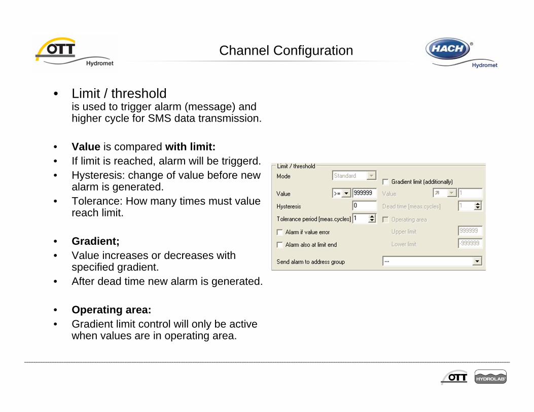
• Limit / thresholdis used to trigger alarm (message) and higher cycle for SMS data transmission.
• Value is compared with limit:• If limit is reached, alarm will be triggerd.• Hysteresis: change of value before new
alarm is generated.• Tolerance: How many times must value
reach limit.
• Gradient;• Value increases or decreases with
specified gradient.• After dead time new alarm is generated.
• Operating area:• Gradient limit control will only be active
when values are in operating area.
Channel Configuration
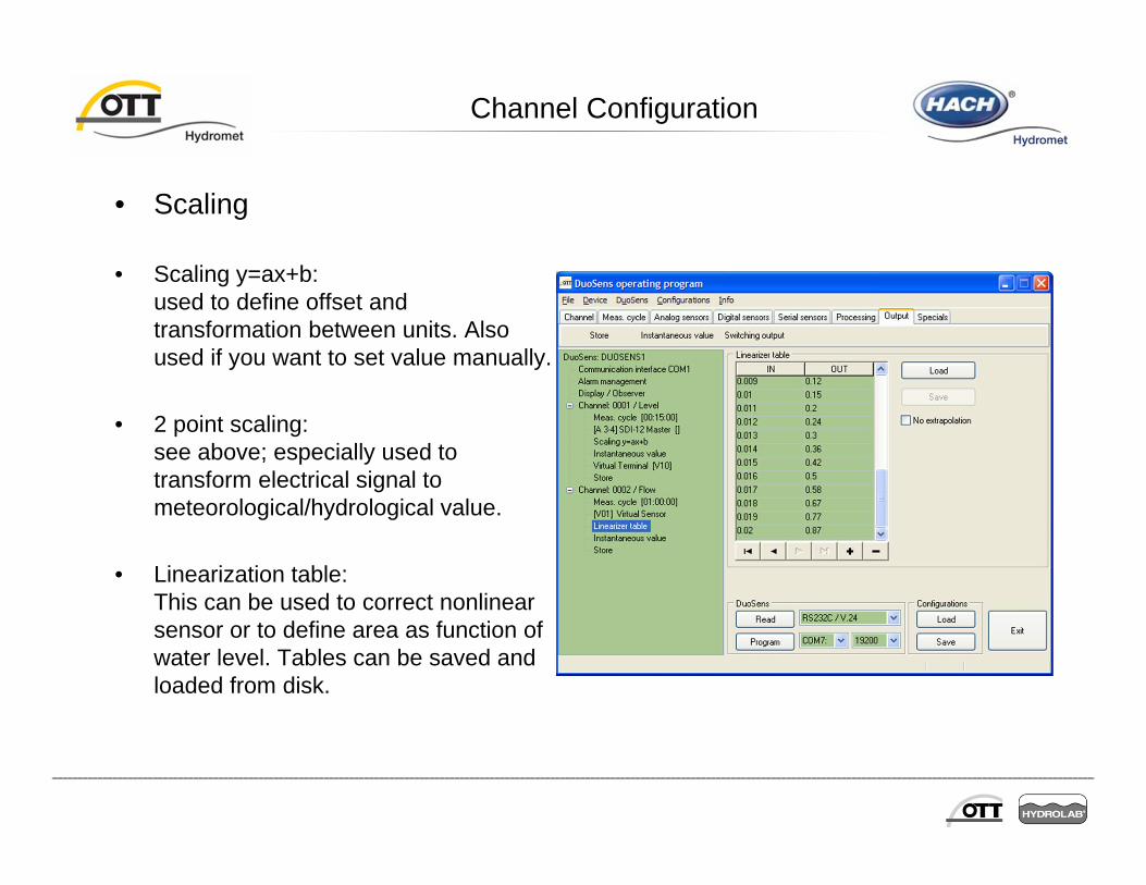
• Scaling
• Scaling y=ax+b:used to define offset and transformation between units. Also used if you want to set value manually.
• 2 point scaling:see above; especially used to transform electrical signal to meteorological/hydrological value.
• Linearization table:This can be used to correct nonlinear sensor or to define area as function of water level. Tables can be saved and loaded from disk.

Channel Configuration
• Storing and Output
• Storage delta (submenu processing):useful for precipitation; will filter data if there is no change in value, store is still needed.
• Store:Values are stored in memory.
• Relay function M 3-4:switch on or off for specified seconds.Former status will be lost, hard on/off.
• .

Channel Configuration
• Now try to write your own configurations.
• Play around with functionality.
• Try different sensors.
• Set up alarms
9 - Print Configuration
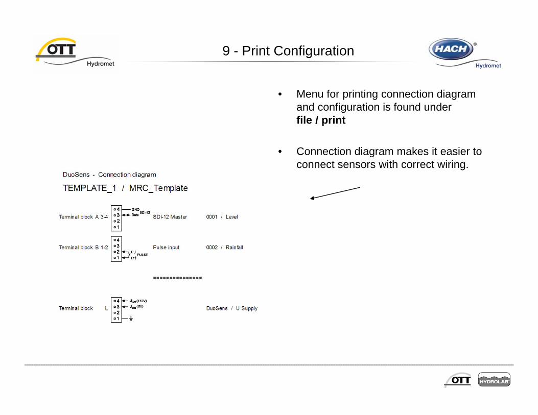
• Menu for printing connection diagram and configuration is found under file / print
• Connection diagram makes it easier to connect sensors with correct wiring.

9 - Print Configuration
• Configuration in DuoSens operating program can’t be seen with all details at once (you have to click on any row to see the details).
• But you can export configuration in file (which can be printed) in two formats (examples of the configuration on right is shown on next page).

9 - Print Configuration
• Configuration can be printed as normal textfile (see right) or as XML-file (see below, tags shown with MS Internet Explorer).
DuoSens: Number: 0000071101Name: OPW DuoSens Template ProgramTimezone: UTC/GMT +00:00Activate DST for display and output: No
Communication interface COM1: General:
Baudrate: 19200 (8N1)Address no.: 1111Password: -Activation control via switching output at terminal block: M 3-4
Activation times 1 - 4: 09:30 / 29:59 / 15:00 / 29:59Duration ( 1..98, 99 = always on ): 60minLag time [s]: 10 s
Modem / Terminal adapter connected to RS232C: YesInitializing: AT&FE0&D0S0=5+IFC=0,0Dial no.: 0873293306GSM modem: YesGSM service center - e-mail phone no.: GSM service center - FAX no. prefix: PDU send string 1 (first 3 octets/SMSC) [octets]: 001100PDU send string 2 ( PDU-PID / -DCS / -VP ) [3 octets]: 00F6AA
Self timed data transmission mode: 1Cycle Standard: 24hTransmission start time offset: 07:15Cycle Limit event: 2hCycle Limit event: 2hCycle Limit event: 2hCycle Limit event: 2hCycle Limit event: 2hDial no.: 0874124494Protocol type: OTT protocol binaryMaximum number of additional SMS per transmission: 2Channel(s) transmitted: 0001
Inmarsat-C transceiver connected to RS232: NoORBCOMM transmitter connected to RS232: NoSDI-12 connected (RS232 disabled): No
Alarm management: Address gro ups:
Display / Observer: Observer Manual input: Yes
Calculate manual input value with scaling: YesSuppress display of instantaneous value before input: No
Extended observer (store and transmit number): NoPassword for display ('Address No. / PIN' of COM1): Yes
Date / time operation: Date and time
Channel: Number: 0001Name: WaterlevelUnit: mDecimal places: 3
Meas. cycle: Sample interval: 00:15:00
SDI-12 Master: Terminal block: A 3-4Slave address: 0Measurement mode: M!Value no.: 1
Value no. Virtual Terminal ID
Etcetc
<STATION>
<DEVICETYPE>OTT DUOSENS</DEVICETYPE>
<STATIONID>0000071101</STATIONID>
<STATIONNAME>OPW DuoSens Template Program</STATIONNAME>
<STATIONUTC>+00:00</STATIONUTC>
<STATIONPHONENO1>0873293306</STATIONPHONENO1>
<SENSOR>
<SENSORID>0001</SENSORID>
<SENSORNAME>Waterlevel</SENSORNAME>
<UNIT>m</UNIT>
<RIGHTDIGITS>3</RIGHTDIGITS>
<AXISLABEL>Waterlevel</AXISLABEL>
<INTERVAL>9000</INTERVAL>
</SENSOR>
<SENSOR>
<SENSORID>0002</SENSORID>
<SENSORNAME>Watertemp.</SENSORNAME>
<UNIT>°C</UNIT>
<RIGHTDIGITS>1</RIGHTDIGITS>
<AXISLABEL>Watertemp.</AXISLABEL>
<INTERVAL>36000</INTERVAL>
</SENSOR>
<SENSOR>
<SENSORID>0003</SENSORID>
<SENSORNAME>Voltage</SENSORNAME>
<UNIT>Volt</UNIT>
<RIGHTDIGITS>2</RIGHTDIGITS>
<AXISLABEL>Voltage</AXISLABEL>
<INTERVAL>36000</INTERVAL>
</SENSOR>
</STATION>

• Now you are able to Export a configuration in a format, which Hydras 3 can import.
• Benefit: The names of station and sensors are taken over. Telephone number is insert on communication properties.

10 – Hydras3 Settings
• Select Station Properties
• Make sure to enter ‘1111’ as a password to access the data remotley if the password is set on the display of the DuoSens
•Select OK

10 - New Program Code (Firmware)
• DuoSens can be updated with new program code (Firmware) to implement new functions (e. g. update to V1.12 enables GPRS data transfer).
• Click DuoSens / new program code. Click Yes.
• If no connection is established, follow instructions.
• Normally memory has not to be deleted.
• Direct transfer is recommended (remote connections sometimes break down and DuoSens could freeze in). At least you should have the possibility to drive to the station in case of failure.

11 - Terminal Mode (for advanced users)
• In terminal mode all functions of menu ‘DuoSens’ can be accessed with direct command and some more.
• Any command begins with ‘CL/…’
• Type CL/Help (and Enter) to list all commands with syntax and explanation.
• If problem occurs with DuoSens please try CL/Rebuild.

Connection and configuration of sensors

12 – Things to remember
• RS485 (OTT SDI) is a bus system. The first and the last device of the busshould include a shunt resistor of 120 (CBS has dip switches to selectRS485 with or without shunt). DuoSens has the shunt included (for thededicated RS485 input), LogoSens not (because of universal inputs).
• SDI-12 input at LogoSens needs an additional connection of Gnd of thesensor (e. g. terminal block A3+A4) to Gnd of LogoSens (terminal blockT3). You should also use a 4,7 k shunt resistor for the SDI-12bus (till now skipped in OTT systems without problems).
• SE200 should be powered permanently (even during storage) to preserveinternal battery
• 4-20 mA output of LogoSens as well as for all new OTT sensors is passive– that means you need to set up a loop including power supply (checkmanual).
• First program configuration, then connect sensors.

12 – Connections
•Check manuals of sensor (and datalogger) for physical connection!
• In general use RS485 connection(OTT SDI) if possible: longer distancebecause of high disturbanceresistance (with twisted wires).Binary mode for firmware update(LogoSens, especially DuoSens)
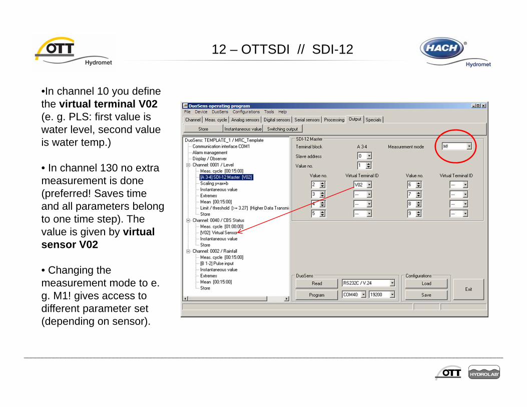
12 – OTTSDI // SDI-12
•In channel 10 you definethe virtual terminal V02(e. g. PLS: first value iswater level, second valueis water temp.)
• In channel 130 no extrameasurement is done(preferred! Saves timeand all parameters belongto one time step). Thevalue is given by virtualsensor V02
• Changing themeasurement mode to e.g. M1! gives access todifferent parameter set(depending on sensor).

12 – Storage Delta
• Use storage delta module forprecipitation measurement tosave memory andtransmission time!
• Can be used also for groundwaterstations with slow/seldomchanges of water level (e. g.change has to be 2 cm or greater).
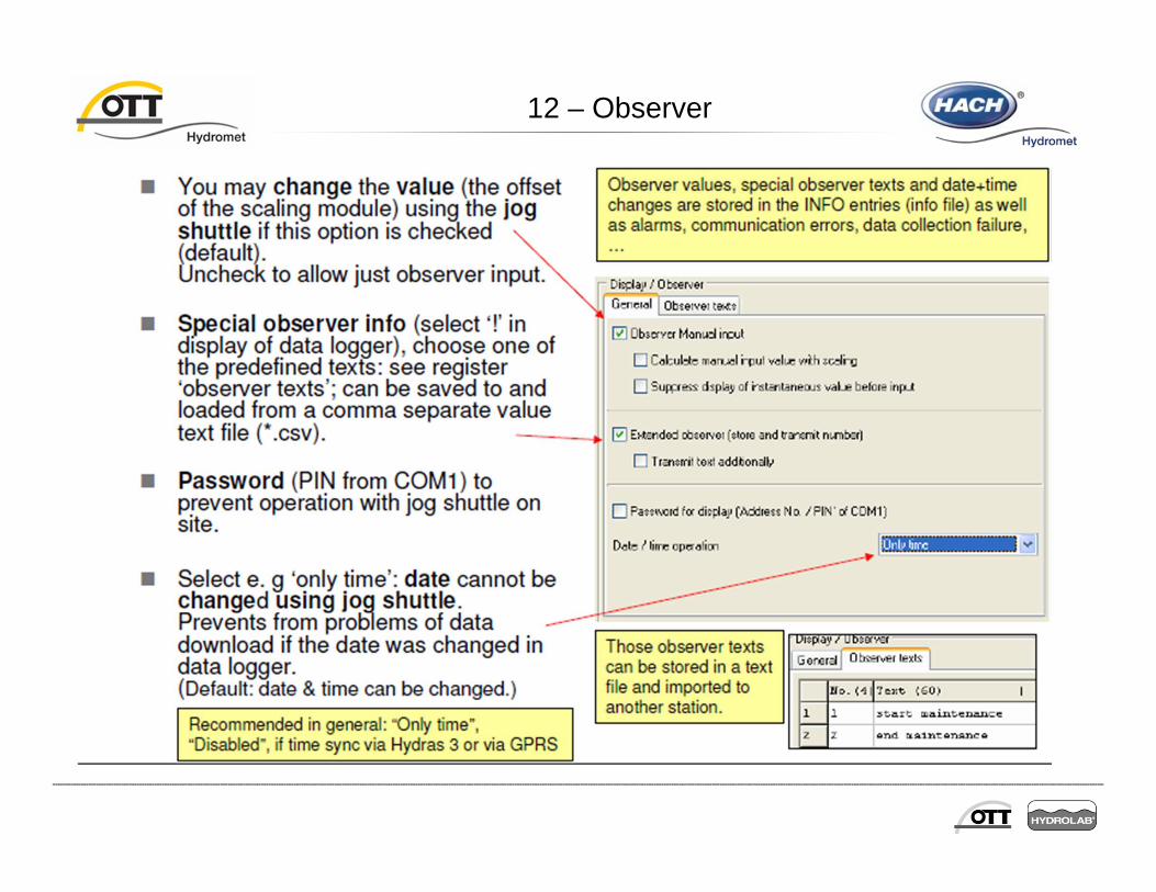
12 – Observer

•Physical connection and modem settings
• Protocols and data format:
• Software + Data transmission of DL (passive / active)
• Time sync:.
Communication

Baud Rate

MIS Format / OTT binary format
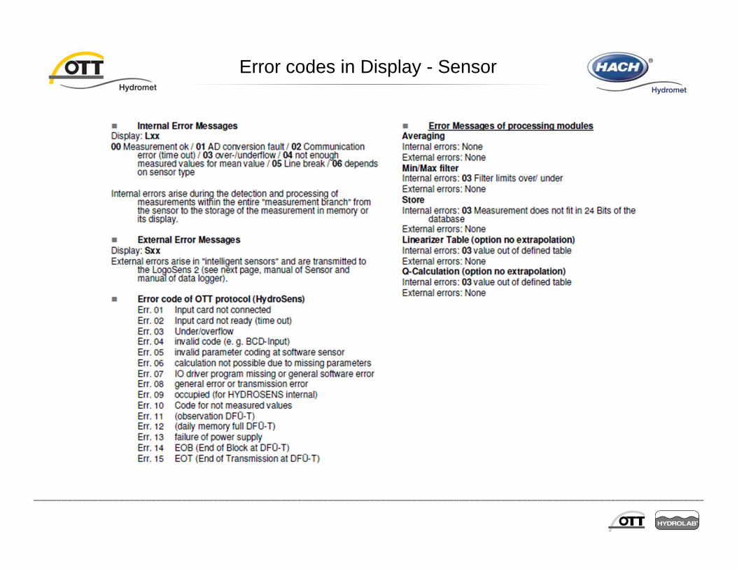
Error codes in Display - Sensor

Error codes in Display - Sensor

Error codes in Display - communication

Error codes in Display - communication
Testing
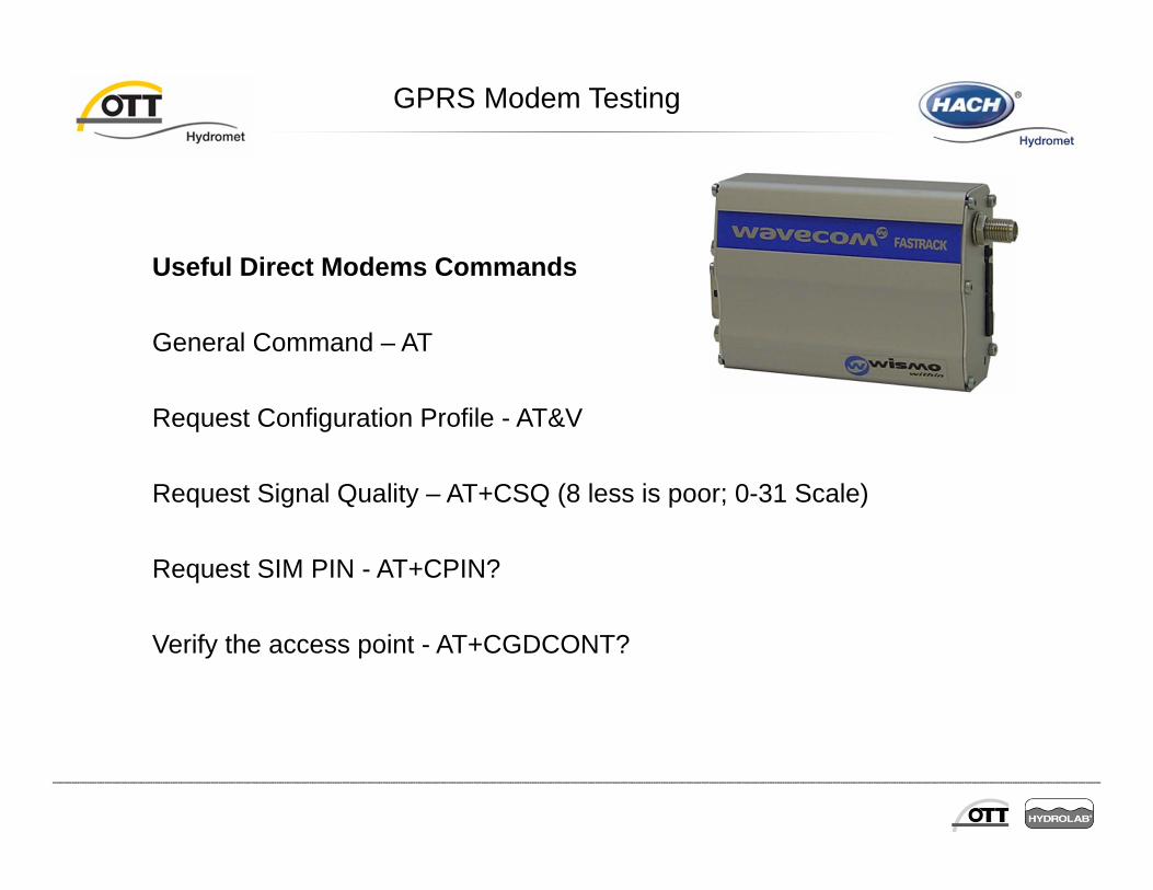
GPRS Modem Testing
Useful Direct Modems Commands
General Command – AT
Request Configuration Profile - AT&V
Request Signal Quality – AT+CSQ (8 less is poor; 0-31 Scale)
Request SIM PIN - AT+CPIN?
Verify the access point - AT+CGDCONT?