OTQt – Conversion Of Spatial 3D Data Into Qt Application...
20
Seminar Thesis OTQt – Conversion Of Spatial 3D Data Into Qt Application Mouse Events Author Christian Pirchheim * Supervisor Dipl.-Ing. Alexander Bornik Department Institute for Computer Graphics and Vision Graz University of Technology Inffeldgasse 16/II A–8010 Graz Abstract This article describes OTQt, an add-on module to the tracking data flow library Open- Tracker. The module converts dedicated tracking data into desktop mouse events and posts these events to Trolltech Qt desktop applications. OTQt addresses a usability problem that may emerge in hybrid 2D/3D AR environments where 2D and 3D scenes are operated with different interaction devices. The resulting frequent physical exchange of interaction devices may cause fatigue. The presented approach is the simulation of the desktop mouse with tracked input devices. Test results have shown that the module does not only cope with basic mouse behaviour such as cursor moving and button clicking, but is also capable of simulating more complex operations such as drag-and-drop. Basically, OTQt provides a “TabletPC feeling” by employing tracked input devices to operate 2D desktop applications, and thus enhances the usability of 2D displays in AR environments. Keywords: hybrid 3D/2D AR environment, tracked input devices, desktop mouse, Open- Tracker, Trolltech Qt * [email protected]
Transcript of OTQt – Conversion Of Spatial 3D Data Into Qt Application...

Seminar Thesis
OTQt – Conversion Of Spatial 3D DataInto Qt Application Mouse Events
AuthorChristian Pirchheim∗
SupervisorDipl.-Ing. Alexander Bornik
DepartmentInstitute for Computer Graphics and Vision
Graz University of TechnologyInffeldgasse 16/II
A–8010 Graz
Abstract
This article describes OTQt, an add-on module to the tracking data flow library Open-Tracker. The module converts dedicated tracking data into desktop mouse events and poststhese events to Trolltech Qt desktop applications. OTQt addresses a usability problem thatmay emerge in hybrid 2D/3D AR environments where 2D and 3D scenes are operated withdifferent interaction devices. The resulting frequent physical exchange of interaction devicesmay cause fatigue. The presented approach is the simulation of the desktop mouse with trackedinput devices. Test results have shown that the module does not only cope with basic mousebehaviour such as cursor moving and button clicking, but is also capable of simulating morecomplex operations such as drag-and-drop. Basically, OTQt provides a “TabletPC feeling” byemploying tracked input devices to operate 2D desktop applications, and thus enhances theusability of 2D displays in AR environments.
Keywords: hybrid 3D/2D AR environment, tracked input devices, desktop mouse, Open-Tracker, Trolltech Qt
1
1 Introduction
The idea for OTQt emerged from an usabilityproblem within an existing hybrid AR environ-ment, which consists of a 3D display as wellas a conventional 2D desktop screen, notably anotebook. Further, the 3D scene displayed on astereoscopic projection wall is operated by someoptically tracked input device similar to a pen,while the 2D desktop screen is operated with aconventional desktop mouse. Thus, 3D and 2Ddisplays employ different input devices. An ARapplication, which takes advantage of both dis-plays faces the necessity of frequent changes ofthe interaction device. Putting away the pen-device in order to grab the desktop mouse andvice-versa causes fatigue on the application user.A possible solution is the construction of a singleinteraction device for 2D and 3D display. Theapproach presented here is the simulation of thedesktop mouse with tracked input devices, thusthe operation of the 2D desktop application withthe 3D interaction device.OTQt links the tracking data-flow library Open-Tracker with Trolltech’s Qt for desktop appli-cations. The OTQt module receives trackingdata from OpenTracker, converts it into differ-ent kinds of Qt mouse events and posts themto the target application via standard Qt APImethods.OTQt benefits from both foundation libraries:designed as an module extension of Open-Tracker, it inherits its ease of configuration de-scribing complex tracking setups with intuitiveXML documents. The preprocessing of track-ing data can be done exploiting the rich set ofreusable operations contained in OpenTracker.On the other side, the Trolltech Qt API pro-vides powerful static methods for posting mouseevents and retrieving required UI data. The in-tegration of OTQt into an existing Qt projectdoes not require writing additional classes ormechanisms in the target application. Appli-cations implementing OTQt can be ported toany operating system for which Qt and Open-Tracker are available. Thus, using the Qt li-brary as mouse event feed was preferred overplatform-specific low-level feeds such as the Xwindow system.The following sections are dedicated to the baselibraries of the OTQt module: the OpenTrackerlibrary is presented in Section 1.1, followed by abrief summary of Trolltech’s Qt and its API fea-tures in Section 1.2. Section 2 gives descriptions
of several research projects related to OTQt.Section 3 lists some of the design criteria ofOTQt followed by Section 4, which covers theactual implementation. Finally, in Section 5 thetests with OTQt are summarized followed by anoutlook on future OTQt versions in Section 6.
1.1 OpenTracker
OpenTracker2 ([8]) is basically a generic data-flow network library which deals specificallywith tracking data and is designed to be used inVR and AR environments. It addresses differentrequirements towards the processing of trackingdata:
• support of different tracking devices andextensibility towards new tracking devicedrivers
• distribution of tracking data to differentsoftware components on several host com-puters
• flexible configuration of complex hard-ware setups and rapid customization offrequently changing experimental trackingconfigurations
• compatibility with different application ar-chitectures and easiness of integration
• fast delivery of tracking data to minimizelatency added to the overall process
Typically tracking data passes through a seriesof steps. It is generated by tracking hardware,read by device drivers, transformed to fit theneeds of an application and transported over thenetwork. OpenTracker derives its main conceptfrom this observation, that is, to break up themanipulation of tracking data into individualsteps and thus to provide a pipe-and-filter ar-chitectural pattern. This concept allows to ab-stract recurring operations, make them reusableand separate the operations from the applica-tion. Thus, OpenTracker forms an architecturallayer between the tracking devices and the ap-plication.Each operation step can be seen as node in adata flow graph. Within this graph the track-ing data passes from children to parents. Eachchild applies its specific operation on the current
2http://studierstube.icg.tu-graz.ac.at/
opentracker/

2
tracking event and forwards the modified eventto its parent. Each node consists of one or moreinput ports and output ports. Different types ofconnections between two nodes are possible:
• one input port connected to one outputport (basic linear connection)
• multiple input ports each connected to adifferent output port
• one input port connected to several outputports (fan-in)
• one output port connected to several inputports using references (fan-out)
Simple child to parent event passing may not beconvenient for some node’s computations. Forexample, noise and smoothing filters typicallyoperate on a set of tracking data. OpenTrackertakes regard by declaring different edge types.The type of an egde is defined by the type ofthe input and output port, which must coinci-dence by definition. The possible edge types areevent edges, which provide a push pattern, eventqueue and time dependent edges, which providea polling pattern. All nodes implement one ofthe interfaces defined by their respective edgetype. The different interfaces provide certainmechanisms concerning the event passing fromchildren to parent node:
event new events are pushed from children totheir parents
event queue parent queries the child for thenumber of stored events and retrieves themby index
time dependent parent retrieves events fromthe child by specifying a point in time
The implementation of the data flow graphand node concept distinguishes between differ-ent types of nodes. Source nodes are consideredto be the leaves in the graph receiving their in-put from external sources (tracking hardware,network). Filter nodes are considered as inter-mediate nodes, which modify and filter the datareceived from other nodes. Sink nodes shouldpropagate values to external outputs.OpenTracker consists of a small number of coreclasses, which build the framework for the im-plementation of node classes and the runtimeengine actually processing tracking data. An
application using OpenTracker must initialize aContext class object, whose interface providestracking data flow runtime methods. The appli-cation may use a predefined main loop methodor implement an own tailored routine usingmethods from the public interface. During ini-tialization of the Context object a number offactories implementing the NodeFactory inter-face are registered. A node factory is responsiblefor the creation and initialisation of node objectsregistered at the factory with their name. Incommon, a node factory also derives the Moduleinterface, which provides the methods called bythe runtime main loop. A module may combinea number of associated nodes to form a morecomplex working unit, such as a device driver.The nodes itself must implement the Node inter-face which does provide methods for querying itsparent and children nodes and incorporates theedge type interface. Each node class must de-clare, which edge type interface it implements.It is not obligatory that nodes have an under-lying module. In order to realize the multipleinput port per node requirement a special nodetype called wrapper node is introduced.OpenTracker instances are configured with oneXML file (refer to the following section for anexample). The file generally consists of two sec-tions: one module configuration section and thegraph section itself. The data flow graph is rep-resented by nested XML elements. During theinitialization of the Context object, the XMLfile is parsed and the resulting document ob-ject model (DOM) is mapped to a data flowgraph. Each Node class is identified with itsunique XML element name and the associatedattribute values are passed to the concrete Nodeobject which is created by the correspondingmodule. Some modules demand to be initial-ized in the prepending module configuration sec-tion. The XML file can be created using stan-dard XML tools on basis of a provided documenttype definition (DTD) file. The DTD expressesobligations and restrictions regarding the overallstructure of the configuration file and the combi-nation and nesting of XML node elements form-ing a data flow graph.
XML configuration file example
Within the following configuration file, Open-Tracker is advised to read recorded trackingdata from a file source and propage it to ancurses form on the console screen as well as

3
to a network UDP multicast address:
<?xml version="1.0" encoding="UTF-8"?><!DOCTYPE OpenTracker SYSTEM "opentracker.dtd"><OpenTracker>
<!-- (I) --><configuration>
<!-- (A) --><ConsoleConfig headerline="File ->
[Console, Network]"display="on"curses="on" />
<FileConfig interval="0.1" /><!-- (B) --><NetworkConfig />
</configuration><!-- (II) --><!-- (a) --><ConsoleSink comment="Position / Buttons">
<!-- (c) --><FileSource station="1"
file="position_buttons.dat"DEF="file1" /> <!-- (IId) -->
</ConsoleSink><!-- (b) --><NetworkSink name="File2Network"
number="1"multicast-address="224.0.0.10"port="1234"interface="192.168.0.8" >
<!-- (d) --><Ref USE="file1" />
</NetworkSink></OpenTracker>
The configuration file is generally parted inmodule configuration section (I) and graph sec-tion (II). Within the console module configu-ration (A) the console output is enabled andncurses output is enabled via the appropriateattributes. The network module configurationelement (B) employs no attributes and couldbe omitted. The data flow graph consists ofsinks towards the console (a) and network (b),reading recorded traffic data from a file source(c) marked with a reference identifier. The filesource data is redirected to the network sink us-ing a reference with the previously defined iden-tifier (d).
1.2 Trolltech Qt
Qt by Trolltech3 is a C++ toolkit for GUI ap-plication development ([11], [12]). The libraryoffers a rich set of widgets that provide stan-dard GUI functionality. Qt also includes thegraphical tool Qt designer for designing user in-terfaces. Qt is widely used in commercial andnon-commercial applications around the world,for example as the foundation of the Linux desk-top environment KDE. Trolltech features a dual
3www.trolltech.com
licensing model, meaning, for commercial prod-ucts licenses must be purchased, while appli-cations put under a GPL-compatible (GeneralPublic License) remain free of charge.Qt is available for many different operating sys-tem platforms including Microsoft Windows,Mac OS X, Linux, Solaris, HP-UX, and manyother Unix flavors with X11. To faciliate man-agement and portability of software projects ondifferent platforms, Qt defines a consistent andlightweight meta language, which allows the de-veloper to describe the purpose of entire sourcecode trees as applications, static or shared li-braries. The qmake build tool is able to convertthese description files into GNU Makefiles or Mi-crosoft Visual Studio project files depending onthe current target platform.With Qt’s OpenGL module it is possible to draw3D graphics using any library compatible to theoriginal SGI OpenGL API. The developer maywrite pure OpenGL and use convenience func-tions of Qt additionally. In this context I wantto mention the SoQt4 library, an extension ontop of Qt, which expands Qt towards the 3Dscene graph library Coin5 (but SoQt is also com-patible with SGI OpenInventor). Both, SoQtand Coin, provide a C++ API and are applica-ble on various operating systems, and therebymake it possible to create multiplatform 3D ap-plications together with Qt.
1.2.1 Qt3 API
The Qt3 API ([11]) provides some useful classesand methods, which permit the generation andposting of mouse events. In detail, these classesare QMouseEvent and QWheelEvent. WithQMouseEvent objects, mouse move and buttonevents can be described. The class constructorlooks the following:
QMouseEvent ( Type type,const QPoint & pos,const QPoint & globalPos,int button,int state )
The type parameter specifies the type of themouse event and must be one out the the fol-lowing values:
QEvent::MouseButtonPressQEvent::MouseButtonReleaseQEvent::MouseButtonDblClickQEvent::MouseMove
4http://doc.coin3d.org/SoQt/5http://www.coin3d.org/

4
The pos parameter specifies the position rel-ative to the receiving widget, the globalPosspecifies the global desktop cursor position. Pa-rameter button specifies the mouse button thatcaused the event and state specifies the buttonstate at the time of the event, thus any modi-fier keys or buttons pressed at the time of theevent. Possible values for button and state are(non-exhaustive list):
Qt::NoButton - event does not refer to any buttonQt::LeftButton - left mouse buttonQt::RightButton - the right buttonQt::MidButton - the middle buttonQt::ShiftButton - a Shift key was pressed additionallyQt::ControlButton - a Ctrl key was pressed additionally
For describing mouse wheel events, the classQWheelEvent offers the following constructor:
QWheelEvent ( const QPoint & pos,const QPoint & globalPos,int delta,int state,Orientation orient = Vertical )
The pos, globalPos and state parameters re-semble the ones of class QMouseEvent construc-tor. Parameter delta specifies the distance(value is 120 per default) the wheel is rotated.Distance values with positive sign indicate for-ward wheel moves away from the user, val-ues with negative sign indicate backward movestowards the user. The orientation speci-fies the alignment of the movement, values areQt::Horizontal or Qt::Vertical.Mouse event objects of these types can be postedto the target application using one of the follow-ing methods:
void postEvent ( QObject * receiver, QEvent * event )bool sendEvent ( QObject * receiver, QEvent * event )
The postEvent() method adds the eventscheduled for receiver to an event queue andreturns immediately. This method is thread-safe. The sendEvent() method sends the eventdirectly to the receiver, thus blocks until theevent is consumed. Both methods require aQObject as argument, which in most cases isthe target QWidget of the event, thus the wid-get the mouse cursor is over at the time on theevent. For a given desktop mouse cursor posi-tion (x, y) this widget can be retrieved with thefollowing method:
QWidget * widgetAt ( int x,int y,bool child = FALSE )
If the child parameter is set FALSE the lowest-level child widget is returned. Otherwise, if setTRUE some top-level widget containing the childwidget is returned. This method is explicitelydescribed as slow and should thus be used asrare as possible.Other relevant methods together with descrip-tions from the Qt API are listed:QDesktopWidget * desktop ()
Returns the desktop widget (also called the rootwindow).int doubleClickInterval ()
Returns the maximum duration for a doubleclick.int wheelScrollLines ()
Returns the number of lines to scroll when themouse wheel is rotated.All the methods described above are pub-lic static members of the QApplication class.Each Qt application creates a QApplication sin-gleton object, which is globally available asqApp.
2 Related Work
In this section several research projects in thefield of hybrid AR environments and direct userinteraction on surfaces are presented. The se-lected projects are described successively in thefollowing. This section is closed with a sum-mary telling about the relationship between theprojects and OTQt.
The tangible AR desktop environment prototypedescribed in [7] was designed as a visionary fu-ture workplace for CAD engineers. A typicalsingle-user office workplace was extended by vir-tual elements, which could be arranged in a freeand intuitive manner simply by placing themwherever desired. The workplace consisted ofa 2D desktop screen linked with a workstationand several tangible objects (clipboards, Mag-icBook, clipping plane, cake platter) equippedwith tracking markers and intended as place-holders for virtual contents. The user wore asee-through HMD with a mounted camera. Thecamera recorded the marked objects in the en-vironment while the user correctly perceives theAR scene via the HMD. The contents put onthe tangible objects ranged from 2D applicationbitmaps (word processing, spread sheet analy-sis) to 3D objects (3D objects from the CADapplication). Some of the augmented objects

5
could be used as interaction devices. The cakeplatter for example was designed to rotate vir-tual 3D objects assigned to it.The main interaction device used in this hybridsetup was the desktop mouse. It covered twofunctionalities. First, it could be used in con-ventional way to operate the 2D applications onthe desktop screen. Second, if turned downside-up the mouse was tracked as a ray-cast devicein order to interact with virtual 3D parts of theAR environment.The steering AR application was split into 3Dand 2D domain managers communicating overseveral dedicated channels. The main task ofthe steering application was to keep the contentsof the 2D applications on the desktop screensynchronous with the contents of the virtualscenes. To generate the necessary actions fromany kind of user interaction (mouse, keyboard,ray-cast device, etc) 2D or 3D domain managersworked together closely. As an example I wantto describe the necessary steps in synchronizingan interaction event executed by the user witha tracked device occurred. First, the user eventwas perceived by the tracking system, which waspart of the 3D domain manager. The origi-nal event was converted into a compatible 2Dapplication event, before the 3D domain con-troller posted this event over a specific channelto the 2D domain. The 2D manager receivingthe event in question forwarded it to the ap-propriate application, which then consumed theevent and updated its window contents accord-ingly. Now, in turn, the 2D manager grabbedthe updated contents of the window, creating abitmap and sending it to the 3D domain overanother channel. Arrived, the 3D manager re-ceived the bitmap from the channel, and usedit to redraw the event originating virtual sceneand thus completed the synchronization.
The ErgoDesk ([4]) framework composes an Ac-tiveDesk workbench (rear-projected table-sized3D stereoscopic and 2D monoscopic display)and the ErgoSketch application (conceptual 3Dmodeling application) operated by a single userwearing shutter-glasses. The magnetic trackingsystem did not track the user’s head position.The research focus laid on the investigation ofseamless transitions between tools provided bythe modeling application (2D line, colorpicker)and transitions between monoscopic and stereo-scopic view.The main interaction devices were a 2D “light-
Figure 1: The picture on the left shows a 3DHMD-view of the entire workplace consisting ofdesktop screen and several tangible marked ob-jects associated with different kinds of virtualcontent. The rotatable cake platter in front ofthe keyboard is associated with a virtual 3D ob-ject. The clipboards located left and right of thescreen show 2D applications images. These im-ages are bitmap-rendered from a second screenlocated offside (screenshot on the right) (imagestaken from [7]).
pen” applied for drawing gestures (example:drawing “C” selects the colorpicker), manipulat-ing objects and modifying camera parameters.The second prop was a magnetically tracked 3Dinteraction device designed to examine drawnobjects in 3D view. Once the user brought the3D device onto the desk, the current geomet-ric object was attached to it and the displayswitched to stereoscopic view. Pulling the 3Ddevice away from the desk let the applicationreturn to monoscopic view. Another feature in-cluded was speech recognition applied in toolselection, described as performing rather poor.
One implementation issue was the conversion oftracking data from the tracking coordinate sys-tem to the ActiveDesk coordinate system to letthe 3D device work with the application. An ini-tial calibration step was performed, where sixpoints in total had to be marked in order tospawn a local 3D coordinate system. The firstfive points are graphically drawn on the work-bench plane locating the display coordinate sys-tem origin and orientating the positive and neg-ative x and y axis. The sixth point had tobe perpendicular to the display plane origin lo-cated approximately at user’s eye level and ori-entated the z axis. In order to catch that point,a wooden box was put on the workbench. Basedon these points the homogeneous 4×4 transfor-mation matrix was computed which henceforthdid the conversion from tracking to display co-ordinate system.

6
Figure 2: Left: On ErgoDesk, the user is work-ing on the ActiveDesk workbench with the Er-goSketch application: the dominant right handis used to draw 3D geometry while the non-dominant left hand conducts a tracked device inorder to examine 3D objects in stereosopic view.Right: Schematic outline of the calibration pro-cedure. The six points span the ActiveDesk dis-play coordinate system (images taken from [4]).
In [6] several techniques, adding multi-user in-teractivity to potentially large projection sur-faces (videowalls, glass windows, etc), are de-scribed. The interaction should take place withthe user’s bare hands avoiding any kind of ac-tive or passive target. I select and describe twoof the four approaches presented in total.The first approach dealt with hand tracking withlaser rangefinders. As commercial rangefindersturned out to be still very expensive, the re-searchers decided to construct their own con-tinuous phase-shift-measuring scanning laserrangefinders. The rangefinder system scannedthe plane above a projection surface detectinghands with one cm at four meter accuracy. Itwas able to detect multiple hands, except for thecase, when several hands aligned with the scan-ner’s beam and therefore shadowed themselves.The second approch I want to present is acous-tic knock and tap tracking. The system detectedknocks and taps performed by users on a largepiece of glass. Four piezoelectric pickups weremounted at the four corners of the glass in orderto detect bending waves generated by impacts.The origin of the impact is computed by mea-suring the difference time of the arrival of thesebendings at the four corners. The amplitude (in-tensity of knock) and frequency (type of impact- knock, fist bash) were also measured to distin-guish different interaction events. The accuracyof the system was “σ = 2 - 3 cm” depending onthe thickness of the glass.A general design goal was to provide technologythat could be applied to existant surfaces eas-
(a) Hand tracking withlaser rangefinder scheme.
(b) Acoustic knock and taptracking scheme.
Figure 3: Left: The laser rangefinder systemcomputes angle φ and radius r of an intersec-tion on the active plane in front of the surface.Right: Pickups measure the frequency of vi-brations (hand knockings) on the surface. Thebackground system computes kind and locationof the knock (images taken from [6]).
ily without the need of complex modifications.The techniques were largely designed to be im-plemented in public installations indoor (expo-sitions) and outdoor (shop showcases). For theoutdoor application the sensing technology mustbe securely hidden from the outside world, thusthe second approach was more convenient forthat purpose. The techniques also differed intheir interaction power, accuracy and cost.
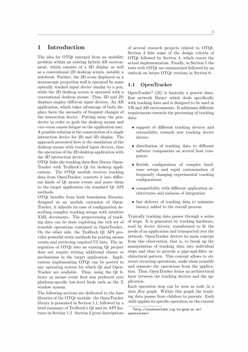
The Rockin’ Mouse presented in [1] was a fourdegree-of-freedom (DOF) input device that hadthe same shape as a regular mouse, but wasrounded at the bottom so that it could be ti-tled. By tilting it about the x and z axes, theRockin’ Mouse added two more DOF to the reg-ular mouse. The authors presented advantagesof the regular mouse in detail: accurate as itoperates on a flat horizontal surface letting thegrip variable (precise or “lazy” for wider cur-sor movements), little fatiguing as the operat-ing arm rests on the table, precise because theheavy design does dampen the user’s tremor,relative positioning starting from the point ofengagement, natural mapping of mouse motionto mouse cursor and not the least: the huge fa-miliarity of users with it. The major drawbackof the classic mouse was, that it did not support3D operations. Some methods existed to en-able 3D manipulation: keyboard modifier keyswere used to switch between movement in thethree axes, or the 3D object was displayed withmouse-selectable axis and plane “manipulators”
7
Figure 4: The Rockin’ Mouse can be tiltedleft/right resp front/back (not shown here)adding two additional degrees of freedom to theclassic mouse (images taken from [1]).
permitting to move the object along the selectedaxis (1D movement) or on the selected plane (2Dmovement). However, the major problem of theclassic mouse remained: it did not allow to per-form a 3D translation task in one integral move-ment. Instead, at least two separate movementoperations were needed.Consequently the Rockin’ Mouse was designedto inherit the advantages of the regular mouseand adding the capability of performing trans-lation operations in one turn by performing tilt-ing and planar movements of the mouse concur-rently. An extensive evaluation test was per-formed, which compared the Rockin’ Mouse tothe classic mouse in context of a 3D object po-sitioning task. The task was to move an objectwithin a virtual 3D scene from one corner to theother. Results showed, that the test subjectswere 30 % faster with the Rockin’ Mouse.
Summary
The first project presented features a conversionof 3D tracking interactions events into 2D ap-plication mouse events in order to synchronizevirtual and “real” (2D) contents by renderingthe virtual scene with bitmaps captured fromtheir 2D counterparts. The conversion of track-ing data into 2D application mouse events is oneof the major issues of OTQt.ErgoDesk experiments with transistions be-tween stereoscopic and monoscopic view on atable-sized workbench. A tracked 3D prop actsas switch trigger depending on whether the de-vice is over the desk or not. In order to calculatethat condition, incoming tracking coordinatesfrom the 3D prop must be converted to work-bench desk coordinates. The desk coordinatesystem is determined in a prepending calibra-tion routine. OTQt also performs a calibrationstep in order to determine the spatial locationof 2D desktop screens within the tracking coor-
dinate system.The interaction on large surfaces as describedtakes place in front of or even directly on largeprojection or video walls. The cursor position iscalculated from the user’s hands directing at orknocking on the desired spot, thus manipulatinga sensible volume or plane. OTQt deals with thesimulation of the desktop mouse by measuringthe cursor position of tracked devices which areconducted in a sensible volume in front of thedesktop screen.The Rockin’ Mouse is an input device that canbe used to execute 2D and 3D tasks. It is actu-ally one possibility to overcome the introducedusability problem by matching the interactiondevices of 2D and 3D display. While OTQt triesto simulate the desktop mouse with 3D interac-tion devices, the Rockin’ Mouse goes the oppo-site direction extending a typical 2D interactiondevice to work in 3D applications.
3 Requirements
OTQt is part of the OpenTracker frameworkand forms a OpenTracker module. The pur-pose of the OTQt module is the simulationof a desktop mouse by generating appropriatemouse events from tracking data, typically post-ing events to a Qt desktop application. The fol-lowing number of requirements outline the de-sign of OTQt:Integration into (existing) Qt projects. OTQtshould be integrable as easy as possible, ideallywith a few lines of code at a central point in theQt code. The mouse events should be deliveredto any kind of GUI widget without restrictions(including the 3D graphics OpenGL extensionsof Qt). OTQt should provide a shared libraryinstalled in an operating system’s default librarypath so target applications can link with them.Customization of input devices. The numberand kind of employed devices should be keptvariable. For any subtask (mouse move, but-ton event generation) OTQt allows the use ofdifferent input devices providing tracking data.OTQt should specify input data format spec-ifications which must be fulfilled. For exam-ple, 3-DOF position data from a pen-like de-vice could be configured as basis for mouse moveevents, foot switch data could be used in orderto generate mouse button events, eye trackingdata could be employed generating mouse wheelevents. OTQt as part of OpenTracker inherits
8
its powerful XML configuration features allow-ing many kinds of setups.Desktop application screen calibration. In or-der to compute the correct intersection locationof tracked input devices on the target applica-tion desktop screen, the dimensions of the screensurface must be computed in advance. OTQtshould provide a tool for performing such cali-brations quick and easy.Low processing overhead and thread-safety.OTQt should add a minimum of processing andmemory overhead to the application. Due tothe expensive busy-waiting nature of the Open-Tracker main loop, OTQt should implement anown main loop body method which is called byone less-expensive timer thread. The code ofthe main loop body executed each cycle mustbe thread-safe.Build environment. OTQt should use the same- GNU autotools - build environment as Open-Tracker regarding future integration with Open-Tracker. GNU autotools fulfill the requirementof multi-platform availabilty ([13]).
4 Implementation
The analysis of the Qt API in Section 1.2.1yields the required input data for the generationof all necessary mouse events. As stated in therequirements, the user should be able to spec-ify different tracking data input devices for eachsubtask. In the following, the possible devicesare listed:
• Mouse Position Device (MPD) Pro-vides spatial 3D position data for the calcu-lation of the desktop mouse cursor position(3-DOF device).
• Mouse Button Device (MBD) Providesbutton state values either enabled or dis-abled for each button at a time, at least theleft, right and middle mouse button.
• Mouse Wheel Device (MWD) Provideswheel state values either enabled or disabledfor wheel forward and backward rotation.
OTQt requires another tracked device in orderto compute the relation between MPD positiondata and desktop screen coordinates:
• Application Screen Position Device(ASPD) Provides 3D position and orienta-tion of the target applicaton desktop screen(6-DOF device).
To separate between tracking devices, eachsource device receives a corresponding Open-Tracker sink node where the tracking devicedata is linked to. OTQt implements the follow-ing sink nodes as classes derived from a commonbase class QtMouseEventSinkBase:
• Application Screen Position Sink (ASPS)class QtAppScreenPosSink
• Mouse Position Sink (MPS)class QtMousePosSink
• Mouse Button Sink (MBS)class QtMousePosSink
• Mouse Wheel Sink (MWS)class QtMouseWheelSink
OTQt requires the ASPS, MPS and MBS to besupplied with tracking data, while the MWS re-mains optional and can be left out if no mousewheel events are desired. One and the sametracked device can be employed as multifunc-tional device acting as data source for severalsinks. As an example, one device can act asMPD and MBD concurrently by transmittingthe device data into the corresponding sinks(MPS and MBS).Tracking events in OpenTracker are instances ofclass State providing several fixed-typed pub-lic member variables which contain data suchas position and orientation. The member vari-able button encodes button states in a binarystring. According to its type unsigned short,the button variable features 16 slots, each repre-senting the state of one button. Actually, mostof the OpenTracker nodes only use the first eightslots. The mapping between the event buttonstring and Qt buttons implemented in the MBSlooks the following:
Slot Qt Button Id0 Qt::LeftButton1 Qt::RightButton2 Qt::MidButton
3-7 not used
A button is considered as “pressed” if the cor-responding slot bit is equal to 1, otherwise thebutton is considered as “released”. The MWSalso uses the button member of the State eventclass and maps slots to wheel events as follows.A wheel move is indicated by a binary slot valueof 1.
9
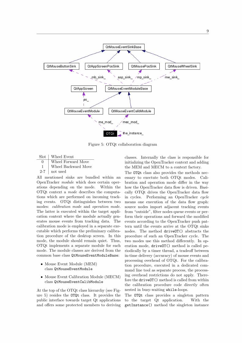
Figure 5: OTQt collaboration diagram
Slot Wheel Event0 Wheel Forward Move1 Wheel Backward Move
2-7 not usedAll mentioned sinks are bundled within anOpenTracker module which does certain oper-ations depending on the mode. Within theOTQt context a mode describes the computa-tions which are performed on incoming track-ing events. OTQt distinguishes between twomodes: calibration mode and operation mode.The latter is executed within the target appli-cation context where the module actually gen-erates mouse events from tracking data. Thecalibration mode is employed in a separate exe-cutable which performs the preliminary calibra-tion procedure of the desktop screen. In thismode, the module should remain quiet. Thus,OTQt implements a separate module for eachmode. The module classes are derived from thecommon base class QtMouseEventModuleBase:
• Mouse Event Module (MEM)class QtMouseEventModule
• Mouse Event Calibration Module (MECM)class QtMouseEventCalibModule
At the top of the OTQt class hierarchy (see Fig-ure 5) resides the OTQt class. It provides thepublic interface towards target Qt applicationsand offers some protected members to deriving
classes. Internally the class is responsible forinitializing the OpenTracker context and addingthe MEM and MECM to a context factory.The OTQt class also provides the methods nec-essary to exectute both OTQt modes. Cali-bration and operation mode differ in the wayhow the OpenTracker data flow is driven. Basi-cally OTQt drives the OpenTracker data flowin cycles. Performing an OpenTracker cyclemeans one execution of the data flow graph:source nodes import adjacent tracking eventsfrom “outside”, filter nodes queue events or per-form their operations and forward the modifiedevents according to the OpenTracker push pat-tern until the events arrive at the OTQt sinksnodes. The method driveOT() abstracts theprocedure of such an OpenTracker cycle. Thetwo modes use this method differently. In op-eration mode, driveOT() method is called pe-riodically by a timer thread, a tradeoff betweenin-time delivery (accuracy) of mouse events andprocessing overhead of OTQt. For the calibra-tion procedure, executed in a dedicated com-mand line tool as separate process, the process-ing overhead restrictions do not apply. There-fore the driveOT() method is called from withinthe calibration procedure code directly oftennested in busy-waiting while-loops.The OTQt class provides a singleton patternto the target Qt application. With thegetInstance() method the singleton instance
10
can be retrieved from any point in Qt code al-lowing the access of the OTQt class public inter-face. The triggerMEM() method abstracts theinitialization and startup of OTQt reducing theeffort of implementation within a Qt applicationto one line of code.To encounter the requirement of easy config-uration, a three step configuration proce-dure is introduced. In the first step OTQt pro-vides a template XML configuration file and thecorresponding XML Document Type Defintion(DTD) file. In the second step the user is en-couraged to edit the XML file template accociat-ing actual devices to the single sinks. Basically,tracking source nodes need to be specified toseveral well-identified references (ASPD, MPD,MBD, MWD), which undertake the task of for-warding the data to the corresponding sinks. Ifnecessary, the entire bandwidth of OpenTrackernodes is available to the user in order to ap-ply preprocessing operations on tracking de-vice data to fulfill the sink data specifications.The editing is achieved by either using a simpletext editor or a more sophisticated XML edi-tor where syntactical and semantical support isprovided on basis of the DTD. The result of thesecond step is a intermediate XML configura-tion file which lacks the results from the cali-bration routine. Thus, the third and final stepconsists of the execution of the OTQt calibra-tion tool providing the intermediate XML file-name as input argument. The command-linecalibration tool imports the file performing abasic syntax check. Evident errors, for exam-ple missing mandatory device definitions are re-ported. The purpose of the calibration tool isto determine the spatial location and extent ofthe target application desktop screen relative tothe location and orientation of the ASPD. Thetool edits the specified intermediate configura-tion file adding the computed data from the cal-ibration and prints the resulting final XML fileeither as console output or to a specified file des-tination.
4.1 Calibration mode
The calibration mode is applied during thecalibration routine. The purpose of the cal-ibration routine is to calculate and store thelocation and extent of the target applicationscreen relative to the position and orientationof the tracked 6-DOF ASPD. OTQt providesthe otqt-mem-calib command line tool, which
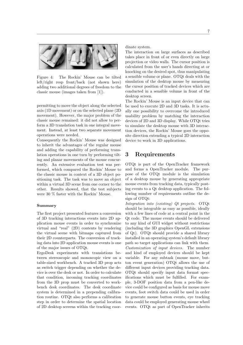
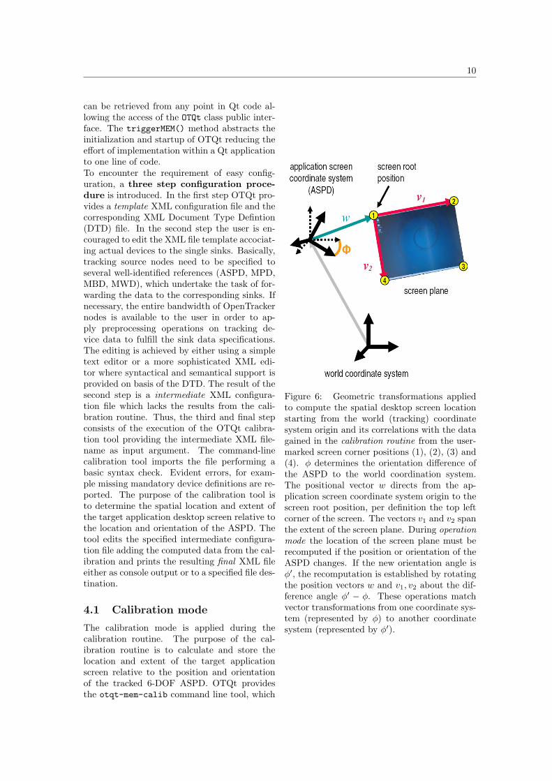
Figure 6: Geometric transformations appliedto compute the spatial desktop screen locationstarting from the world (tracking) coordinatesystem origin and its correlations with the datagained in the calibration routine from the user-marked screen corner positions (1), (2), (3) and(4). φ determines the orientation difference ofthe ASPD to the world coordination system.The positional vector w directs from the ap-plication screen coordinate system origin to thescreen root position, per definition the top leftcorner of the screen. The vectors v1 and v2 spanthe extent of the screen plane. During operationmode the location of the screen plane must berecomputed if the position or orientation of theASPD changes. If the new orientation angle isφ′, the recomputation is established by rotatingthe position vectors w and v1, v2 about the dif-ference angle φ′ − φ. These operations matchvector transformations from one coordinate sys-tem (represented by φ) to another coordinatesystem (represented by φ′).
11
guides the user through the calibration proce-dure. The procedure is implemented in classMEMCalibProc derived from OTQt.The tool is called with an intermediate Open-Tracker/OTQt XML configuration file as argu-ment as proposed in the three-step configura-tion procedure. The given configuration file isedited, thus the results of the calibration arewritten to the file resulting in a final, applicableversion. otqt-mem-calib demands the givenXML file to contain a valid data flow graph andspecifications of the external sources (tracked in-put devices) assigned to OTQt sink nodes. An-other mandatory condition is the existance ofan QtMouseEventCalibConfig element nestedin the XML <configuration> section. Thetools performs a basic syntax check to validatethese assumptions.Following, the OpenTracker context is initial-ized parsing the input configuration file. Oncethis has been done, the tool performs sometracking tests on the specified devices. It willnot continue, if it does not perceive ASPD, MPDand MBD correctly.From the user’s perspective the core calibra-tion procedure consists of marking the four cor-ner points of the target desktop screen startingfrom top left corner continuing clockwise: topleft, top right, bottom right, bottom left. Eachcorner is marked by guiding the MPD towardsthe requested point, and once ready, the userhas to press one button of the MBD signalizingthat the desired destination has been reached.Consequently the tool traces the position of theMPD. The marked corner position must remainstable within some threshold region while theMPD button is requested to stay pressed forabout two seconds. If the MPD position leavesthe threshold region during that period, for ex-ample due to trembling of the user’s hand, thetwo seconds timer is restarted. Releasing thebutton also resets the timer. Otherwise, the toolrecognizes the corner point as marked, and con-tinues with the next corner point. After the lastcorner has been marked the calibration data iscomputed. Figure 6 illustrates the calibrationroutine and the explains the gained geometri-cal data. The entire routine is resistant againstchanges of the ASPD position and orientationduring the calibration, thus the location of thedesktop screen (or notebook) can be altered ar-bitrarily.In the last step, the given XML configurationfile is edited. The QtMouseEventCalibConfig
Value XML attribute nameφ CSOrientationQuatw CSRoot2ScreenRootVecv1 ASWidthVecv2 ASHeightVec
Table 1: Calibration values and their XML at-tribute names. The values w, v1 and v2 areVectors in R3 and φ is an angle represented asquaternion quadruple ([3]).
element is replaced with a QtMouseEventConfigelement. The nested QtAppScreen config nodecontains the attributes (see Table 1) which storethe calibration data.
4.2 Operation mode
The operation mode describes the actual mouseevent generating procedure of OTQt. It as-sumes, that the OTQt configuraton steps havebeen successfully performed. A final XML con-figuration file was produced and a OTQt hookwas implemented in the target Qt application.With the start of the Qt application the OTQtmodule is initalized and started.The initialization startup takes place in mem-ber methods of the OTQt class: the OpenTrackercontext is initalized, the OTQt modules objectsare created and added to context factories, theprovided XML configuration file is parsed, theMEM is initialized and generates the appropri-ate sink objects. Finally a timer thread usingthe Qt class QTimer is initialized with a defaulttimeout of 20 milliseconds calling the driveOT()method at the end of each timeout performingone OpenTracker cycle.The design principle concerning sinks and mod-ules is the following: The sinks are kept rather“stupid” as they basically store copies of incom-ing events. Some sinks provide simple but use-ful methods which indicate changes in trackingevent data. Most of the work is done in themodule (MEM) itself: the application screen 3Dlocation management, the mouse cursor place-ment and the generation of button and wheelevents. There main reason for that design de-cision is simple: only in the module all infor-mation is available to decide wheater certain Qtmouse events should be generated or not.The OTQt sinks store incoming events only ifthe pending event differs from the last eventwhich was processed in the MEM. Each sink

12
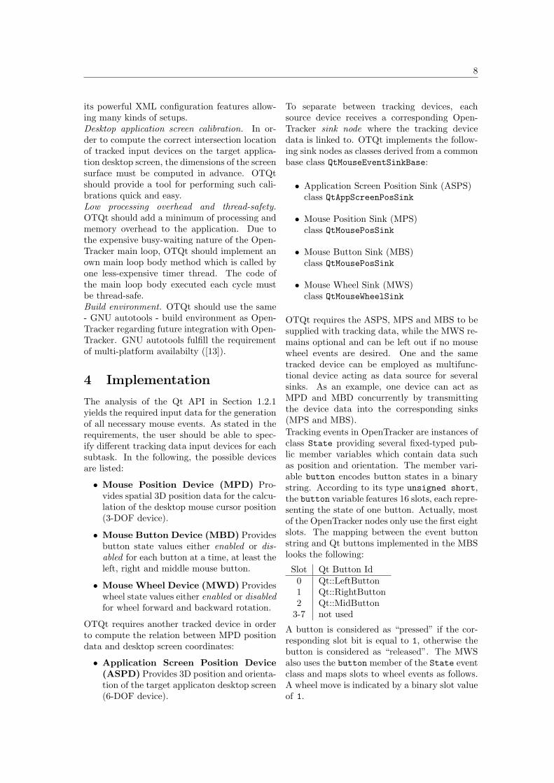
Figure 7: The screen cuboid is spanned by thescreen width v1, screen height v2 and screendepth v3. v3 is computed as dot product ofv1×v2. The volume marks the mouse event sen-sitive region. That means: only while the MPD(displayed here as pen) actually intersects thescreen coboid volume, the OTQt module willgenerate and post mouse events. In this case,the MPD position is converted into correspond-ing desktop coordinates and OTQt will post aMouseMove event to the Qt applicaton, where-upon the correct mouse cursor position is set.
employs a two element event queue internally,which stores the current and the previous event.If the pending event differs from the currentevent, the event is copied and stored as newcurrent event while the old current event be-comes the previous event. The original event ispassed unchanged to parent nodes of the sink.The intention of this early event filtering is thereduction of computational load. Only relevantevents are processed afterwards in the module.Each sink indicates the arrival of a new eventby enabling the pending event dirty bit.The pending event flag is the signal for the mod-ule that a sink provides a new, unseen track-ing event. The main processing method ofthe MEM is the pullState() method whichis triggered from within the OpenTracker cyclemethod driveOT() after all sinks received theirevents and could set their flag.The processing of pending events starts withthe ASPS. The MEM employs a separate classQtAppScreen which provides methods to updatethe geometric information about the location ofthe desktop screen in case the ASPD changedits position and/or orientation (see Figure 6).Without accurate information about the loca-
tion and extent of the desktop screen, the secondstep, the computation of the mouse cursor co-ordinates would be impossible. OTQt defines acertain 3D volume located in front of the targetdesktop screen as mouse event sensible region.This region is called screen cuboid (SC). Figure7 illustrates this concept.The consequent flow of the procedure mainlydepends on whether the MPD resides inside oroutside the SC. If it is outside, the module in-structs the sinks to refuse tracking events forthe duration of the MPD residing outside theSC and quits. At the time the MPD reentersthe SC this blockade is annulated. If the MPDresides inside the SC, the MPD position is usedto update the desktop cursor coordinate. Ona desktop coordinate change a MouseMove Qtevent is created.Next, regarding the MBS, the current and pre-vious event of each mouse button (typically left,right and middle button) are compared, search-ing for bit transitions which indicate eitherMouseButtonPress or MouseButtonReleaseevents. To detect the special case of aMouseDoubleClick event, which is generatedif the event triple press, release, press occurswithin a certain time frame, the MEM recordsthe latest mouse press and release event togetherwith their timestamps in a dedicated data struc-ture.The generation of mouse wheel events also baseson the comparison of current and previous eventwithin the MWS. Certain bit transitions in-dicate either a Wheel Forward Move or WheelBackward Move expressed by a positive or neg-ative delta value in the Qt mouse wheel event.At the end of the pullState() method the gen-erated events collected in lists are posted tothe target Qt application using the non-blockingpostEvent() method, which takes Qt event ob-ject pointers as argument. The deallocation ofthe heap objects is done by Qt. At any point thepullState() method exits, the pending eventflags of all sinks are reset.
5 Results
The OTQt test environment consisted of atablet notebook, the optical A.R.T. trackingsystem and several tracked devices. The note-book was equipped with a 14 inches (≈ 35 cm)diameter display featuring a resolution of 1400x 1050 pixel, an Intel Pentium M 1.80 GHz pro-

13
cessor and 1.5 GB of main memory. The opticalA.R.T. tracking system as described in SectionA.1 can be considered as very accurate examin-ing the performance Table 2. For the tracking ofthe notebook position and orientation a specialtracking target (ASPD) was constructed.The processing overhead of OTQt will be de-scribed as CPU usage percentage reported bythe Unix shell tool top. The same action wasperformed once with OTQt enabled and oncenot (using the desktop mouse) on a target Qt ap-plication. Observations showed, that the targetapplication CPU usage share on the test note-book increased between 5 % and 10 % when usedtogether with OTQt.Using OTQt, mouse cursor speed and accuracycan be described as good. With a thread time-out less or equal 50 ms wide, mouse movementsover the whole screen are displayed without anyannoying delay. The accuracy of the mouse cur-sor depends heavily on the following parameters:
• accuracy of the tracking system in gen-eral, and expecially concerning the opti-cal A.R.T. system if not all tracking targetmarkers are visisble
• accuracy of the MPD head calibration
• accuracy of the OTQt display screen cali-bration
Each of the above parameters influences theaccuracy performance considerably. The noise(jitter) of the tracking system itself is less aproblem since it is filtered in OTQt by simplethresholding. However, imprecise spatial screencorner positions make it impossible to computeaccurate desktop cursor coordinates from track-ing data. Bad calibration of the MPD head af-terwards causes the mouse cursor to bop aroundeven if the MPD is hold still.The behaviour of user interfaces in conjunc-tion with OTQt was tested by implementingthe OTQt module into some target Qt appli-cations such as displayed in Figure 8. The desk-top mouse behaviour on and with the Qt UIswas studied and tests for OTQt were derived.The tests comprised of basic tests such as sin-gle mouse button press and release actions andmore advanced tests mainly concerning drag-and-drop behaviour.UI actions controlled with single mouse buttonclicks (mouse button press and release events)
(a) SoQt Examiner (b) File icon viewer
Figure 8: With the SoQt examiner, the follow-ing mouse behaviour was tested: clicking leftand right mouse buttons selected toolbar iconsor opened context menus. Mouse move eventscaused mouse-over sensitive menus to pop up.To operate the perspective sliders, the conjunc-tion of mouse press and mouse move events wastested. The geometric object shown in the mainpanel was moved with mouse clicks and mousemoves. The tests with the file icon viewer werefocused on drag-and-drop features: a set of iconscan be marked with rectangular frames dragedby the mouse (mouse move and press events inconjunction). The selection can be draged andreleased on one of the directories (displayed astree elements in the left panel) in order to sim-ulate a file copy operation. Directory contentswere displayed on the right panel after double-clicking a directory element.
and mouse double clicks worked good when gen-erated by OTQt events. Mouse-over behaviourof certain widgets, such as framing of toolbaricons or menu popups, also worked. Some ac-tions, which are the result of mouse buttonpress events and mouse move events, such asthe manipulation of a scrollbar were performedas expected. Surprisingly, drag-and-drop oper-ations, which basically require the same mouseevent combinations, did not work at all until thethread timeout was descreased from 50 ms to20 ms. Then, drag-and-drop worked much bet-ter, but still not 100 % reliable. Drag-and-dropoperations tested were for example: marking aset of icons with an extendable frame, dragingthe same icon set over the desktop and onto adrop responsive widget receiving the appropri-ate action. Mouse wheel events performed asexpected: both forward and backward moves,shifting content vertically and horizontally, weretested successfully.

14
6 Conclusions and FutureWork
In this article I presented OTQt, an Open-Tracker module extension which converts datafrom dedicated tracked input devices into mouseevents, which are posted to Qt desktop appli-cations. OTQt performs accurate and conformwith reference behaviour of the desktop mousein many ways. The mouse cursor behaviour isaccurate, simple mouse clicking events work asexpected. Still, there is work to do. Tasks suchas drag-and-drop do not work in a reliable man-ner, others do not work at all. Amongst theseare such as putting the keyboard cursor in atextfield by clicking on it or closing an openedcombobox by clicking on a different location out-side.Currently, other developers work on Open-Tracker 1.2 whose central new feature will bethe support of multi-modal events. The cur-rent static event data structure will be replacedin favour of C++ template based event objects([10]). The integration of OTQt with Open-Tracker 1.2 is actually discussed. The next ver-sion of OTQt (probably as part of OpenTracker)should then be a generally revised and exhaus-tively tested version of the current one. Be-sides the fixing of the evident problems, morefeatures should be implemented. One exampleare keyboard modifiers of mouse events, that isthe concurrent press of keys such as ctrl or shiftand mouse buttons. OTQt also wants to switchfrom Qt3 to its sucessor Qt version 4, which pro-vides new and richer interfaces, which for exam-ple make the keyboard modifier feature feasible([12]).
A AR Environment
This chapter describes the augmented reality en-vironment where the OTQt module was devel-opped and tested.The environment consists of a stereoscopic largescreen projection system and an optical trackingsystem. The system is currently designed for asingle head-tracked user wearing shutter glassesin order to compute and perceive the convenient3D images. The major application running onthe system is the virtual liver surgery planningsystem (VLSP) described in [2] which is builton top of the AR framework Studierstube ([9]).The OpenTracker data-flow library is employed
position orientation[mm] [deg]
accuracy absolute 0.4 0.12repeatability 0.06 0.03maximum error 1.4 0.4noise 0.03 0.015
Table 2: Tracking accuracy of the A.R.T. sys-tem. The results describe the tracking of a 6-DOF target employed in a tracking area of 3 m x3 m observed with four cameras. All the targetmarkers were fully visible throughout the testperiod (table taken from [5]).
as middleware between the tracking system andStudierstube.In the coming Section A.1 the optical trackingsystem A.R.T. is described, followed by SectionA.2 presenting the tracked devices relevant forOTQt.
A.1 Tracking System
The A.R.T. infrared optical tracking system([5]) is capable of tracking the position (threecoordinates) and/or orientation (three indepen-dent angular coordinates) of bodies (subjects orobjects). The body is equipped with a contact-less target consisting of several retroreflectivespherical or flat circular markers. The trackingcameras emit infrared light flashes periodicallyinto the measuring volume. The light is reflectedby each hit marker. Each cameras capture thereflected light, compute each marker’s local 2Dcoordinates and send the coordinates to a track-ing server over the ethernet network. Figure 9shows a target and a camera of the A.R.T. sys-tem. The number of cameras employed in a sys-tem ranges from two to 36. The used system isequipped with four of them.The cameras are connected over ethernet net-work via a switch to a central tracking PC.The camera synchronization is done via sepa-rate BNC connections between the PC and thecameras. On the tracking PC the A.R.T. soft-ware DTrack is running, which controls the en-tire tracking system (see Figure 10 for a setupoverview). DTrack receives two DOF markercoordinates from the cameras and calculates theposition of single markers (3-DOF) or bodies (6-DOF) relative to the measuring volume coordi-nate system.In order to gain a measuring volume, the room

15
Figure 9: On the left side a 6-DOF target withmarkers and right the tracking camera equippedwith infraread LED’s, CCD sensors and outgo-ing ethernet cables (image taken from [5]).
where the tracking system is located must becalibrated once at installation time. Each newtarget introduced in the system must also becalibrated. Both tasks can be done with func-tionality and interfaces provided by DTrack.Finally, DTrack sends the computed 6-DOFoutput coordinates in binary or ASCII encod-ing to some configurable UDP ports and hosts,where the data can be fetched by interestedparties. Some interface software packages ex-ist, which can be used as link between DTrackand the target application: Trackd, VRPN,VR Juggler and OpenTracker. In the ac-tual setup OpenTracker is used as middleware.DTrack/OpenTracker uses the second networkcard installed on the tracking PC to offer thetracking data to other software components ondifferent hosts.
A.2 Tracked Input Devices
The following images show the tracked inputdevices which were employed in the AR envi-ronment during the tests of the OTQt mod-ule. Figure 11 shows the tracking target used totrack the position and orientation of the note-book. Figure 12 shows the source devices forbutton resp wheel events (MBD, MWD) andmove events (MPD). The head of the MPD wascalibrated with the A.R.T. DTrack software.
Figure 10: The basic A.R.T. setup: camerastrack markers of targets, reporting 2D coordi-nates over the ethernet network to a tracker PCwhere DTrack software is running. DTrack syn-chonizes the cameras over BNC connections andcalculates the target’s position and orientation.The output data is propagated over the secondnetwork device (image taken from [5]).
Figure 11: Application Screen Position Device(ASPD) mounted on a notebook.

16
Figure 12: Left: Mouse Button and WheelDevice (MBD, MWD) aka Eye-of-Ra. Right:Mouse Position Device (MPD).
B Installation
This section briefly describes the workflow whencompiling and installing the OTQt package onthe system. Throughout this guide, shell com-mands are denoted with a “$>” prefix. As cur-rent working directory the base directory of theOTQt source package is assumed, except whereexplizitely given.
Install prerequisites
OTQt requires the prior installation of the fol-lowing software packages. Please refer to the in-stallation instructions of the respective packagefor details.
• OpenTracker library version 1.1: avail-able from http://studierstube.icg.tu-graz.ac.at/opentracker/download/
• Trolltech Qt library of the 3.3 se-ries: free edition available fromhttp://www.trolltech.com/download/opensource.html
• GNU autotools (other versions may workbut were not tested) autoconf 2.5, au-tomake 1.9: available from http://www.gnu.org/
Bootstrap
This step can be omitted, if a convenient GNUautotools configure script already exists forthe current operation system platform. Other-wise the configure script must be generatedwith the following command:
$> ./bootstrap
Configure
The actual build system is examined by theconfigure script. The script can be exten-sively parametrized by specifying command lineswitches. Amongst others, the location of theexternal foundation libraries OpenTracker andTrolltech Qt3 can be manually set with thequoted switches below.
$> ./configure--with-opentracker=<DIR>--with-qtdir=<DIR>
Compile and Install
After the successful completion of the config-ure procedure, the OTQt source package can becompiled and installed with the following com-mands:
$> make$> make install
Most probably, the installation command mustbe executed with root/administrator permis-sions. On Linux systems, the different partsof the OTQt package are installed into the fol-lowing destination directories, using the defaultprefix /usr/local (the prefix is customizablevia configure).
/usr/local/bin: Binaries such as calibration tool./usr/local/lib: The shared library./usr/local/include/OTQt: The C++ header files./usr/local/share/OTQt: Shared data such as template XMLfile and DTD file.
C Configuration
This section describes the configuration work-flow for the usage of the OTQt module togetherwith a desktop Qt application. In the subse-quent section an overview of the workflow isgiven followed by a section which contains moredetailed information about the single configura-tion steps.
C.1 Overview
1. Copy XML template and DTD filesCopy template otqt-mem-config-template.xml andopentracker.dtd from the OTQt data directory to theexecution directory of the target Qt application.
$> cp /usr/local/share/OTQt/* <QT_APP_LOCATION>
2. Edit XML template fileModify the copied template XML file or create an in-termediate configuration file from scratch. Describethe tracking environment as OpenTracker data flowgraph. Link tracking data sources to the OTQt sinks.

17
3. Calibrate desktop screenExecute the calibration routine providing the inter-mediate file in order to generate a final XML config-uration file.
$> otqt-mem-calib -o final.xml intermediate.xml
4. Implement OTQt hook in Qt applicationImplement OTQt in the target Qt application mainmethod (using public static methods from the OTQtclass interface) providing the final configuration fileas argument.
OTQt::triggerMEM("final.xml")
5. Compile the Qt application with OTQtExtend the build environment by specifying specialcompiler and linker flags for OTQt. Compile the Qtapplication.
INCLUDEPATH += $${OTQT_DIR}/includeLIBS += -L$${OTQT_DIR}/lib -lOTQt
6. Start the Qt application with OTQt
C.2 Details
Copy XML template and DTD files
To ease the creation of a valid Open-Tracker/OTQt XML configuration file, OTQtprovides a template XML configuration file andthe corresponding DTD file. The mentionedfiles reside in the /usr/local/share/OTQt di-rectory if OTQt was installed as described inthe previous section. The DTD file must be putin the execution directory of the target Qt ap-plication, where OpenTracker will try to find itat startup. Without the appropriate DTD file,OpenTracker will fail to parse the XML config-uration file.
$> cp /usr/local/share/OTQt/* <QT_APP_LOCATION>otqt-mem-config-template.xml -> <QT_APP_LOCATION>opentracker.dtd -> <QT_APP_LOCATION>
Edit XML template file
The copied template XML file must be cus-tomized according to the actual tracking sys-tem. External sources must be specified, whichsupply data to the OTQt sinks. Other Open-Tracker nodes can be used to manipulate theexternal data to fit the interface specificationsof the OTQt sinks. The template configurationfile looks like this:
<?xml version="1.0" encoding="UTF-8"?><!DOCTYPE OpenTracker SYSTEM "opentracker.dtd"><OpenTracker>
<configuration><!-- (I) Mouse Event (Calibration) Module
configuration --><QtMouseEventCalibConfig />
</configuration>
<!-- (II) Tracking Device Source Section --><TODOUnknownSource DEF="AppScreenPositionDevice" /><TODOUnknownSource DEF="MousePositionDevice" /><TODOUnknownSource DEF="MouseButtonDevice" /><TODOUnknownSource DEF="MouseWheelDevice" />
<!-- (III) Sink Section --><QtAppScreenPosSink>
<Ref USE="AppScreenPositionDevice" /></QtAppScreenPosSink><QtMousePosSink>
<Ref USE="MousePositionDevice" /></QtMousePosSink><QtMouseButtonSink>
<Ref USE="MouseButtonDevice" /></QtMouseButtonSink><QtMouseWheelSink>
<Ref USE="MouseWheelDevice" /></QtMouseWheelSink>
</OpenTracker>
The template file is kept very simple, designedin a such a way that the user only has to insertproper external tracking data sources in (II),which are then redirected to the OTQt sinksin (III). One and the same tracking device canbe redirected to different sinks in (III) as wellas manipulation nodes can be applied to prepro-cess (merge, filter) the incoming tracking events.The template file can be edited arbitrarily creat-ing more complex data flow graphs. Exception:the line after (I) must remain unedited, sincethis line is expected to look exactly that way inthe subsequent calibration routine. The result-ing XML file of this step is called intermediateand may look like this:
<!-- [..] -->
<!-- (II) Tracking Device Source Section --><NetworkSource number="12" DEF="ASPD" /><NetworkSource number="9" DEF="MousePositionDevice" /><NetworkSource number="20" DEF="MouseButtonDevice" /><!-- (A) device not specified --><!-- <TODOUnknownSource DEF="MouseWheelDevice" /> -->
<!-- (III) Sink Section --><!-- [..] --><QtMouseButtonSink>
<Ref USE="MouseButtonDevice" /></QtMouseButtonSink><QtMouseWheelSink>
<!-- (B) device reused --><Ref USE="MouseButtonDevice" />
</QtMouseWheelSink>
<!-- [..] -->
Here, the source data for the sinks arrives overthe network at the specified NetworkSourcenodes in (II). With the number attribute, dif-ferent streams for ASPD, MPD, MBD are dis-tinguished. Note, that no explizit MWD sourcefor the MWS is specified (A), rather the MPDsupplies the data to the MWS in (B).

18
Calibrate desktop screen
The intermediate XML configuration file lacksthe results from a calibration routine of thetarget application desktop screen. The pro-vided OTQt calibration tool for that purposeis started from command line providing onemandatory argument, the filename of a validand compliant input configuration file, for exam-ple the intermediate configuration file describedbefore. With the optional “-o” flag the user mayspecify the output XML filename. By default,the output is printed to console.
$> otqt-mem-calib -o final.xml intermediate.xml
The calibration tool does syntax-check thegiven input OTQt configuration file. Errors oc-curing during the parsing of the file are reportedto console by OpenTracker. Once the Open-Tracker context has been established success-fully, the tool performs tracking tests with themandatorily specified devices ASPD, MPD andMBD. If all of these devices are perceived cor-rectly the calibration routine is entered. Oth-erwise the tool quits with an appropriate errormessage.The calibration routine asks the user to markthe four corners of the target applicationdesktop screen in the following sequence: topleft, top right, bottom right, bottom left.Each screen corner is detected over the positionof the MPD. The user has to direct the MPDto the desired position and press the “left” but-ton of the MBD. The corner is recognized bythe tool after the MPD position remained sta-ble for more than two seconds and the “left”button remained pressed throughout that time.If the MPD position leaves a certain thresholdregion during the measurement time, the timeris restarted. Releasing the “left” MPD buttonalso resets the timer.Once all four corner points of the desktop screenhave been marked, the tool computes the cal-ibration data, edits the input XML file andprints the resulting output XML file eitherto console or to the specified output destinationfile. The edited parts of the returned XML filelook the following:
<!-- [..] --><configuration>
<!-- (I) Mouse Event (Calibration) Moduleconfiguration -->
<QtMouseEventConfig><!-- (A) Calibration Data Element --><QtAppScreen
ASHeightVec="0.0000 -0.9999 0.0000"
ASWidthVec="0.9999 0.0000 0.0000"CSOrientationQuat="0.0000 0.0000 -0.7071 0.7071"CSRoot2ScreenRootVec="-0.9999 -0.9999 0.0000"
/></QtMouseEventConfig>
</configuration><!-- [..] -->
The QtMouseEventCalibConfig XML elementis replaced with a QtMouseEventConfig elementin (I). The nested QtAppScreen element (A)contains attributes which store the computedcalibration data.Summing, the OTQt calibration tool convertsan intermediate XML file into a final OTQt con-figuration file, applicable in the target Qt appli-cation.
Implement OTQt hook in Qt application
The OTQt public interface provides somestatic methods which abstract the initializationstartup of OTQt and are designed to be imple-mented in Qt application main methods:
#include "mainwindow.h"#include <qapplication.h>/* (A) Include OTQt header */#include <OTQt/OTQt.h>
int main( int argc, char ** argv ){
QApplication a( argc, argv );MainWindow w;a.setMainWidget(&w);w.show();
/* (B) Initialize/Start Mouse Event Module */if (!OTQt::triggerMEM("final.xml"))
return -1;
return a.exec();}
The integration is done by including the OTQt.hheader file in (A) and using the static wrappermethod in (B) passing the final XML configura-tion file obtained from the calibration tool.
Compile the Qt application with OTQt
In order to successfully compile the Qt applica-tion with OTQt, the Qt application build filesmust be extended if the OpenTracker and/orOTQt header files and libraries have been in-stalled to a non-system-default location. As-suming, that the Qt application developer em-ploys qmake as Makefile generator, the follow-ing lines should be included into the applicationproject files, adding the necessary compiler andlinker flags:
# (I) Specify Installation PathsOTQT_DIR = /non/default/install/directory/OTQt

19
OPENTRACKER_DIR = /somewhere/OpenTracker# (II) Add Compiler + Linker FlagsINCLUDEPATH += $${OPENTRACKER_DIR}/include/OpenTrackerINCLUDEPATH += $${OTQT_DIR}/includeLIBS += -Wl,-rpath -Wl,$${OTQT_DIR}/libLIBS += -L$${OTQT_DIR}/lib -lOTQt
Start the Qt application with OTQt
After compilation, the Qt application can bestarted. The OTQt module is started automati-cally together with the application providing themouse event generating services.
References
[1] Ravin Balakrishnan, Thomas Baudel, Gor-don Kurtenbach, and George W. Fitzmau-rice. The rockin’ mouse: Integral 3D ma-nipulation on a plane. In CHI, pages 311–318, 1997.
[2] A. Bornik, R. Beichel, B. Reitinger,G. Gotschuli, E. Sorantin, F. Leberl, andM. Sonka. Computer aided liver surgeryplanning: An augmented reality approach.In SPIE Medical Imaging ’03, pages 395–405. February 2003.
[3] Erik B. Dam, Martin Koch, and MartinLillholm. Quaternions, interpolation andanimation. Technical report, Departmentof Computer Science, University of Copen-hagen, July 1998.
[4] Andrew S. Forsberg, Joseph J. Laviola, andRobert C. Zeleznik. Ergodesk: A frame-work for two- and three-dimensional inter-action at the activedesk, May 20 1998.
[5] Augmented Reality Tracking GmbH.A.R.T. system, February 2006. online atwww.ar-tracking.de.
[6] Joseph A. Paradiso. Several sensor ap-proaches that retrofit large surfaces for in-teractivity. September 2002.
[7] Holger Regenbrecht, Gregory Baratoff, andMichael Wagner. A tangible AR desk-top environment. Computers & Graphics,25(5):755–763, 2001.
[8] Gerhard Reitmayr and Dieter Schmalstieg.OpenTracker – A flexible software designfor three dimensional interaction. Vir-tual Reality, Springer, London, 9(1):79–92,2005.
[9] Dieter Schmalstieg, Anton Fuhrmann,Gerd Hesina, Zsolt Szalavari, L. Miguel En-carnacao, Michael Gervautz, and WernerPurgathofer. The Studierstube augmentedreality project. Technical report, ViennaUniversity of Technology, 2002.
[10] Dieter Schmalstieg, Gerhard Reitmayr, andJoseph Newman. Multi-modal events inOpenTracker 1.2. 2005.
[11] Trolltech. Qt 3.3 whitepaper. online atwww.trolltech.com.
[12] Trolltech. Qt 4.0 whitepaper. online atwww.trolltech.com.
[13] Gary V. Vaughan, Ben Elliston, TomTromey, and Ian Lance Taylor. GNU Au-toconf, Automake, and Libtool. Sams, 1stedition, October 2000.