Other Products · 2019-10-04 · Other Products 429 Catalog Number of KHK Stock Gears Material Type...
8
Other Products 429 Catalog Number of KHK Stock Gears Material Type S S45C RT Pawls and Ratchets GC Gear Coupling V Involute Spline Other Products S V 20 - 200 Total Length (200 mm) Major Diameter (20 mm) Type (Involute spline shafts) Material (S45C) The Catalog Number for KHK stock gears is based on the simple for- mula listed below. Please order KHK gears by specifying the Catalog Numbers. (Example) Spur Gears Helical Gears Internal Gears Racks CP Racks & Pinions Miter Gears Bevel Gears Screw Gears Worm Gear Pairs Bevel Gearboxes Other Products GCU Gear Assembly Kit Page 438 SV/SVI Involute Spline Shafts, Spline Bushings m1.667 Page 436 Heat Treatment: Thermal refined Material: S45C SRT/SRT-C Ratchets & Pawls P2.09 ~ 12.57 Page 430 Material: S45C Series Heat Treatment: Gear teeth induction hardened SRTB/SRT-C Ratchets & Pawls P2.09 ~ 12.57 Page 432 Material: S45C Series Heat Treatment: Gear teeth induction hardened GC/GC-I Gear Couplings m2, 2.5 Page 434 Material: S45C Heat Treatment: Gear teeth induction hardened DLS Rack & Pinion Lubrication System Page 440 New
Transcript of Other Products · 2019-10-04 · Other Products 429 Catalog Number of KHK Stock Gears Material Type...

Other Products
429
Catalog Number of KHK Stock Gears
Material TypeS S45C RT Pawls and Ratchets
GC Gear CouplingV Involute Spline
Other Products
S V 20 - 200Total Length (200 mm)Major Diameter (20 mm)Type (Involute spline shafts)
Material (S45C)
The Catalog Number for KHK stock gears is based on the simple for-mula listed below. Please order KHK gears by specifying the Catalog Numbers. (Example)
Sp
urG
ears
Hel
ical
Gea
rsIn
tern
alG
ears
Rac
ksC
P R
acks
& P
inio
nsM
iter
Gea
rsB
evel
Gea
rsS
crew
Gea
rsW
orm
Gea
r P
airs
Bev
elG
earb
oxes
Oth
erP
rod
ucts
GCUGear Assembly Kit
Page 438
SV/SVIInvolute Spline Shafts, Spline Bushings
m1.667 Page 436
Heat Treatment: Thermal refinedMaterial: S45C
SRT/SRT-CRatchets & Pawls
P2.09 ~ 12.57 Page 430
Material: S45C
Series
Heat Treatment: Gear teeth induction hardened
SRTB/SRT-CRatchets & Pawls
P2.09 ~ 12.57 Page 432
Material: S45C
Series
Heat Treatment: Gear teeth induction hardened
GC/GC-IGear Couplings
m2, 2.5 Page 434
Material: S45CHeat Treatment: Gear teeth
induction hardened
DLSRack & Pinion Lubrication System
Page 440
New

430 431
Sp
urG
ears
Hel
ical
Gea
rsIn
tern
alG
ears
Rac
ksC
P R
acks
& P
inio
nsM
iter
Gea
rsB
evel
Gea
rsS
crew
Gea
rsW
orm
Gea
r P
airs
Bev
elG
earb
oxes
Oth
erP
rod
ucts
Sp
urG
ears
Hel
ical
Gea
rsIn
tern
alG
ears
Rac
ksC
P R
acks
& P
inio
nsB
evel
Gea
rsS
crew
Gea
rsW
orm
Gea
r P
airs
Bev
elG
earb
oxes
Oth
erP
rod
ucts
Mite
rG
ears
Please see our web site for corrections on KHK Catalogs.
Ratchets
Allowable torque (N・m) Allowable torque (kgf・m) Weight
(kg)Bending strength Bending strength
3.074.10 6.00 7.118.24
0.310.420.610.730.84
0.0350.0530.0960.120.15
14.7 19.5 29.4 34.5 39.4
1.501.993.003.524.02
0.160.240.440.560.70
29.0 49.2 70.8 94.3
2.965.027.229.61
0.280.530.851.24
92.6 158 229
9.4416.123.3
0.861.582.54
226 385 559
23.039.357.0
1.893.535.66
PawlsPitch 2.09~ 12.57SRT-C
I
E
A DH
J
T4
Specifications
Angle of teeth 60°
Material S45C
Heat treatment Induction hardened teeth
Tooth hardness 50~ 60HRC
Surface treatment Black oxide coating
Specifications
Angle of teeth 60°
Material S45C
Heat treatment Induction hardened teeth
Tooth hardness 50~ 60HRC
Surface treatment Black oxide coating
Catalog No. Shape K (L) M (N) PWeight
(kg)SRT2/3-CSRT1-CSRT2-CSRT3-CSRT4-C
T5
58
101213
(8)(10)(12.5)(15)(18)
3039556580
(38)(49)(67.5)(80)(98)
612152025
0.0200.0570.130.230.38
Catalog No. PitchNo. of teeth
ShapeBore Hub dia. Outside dia. Face width Hub width Total length Depth of teeth Center distance Mounting distance
A B D E F G H I J
SRT2/3-50SRT2/3-60SRT2/3-80SRT2/3-90SRT2/3-100
2.09
50608090
100
T4
1010121212
―
33.34053.36066.6
6 ― 6 1
33.8435.5139.4841.7344.11
15.671925.672932.33
SRT1-50SRT1-60SRT1-80SRT1-90SRT1-100
3.14
50608090
100
T4
1215151515
―
50608090
100
12 ― 12 1.6
45.4848.2454.7358.3562.16
23.428.438.443.448.4
SRT2-30SRT2-40SRT2-50SRT2-60
6.28
30405060
T4
15151515
―
6080
100120
15 ― 15 3.1
61.2366.2372.2879.14
26.936.946.956.9
SRT3-30SRT3-40SRT3-50
9.42304050
T4152020
―90
120150
20 ― 20 576.3285.1595.52
405570
SRT4-30SRT4-40SRT4-50
12.57304050
T4202020
―120160200
25 ― 25 7.495.74
108.03122.37
52.672.692.6
(N)
M
K
P
(L)60° FD
T5* FD has die-forged finish.
RatchetsPitch 2.09~ 12.57SRT
① Due to the gear teeth being induction hardened, no secondary operations can be performed on tooth areas including the bottom land (approx. 2 to 3 mm).
〔Caution on Product Characteristics〕
[Caution on Secondary Operations]
① Regarding SRTB ratchets with hubs, please note the direction of teeth, viewed from the hub side. KHK can produce ratchets that have teeth pointed in the opposite direction as a custom order item.
① The pawls are designed to prevent reverse rotation. They are not suitable for use as driving ratchets or driving rotation.
② SRT2/3-C is manufactured using a lost wax casting method.
〔Caution on Product Characteristics〕
Pawls
SRT-C
SRT
Bore Keyway Js9
Screw sizeCatalog No.
10 12 14 15 16 17 18 19 20 22 25 28 30 32 35 40 45 504 × 1.8 5 × 2.3 6 × 2.8 8 × 3.3 10 × 3.3 12 × 3.3 14 × 3.8
―SRT2/3-50 J BORE T4K T4K T4K
SRT2/3-60 J BORE T4K T4K T4K T4K T4K T4K T4K
SRT2/3-80 J BORE T4K T4K T4K T4K T4K T4K T4K T4K T4K
SRT2/3-90 J BORE T4K T4K T4K T4K T4K T4K T4K T4K T4K T4K
SRT2/3-100 J BORE T4K T4K T4K T4K T4K T4K T4K T4K T4K T4K T4K T4K
SRT1-50 J BORE T4K T4K T4K T4K T4K T4K T4K T4K
SRT1-60 J BORE T4K T4K T4K T4K T4K T4K T4K T4K
SRT1-80 J BORE T4K T4K T4K T4K T4K T4K T4K T4K T4K T4K T4K
SRT1-90 J BORE T4K T4K T4K T4K T4K T4K T4K T4K T4K T4K T4K T4K
SRT1-100 J BORE T4K T4K T4K T4K T4K T4K T4K T4K T4K T4K T4K T4K T4K
SRT2-30 J BORE T4K T4K T4K T4K T4K T4K T4K
SRT2-40 J BORE T4K T4K T4K T4K T4K T4K T4K T4K T4K T4K T4K
SRT2-50 J BORE T4K T4K T4K T4K T4K T4K T4K T4K T4K T4K T4K T4K T4K
SRT2-60 J BORE T4K T4K T4K T4K T4K T4K T4K T4K T4K T4K T4K T4K T4K T4K
SRT3-30 J BORE T4K T4K T4K T4K T4K T4K T4K T4K T4K T4K T4K T4K
SRT3-40 J BORE T4K T4K T4K T4K T4K T4K T4K T4K T4K
SRT3-50 J BORE T4K T4K T4K T4K T4K T4K T4K T4K T4K
SRT4-30 J BORE T4K T4K T4K T4K T4K T4K T4K T4K T4K
SRT4-40 J BORE T4K T4K T4K T4K T4K T4K T4K T4K T4K
SRT4-50 J BORE T4K T4K T4K T4K T4K T4K T4K T4K T4K
Series
I
E
A DH
J
T4K
[Caution on J series] ① As available-on-request products, requires a lead-time for shipping within 2 working-days (excludes the day ordered), after placing an order. Please allow additional shipping time to get to your local distributor.② Number of products we can process for one order is 1 to 20 units. For quantities of 21 or more pieces, we need to quote price and lead time.③ Keyways are made according to JIS B1301 standards, Js9 tolerance.④ Areas of products which have been re-worked will not be black oxide coated.
To order J Series products, please specify; Catalog No. + J + BORE* The product shapes of J Series items are identified by background color.
■ Bending Strength of RatchetsThe allowable transmission force Fb (N) of ratchets is the value calculated by the following formula.
Also, the SRT Ratchet's allowable torque (TN・m) for bending strength is calculated by the following formula.
Where
Fb = σb・ b・e2
6 ・ ・1h
1SF
: Bending stress Assumed 225.55MPa (23kgf/mm2): Face width mm Dimension Table ratchet face width E: Root length mm
: Depth of teeth mm Dimension Table ratchet tooth depth H: Safety factor Assumed 2: Tooth root radius m
σb
be
hSF
rf
■ Application
Example: ratchets used for complete reverse prevention of worm gears
RatchetsRatchet Pawls
T = Fb・rf
* The illustration is a design example, not a design for machinery or a device in actual use.
e = h x tan 360
No. of teeth
60 - is the calculation
rf =Outside dia. D - 2h
2000
■ Features of Pawls and Ratchets● A simple structure used to restrict the rotational direction in one-way. ● The tips of pawls and the teeth of ratchets are induction hardened and therefore have superior durability.

432 433
Sp
urG
ears
Hel
ical
Gea
rsIn
tern
alG
ears
Rac
ksC
P R
acks
& P
inio
nsM
iter
Gea
rsB
evel
Gea
rsS
crew
Gea
rsW
orm
Gea
r P
airs
Bev
elG
earb
oxes
Oth
erP
rod
ucts
Sp
urG
ears
Hel
ical
Gea
rsIn
tern
alG
ears
Rac
ksC
P R
acks
& P
inio
nsB
evel
Gea
rsS
crew
Gea
rsW
orm
Gea
r P
airs
Bev
elG
earb
oxes
Oth
erP
rod
ucts
Mite
rG
ears
Please see our web site for corrections on KHK Catalogs.
Allowable torque (N・m) Allowable torque (kgf・m) Weight
(kg)Bending strength Bending strength
3.07 4.10 6.00 7.11 8.24
0.310.420.610.730.84
0.0670.100.160.210.24
14.7 19.5 29.4 34.5 39.4
1.501.993.003.524.02
0.240.340.610.730.87
29.0 49.2 70.8 94.3
2.965.027.229.61
0.470.821.141.59
92.6 158 229
9.4416.123.3
1.402.173.22
226 385 559
23.039.357.0
2.754.386.72
PawlsPitch 2.09~ 12.57SRT-C
Specifications
Angle of teeth 60°
Material S45C
Heat treatment Induction hardened teeth
Tooth hardness 50~ 60HRC
Surface treatment Black oxide coating
Specifications
Angle of teeth 60°
Material S45C
Heat treatment Induction hardened teeth
Tooth hardness 50~ 60HRC
Surface treatment Black oxide coating
Catalog No. Shape K (L) M (N) PWeight
(kg)SRT2/3-CSRT1-CSRT2-CSRT3-CSRT4-C
T5
58
101213
(8)(10)(12.5)(15)(18)
3039556580
(38)(49)(67.5)(80)(98)
612152025
0.0200.0570.130.230.38
Catalog No. PitchNo. of teeth
ShapeBore Hub dia. Outside dia. Face width Hub width Total length Depth of teeth Center distance Mounting distance
A B D E F G H I J
SRTB2/3-50SRTB2/3-60SRTB2/3-80SRTB2/3-90SRTB2/3-100
2.09
50608090
100
T9
1010121212
2530354040
33.34053.36066.6
6 10 16 1
33.8435.5139.4841.7344.11
15.671925.672932.33
SRTB1-50SRTB1-60SRTB1-80SRTB1-90SRTB1-100
3.14
50608090
100
T9
1215151515
3540505050
50608090
100
12 12 24 1.6
45.4848.2454.7358.3562.16
23.428.438.443.448.4
SRTB2-30SRTB2-40SRTB2-50SRTB2-60
6.28
30405060
T9
15151515
50606065
6080
100120
15 14 29 3.1
61.2366.2372.2879.14
26.936.946.956.9
SRTB3-30SRTB3-40SRTB3-50
9.42304050
T9152020
758085
90120150
20 16 36 576.3285.1595.52
405570
SRTB4-30SRTB4-40SRTB4-50
12.57304050
T9202020
9090
100
120160200
25 18 43 7.495.74
108.03122.37
52.672.692.6
(N)
M
K
P
(L)60° FD
T5* FD has die-forged finish.
RatchetsPitch 2.09~ 12.57SRTB
① Due to the gear teeth being induction hardened, no secondary operations can be performed on tooth areas including the bottom land (approx. 2 to 3 mm).
[Caution on Product Characteristics]
[Caution on Secondary Operations]
① Regarding SRTB ratchets with hubs, please note the direction of teeth, viewed from the hub side. KHK can produce ratchets that have teeth pointed in the opposite direction as a custom order item.
② Due to heat treating, some deformation of the bore may occur. It may be necessary to ream the bore to bring to the stated dimensions.
① The pawls are designed to prevent reverse rotation. They are not suitable for use as driving ratchets or driving rotation.
② SRT2/3-C is manufactured using a lost wax casting method.
〔Caution on Product Characteristics〕
Ratchets
A B D
I
J
H
E FG
T9
Pawls
SRT-C
SRTB
Bore Keyway Js9
Screw sizeCatalog No.
10 12 14 15 16 17 18 19 20 22 25 28 30 32 35 40 45 504 × 1.8 5 × 2.3 6 × 2.8 8 × 3.3 10 × 3.3 12 × 3.3 14 × 3.8
―
Series
A B D
I
J
H
E FG
K
T9K
SRTB2/3-50 J BORE T9K
SRTB2/3-60 J BORE T9K T9K T9K T9K T9K
SRTB2/3-80 J BORE T9K T9K T9K T9K T9K T9K
SRTB2/3-90 J BORE T9K T9K T9K T9K T9K T9K T9K T9K
SRTB2/3-100 J BORE T9K T9K T9K T9K T9K T9K T9K T9K
SRTB1-50 J BORE T9K T9K T9K T9K T9K T9K
SRTB1-60 J BORE T9K T9K T9K T9K T9K T9K
SRTB1-80 J BORE T9K T9K T9K T9K T9K T9K T9K T9K T9K
SRTB1-90 J BORE T9K T9K T9K T9K T9K T9K T9K T9K T9K
SRTB1-100 J BORE T9K T9K T9K T9K T9K T9K T9K T9K T9K
SRTB2-30 J BORE T9K T9K T9K T9K T9K T9K T9K T9K T9K
SRTB2-40 J BORE T9K T9K T9K T9K T9K T9K T9K T9K T9K T9K T9K
SRTB2-50 J BORE T9K T9K T9K T9K T9K T9K T9K T9K T9K T9K T9K
SRTB2-60 J BORE T9K T9K T9K T9K T9K T9K T9K T9K T9K T9K T9K
SRTB3-30 J BORE T9K T9K T9K T9K T9K T9K T9K T9K T9K T9K T9K T9K T9K
SRTB3-40 J BORE T9K T9K T9K T9K T9K T9K T9K T9K
SRTB3-50 J BORE T9K T9K T9K T9K T9K T9K T9K T9K T9K
SRTB4-30 J BORE T9K T9K T9K T9K T9K T9K T9K T9K T9K
SRTB4-40 J BORE T9K T9K T9K T9K T9K T9K T9K T9K T9K
SRTB4-50 J BORE T9K T9K T9K T9K T9K T9K T9K T9K T9K
[Caution on J series] ① As available-on-request products, requires a lead-time for shipping within 2 working-days (excludes the day ordered), after placing an order. Please allow additional shipping time to get to your local distributor.② Number of products we can process for one order is 1 to 20 units. For quantities of 21 or more pieces, we need to quote price and lead time.③ Keyways are made according to JIS B1301 standards, Js9 tolerance.④ Certain products which would otherwise have a very long tapped hole are counterbored to reduce the length of the tap.⑤ Areas of products which have been re-worked will not be black oxide coated.⑥ For products having a tapped hole, a set screw is included.
To order J Series products, please specify; Catalog No. + J + BORE* The product shapes of J Series items are identified by background color.
K = Half of hub length (F)
■ Application
Example: ratchets used for complete reverse prevention of worm gears
RatchetsRatchet Pawls
* The illustration is a design example, not a design for machinery or a device in actual use.
■ Bending Strength of RatchetsThe allowable transmission force Fb (N) of ratchets is the value calculated by the following formula.
Also, the SRT Ratchet's allowable torque (TN・m) for bending strength is calculated by the following formula.
Where
Fb = σb・ b・e2
6 ・ ・1h
1SF
: Bending stress Assumed 225.55MPa (23kgf/mm2): Face width mm Dimension Table ratchet face width E: Root length mm
: Depth of teeth mm Dimension Table ratchet tooth depth H: Safety factor Assumed 2: Tooth root radius m
σb
be
hSF
rf
T = Fb・rf
e = h x tan 360
No. of teeth
60 - is the calculation
rf =Outside dia. D - 2h
2000
■ Features of Pawls and Ratchets● A simple structure used to restrict the rotational direction in one-way. ● The tips of pawls and the teeth of ratchets are induction hardened and therefore have superior durability.
434 435
Sp
urG
ears
Hel
ical
Gea
rsIn
tern
alG
ears
Rac
ksC
P R
acks
& P
inio
nsM
iter
Gea
rsB
evel
Gea
rsS
crew
Gea
rsW
orm
Gea
r P
airs
Bev
elG
earb
oxes
Oth
erP
rod
ucts
Sp
urG
ears
Hel
ical
Gea
rsIn
tern
alG
ears
Rac
ksC
P R
acks
& P
inio
nsB
evel
Gea
rsS
crew
Gea
rsW
orm
Gea
r P
airs
Bev
elG
earb
oxes
Oth
erP
rod
ucts
Mite
rG
ears
Please see our web site for corrections on KHK Catalogs.
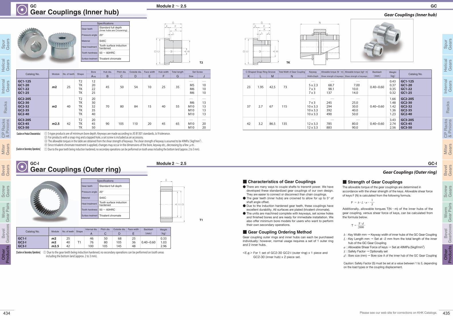
Gear Couplings (Inner hub)
Gear Couplings (Outer ring)
G
BD C
FEK
AM
JL
TK
Gear Couplings (Inner hub)GC
Gear Couplings (Outer ring)Module 2~ 2.5
Module 2~ 2.5
GC-I
G
BD C
FEK
AM
L
T2
E
A C D
T1
Specifications
Gear teeth Standard full depth(Inner hubs are Crouwning)
Pressure angle 20°
Material S45C
Heat treatment Tooth surface induction hardened
Tooth hardness 50~ 60HRC
Surface treatment Trivalent chromate
Catalog No. Module No. of teeth ShapeBore Hub dia. Pitch dia. Outside dia. Face width Hub width Total length Set Screw
A H8 B C D E F G Size J
GC1-12SGC1-20GC1-22GC1-25
m2 25
T2TKTKTK
12202225
45 50 54 10 25 35
―M5M6M6
―101010
GC2-20SGC2-30GC2-32GC2-35GC2-40
m2 40
T2TKTKTKTK
2030323540
70 80 84 15 40 55
―M6
M10M10M10
―13131313
GC3-20SGC3-45GC3-50
m2.5 42T2TKTK
204550
90 105 110 20 45 65―
M10M10
―2020
Catalog No. Module No. of teeth ShapeInternal dia. Pitch dia. Outside dia. Face width Backlash
(mm)Weight
(kg)A C D E
GC1-IGC2-IGC3-I
m2m2m2.5
254042
T14676
100
5080
105
68105145
253648
0.40~0.600.331.032.96
① S-type products are of minimum bore depth. Keyways are made according to JIS B1301 standards, Js 9 tolerance.② For products with a snap ring and a tapped hole, a set screw is included as an accessory.③ The allowable torques in the table are obtained from the shear strength of keyways. The shear strength of keyway is assumed to be 49MPa(5kgf/mm2).④ Since trivalent-chromate treatment is applied, changes may occur in the dimensions of the bore, keyway etc., decreasing by a few μm .
〔Caution on Product Characteristics〕
① Due to the gear teeth being induction hardened, no secondary operations can be performed on tooth areas including the bottom land (approx. 2 to 3 mm).
[Caution on Secondary Operations]
C-Shaped Snap Ring Groove Total Width of Gear Coupling Keyway Allowable torque (N・m) Allowable torque (kgf・m) Backlash
(mm)Weight
(kg)Catalog No.
K L M N Width×Depth Shear strength of keyways Shear strength of keyways
23 1.95 42.5 73
―5 x 2.37 x 37 x 3
―68.7 98.1
137
―7.00
10.0 14.0
0.40~0.60
0.430.370.350.32
GC1-12SGC1-20GC1-22GC1-25
37 2.7 67 115
―7 x 3
10 x 3.310 x 3.310 x 3.3
―245 294 392 490
―25.0 30.040.050.0
0.40~0.60
1.661.481.421.361.23
GC2-20SGC2-30GC2-32GC2-35GC2-40
42 3.2 86.5 135―
12 x 3.312 x 3.3
―785 883
―80.090.0
0.40~0.603.432.742.56
GC3-20SGC3-45GC3-50
N
[Caution on Secondary Operations]
GC-I
GC
Specifications
Gear teeth Standard full depth
Pressure angle 20°
Material S45C
Heat treatment Tooth surface induction hardened
Tooth hardness 50~ 60HRC
Surface treatment Trivalent chromate
① Due to the gear teeth being induction hardened, no secondary operations can be performed on tooth areas including the bottom land (approx. 2 to 3 mm).
■ Gear Coupling Ordering MethodGear coupling outer rings and inner hubs can each be purchased individually: however, normal usage requires a set of 1 outer ring and 2 inner hubs.
<E.g.> For 1 set of GC2-30 GC2-I (outer ring) x 1 piece and GC2-30 (inner hub) x 2 piece set.
■ Characteristics of Gear Couplings● There are many ways to couple shafts to transmit power. We have
developed these standardized gear couplings of our own design. They are easier to connect or disconnect than chain couplings.
● The gear teeth (inner hubs) are crowned to allow for up to 5° of shaft angle offset.
● Due to the induction hardened gear teeth, these couplings have excellent durability. All surfaces are plated (trivalent chromate).
● The units are machined complete with keyways, set screw holes and finished bores and are ready for immediate installation. We also offer minimum bore models for users who want to perform their own secondary operations.
■ Strength of Gear CouplingsThe allowable torque of the gear couplings are determined in accordance with the shear strength of the keys. Allowable shear force of keys F (N) is calculated from the following formula.
Additionally, allowable torques T(N・m) of the inner hubs of the gear coupling, versus shear force of keys, can be calculated from the formula below.
F = b・L・σ・1S
: Key Width mm Keyway width of inner hubs of the GC Gear Coupling: Key Length mm Set at -2 mm from the total length of the inner hub of the GC Gear Coupling
: Allowable Shear Force of keys Set at 49MPa (5kgf/mm2): Safety Factor Optionally set: Bore size (mm) Bore size A of the inner hub of the GC Gear Coupling
bL
σSd
Caution: Safety Factor (S) must be set at a value between 1 to 3, depending on the load types or the coupling displacement.
T = F・d2000
436 437
Sp
urG
ears
Hel
ical
Gea
rsIn
tern
alG
ears
Rac
ksC
P R
acks
& P
inio
nsM
iter
Gea
rsB
evel
Gea
rsS
crew
Gea
rsW
orm
Gea
r P
airs
Bev
elG
earb
oxes
Oth
erP
rod
ucts
Sp
urG
ears
Hel
ical
Gea
rsIn
tern
alG
ears
Rac
ksC
P R
acks
& P
inio
nsB
evel
Gea
rsS
crew
Gea
rsW
orm
Gea
r P
airs
Bev
elG
earb
oxes
Oth
erP
rod
ucts
Mite
rG
ears
Please see our web site for corrections on KHK Catalogs.
Involute Spline Bushings
GE F
Dd
TB
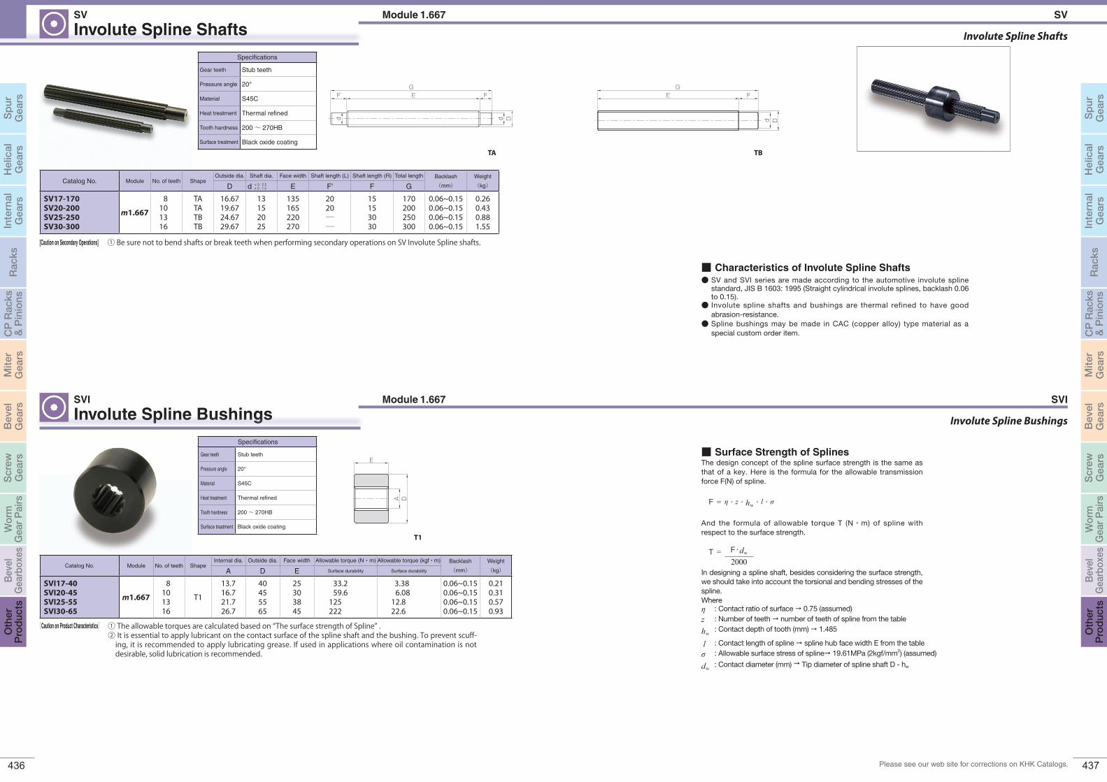
Involute Spline ShaftsModule 1.667SV
Involute Spline BushingsModule 1.667SVI
d D
GEF’ F
d
TA
E
A D
T1
Specifications
Gear teeth Stub teeth
Pressure angle 20°
Material S45C
Heat treatment Thermal refined
Tooth hardness 200~ 270HB
Surface treatment Black oxide coating
Specifications
Gear teeth Stub teeth
Pressure angle 20°
Material S45C
Heat treatment Thermal refined
Tooth hardness 200~ 270HB
Surface treatment Black oxide coating
Catalog No. Module No. of teeth ShapeOutside dia. Shaft dia. Face width Shaft length (L) Shaft length (R) Total length Backlash
(mm)
Weight
(kg)D d E F' F G
SV17-170SV20-200SV25-250SV30-300
m1.667
8101316
TA TATBTB
16.6719.6724.6729.67
13152025
135165220270
2020――
15153030
170200250300
0.06~0.150.06~0.150.06~0.150.06~0.15
0.260.430.881.55
Catalog No. Module No. of teeth ShapeInternal dia. Outside dia. Face width Allowable torque (N・m) Allowable torque (kgf・m) Backlash
(mm)
Weight
(kg)A D E Surface durability Surface durability
SVI17-40SVI20-45SVI25-55SVI30-65
m1.667
8101316
T1
13.716.721.726.7
40455565
25303845
33.2 59.6
125 222
3.38 6.08
12.8 22.6
0.06~0.150.06~0.150.06~0.150.06~0.15
0.210.310.570.93
① Be sure not to bend shafts or break teeth when performing secondary operations on SV Involute Spline shafts.[Caution on Secondary Operations]
+ 0 . 2 5+ 0 . 1 5
〔Caution on Product Characteristics〕 ① The allowable torques are calculated based on “The surface strength of Spline” . ② It is essential to apply lubricant on the contact surface of the spline shaft and the bushing. To prevent scuff-
ing, it is recommended to apply lubricating grease. If used in applications where oil contamination is not desirable, solid lubrication is recommended.
SVI
Involute Spline Shafts
SV
■ Characteristics of Involute Spline Shafts● SV and SVI series are made according to the automotive involute spline
standard, JIS B 1603: 1995 (Straight cylindrical involute splines, backlash 0.06 to 0.15).
● Involute spline shafts and bushings are thermal refined to have good abrasion-resistance.
● Spline bushings may be made in CAC (copper alloy) type material as a special custom order item.
■ Surface Strength of SplinesThe design concept of the spline surface strength is the same as that of a key. Here is the formula for the allowable transmission force F(N) of spline.
F = η・z・hw・l・σ
And the formula of allowable torque T (N・m) of spline with respect to the surface strength.
T =
In designing a spline shaft, besides considering the surface strength, we should take into account the torsional and bending stresses of the spline. Where
: Contact ratio of surface 0.75 (assumed): Number of teeth number of teeth of spline from the table: Contact depth of tooth (mm) 1.485
: Contact length of spline spline hub face width E from the table: Allowable surface stress of spline 19.61MPa (2kgf/mm2) (assumed)
: Contact diameter (mm) Tip diameter of spline shaft D - hw
ηzhw
lσdw
F・dw
2000

438 439
Sp
urG
ears
Hel
ical
Gea
rsIn
tern
alG
ears
Rac
ksC
P R
acks
& P
inio
nsM
iter
Gea
rsB
evel
Gea
rsS
crew
Gea
rsW
orm
Gea
r P
airs
Bev
elG
earb
oxes
Oth
erP
rod
ucts
Sp
urG
ears
Hel
ical
Gea
rsIn
tern
alG
ears
Rac
ksC
P R
acks
& P
inio
nsB
evel
Gea
rsS
crew
Gea
rsW
orm
Gea
r P
airs
Bev
elG
earb
oxes
Oth
erP
rod
ucts
Mite
rG
ears
Gear Assembly Kit (For use in learning about gears)GCU
GCU-R GCU-S
GCU-W
GCU-N
GCU-M
100mm
100mm
100mm
GCU-H
With sticker
GC
Photo shows GCU-RAssembly Procedure Details are available online
→ → →
→
Remove protective sheet Insert bushing Set in shaft
Adhere the sticker and it’s complete!
Screw-fasten
Assemble into frame
Photo shows GCU-R
Set Contents
→
■ Features of GearCube
● Assembly kits can be connected flexibly.● The frame is made of polycarbonate with high transparency
and impact resistance.● Gears combine MC nylon and metal, making lubrication unnecessary.● An instruction manual is included, enabling easily assembly by anyone.
See the gears with your own eyes and move them with your own hands to learn about their mechanisms and characteristics.
This product is certified by KAWAGUCHI i-mono i-waza
* These kits are not for actual use to transmit power. Please use only as representations of gear systems.
Hand Wheel GCU-H45
Optional
Gear Cube
GCU
GCU-N Screw Gear Kit
Screw Gears are helical gears used in nonpar-allel and nonintersecting situations. Applica-tions include devices like conveyers with light loads.
GCU-W Worm Gear Pair Kit
Worm Gear Pairs can be used to make large reductions in speed in a single phase. The worm gear cannot be driven by the worm wheel due to inherent self-locking.
All six types of assembly kit and input/output shafts can be con-nected.
Installation: Nonparallel and nonintersecting gearsGear Type: Worm Gear PairGears: SW2-R1
PG2-20R1Gear Ratio: 20Weight: Approx. 1kg
GCU-S Spur Gear Kit
The Gear Kit contains a two-stage spur gear train and allows speed increases / reductions, and includes the most commonly used com-binations of gears.
GCU-H Helical Gear Kit
Helical gears have more strength than spur gears of the same dimensions and have the advantage of being less noisy.
Installation: Parallel Axes (Two-stage)
Gear Type: Spur GearsGears: 2 units of SS1.5-16
2 units of PS1.5-22Gear Ratio: 1.89Weight: Approx. 1kg
Installation: Parallel AxesGear Type: Helical Gears
(also for Screw Gears)
Gears: SN2.5-10L PN2.5-10R
Gear Ratio: 1Weight: Approx. 1kg
GCU-M Miter Gear Kit
Use of bevel gears allows the changing of the shaft angle by 90 degrees. Applications in-clude the changing of the direction of power.
GCU-R Rack Kit
Use of racks enables the conversion of rota-tion motion to linear motion. Applications in-clude devices that provide lift.
Installation: Parallel AxesGear Type: Racks &
PinionsGears: SRO1.5-500
PS1.5-20Weight: Approx. 1kg
Installation: Intersecting AxesGear Type: Miter GearsGears: SM2-25
PM2-25Gear Ratio: 1Weight: Approx. 1kg
Installation: Nonparallel and nonintersecting gearsGear Type: Screw GearsGears: SN2.5-10R
PN2.5-10RGear Ratio: 1Weight: Approx. 1kg

440 441
Sp
urG
ears
Hel
ical
Gea
rsIn
tern
alG
ears
Rac
ksC
P R
acks
& P
inio
nsM
iter
Gea
rsB
evel
Gea
rsS
crew
Gea
rsW
orm
Gea
r P
airs
Bev
elG
earb
oxes
Oth
erP
rod
ucts
Sp
urG
ears
Hel
ical
Gea
rsIn
tern
alG
ears
Rac
ksC
P R
acks
& P
inio
nsB
evel
Gea
rsS
crew
Gea
rsW
orm
Gea
r P
airs
Bev
elG
earb
oxes
Oth
erP
rod
ucts
Mite
rG
ears
Please see our web site for corrections on KHK Catalogs.
● Application Examples
Rack & Pinion Lubrication SystemDLS Schmiersysteme
■ System Configuration
■ Features
NO. Product Name
1 Flex pump
2 Grease cartridge
3 Tube connector
4 Tube
5 Mounting shaft
6 Lubricating gear
V=5 m/s
V=4 m/s
V=3 m/s
V=2 m/s
V=1 m/s
20.1
0.2
0.3
0.4
0.5
0.60.70.80.91.0
2.0
3.0
4.0
3 4 5 6 8 10 12
Module
Req
uire
d am
ount
of l
ubric
ant (
cm³/
24h)
● Ideal lubrication system for racks & pinions used in open environments.● A small amount of grease extruded from the pump is automatically supplied through the lubri-
cating gear.● Integration is possible with the control system of the machine in use, to adjust the amount of lu-
bricant* according to the application.● Grease is applied by a polyurethane lubricating gear to form a uniform lubricating film.● Grease up to consistency No. 3 can be used regardless of the manufacturer.● Special grease GC-F01 does not drip or pollute the machine.● Optimized lubricant improves the durability of racks & pinions and reduces the maintenance costs.
* Please use the required amount of lubricant in Table 1 as a guide depending on the module of the product used and the peripheral speed (m/S).
Table 1. Required amount of lubricant
4
5
3
6
1
3
2
196
33.5 M12x1
96 3088
94112
Φ6.6(2x)
107
111
Rack & Pinion Lubrication Systems
Flex pump
Flex pump
24 VDC automatic time controlled lubrication pump
FP400
FP400B
3 V battery automatic time controlled lubrication pump
Specifications
Dimensions (W x H x D) Max: 112 x 196 x 94 mm
Weight (no lubricant) 1120 g
Operation method Piston pump type
Lubricating oil amount 400cm3
Lubricant supply amount 0.15 cm3/pulse
Operating pressure Up to 70 bar
Lubricant Grease of consistency up to NLGI No. 3
Operating temperature -25 to 70°C
Number of outlets 1 port
How to connect pipes Tube T-6 x 4, available up to 10 m
Operating voltage 24 VDC (battery type is 3 V)
Consumption voltage (24 VDC) Imax ≤ 350 mA
Mounting direction Omni-directional mounting available
Control device Built-in, electronic type
Pressure monitor Built-in, electronic type
Lubricant level monitor Built-in, lead contact type
Malfunction signal Error detection / grease depletion, back pressure rise, etc.
Dustproof/waterproof class IEC Standard IP54
Specifications
Consistency number No. 1
Dropping point 220°C
Operating temperature range -30 to 150°C
Withstand pressure load 4800N
Internal capacity 400cm3
Specifications
Material Polyamide 6
Outer diameter x Inner diameter x Length 6×4×5000(mm)
Specifications
Material CW614N (brass)
Surface treatment Nickel plated
Operating pressure Up to 80 bar
Operating temperature -30 to 100°C
Special grease that contains additives considering the optimum adhesion to metal surfaces.Ideal for racks & pinions used in high-temperature and high-load envi-ronments.
A tube connector with hex socket with high fluidity and sealing characteristics provided by the O-ring.
This tube has excellent pressure resis-tance, elasticity, restoring force and bending strength.GC-F01 grease is provided before ship-ment.
GC-F01Grease cartridge T-6×4Tube TCS/TCRTube connector
Note: Catalog codes M6 and G1/8 are the screw sizes. Please select according to the connected screw of the mounting shaft.
DLS
New ProductNew Product
Mark compatible product.
■ Straight Type
■ Right Angle Type
• TCS-M6
• TCR-M6
• TCS-G1/8
• TCR-G1/8
* Tube connector (right angle type) and power cable (5 m) are included.
Mark compatible product.
* Tube connector (right angle type) and 3 V battery are included as accessories.
Spare batteryBT-3V

442 443
Sp
urG
ears
Hel
ical
Gea
rsIn
tern
alG
ears
Rac
ksC
P R
acks
& P
inio
nsM
iter
Gea
rsB
evel
Gea
rsS
crew
Gea
rsW
orm
Gea
r P
airs
Bev
elG
earb
oxes
Oth
erP
rod
ucts
Sp
urG
ears
Hel
ical
Gea
rsIn
tern
alG
ears
Rac
ksC
P R
acks
& P
inio
nsB
evel
Gea
rsS
crew
Gea
rsW
orm
Gea
r P
airs
Bev
elG
earb
oxes
Oth
erP
rod
ucts
Mite
rG
ears
Please see our web site for corrections on KHK Catalogs.
Catalog Number ModuleNo. of teeth
Direction of spiral
ShapeBore Pitch dia. Outside dia. Face width
Mounting shaft to be setA C D E
PUH1.5-24RPUH1.5-24L m1.5 24
RL
S5
12
38.2 41.2 15 MAS1.5 or MAR1.5
PUH2-17RPUH2-17L
m2
17
RL
36.1 40.1 20 MAS2 or MAR2
PUH3-17RPUH3-17L
m3RL
54.1 60.1 30 MAS3 or MAR3
PUH4-17RPUH4-17L
m4RL
72.2 80.2 40 MAS4 or MAR4
PUH5-17RPUH5-17L
m5 RL
2090.2 100.2 50 MAS5 or MAR5
PUH6-17R PUH6-17L
m6 RL 108.2 120.2 60 MAS6 or MAR6
PUH8-17R PUH8-17L
m817
RL
S5 20144.3 160.3 80 MAS8 or MAR8
PUH10-17R PUH10-17L
m10 RL 180.4 200.4 100 MAS10 or MAR10
PUS/PUSCP Lubricated Spur GearsModule 1.5~ 6 Circular pitch 5, 10DLS Schmiersysteme
Lubrication Spur Gears
Specifications
Gear teeth Standard full depth
Pressure angle 20°
Material Polyurethane foam
A C D
E
S5
[Application Hints]
[Application Hints]
① Can be used in temperatures from -30 to 150°C.② Setting is possible to either a rack or a pinion, but we recommend a pinion as it can provide proper lubrication.③ Avoid operations with high load until grease is applied to the gear teeth of the rack gears and pinion gears.
① Can be used in temperatures from -30 to 150°C.② Setting is possible to either a rack or a pinion, but we recommend a pinion as it can provide proper lubrication.③ Avoid operations with high load until grease is applied to the gear teeth of the racks & pinions.
PUH Lubricated Helical GearsDLS Schmiersysteme Module 1.5~ 6
SpecificationsReference section of gear Normal plane
Gear teeth Standard full depth
Pressure angle 20°
Helix angle 19°31’41’’
Material Polyurethane foam
A C D
E
S5
Lubrication Helical Gears
(made to order)
(made to order)
New ProductNew Product
New ProductNew Product
Catalog Number Module No. of teeth ShapeBore Pitch dia. Outside dia. Face width
Mounting shaft to be setA C D E
PUS1.5-24 m1.5 24
S512
36 39 15 MAS1.5 or MAR1.5PUS2-17 m2
17
34 38 20 MAS2 or MAR2PUS2.5-17 m2.5 42.5 47.5 24 MAS2.5 or MAR2.5PUS3-17 m3 51 57 30 MAS3 or MAR3PUS4-17 m4 68 76 40 MAS4 or MAR4PUS5-17 m5
20 85 95 50 MAS5 or MAR5
PUS6-17 m6 102 114 60 MAS6 or MAR6PUS8-17 (made to order) m8
17 S5 20136 152 80 MAS8 or MAR8
PUS10-17 (made to order) m10 170 190 100 MAS10 or MAR10
Catalog NumberPitch mm(Module)
No. of teeth ShapeBore Pitch dia. Outside dia. Face width
Mounting shaft to be setA C D E
PUSCP5-24 CP5 (1.5915) 24S5 12
38.2 41.4 15 MAS1.5 or MAR1.5PUSCP10-15 CP10 (3.1831) 15 47.7 54.1 30 MAS3 or MAR3
Mounting Shaft for Lubricated GearsDLS Schmiersysteme
Mounting Axes
Catalog Number A B C D E F G H IJ
Connected screw
MAS1.5
12 27
15.2 34.2 16.4 44 60.4
M10 15 M6MAS2 20.2 29.8 21.4 39.8 61.2MAS2.5 24.2 29.8 25.4 39.8 65.2MAS3 30.2 29.8 31.4 39.8 71.2MAS4 40.2 29.8 41.4 39.8 81.2MAS5
20 6050.2 49.1 51.4 64.9 116.3
M16 24 G1/8"MAS6 60.2 49.1 61.4 64.9 126.3MAS8 (made to order) 20
60 80.2 49.1 81.4 64.9 146.3M16 24 G1/8"
MAS10 (made to order) 100 100.2 49.1 101.4 64.9 166.3
Catalog Number A B C D E F GH
I JConnected screw
MAR1.5
12 27
15.2
22
16.4
30
46.4
G1/8" 24 M8×10
MAR2 20.2 21.4 51.4MAR2.5 24.2 25.4 55.4MAR3 30.2 31.4 61.4MAR4 40.2 41.4 71.4MAR5
20 6050.2 51.4 81.4
MAR6 60.2 61.4 91.4MAR8 (made to order) 20
60 80.222
81.430
111.4G1/8" 24 M8×10
MAR10 (made to order) 100 100.2 101.4 131.4
● Straight Type
Surface treatment: Nickel plated
Surface treatment: Nickel plated
● Right Angle Type
AB
C D
H
E F
G
I
J
AB
E
C D
F
G
I
JH
New ProductNew Product
Set Example
Set Example
[Application Hints] ① Tube connector is not included.
[Application Hints] ① Tube connector is not included.