Osprey - Inch Cape Offshore Wind Farm · Ref: 7449/001 Issue 4 Date: 10th May 2013 ii Document...
58
Transcript of Osprey - Inch Cape Offshore Wind Farm · Ref: 7449/001 Issue 4 Date: 10th May 2013 ii Document...


Appendix 20A: Military and Civil Aviation
Impact Assessment
This document is of UK origin and has been prepared by Osprey Consulting Services Limited
(Osprey) and, subject to any existing rights of third parties, Osprey is the owner of the
copyright therein. The document is furnished in confidence under existing laws, regulations
and agreements covering the release of data. This document contains proprietary
information of Osprey and the contents or any part thereof shall not be copied or disclosed
to any third party without Osprey’s prior written consent.
© Osprey Consulting Services Limited 2013
Ref: 7449/001 Issue 4
Date: 10th May 2013
Osprey Consulting Services Ltd, The Forge, Bentley Business Park, Bentley, Hampshire. GU10 5HY
Tel: 01420 520200 Fax: 01420 520649 Email: [email protected]
Osprey Consulting Services Ltd
Document Details

Ref: 7449/001 Issue 4
Date: 10th May 2013
ii
Document Title Appendix 20A: Military and Civil Aviation Impact Assessment
Document Ref 7449/001
Issue Issue 4
Date 10th May 2013
Distribution As Required
Approvals
Approval Level Authority Name Signature
Author Osprey CSL Stewart Heald
Internal Approval Osprey CSL Jon Arden
Client 1 Approval ICOL Clare Lavelle
Ref: 7449/001 Issue 4
Date: 10th May 2013
iii
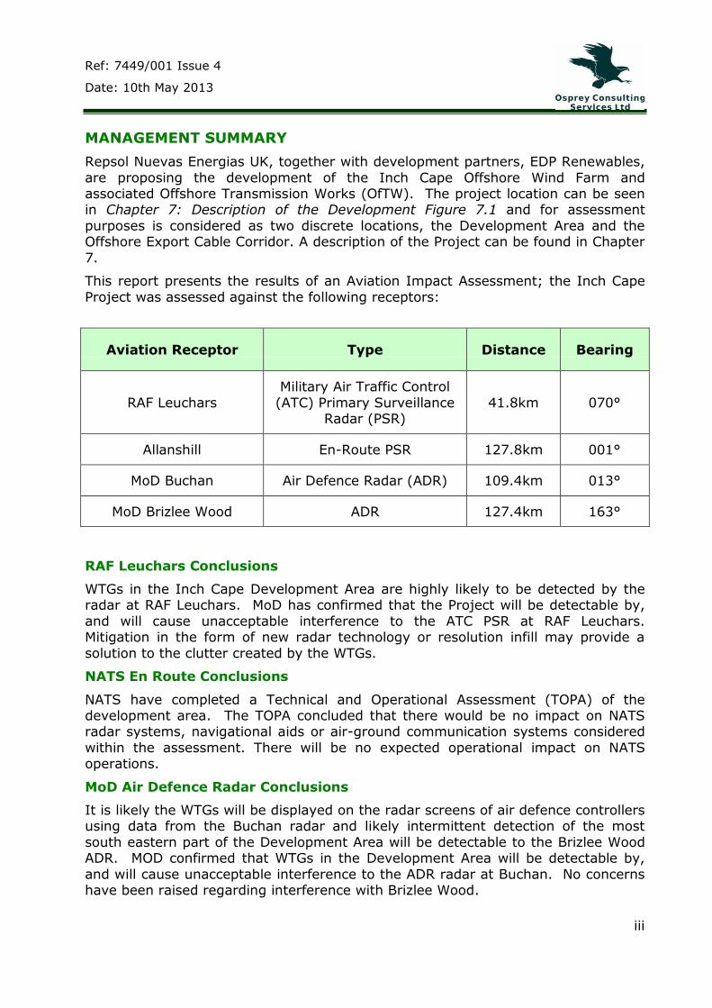
MANAGEMENT SUMMARY
Repsol Nuevas Energias UK, together with development partners, EDP Renewables,
are proposing the development of the Inch Cape Offshore Wind Farm and associated Offshore Transmission Works (OfTW). The project location can be seen in Chapter 7: Description of the Development Figure 7.1 and for assessment
purposes is considered as two discrete locations, the Development Area and the Offshore Export Cable Corridor. A description of the Project can be found in Chapter
7.
This report presents the results of an Aviation Impact Assessment; the Inch Cape
Project was assessed against the following receptors:
Aviation Receptor Type Distance Bearing
RAF Leuchars
Military Air Traffic Control
(ATC) Primary Surveillance Radar (PSR)
41.8km 070°
Allanshill En-Route PSR 127.8km 001°
MoD Buchan Air Defence Radar (ADR) 109.4km 013°
MoD Brizlee Wood ADR 127.4km 163°
RAF Leuchars Conclusions
WTGs in the Inch Cape Development Area are highly likely to be detected by the radar at RAF Leuchars. MoD has confirmed that the Project will be detectable by,
and will cause unacceptable interference to the ATC PSR at RAF Leuchars. Mitigation in the form of new radar technology or resolution infill may provide a
solution to the clutter created by the WTGs.
NATS En Route Conclusions
NATS have completed a Technical and Operational Assessment (TOPA) of the development area. The TOPA concluded that there would be no impact on NATS radar systems, navigational aids or air-ground communication systems considered
within the assessment. There will be no expected operational impact on NATS operations.
MoD Air Defence Radar Conclusions
It is likely the WTGs will be displayed on the radar screens of air defence controllers using data from the Buchan radar and likely intermittent detection of the most
south eastern part of the Development Area will be detectable to the Brizlee Wood ADR. MOD confirmed that WTGs in the Development Area will be detectable by,
and will cause unacceptable interference to the ADR radar at Buchan. No concerns have been raised regarding interference with Brizlee Wood.
Ref: 7449/001 Issue 4
Date: 10th May 2013
iv
Further email correspondence with DIO 19 February 2013 confirmed that the provision on further information on project layout and turbine heights may reduce
potential impact on the ADR at Buchan to an acceptable level and remove the requirement for any technical mitigation.

Ref: 7449/001 Issue 4
Date: 10th May 2013
v
TABLE OF CONTENTS
20A.1 INTRODUCTION ........................................................................... 1
20A.1.1 General ....................................................................................... 1
20A.1.2 Background ................................................................................. 1
20A.1.3 Methodology and Scope ................................................................ 1
20A.1.3.1 Stakeholder Identification ............................................................. 1
20A.1.3.2 Radar Line of Sight Analysis .......................................................... 2
20A.1.3.3 Operational Analysis ..................................................................... 2
20A.1.3.4 Scope ......................................................................................... 3
20A.1.4 Document Structure ..................................................................... 3
20A.2 INCH CAPE DEVELOPMENT AREA .................................................... 5
20A.2.1 Overview .................................................................................... 5
20A.2.2 Map of Location ........................................................................... 5
20A.2.3 Development Area Boundary Coordinates ........................................ 6
20A.2.4 Wind Turbine Generator (WTG) Parameters ..................................... 8
20A.2.5 Estimated Radar Footprint ............................................................. 8
20A.3 RAF LEUCHARS ............................................................................ 9
20A.3.1 Overview .................................................................................... 9
20A.3.2 Runways and Airspace .................................................................. 9
20A.3.3 Radar Line of Sight ....................................................................... 9
20A.3.4 Affected Procedures .................................................................... 10
20A.3.5 Mitigation .................................................................................. 16
20A.3.6 RAF Leuchars Conclusions ........................................................... 17
20A.3.7 Future of RAF Leuchars ............................................................... 17
20A.4 NATS EN-ROUTE (NERL) ............................................................. 19
20A.4.1 Overview .................................................................................. 19
20A.4.2 Radar Line of Sight ..................................................................... 19
20A.4.3 Airspace Structure ...................................................................... 19
20A.4.4 Operational Impact on NERL Operations ........................................ 22
20A.5 MOD AIR DEFENCE RADAR .......................................................... 23
20A.5.1 Overview .................................................................................. 23
20A.5.2 Radar Line of Sight Analysis ........................................................ 23
20A.5.2.1 Buchan ADR .............................................................................. 23
20A.5.2.2 Brizlee Wood ADR ...................................................................... 24

Ref: 7449/001 Issue 4
Date: 10th May 2013
vi
20A.5.3 Operational Impact on Air Defence Operations ............................... 26
20A.5.4 Mitigation .................................................................................. 26
20A.6 OTHER AVIATION ISSUES ........................................................... 27
20A.6.1 Overview .................................................................................. 27
20A.6.2 Search and Rescue Operations (SAR) ........................................... 27
20A.7 CONCLUSIONS AND RECOMMENDATIONS ..................................... 28
20A.7.1 Overview .................................................................................. 28
20A.7.2 RAF Leuchars Impact Conclusions ................................................ 28
20A.7.3 NERL Impact Conclusions ............................................................ 28
20A.7.4 MOD Air Defence Impact Conclusions ........................................... 28
20A.7.5 Recommendations ...................................................................... 29
REFERENCES ............................................................................................... 30
ANNEX 20A.1 –Table Summarising LOS Results ............................................... 32
ANNEX 20A.2 –Line of Sight Terrain Elevation Profiles ....................................... 33

Ref: 7449/001 Issue 4
Date: 10th May 2013
vii
Acronyms and Abbreviations
ADR Air Defence Radar
ANO Air Navigation Order
ATC Air Traffic Control
ATSU Air Traffic Service Unit
CAA Civil Aviation Authority
CAP Civil Aviation Publication
CRC Control and Reporting Centre
DIO Defence Infrastructure Organisation
DS Deconfliction Service
HMR Helicopter Main Route
IMC Instrument Meteorological Conditions
LARS Lower Airspace Radar Service
LAT Lowest Astronomical Tide
MCA Maritime and Coastguard Agency
Mil AIP Military Aeronautical Information Publication
MOD Ministry of Defence
MSA Minimum Safety Altitude
NATS National Air Traffic Service
NERL
PAR
NATS En Route Ltd
Precision Approach Radar
PSR Primary Surveillance Radar
RMS Radar Mitigation Strategy
SAR Search and Rescue
SID Standard Instrument Departure
SSR Secondary Surveillance Radar
TACAN Tactical Aid to Navigation
TD Technical Demonstration
TOPA Technical and Operational Assessment

Ref: 7449/001 Issue 4
Date: 10th May 2013
viii
TRA Temporary Reserved Airspace
UK IAIP UK Integrated Aeronautical Information Package
UKLFS UK Low Flying System
URD User Requirement Document
VFR Visual Flight Rules
WTG Wind Turbine Generators
Ref: 7449/001 Issue 4
Date: 10th May 2013
ix
Glossary
Conditional Route Air traffic service routes of defined airspace which are
useable only under specified conditions.
Deconfliction
Service
Highest level of radar service provided to pilots in Class G
Uncontrolled Airspace: essentially the controller must provide instructions to the pilot to ensure he remains
adequately separated from ‘unknown traffic’ or clutter.
DME A transponder based radio navigation technology; used to determine distance from a land based transponder which can also be co-located within an ILS glide slope antenna.
Final approach
point
The point at which the pilot makes final checks for the
approach to the runway.
Instrument Flight
Rules (IFR)
One of two sets of regulations governing all aspects of
aircraft operation; the other is Visual Flight Rules (VFR). IFR allows a pilot to operate in poor weather when
reference to outside visual cues is not possible.
Instrument
Landing System (ILS)
A ground based instrument approach system that provides
precision guidance to an aircraft approaching a runway.
Instrument Meteorological Conditions
Description of weather conditions that require pilots to fly primarily by reference to aircraft instruments.
Precision
Approach Radar (PAR)
A type of radar guidance system designed to provide
lateral and vertical guidance to an aircraft pilot prior to landing.
Low Flying System
The UK low flying system covers the open airspace of the whole UK below 2,000 ft above ground level. Low Flying
by military aircraft is permitted within established low flying areas which exclude large urban areas.

Ref: 7449/001 Issue 4
Date: 10th May 2013
x
Primary Surveillance
Radar
A radar system that detects objects by means of reflected radio signals.
Secondary
Surveillance Radar
A radar system used in air traffic control that detects and
measures the position of aircraft and provides information on identity and altitude.
Standard Instrument
Departure
A published flight procedure followed by some aircraft immediately after take-off from an airport.
Tactical Aid to Navigation (TACAN)
A navigation system used by military aircraft. It provides the user with bearing and distance information to a ground station. TACAN beacons are usually located within the
airfield boundary.
Visual Flight Rules
A set of regulations under which a pilot operates an aircraft in weather conditions generally clear enough to operate the aircraft with visual reference to the ground and by
visually avoiding obstructions and other aircraft.

Ref: 7449/001 Issue 4
Date: 10th May 2013
1
20A.1 INTRODUCTION
20A.1.1 General
Inch Cape Offshore Limited (ICOL) is proposing a development of the Inch Cape Offshore Wind Farm and associated Offshore Transmission Works (OfTW). The
Project location can be seen in figure 7.1 and for assessment purposes is considered as two discrete locations, the Development Area and the Offshore
Export Cable Corridor. A description of the Project can be found in Chapter 7: Description of Development.
This technical report describes the existing environment with regard to the civil and
military aviation within and around the Development Area and Offshore Export Cable Corridor, through the evaluation of existing data source and desk studies,
and consultation with key stakeholders. Subsequently the report presents an assessment of the predicted impacts of the construction, operation and
decommissioning phases of the Wind Farm and associated OfTW on aviation interests. Details of mitigation are also presented.
The assessment has been carried out in accordance with CAA guidance CAP 764
[Reference 1]. The assessment was conducted by Osprey Consulting Services (Osprey) on behalf of ICOL.
20A.1.2 Background
There is the potential for a range of effects resulting from wind farms on aviation interests but effects generally fall into two dominant scenarios that lead to
objection from aviation stakeholders:
1. Physical: Wind Turbine Generators (WTGs) and related infrastructure can
present a physical obstruction at or close to an aerodrome;
2. Radar/Air Traffic Services: WTG clutter appearing on a radar display can
affect the safe provision of air traffic services as it can mask unidentified aircraft from the air traffic controller and/or prevent him from accurately identifying aircraft under his control. In some cases, radar reflections from
the WTG can affect the performance of the radar system itself.
Potential impacts to aviation from the Wind Farm and OfTW infrastructure mainly
result from the presence of WTGs. This is because they are the tallest and most prevalent infrastructure on the site and therefore present the greatest potential for physical obstruction. Other infrastructure such as met masts or Offshore
Substation Platforms (OSPs) will always be a lower maximum height than the WTGs; radar clutter is caused by the rotational motion of WTG blades and not static
infrastructure. The entire OfTW infrastructure in the Offshore Export Cable Corridor is below sea level and therefore has no potential to impact on aviation interest. As such the OfTW infrastructure is not considered any further in this assessment.
20A.1.3 Methodology and Scope
20A.1.3.1 Stakeholder Identification
Osprey uses a number of resources including some that have been developed in-house to identify aviation stakeholders at the beginning of an assessment. Sources
may include Aeronautical Charts, the UK Integrated Aeronautical Information

Ref: 7449/001 Issue 4
Date: 10th May 2013
2
Package (UK IAIP), Military Aeronautical Publication (Mil AIP), Pooleys guide for farm strips and small airfields and internal data bases. Identification begins with
the consultation zones for the various airfield types as described in CAP 764 [Reference 1]. However an additional margin is always incorporated to recognise that historical objections have come from outside these areas.
20A.1.3.2 Radar Line of Sight Analysis
Osprey used the ATDI ICS Basic Version 10 tool to model the terrain elevation
profile between the given radar and coordinates of the Development Area. Otherwise known as a point-to-point line of sight analysis the result is a graphical representation of the intervening terrain and the direct signal line of sight (taking
into account earth curvature and radar signal properties).
This analysis is a theoretical desk based study and in reality there are unpredictable
levels of signal diffraction and attenuation within a given radar environment that can influence the probability of a WTG being detected. It is therefore recognised that there are limitations in the analysis and the analysis is designed to give an
indication of the likelihood of WTGs in the Development Area being detected such that the operational significance of the Wind Farm relative to nearby aviation assets
can be assessed.
The qualitative definitions used in the assessment are defined in Table 20A.1 below.
Table 20A.1 Qualitative Definitions of Line of Sight Results
Result Definition
Yes the WTG is highly likely to be detected by the radar: direct line of
sight exists between the radar and the WTG
Likely the WTG is likely to be detected by the radar at least intermittently
Unlikely the WTG is unlikely to be detected by the radar but cannot rule out occasional detection
No the WTG is unlikely to be detected by the radar as significant intervening terrain exists
20A.1.3.3 Operational Analysis
For licensed and military aerodromes Osprey makes use of published procedures in the UK IAIP and Mil AIP as appropriate as well as extensive experience of the applicable regulatory requirements for the safe provision of air traffic control
services in carrying out the assessment. For unlicensed aerodromes Osprey use knowledge of the regulations and operational experience to apply the expected
safeguarding standards to unlicensed airfields. Information regarding obstacles and procedures published by unlicensed airfields i.e. through their websites or safeguarding maps lodged with the Local Planning Authorities is also taken into

Ref: 7449/001 Issue 4
Date: 10th May 2013
3
consideration. Every assessment carried out by Osprey is overseen by at least one Air Traffic Control expert who will have significant levels of active service.
20A.1.3.4 Scope
This appendix considers the impact of the Inch Cape WTGs during operation. Safety issues relating to the visibility (e.g. lighting) of the WTGs within the Development
Area are considered in Appendix 20B: Aviation and Lighting Requirements. In particular it is recognised that tall slender constructions such as WTGs, despite their
size, can be difficult to see from the air in certain weather conditions. Guidance has been issued by RenewableUK [Reference 2], which recommends that to facilitate safe visual flight, day or night, in the vicinity of anemometer masts and/or WTGs:
Information regarding construction should be passed to the Defence Geographic Centre and the General Aviation Awareness Council at least 6
weeks in advance of the erection or removal of an anemometer mast or first WTG and to follow up on the day with a confirmation that the activity has taken place;
o Data should include location, height (of all structures over 150 feet (ft)), date of erection, date of removal and lighting type (none, infra-
red or lighting brightness);
o Local aerodromes identified during consultation should be notified, particularly any police helicopter or air ambulance unit; and
o RenewableUK should be copied on the submission of all such information as an independent record and that they might share the
information with other relevant official agencies.
Appropriate information about the site construction and any associated lighting (where applicable), for example the height and temporary location of
construction cranes, should be provided to the UK Aeronautical Information Service (NATS AIS) for promulgation in applicable aviation publications
including the UK Integrated Aeronautical Information Publication (UK IAIP) [Reference 7].
The relevant existing legislation regarding obstacles to air navigation includes the following:
Obstacles close to licensed aerodromes: Section 47, Civil Aviation Act 1982;
Obstacles close to government aerodromes: Town and Country Act,
(Government permitted development) Order 2000;
Lighting of en-route obstacles: Article 220, Air Navigation: The Order and the Regulations 2010 (CAP 393) [Reference 3]. Further detail is provided in
Appendix 20B.
20A.1.4 Document Structure
The document utilises the following structure:
Section 1 gives an introduction to the report;
Section 2 introduces the Wind Farm;

Ref: 7449/001 Issue 4
Date: 10th May 2013
4
Section 3 examines the potential impact of the development on operations at RAF Leuchars;
Section 4 outlines the potential impact on NERL radars;
Section 5 identifies any potential impact on MOD Air Defence operations; and
Section 6 presents the conclusions and recommendations.
All References used in this document are listed at the end and there are two annexes:
Annex 20A.1 provides a summary of anticipated WTG visibility to aviation PSRs; and
Annex 20A.2 provides a full set of Radar Line of Sight Terrain Elevation
Profiles used for the analysis in this report.

Ref: 7449/001 Issue 4
Date: 10th May 2013
5
20A.2 INCH CAPE DEVELOPMENT AREA
20A.2.1 Overview
The Development Area is situated off-shore to the east of the Angus coastline, Scotland. A maximum of 213 WTGs will be installed in the Development Area.
20A.2.2 Map of Location
Figure 20A.1 shows the map of the Development Area location.
Figure 20A.1 Development Area
Reproduced from Ordnance Survey digital map data © Crown copyright 2012. All rights reserved.
Figure 20A.2 below shows the Development Area and the locations of the radars assessed within the document.
Ref: 7449/001 Issue 4
Date: 10th May 2013
6
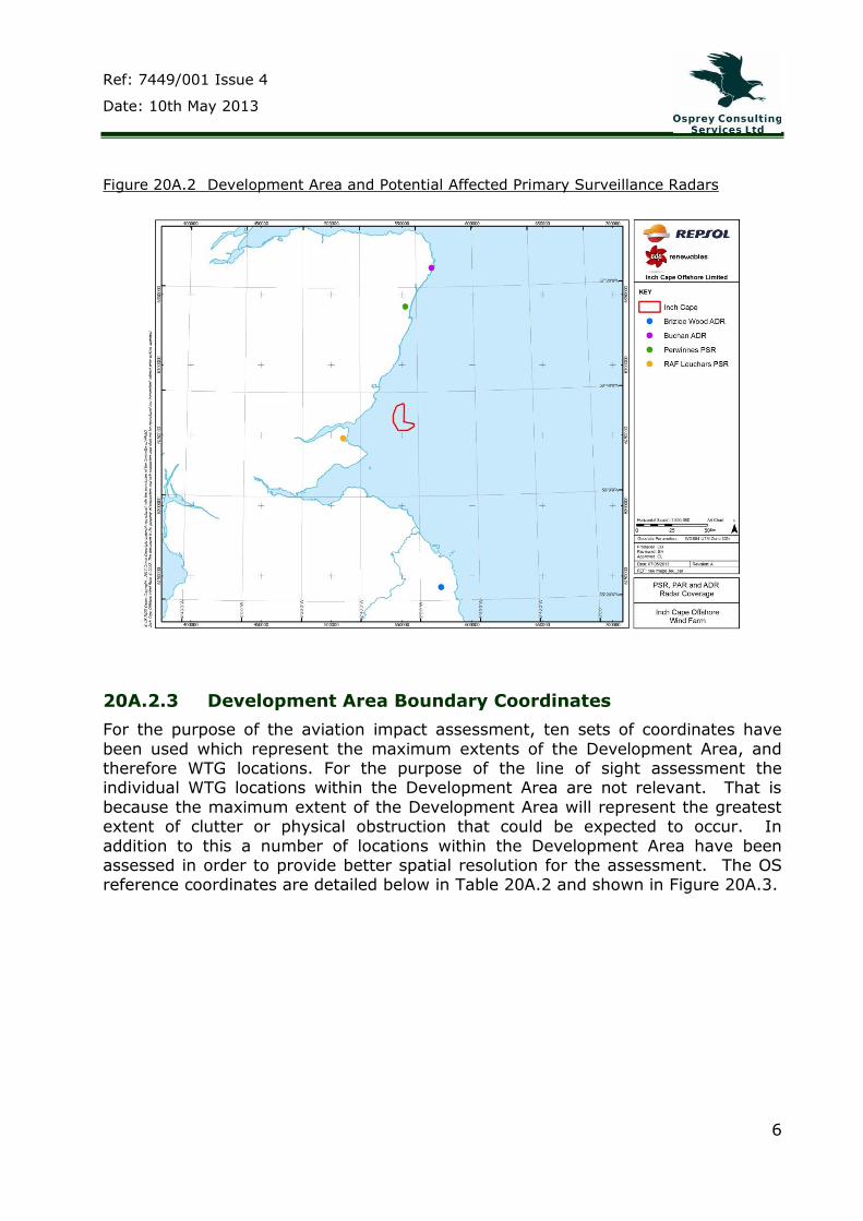
Figure 20A.2 Development Area and Potential Affected Primary Surveillance Radars
20A.2.3 Development Area Boundary Coordinates
For the purpose of the aviation impact assessment, ten sets of coordinates have
been used which represent the maximum extents of the Development Area, and therefore WTG locations. For the purpose of the line of sight assessment the individual WTG locations within the Development Area are not relevant. That is
because the maximum extent of the Development Area will represent the greatest extent of clutter or physical obstruction that could be expected to occur. In
addition to this a number of locations within the Development Area have been assessed in order to provide better spatial resolution for the assessment. The OS reference coordinates are detailed below in Table 20A.2 and shown in Figure 20A.3.

Ref: 7449/001 Issue 4
Date: 10th May 2013
7
Table 20A.2 ICOL Line of Sight Assessment Location Coordinates
Development
Area Coordinate
Eastings Northings
ICOL A 397208 728451
ICOL B 392328 725577
ICOL C 385902 725670
ICOL D 382411 731833
ICOL E 382484 736818
ICOL F 384813 742889
ICOL G 389723 744763
ICOL H 390371 743575
ICOL I 389830 731691
ICOL J 397183 730129
ICOL K 386775 738980
ICOL L 385940 733755
ICOL M 387142 729476
ICOL N 392637 728294

Ref: 7449/001 Issue 4
Date: 10th May 2013
8
Figure 20A.3 Development Area Line of Sight Assessment Location Coordinates
20A.2.4 Wind Turbine Generator (WTG) Parameters
The proposed WTGs will have a maximum blade tip height of 215 metres (m) above LAT; although the actual blade tip height may differ depending on WTGs utilised. WTGs may be installed anywhere within the Development Area however discrete
areas may not be utilised due to technical or environmental constraints. Blade tip heights will be largely consistent, although there may be some variations to allow
for standardisation of substructures in varying water depths.
20A.2.5 Estimated Radar Footprint
The proposed WTG layout physically occupies the Development Area which measures approximately 19.05km (10.29 nautical miles (NM)) north south and 14.81km (8.00NM) east west. Allowing for the nominal 100m wide1 extent of
clutter either side of a single WTG, the potential size of the footprint as represented on a typical Primary Surveillance Radar (PSR) display system is approximately
19.25km by 15.01km (10.39 by 8.10NM).
1 This is an estimate; the size of the clutter will depend on range and the specific operating
parameters of the radar (e.g. range-azimuth cell size) i.e. the clutter could appear larger at
a greater range from the radar.
Ref: 7449/001 Issue 4
Date: 10th May 2013
9
20A.3 RAF LEUCHARS
20A.3.1 Overview
RAF Leuchars is currently the most northerly air defence station in the UK. It is located in Leuchars, Fife, on the east coast of Scotland. It is currently home to No’s
1 (Fighter) and 6 Squadrons operating Typhoon aircraft, which provide Quick Reaction Alert (QRA) combatting any threat to the UK from the air. The East of
Scotland University Air Squadron and No 12 Air Experience Flight provide training and air experience utilising the Grob Tutor aircraft.
20A.3.2 Runways and Airspace
RAF Leuchars has a main runway which is 2589 m in length and is orientated 08/26 (denotes the first two figures of the approximate bearing of the take-off/landing
direction, i.e. 080°/260°). Leuchars operates a secondary runway: Runway 04/22 which is used by Leuchars based light aircraft and helicopters.
20A.3.3 Radar Line of Sight
The Development Area is approximately 41km (22.6 NM) from the radar at RAF
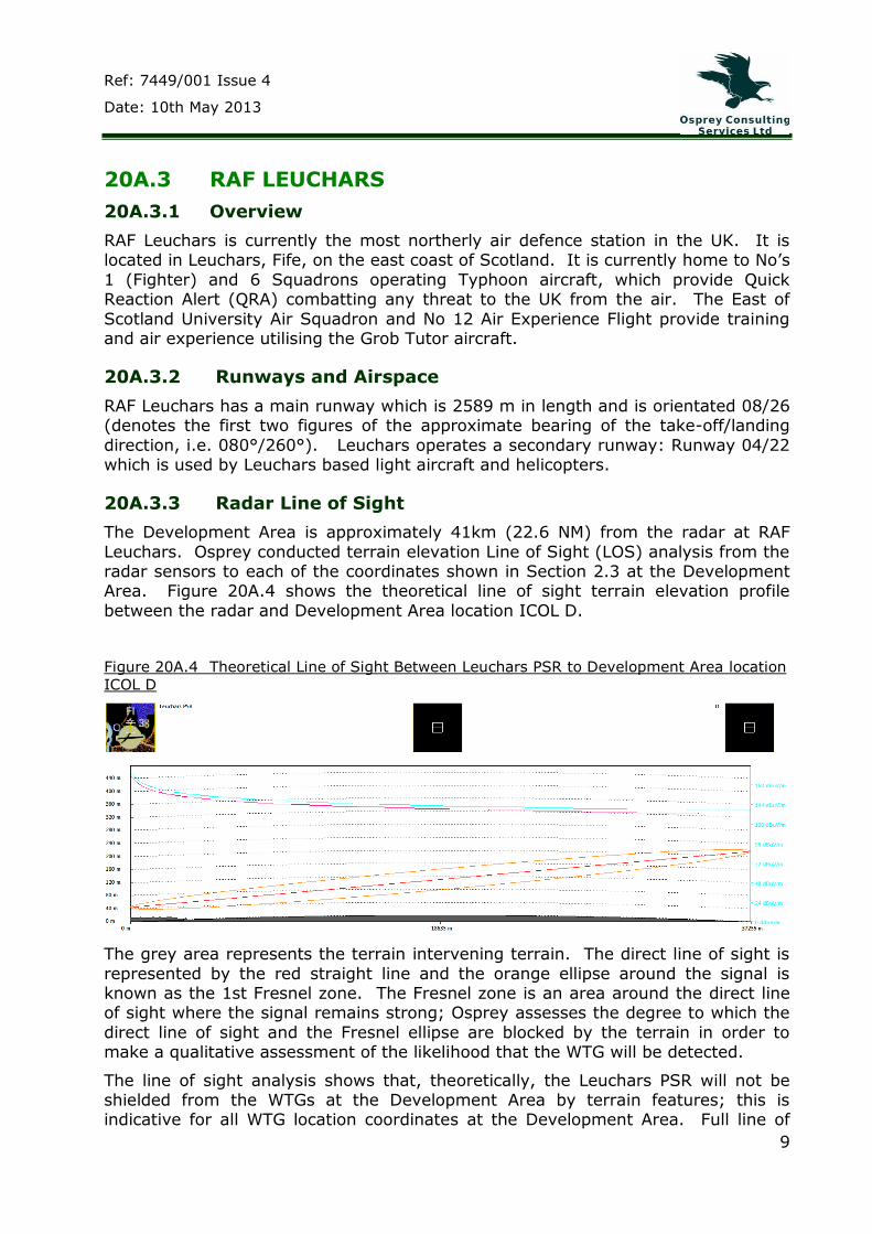
Leuchars. Osprey conducted terrain elevation Line of Sight (LOS) analysis from the radar sensors to each of the coordinates shown in Section 2.3 at the Development Area. Figure 20A.4 shows the theoretical line of sight terrain elevation profile
between the radar and Development Area location ICOL D.
Figure 20A.4 Theoretical Line of Sight Between Leuchars PSR to Development Area location
ICOL D
The grey area represents the terrain intervening terrain. The direct line of sight is
represented by the red straight line and the orange ellipse around the signal is known as the 1st Fresnel zone. The Fresnel zone is an area around the direct line of sight where the signal remains strong; Osprey assesses the degree to which the
direct line of sight and the Fresnel ellipse are blocked by the terrain in order to make a qualitative assessment of the likelihood that the WTG will be detected.
The line of sight analysis shows that, theoretically, the Leuchars PSR will not be shielded from the WTGs at the Development Area by terrain features; this is indicative for all WTG location coordinates at the Development Area. Full line of

Ref: 7449/001 Issue 4
Date: 10th May 2013
10
sight profiles are contained in Annex 20A.2 to this document; these profiles indicate that all of the area planned for the WTGs will be visible to the Leuchars radar.
20A.3.4 Affected Procedures
The controllers at Leuchars provide radar services for aircraft on departure and recovery to the airfield, as well as a Lower Airspace Radar Service (LARS) to
participating aircraft.
Leuchars publishes a number of precision approach, standard arrival and departure
procedures within the Military Aeronautical Information Publication (Mil AIP) [Reference 4] and Osprey has studied each of these to identify those that might be
affected by the WTG clutter. Table 20A.3 describes the nearest procedures that are within the Development Area vicinity.
Table 20A.3 Nearest Procedures to the Development Area
Arrival
Procedure Description
Range from wind farm at closest
point
1. High TACAN to
PAR Runway 08.
-----------------
2. TACAN or RDR to ILS/DME2 Runway 26.
Aircraft use information derived from the TACAN to position at a pre-defined hold position (3.1 NM bearing 243°
from the Development Area). This point is known as the Initial Approach
Fix (IAF). Arrivals to the hold point2 fly a west east racetrack before being given approval to leave the hold by
the air traffic controller to arrive at the final approach point.
Aircraft positioned in the hold will overfly
the southern edge of the Development
Area.
3. High TACAN to Runway 26
Aircraft use information derived from the TACAN to position at a pre-defined
hold position. The hold position for this procedure is situated approximately 10.7 NM to the east of
the Development Area. Arrivals to the hold point fly a west east
racetrack before being given approval to leave the hold by the air traffic controller to arrive at the final
approach point.
On leaving the hold
and inbound to Leuchars, aircraft will pass approximately
within 1 NM of the southern edge of the
development.
2 A holding pattern is usually a racetrack based on a holding fix. It is used to delay aircraft
that have arrived at their destination but cannot land due to traffic congestion, poor
weather or runway unavailability

Ref: 7449/001 Issue 4
Date: 10th May 2013
11
Procedures are said to be affected by WTG clutter if they pass within 5 NM of the clutter created by a wind farm area. 5 NM is the standard separation distance that
Air Traffic Controllers must apply between aircraft under their control and unknown aircraft (or clutter that looks like a real aircraft or could be assumed to be masking returns from a real aircraft).
Clutter likely to be generated by the WTGs within the Development Area could obscure aircraft under control. The clutter could be hiding a genuine, conflicting
aircraft return.
The radar assisted arrival procedures to RAF Leuchars which utilise the TACAN hold procedures from the east for runway 08/26 are affected by the location of the
expected Wind Farm clutter. The TACAN procedures are likely to be frequently used to maintain currency with aircrews.
In the vicinity of the Development Area, aircraft will be transiting through Class G Uncontrolled Airspace (anyone can fly here without talking to ATC) and may request a Deconfliction Service (DS) from the controllers at Leuchars.
For an aircraft requesting a DS, the air traffic controller will be unable to provide the 5 NM separation required (between wind farm clutter and an aircraft) for the
safe provision of the service.
The illustrations overleaf in Figures 20A.5, 20A.6 and 20A.7 show the approximate position of the Development Area with respect to the above procedures.

Ref: 7449/001 Issue 4
Date: 10th May 2013
12
Figure 20A.5 Indicative illustration of position of the Development Area to RAF
Leuchars Hi TACAN to PAR procedure Runway 08 (not to scale)
© UK MoD Crown Copyright, 2012 Crown Copyright material reproduced with the
permission of the Controller of HMSO

Ref: 7449/001 Issue 4
Date: 10th May 2013
13
Figure 20A.6 Indicative illustration of position of the Development Area to RAF
Leuchars TACAN or Radar to ILS/DME procedure Runway 26 (not to scale)
© UK MoD Crown Copyright, 2012 Crown Copyright material reproduced with the permission of the Controller of HMSO

Ref: 7449/001 Issue 4
Date: 10th May 2013
14
Figure 20A.7 Indicative illustration of position of the Development Area to RAF
Leuchars TACAN procedure Runway 26 (not to scale)
© UK MoD Crown Copyright , 2012 Crown Copyright material reproduced with the permission of the Controller of HMSO
The holding procedures for Leuchars utilising the TACAN are affected by the location of the expected WTG clutter. The impact on the provision of radar services to aircraft flying the procedures is predicted to be significant and likely to require
mitigation. There may be scope to move the position of the TACAN hold, this will require discussion with MOD.
Aircraft recovering to the airfield, under an air traffic service, from the vicinity of the Development Area (not utilising the TACAN hold procedure) are also likely to be affected by the expected clutter, as the airspace available to the controllers to
manoeuver aircraft into the recovery stream under a DS is reduced due to the fact that controllers are mandated to maintain standard separation of 5 NM on any
unknown contact.
Departing aircraft flying under Instrument Flight Rules (IFR) from the airfield will normally follow a published departure procedure which will keep aircraft clear of
terrain. The aircraft will follow a Standard Instrument Departure (SID) profile immediately after take-off. SIDs are a published flight procedure followed by some
aircraft immediately after take-off from an airport and strike a balance between obstacle clearance, noise abatement and airspace management considerations.

Ref: 7449/001 Issue 4
Date: 10th May 2013
15
Aircraft departing under Visual Flight Rules (VFR) will normally depart the airfield via the most expeditious route, which may include flying the SID.
Leuchars publish four SIDs for each runway. The SID1 for runway 08/26 takes the aircraft towards the Development Area.
Figure 20A.8 illustrates the SIDs for runway 08 and the position of the
Development Area.
Figure 20A.8 Indicative illustration of position of the Development Area to RAF
Leuchars Runway 08 SIDs (not to scale)
© UK MoD Crown Copyright, 2012 Crown Copyright material reproduced with the permission of the Controller of HMSO
The SID1 for Runway 26 initially heads west before turning east towards the Development Area. Timely heading selection by the RAF Leuchars Air Traffic
Controllers for aircraft requesting a DS on a SID1 for both Runways 08/26 will facilitate provision of separation from the Inch Cape WTGs. Osprey considers that
there is sufficient airspace available to controllers of departing aircraft to maintain 5 NM or more from the Development Area.
Leuchars is also provider of the Lower Airspace Radar Service (LARS). LARS is a national system within which participating civil and military Air Traffic Service Units (ATSUs) provide a radar service to aircraft, subject to controlling capacity, within
approximately 30-40 NM of each unit. LARS is established to enhance the safety
Ref: 7449/001 Issue 4
Date: 10th May 2013
16
and the efficiency of air traffic services provided to aircraft flying from or close to aerodromes not protected by controlled airspace. It encourages aircraft flying
through the area to receive an air traffic service allowing air traffic controllers to separate aircraft based on known intentions and therefore reduce the need for avoiding action. Controllers will need to provide 5 NM separation between an
aircraft in receipt of a DS and any radar clutter which has the potential to obscure unknown targets. Use of LARS in the proximity of the Development Area would be
limited; light civilian aircraft tend to stay overland as they invariably do not carry the relevant safety equipment to operate at a distance from the coastline. However, for aircraft requesting LARS in the vicinity of the Development Area the
type of service provided would be restricted.
20A.3.5 Mitigation
An infill radar solution involves the removal of PSR data where radar clutter is anticipated in the vicinity of a wind farm, and replacing it with an alternate radar
source which is not affected by the WTG clutter. The MOD has published a draft user requirement document (URD) for ‘The sustainment of military air traffic control (ATC) primary surveillance capability with wind turbines in radar line of sight’
[Reference 5]. This document determines the standards stipulated by the MOD for acceptable integration of an infill solution. The MOD has expressed concern that
the integrity of the boundaries between these data sources needed protection to prevent boundary corruption which can lead to loss of radar plots, duplication of plots and misalignment of the synthetic video radar responses.
A number of emerging technologies may potentially offer acceptable technical mitigation for ATC impacts pending demonstration and acceptance by the MOD.
The MOD and the Department of Energy and Climate Change (DECC) are carrying out a technology demonstration (TD) programme in the summer of 2013 which will allow technologies to demonstrate performance and compliance against the URD for
impacts on ATC radar. It is expected that the TD will inform the agreement of acceptable mitigation with the MOD.
The emerging technologies fall into different categories and include, but are not limited to:
Resolution Infill
Resolution infill consists of a sensor that is located within or near to a Wind Farm and provides surveillance of a given volume surrounding a Wind Farm. The sensor
does not scan in the same way as a traditional PSR and is able to distinguish between WTGs and aircraft. The clutter free coverage volume can then be used to enhance the display by suppressing the radar returns. The technology is still in
development. It is understood that resolution infill systems will include bespoke radar system integration solutions; work is on-going how to integrate the data into
the controllers’ display. Examples of resolution infill solutions include:
Aveillant HR Infill Holographic RadarTM: a small scale sensor developed by Aveillant which is primarily designed to be located with the affected PSR system
or can be installed within or in proximity to the wind farm itself; and

Ref: 7449/001 Issue 4
Date: 10th May 2013
17
C Speed LightWave Radar: designed to be co-located with the affected PSR system and exploits the basic principles of radar operation in order to distinguish
between returns from aircraft and returns from WTGs.
Display Enhancements
The Thruput Midas family of mitigation includes Midas III, a system designed for
use with raw video radar data; and Midas IV, designed for implementation in a digital processed display system. The systems are different in terms of their
approach to removing WTG radar returns, although due to the commercial confidentiality of the development programme, technical detail is not available to be elaborated further. It is anticipated that both systems will however undergo
extensive trial and integration activities in the next 12 months, at different airports across the UK.
Radar Replacements or Enhancements
BAE Systems Watchman Update: The equipment manufacturer of the Watchman radar which is in use across a large number of RAF bases is developing wind
farm mitigation for their radar system.
Terma Scanter 4002: this is a maritime radar which could be used as an air
surveillance radar with the benefit of providing inter-turbine visibility and the ability to track aircraft inside and around wind farms. It may be deployed as a radar replacement, or as a resolution infill as described above. A Scanter 4002
system is currently installed at Copenhagen Airport, where the local Air Traffic Controllers are able to review performance of detecting aircraft in the vicinity of
a number of WTGs. The radar is an X-Band system, which operates in a higher frequency than traditional S-Band ATC radar, which leads to the following capabilities: improved pulse compression; narrow beamwidth; less
desensitisation; and increased accuracy. The radar has a range of 40 NM, and could therefore be a suitable candidate for RAF Leuchars.
Cassidian ASR-NG: this is a combined Primary/Secondary radar system which includes technology that allows for safe guidance of aircraft in the vicinity of WTGs. It is unknown how the technology inherent in this system successfully
mitigates the effect of WTGs on radar. Further analysis is required to ascertain specific detail as to whether this system can be utilised.
20A.3.6 RAF Leuchars Conclusions
All of the WTGs at the Development Area will theoretically be detected by the PSR
at Leuchars leading to a potential operational impact. The patch of clutter likely to be produced on the radar display is within the path taken by aircraft descending into the airfield. Correspondence from MOD dated letter 12 February 2013 confirms
that the proposed Project will be detectable by, and will cause unacceptable interference to the ATC PSR Radar at RAF Leuchars.
20A.3.7 Future of RAF Leuchars
The previous Secretary of State for Defence, Liam Fox, announced in parliament
during 2011 that RAF Leuchars would become an army base and the Typhoon aircraft at the unit, which operate in the air defence role, would move to RAF Lossiemouth, Morayshire during 2013.

Ref: 7449/001 Issue 4
Date: 10th May 2013
18
Until the future of the airfield facilities has been decided upon there will be a period of uncertainty whilst the facilities are prepared for transfer to the British Army.
It is Osprey’s opinion that the Defence Infrastructure Organisation (DIO) will continue to safeguard the airfield until a final decision on the future use of the airfield and its facilities has been decided upon.
The present flight procedures for the airfield are based on utilisation by fast jet aircraft. If the future of the airfield lies with Army aviation and subsequently the
airfield is utilised predominantly by helicopters, it is Osprey’s opinion that the present structure of flight procedures for aircraft inbound to the airfield are likely to change.
Ref: 7449/001 Issue 4
Date: 10th May 2013
19
20A.4 NATS EN-ROUTE (NERL)
20A.4.1 Overview
NATS En-Route Plc (“NERL”) provides radar and air traffic services to ‘en-route’ traffic throughout the UK3. Military and other civilian aerodromes often receive a remote feed of secondary surveillance radar data from their nearest NERL radar
and therefore any effect the proposed Wind Farm and OfTW in the Development Area might have on NERL radars must be considered both in terms of effect on the
en-route services and in the context of its remote users.
20A.4.2 Radar Line of Sight
NATS En-route (NERL) was initially consulted in early 2010 and a Technical and Operational Assessment (TOPA) [Reference 6] was completed by NATS during April 2010 and revised in February 2013 (Appendix 20C).
The NATS TOPA assessed any effect on NATS navigational aids, air-ground voice communication systems and the following radar systems:
Claxby Radar located in Lincolnshire;
Great Dun Fell Radar located in Cumbria;
Lowther Hill Radar located in Dumfries and Galloway;
Perwinnes Radar located in Aberdeenshire; and
Tiree Radar located in Argyll.
The TOPA concluded that there would be no impact on NATS radar systems, navigational aids or air-ground communication systems considered within the assessment.
There is a NATS radar located near Fraserburgh, Aberdeenshire and although not completed within the TOPA, a radar line of sight assessment from the Allanshill
PSR, to the WTG placement coordinates within the Development Area was completed by Osprey for completeness; the results indicated theoretically that
WTGs, will not be detected by the Allanshill PSR.
20A.4.3 Airspace Structure
The airspace directly overhead the Development Area is predominately Class G
uncontrolled airspace from surface level to 19,500 ft (FL 195). However, a portion of airway P18 skirts the eastern edge of the Development Area.
Airway P18 is a conditional route, within controlled airspace, which extends from FL 135 to FL 245. Conditional routes are routes that are only available under published times in the UK Aeronautical Information Package (UK IAIP) [Reference
7]. Airway P18 has many restrictions and is open Tuesday-Friday 0530-0900, and from 1500 Friday or the day preceding a Public Holiday (PH) to 1000 Monday or the
3 Note that NATS also provide air traffic services at some airports within the UK under the
NATS (Services) Plc.
Ref: 7449/001 Issue 4
Date: 10th May 2013
20
day following a PH Winter (summer 1 hour earlier); it is additionally available
overnight May-September, Monday-Thursday 1900-0900. However in all instances the airway is not available when MOD requires access to the airspace.
Extending upwards from FL195 to FL245 is Class C controlled airspace which forms Temporary Reserved Area (TRA) 007A. To avoid operational restrictions, TRAs allow for military aircraft to work autonomously under Visual Flight Rules (VFR) or
be in receipt of an ATS from approved ATS units. Aircraft operating in TRA 007 will be under the control of Scottish Military air traffic controllers who utilise the same
radars which are available to their civil counterparts. TRA 007A is activated Monday through to Friday between the hours of 0730-1700 during the summer and 0830-1700 during the months of winter.
Additionally, there are two upper Air Traffic Service (ATS) routes; UP18 and UP59 which extend from FL245-FL460 which overfly the development. Upper ATS routes
have no declared width but for the purpose of ATS provision are deemed to be 5 NM either side of a straight line joining each two consecutive points on the route. The centre of airway UP59 is approximately 2.8 NM south west of the Development
Area.
The airspace structure above the Development Area is shown in Figure 20A.9; while
Figure 20A.10 displays the Upper Air Routes.

Ref: 7449/001 Issue 4
Date: 10th May 2013
21
Figure 20A.9 Airspace Structure in the Vicinity of the Development Area

Ref: 7449/001 Issue 4
Date: 10th May 2013
22
Figure 20A.10 Airway Features in the Vicinity of the Development Area (not to scale).
CAA, 2011a.
Reproduced with the permission of NATS
20A.4.4 Operational Impact on NERL Operations
The Development Area is adjacent to a conditional route P18 which is only available during limited hours of operation. Furthermore, the Development Area is underneath TRA007A, airspace which is used by the military for training. Aircraft in
TRA007A would be receiving a radar service from military controllers at the Prestwick Centre. The Development Area is also between two Upper Air Routes
which extend from FL245-FL460.
The TOPA assessed any potential for effects on NATS navigational aids, air-ground voice communication systems and any NATS radar systems within operational
range. The TOPA concluded that no impact on NATS en-route radar is anticipated.

Ref: 7449/001 Issue 4
Date: 10th May 2013
23
20A.5 MOD AIR DEFENCE RADAR
20A.5.1 Overview
The Air Surveillance and Control System (ASACS) are responsible for the homeland defence of the UK. A series of fixed air defence radar feed into the Control and Reporting Centre (CRC) at RAF Boulmer and RAF Scampton, where the UK
Recognised Air Picture (RAP) is produced. There are two air defence radars in operational range of the ICOL development:
Buchan situated near Peterhead, Aberdeenshire; and
Brizlee Wood situated on Alnwick Moor, Northumberland.
Buchan ADR is located approximately 109.4 km north north-east of the
Development Area. Brizlee Wood ADR is located 127.4 km south south-east of the southern edge of the Development Area.
20A.5.2 Radar Line of Sight Analysis
20A.5.2.1 Buchan ADR
Figure 20A.13 shows the line of sight profile between the MOD Buchan ADR and the closest Development Area coordinate, that of coordinate ICOL G.
Figure 20A.11 Theoretical Line of Sight between Buchan ADR to Development Area
location ICOL G
The line of sight diagram shows that, theoretically, the location is highly likely to be detected by the Buchan ADR. Full line of sight profiles are contained in Annex
20A.2 to this document; these profiles indicate that the results vary by Development Area boundary location as indicated in Table 20A.4.

Ref: 7449/001 Issue 4
Date: 10th May 2013
24
Table 20A.4 Theoretical Indicative Visibility of Development Area Coordinates to the
Buchan ADR
Site
Coordinate
Visibility to Buchan
ADR
ICOL A Likely
ICOL B Likely
ICOL C Likely
ICOL D Likely
ICOL E Likely
ICOL F Yes
ICOL G Yes
ICOL H Yes
ICOL I Likely
ICOL J Likely
ICOL K Likely
ICOL L Likely
ICOL M Likely
ICOL N Likely
Development Area coordinates A to E and I through to N are likely to be detected
by the radar, the analysis shows that the location is likely to be detected at least intermittently: a small part of the 1st Fresnel zone is blocked.
20A.5.2.2 Brizlee Wood ADR
Figure 20A.14 shows the line of sight profile between the MOD Brizlee Wood ADR and the closest Development Area coordinate, that of coordinate B.

Ref: 7449/001 Issue 4
Date: 10th May 2013
25
Figure 20A.12 Theoretical Line of Sight between Brizlee Wood ADR to
Development Area location ICOL B
The line of sight diagram shows that, theoretically, the location is likely to be
detected by the Brizlee Wood ADR. Full line of sight profiles are contained in Annex 20A.2 to this document; these profiles indicate that the results vary by Development Area boundary location as indicated in Table 20A.5.
Table 20A.5 Theoretical Indicative Visibility of Development Coordinates to the Brizlee
Wood ADR
Site Coordinate
Visibility to Brizlee Wood ADR
ICOL A Likely
ICOL B Likely
ICOL C Unlikely
ICOL D No
ICOL E No
ICOL F No
ICOL G No
ICOL H No
ICOL I Unlikely
ICOL J Likely
ICOL K No
ICOL L No
ICOL M Unlikely
ICOL N Unlikely

Ref: 7449/001 Issue 4
Date: 10th May 2013
26
Development Area coordinates A, B and J (the south eastern area of the
Development Area) are likely to be detected by the Radar, the analysis shows that the location is likely to be detected at least intermittently: a small part of the 1st
Fresnel zone is blocked.
20A.5.3 Operational Impact on Air Defence Operations
It is likely the WTGs will be displayed on the radar screens of air defence controllers
using data from the Buchan ADR radar and likely intermittent detection of the most south eastern part of the Development Area (coordinates A, B and J) will be seen
by the Brizlee Wood ADR. This has the potential to obscure genuine targets and could have safety implications for aircraft under control. MOD letter 12 February
2013 confirmed that WTGs in the Development Area will be detectable by, and will cause unacceptable interference to the ADR radar at Buchan. No concerns have been raised regarding interference with Brizlee Wood [Reference 8].
Further email correspondence with DIO 19 February 2013 confirmed that the provision on further information on Project layout and WTG heights may reduce
potential impact on the ADR at Buchan to an acceptable level and remove the requirement for any technical mitigation.
20A.5.4 Mitigation
The MOD has agreed to the installation of the Lockheed Martin TPS-77 radar at three air defence east coast radar stations in mitigation against the effect of wind
farm clutter on radar displays.
The Lockheed Martin FPS-117 (MOD Type 92) radar is in use at Buchan and is operated remotely. The Lockheed Martin FPS-117 radar is similar in operation to
the Lockheed Martin TPS-77 Air Defence Radar. It is Osprey’s opinion that consultation with MOD should be undertaken to provide further information on
Project layout and WTG heights which may reduce potential impact on the ADR at Buchan to an acceptable level and remove the requirement for any technical
mitigation. If this solution is not viable then it should be considered if a software upgrade to the Buchan ADR could act as mitigation against clutter created by the Wind Farm.
Ref: 7449/001 Issue 4
Date: 10th May 2013
27
20A.6 OTHER AVIATION ISSUES
20A.6.1 Overview
This section includes the expected interaction of the WTGs with other aviation related interests in the vicinity of the Development Area.
20A.6.2 Search and Rescue Operations (SAR)
The Maritime and Coastguard Agency (MCA) advise that for SAR purposes, providing that WTGs are lit for the purposes of the UK Air Navigation Order (ANO)
2009 [Reference 3], or with lighting to support winching operations, there is no additional lighting requirement. However, the MCA requests that: “all lights should
be under the control of the wind farm control centre or, out of hours, a person who has rapid access to control of the wind farm lighting and turbines so that they can be switched off/on as required by the emergency situation”.
The lighting required to facilitate helicopter winch operations to WTG platforms conducted by day in visual meteorological conditions is set out in CAP 437, 2013
[Reference 9]. The requirements consist of 16 - 60 candela steady green lights to indicate to a pilot when it is safe to operate, i.e. that the WTG nacelle and rotor are locked into a safe position.

Ref: 7449/001 Issue 4
Date: 10th May 2013
28
20A.7 CONCLUSIONS AND RECOMMENDATIONS
20A.7.1 Overview
The Wind Farm was assessed against its potential interactions with aviation receptors listed in Table 20A.6:
Table 20A.6 Inch Cape Wind Farm Aviation Stakeholders
Aviation Receptor Type Distance Bearing
RAF Leuchars Military PSR 41.8km 070°
NERL Allanshill En-Route PSR 127.8km 001°
MOD Buchan Air Defence ADR 109.4km 013°
MOD Brizlee Wood Air Defence ADR 127.4km 163°
20A.7.2 RAF Leuchars Impact Conclusions
All of the Development Area coordinates will theoretically be detected by the PSR at RAF Leuchars. The patch of clutter this is likely to produce on the radar display is
within the path taken by aircraft descending into the airfield. The TACAN holding procedures for the airfield are affected by the location of the expected wind farm clutter.
The effects are likely to require mitigation in a form that removes clutter from the Leuchars radar display. Several methods of mitigation could be achieved, for
example, new radar technology or resolution infill.
20A.7.3 NERL Impact Conclusions
The Development Area beneath an airways structure used by aircraft under the control of NERL; it also lies underneath a military training area controlled by military controllers utilising the same PSRs as their civil counterparts at the Air
Traffic Control Centre at Prestwick.
NATS have stated in a Technical and Operational Assessment [Reference 6] that
they have no safeguarding concerns regarding the proposed Wind Farm.
20A.7.4 MOD Air Defence Impact Conclusions
It is likely the WTGs will be displayed on the radar screens of air defence controllers using data from the Buchan ADR; intermittent visibility of the south-eastern quadrant of the Development Area to the Brizlee Wood ADR is possible. This has
the potential to obscure genuine targets and could have safety implications for aircraft under control.

Ref: 7449/001 Issue 4
Date: 10th May 2013
29
MOD letter 12 February 2013 confirmed that WTGs in the Development Area will be
detectable by, and will cause unacceptable interference to the ADR at Buchan. No concerns have been raised regarding interference with Brizlee Wood.
Further email correspondence with DIO 19 February 2013 confirmed that the provision on further information on Project layout and WTG heights may reduce potential impact on the ADR at Buchan to an acceptable level and remove the
requirement for any technical mitigation.
20A.7.5 Recommendations
It is Osprey’s opinion that individual mitigation would be required to mitigate expected effects to the PSR at RAF Leuchars and potentially the Buchan ADR. It is
unlikely that mitigation to the airfield radar at Leuchars would suit the ADR at Buchan and that separate mitigation strategies would be required for each radar.
MOD should be consulted on the degree of impact on their operations in the vicinity
of the Development Area and the mitigation strategies available.

Ref: 7449/001 Issue 4
Date: 10th May 2013
30
REFERENCES
Ref Title Origin
1 CAP 764: CAA Policy and Guidelines on Wind Turbines
Version 4 Amendment 2012/01, January 2012
http://www.caa.co.uk/docs/33/Cap764.pdf
CAA
2 Guidance on Low Flying Aircraft and Onshore Tall Structures Including Anemometer Masts and Wind
Turbines.
July 2012
RenewableUK
3 CAP 393: Air Navigation: The Order and the Regulations
April 2010, incorporating amendments to 1/2010
http://www.caa.co.uk/application.aspx?catid=33&page
type=65&appid=11&mode=detail&id=226
CAA
4 Military Aeronautical Publication (UK Mil AIP) No1 Aeronautical Information
Documents Unit (AIDU)
5 User Requirement Document for the Sustainment of Military ATC Primary Surveillance Capability with Wind
Turbines in Radar Line of Sight, 2012
https://www.gov.uk/government/publications/user-requirement-document-urd-for-the-sustainment-of-
military-air-traffic-control-atc-primary-surveillance-capability-with-wind-turbines-in-radar-line-of-sight
MoD
6 Technical and Operational Assessment of proposed Development at Zone 7 – Exclusivity Agreement.
Ref: N/SFG/W(F) 8578
Revised February 2013
NATS
7 UK Integrated Aeronautical Information Package (UK IAIP)
Amended to AIRAC 04/13
http://www.nats-uk.ead-it.com/public/index.php%3Foption=com_content&task
CAA

Ref: 7449/001 Issue 4
Date: 10th May 2013
31
Ref Title Origin
=blogcategory&id=165&Itemid=3.html
8 E-mail from Senior Safeguarding Officer, Defence
Infrastructure Organisation to ICOL.
12th February 2013and 19th February 2013
MoD DIO
9 CAP 437: Offshore Helicopter landing Areas – Guidance on Standards
http://www.caa.co.uk/application.aspx?catid=33&page
type=65&appid=11&mode=detail&id=523
CAA

Ref: 7449/001 Issue 4
Date: 10th May 2013
32
ANNEX 20A.1 –Table Summarising LOS Results
Site Coordinate
RAF Leuchars
MoD Buchan
MoD Brizlee Wood
ICOL A Yes Likely Likely
ICOL B Yes Likely Likely
ICOL C Yes Likely Unlikely
ICOL D Yes Likely No
ICOL E Yes Likely No
ICOL F Yes Yes No
ICOL G Yes Yes No
ICOL H Yes Yes No
ICOL I Yes Likely Unlikely
ICOL J Yes Likely Likely
ICOL K Yes Likely No
ICOL L Yes Likely No
ICOL M Yes Likely Unlikely
ICOL N Yes Likely Unlikely

Ref: 7449/001 Issue 4
Date: 10th May 2013
33
ANNEX 20A.2 –Line of Sight Terrain Elevation Profiles
RAF Leuchars
Leuchars ADR to Development Area Location A
Leuchars ADR to Development Area Location B
Leuchars ADR to Development Area Location C

Ref: 7449/001 Issue 4
Date: 10th May 2013
34
Leuchars ADR to Development Area Location D
Leuchars ADR to Development Area Location E
Leuchars ADR to Development Area Location F

Ref: 7449/001 Issue 4
Date: 10th May 2013
35
Leuchars ADR to Development Area Location G
Leuchars ADR to Development Area Location H
Leuchars ADR to Development Area Location I

Ref: 7449/001 Issue 4
Date: 10th May 2013
36
Leuchars ADR to Development Area Location J
Leuchars ADR to Development Area Location K
Leuchars ADR to Development Area Location L

Ref: 7449/001 Issue 4
Date: 10th May 2013
37
Leuchars ADR to Development Area Location M
Leuchars ADR to Development Area Location N
Ref: 7449/001 Issue 4
Date: 10th May 2013
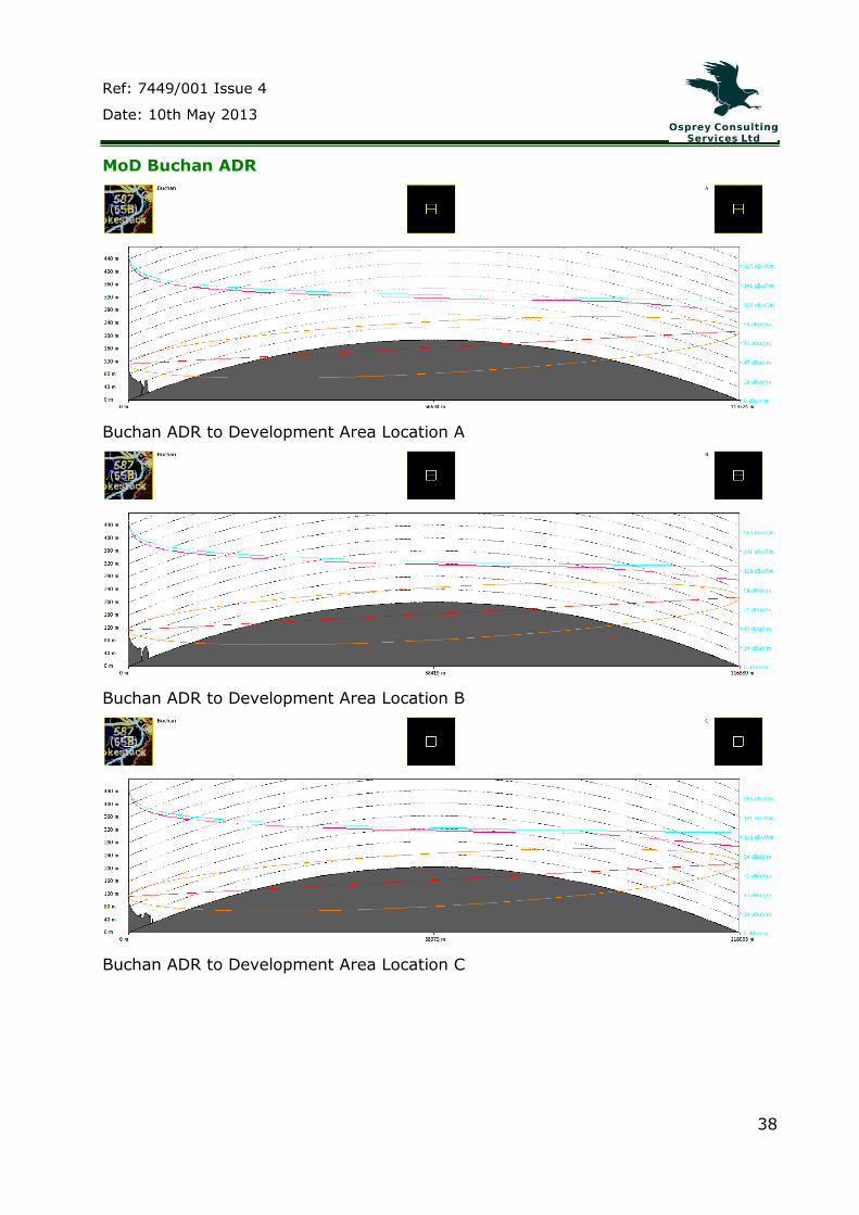
38
MoD Buchan ADR
Buchan ADR to Development Area Location A
Buchan ADR to Development Area Location B
Buchan ADR to Development Area Location C

Ref: 7449/001 Issue 4
Date: 10th May 2013
39
Buchan ADR to Development Area Location D
Buchan ADR to Development Area Location E
Buchan ADR to Development Area Location F

Ref: 7449/001 Issue 4
Date: 10th May 2013
40
Buchan ADR to Development Area Location G
Buchan ADR to Development Area Location H
Buchan ADR to Development Area Location I
Ref: 7449/001 Issue 4
Date: 10th May 2013
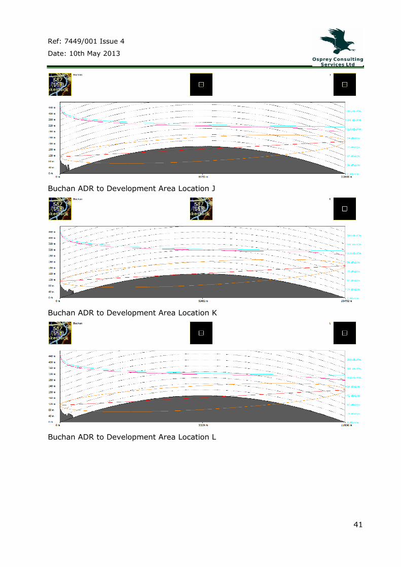
41
Buchan ADR to Development Area Location J
Buchan ADR to Development Area Location K
Buchan ADR to Development Area Location L
Ref: 7449/001 Issue 4
Date: 10th May 2013
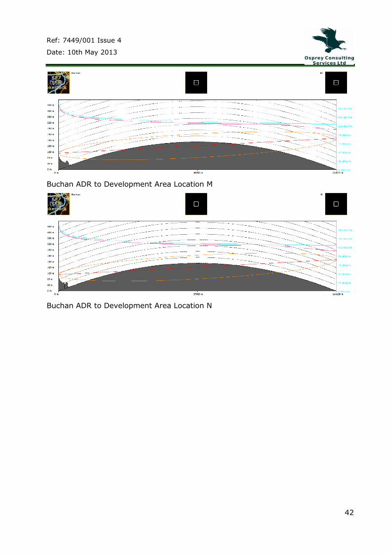
42
Buchan ADR to Development Area Location M
Buchan ADR to Development Area Location N

Ref: 7449/001 Issue 4
Date: 10th May 2013
43
MoD Brizlee Wood ADR
Brizlee Wood ADR to Development Area Location A
Brizlee Wood ADR to Development Area Location B
Brizlee Wood ADR to Development Area Location C

Ref: 7449/001 Issue 4
Date: 10th May 2013
44
Brizlee Wood ADR to Development Area Location D
Brizlee Wood ADR to Development Area Location E
Brizlee Wood ADR to Development Area Location F
Ref: 7449/001 Issue 4
Date: 10th May 2013
45
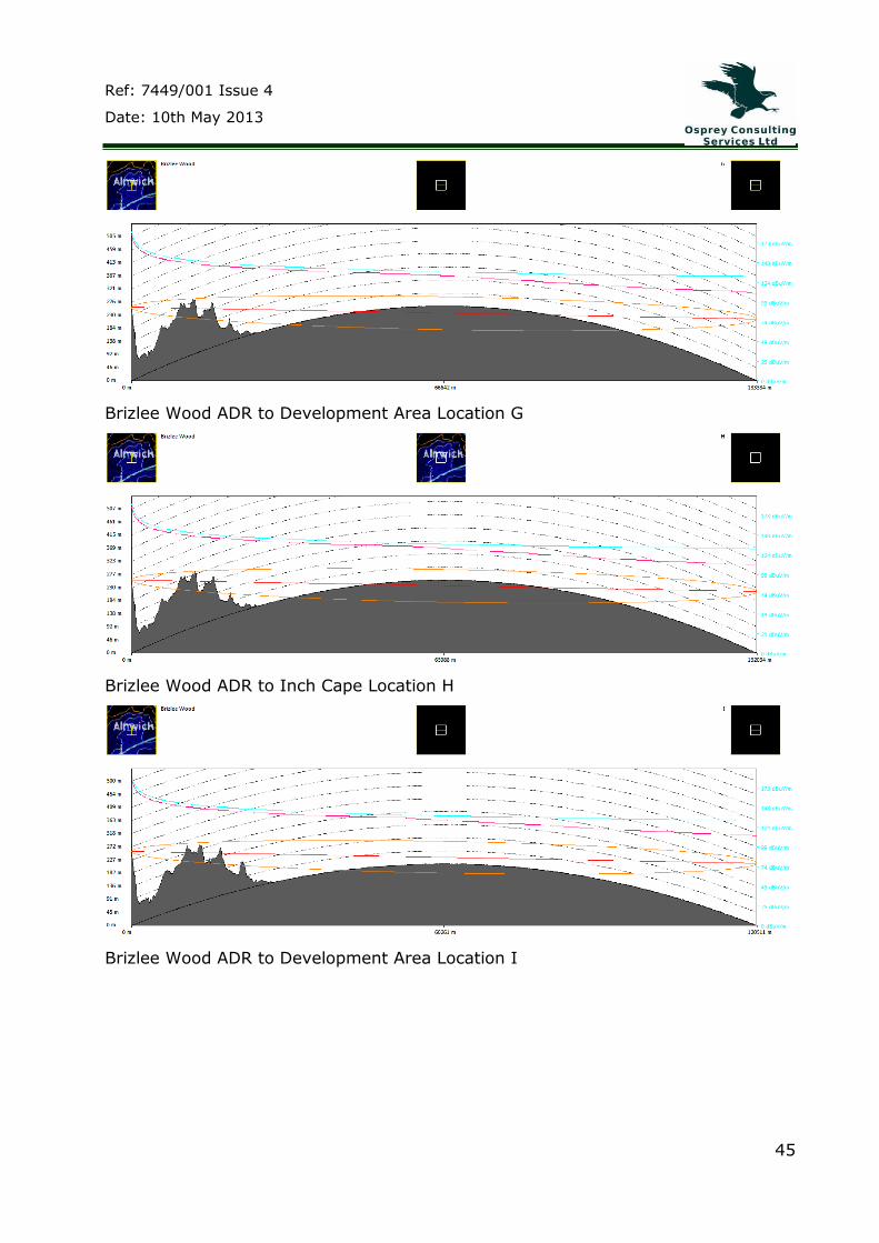
Brizlee Wood ADR to Development Area Location G
Brizlee Wood ADR to Inch Cape Location H
Brizlee Wood ADR to Development Area Location I

Ref: 7449/001 Issue 4
Date: 10th May 2013
46
Brizlee Wood ADR to Development Area Location J
Brizlee Wood ADR to Development Area Location K
Brizlee Wood ADR to Development Area Location L
Ref: 7449/001 Issue 4
Date: 10th May 2013
47
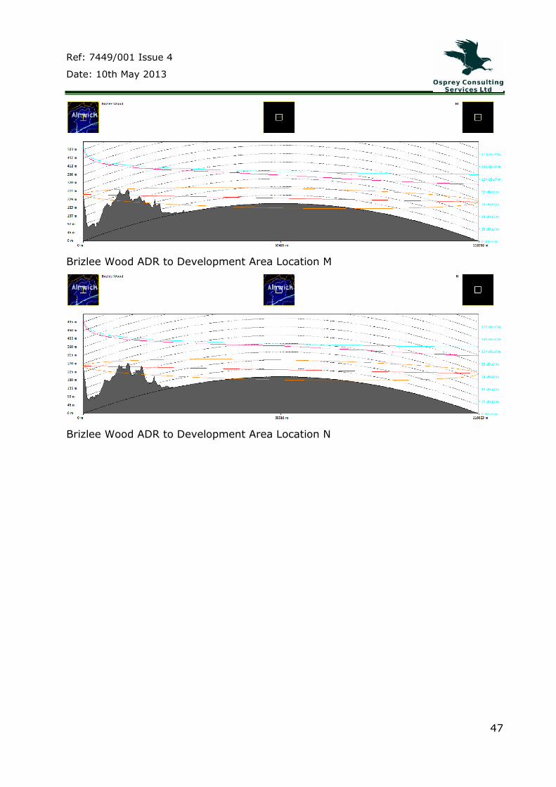
Brizlee Wood ADR to Development Area Location M
Brizlee Wood ADR to Development Area Location N