OSPF: Open Shortest Path First - Web Hosting Default...
71
1 OSPF: Open Shortest Path First 14.5 14.5
Transcript of OSPF: Open Shortest Path First - Web Hosting Default...

1
OSPF:Open Shortest
Path First
14.514.5

2
Figure 14-19
Areas in an autonomous system

3
Figure 14-20
Types of links

4
Figure 14-21
Point-to-point link

5
Figure 14-22
Transient link

6
Figure 14-23
Stub link

7
Figure 14-24a
Example of an AS

8
Figure 14-24b
Graphical representation of an AS

9

10
Shortest path calculation
Dijkstra’s Algorithm shortest path tree is created by each router.

11
Shortest path calculation

12
Shortest path calculation

13
OSPF Hello Protocol
• OSPF routers use the Hello Protocol to learn aboutother routers with interfaces on the same network(“neighbors”)
• On all multi-access networks (broadcast andnonbroadcast) the Hello Protocol also elects aDesignated Router
HELLO
HELLOHELLO

14
Neighbors and Adjacency
• OSPF creates adjacencies between neighborsto facilitate exchange of routing information
• Neighbors on point-to-point networks andvirtual links always become adjacent
• On multi-access networks, all routers becomeadjacent to the Designated Router
• Adjacencies control the distribution of routingprotocol packets

15
OSPF Designated Router
• Each multi-access network has a DesignatedRouter, elected by the Hello Protocol
• The Designated Router generates Link StateAdvertisements (LSA) for the multi-accessnetwork and has other responsibilities in therunning of the protocol
• The Designated Router concept enables areduction in the number of adjacencies required
• The reduction in the number of adjacenciesreduces the amount of routing traffic and the sizeof the topological database

16
Link State Advertisements
• Link State Advertisements are flooded throughoutan area ensuring all routers in the area haveexactly the same topological database
• The topological database consists of the LSAsfrom each router belonging to the area
• From the topological database, each routercalculates a shortest-path tree, with itself as root
• This shortest-path tree in turn yields a routingtable for intra-area routing (inside area)

17
Inter-Area Routing (between areas)
• Each Area Border Router summarizes thetopology of its attached areas for transmission toall other Area Border Routers via the backbone
• This process allows all ABRs to calculate paths todestinations not contained in its attached areas
• ABRs then advertise these paths to its attachedareas to enable routing to other areas
18
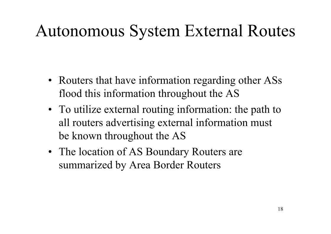
Autonomous System External Routes
• Routers that have information regarding other ASsflood this information throughout the AS
• To utilize external routing information: the path toall routers advertising external information mustbe known throughout the AS
• The location of AS Boundary Routers aresummarized by Area Border Routers

19
Figure 14-25
Types of OSPF packets

20
Open Shortest Path First
First OSPF RFC Oct 1989Final RFC 2328 April 1998
OSPF Components 1) Hello Protocol - Detect neighbors and confirm still there 2) “Reliable Flooding” Mechanism - ensures all routers in an OSPF area have a consistent link state database
OSPF is “Encapsulated” in IP and the IP protocol field is set to 0X59. Immediately following the IP header is a common 24 - Byte packet header.
1 2 30 1 2 3 4 5 6 7 8 9 0 1 2 3 4 5 6 7 8 9 0 1 2 3 4 5 6 7 8 9 0 1+-+-+-+-+-+-+-+-+-+-+-+-+-+-+-+-+-+-+-+-+-+-+-+-+-+-+-+-+-+-+-+-+-+-+-+
+-+-+-+-+-+-+-+-+-+-+-+-+-+-+-+-+-+-+-+-+-+-+-+-+-+-+-+-+-+-+-+-+-+-+-+
+-+-+-+-+-+-+-+-+-+-+-+-+-+-+-+-+-+-+-+-+-+-+-+-+-+-+-+-+-+-+-+-+-+-+-+
+-+-+-+-+-+-+-+-+-+-+-+-+-+-+-+-+-+-+-+-+-+-+-+-+-+-+-+-+-+-+-+-+-+-+-+
+-+-+-+-+-+-+-+-+-+-+-+-+-+-+-+-+-+-+-+-+-+-+-+-+-+-+-+-+-+-+-+-+-+-+-+
+-+-+-+-+-+-+-+-+-+-+-+-+-+-+-+-+-+-+-+-+-+-+-+-+-+-+-+-+-+-+-+-+-+-+-+
+-+-+-+-+-+-+-+-+-+-+-+-+-+-+-+-+-+-+-+-+-+-+-+-+-+-+-+-+-+-+-+-+-+-+-+
Version Type Packet LengthRouter ID
Area IDChecksum Au Type
AuthenticationAuthentication
Only neighborsin same areaform adjacencies
Version : 2
Type Description
1 Hello 2 Database Description 3 Link State Request 4 Link State Update 5 Link State Acknowledgment
OSPF's common header.
Authenticationtype0=none1=password

21
OSPF packets areOSPF packets areencapsulated in IPencapsulated in IP datagrams datagrams..

22
Figure 14-26
OSPF Packet Header
Area ID

23
Hello Protocol
Destination address is always 224.0.0.5 which is multicast and is represented in Ethernet as 0X01-00-5E-00-00-05
This is a MAC layer multicast address. OSPF hellos are transmitted every 10 seconds ( By Default ).
If 4 hello intervals pass (40 seconds ) without hearing a hello from a neighbor that neighbor isdeclared to be down
Hello Protocol: 1. Advertises a router’s “Aliveness” 2. Verifies two - way connectivity 3. Avoids one - way connectivity 4. Elects designated and backup designated routers 5. Maintains OSPF adjacencies once established
OSPF hello protocol allows detection of one- way links. Protocol lists neighbor routers router ID’s inhello packets.
OSPF routers will not attempt to form an adjacency (IE Synchronize Link State Databases ) until theysee themselves as sharing a two way link ( and they are both members of the same IP prefix - IPaddress anded with mask )

24
1 2 3
0 1 2 3 4 5 6 7 8 9 0 1 2 3 4 5 6 7 8 9 0 1 2 3 4 5 6 7 8 9 0 1+-+-+-+-+-+-+-+-+-+-+-+-+-+-+-+-+-+-+-+-+-+-+-+-+-+-+-+-+-+-+-+-+-+-+-+
+-+-+-+-+-+-+-+-+-+-+-+-+-+-+-+-+-+-+-+-+-+-+-+-+-+-+-+-+-+-+-+-+-+-+-+
+-+-+-+-+-+-+-+-+-+-+-+-+-+-+-+-+-+-+-+-+-+-+-+-+-+-+-+-+-+-+-+-+-+-+-+
+-+-+-+-+-+-+-+-+-+-+-+-+-+-+-+-+-+-+-+-+-+-+-+-+-+-+-+-+-+-+-+-+-+-+-+
+-+-+-+-+-+-+-+-+-+-+-+-+-+-+-+-+-+-+-+-+-+-+-+-+-+-+-+-+-+-+-+-+-+-+-+
+-+-+-+-+-+-+-+-+-+-+-+-+-+-+-+-+-+-+-+-+-+-+-+-+-+-+-+-+-+-+-+-+-+-+-+
+-+-+-+-+-+-+-+-+-+-+-+-+-+-+-+-+-+-+-+-+-+-+-+-+-+-+-+-+-+-+-+-+-+-+-+
+-+-+-+-+-+-+-+-+-+-+-+-+-+-+-+-+-+-+-+-+-+-+-+-+-+-+-+-+-+-+-+-+-+-+-+
Example / 18 Network Mask 0XFF- FF- C0 - 00
HelloInterval Options Rtr Pri RouterDeadInterval
Designated Router IPBackup Designated Router IP
Neighbor
Neighbor
Typically 40 Secmust be same toform adjacency
IP HeaderNot Shown
CommonOSPFHeaderNot Shown
Typical 10 Secmust be sameto form adjacency
OSPF HELLO PACKET
οο
Router Priority for DRelections

25
Figure 14-44
Hello packet

26
Hello packet’s network mask field is set by transmitting router to be the mask of theinterface on which the hello is being transmitted. Used by neighbors with transmitter routersource IP address to decide if within same prefix as transmitting router. If not will notattempt to form an OSPF adjacency.
Forming an OSPF adjacency means a pair of routers exchange, and maintain the commonlink state database.
Instead of every one doing this with every one we use a designated router ( DR ) and abackup designated router.
A new router learns about this from just one hello packet and forms an OSPF adjacencyonly with designated router, and back up designated router.
Multicast address 224.0.0.6 used to communicate updates to designated routers and backupdesignated routers. Then DR and BDR communicate to all others.

27
Designated Router and Backup Designated Router election.
Once elected DR and BDR remain even if a “Better” choice comes along.
The first router that is active on a LAN declares itself to be the DR after waiting “Router DeadInternal which is a field in hello packet.
DR fills in its own “ Router ID ” in the “Designated Router” field of hello packet.
Second router in LAN will become BDR after waiting “Router Dead Interval.”
If several routers all come on at the same time, router with the numerically largest “Router ID” willbecome DR, next higher BDR. (Router ID- A 32-bit number that uniquely identifies this router in the AS.One possible implementation strategy would be to use the smallest IP interface address belonging to the router.)
The “Router Priority” field in hello can be used to control who wins election 8 bits 0 to 255, higheris “Better” if set to 0 administrator never wants this router to become DR or BDR.
Typically value is set to 1.
Highest router priority used first, if several with same value, highest ID used next.

28
OSPF Scaling: Maximum # of Neighbors Per Router Interface (In one Hello Packet)
Given A Worst Case 60 Byte IP Header 24 Byte OSPF Header
20 Byte Hello Header
Given An MTU ( Maximum Transfer Unit ) 1500 Bytes
1500 - 60 - 24 - 20 = 1,396
It Takes 4 Bytes Per Neighbor Entry
1,396/4 = 349 Maximum number of neighbors that can fit into a single hello packet.

29
What do we mean by Reliable Flooding Algorithm?
Each update must be acknowledged so that the routers are sure that the change has beenreliably handed off to the next router.
Sending router retransmits until update has been acknowledged.
The entire process of spreading the update reliably over a spanning tree that includes allthe Area’s routers is known as the OSPF’s reliable flooding algorithm.

30
Types of LSAs

31
1 2 30 1 2 3 4 5 6 7 8 9 0 1 2 3 4 5 6 7 8 9 0 1 2 3 4 5 6 7 8 9 0 1+-+-+-+-+-+-+-+-+-+-+-+-+-+-+-+-+-+-+-+-+-+-+-+-+-+-+-+-+-+-+-+-+-+-+-+
+-+-+-+-+-+-+-+-+-+-+-+-+-+-+-+-+-+-+-+-+-+-+-+-+-+-+-+-+-+-+-+-+-+-+-+
+-+-+-+-+-+-+-+-+-+-+-+-+-+-+-+-+-+-+-+-+-+-+-+-+-+-+-+-+-+-+-+-+-+-+-+
+-+-+-+-+-+-+-+-+-+-+-+-+-+-+-+-+-+-+-+-+-+-+-+-+-+-+-+-+-+-+-+-+-+-+-+
+-+-+-+-+-+-+-+-+-+-+-+-+-+-+-+-+-+-+-+-+-+-+-+-+-+-+-+-+-+-+-+-+-+-+-+
+-+-+-+-+-+-+-+-+-+-+-+-+-+-+-+-+-+-+-+-+-+-+-+-+-+-+-+-+-+-+-+-+-+-+-+
Link State Advertisement (LSA) Packets Common Part
LS Age Options LS Type
Link State ID (1=>IP router, 2=>IP desig. Rtr, 3=>net addr, 4=>IP bndry rtr, 5=>IP AS bndry rtrAdvertising Router Router’s IDLS Sequence Number
LS Checksum Length
So newer LSA can over writeolder LSA
LS Age : 0x0000 - 0x0E10 ( i.e., 0-3600 ) seconds
LS Type Description
1 Router - LSA 2 Network - LSA 3 Summary - LSA (IP network) 4 Summary - LSA ( ASBR ) 5 AS - External - LSA
Common LSA header.
Aside: The entries in OSPF’s Link State Database are known as “Link State Advertisements”
Only live for max of one hour

32
Figure 14-28
LSA header

33
Figure 14-29Router link
From a router’s perspective: Advertises all the individual links’ networkaddresses. One address for each link connected to the router.

34
Figure 14-33
Network link
From an individual Network’s perspective: Advertises one network maskand all the router IP addresses connected to that individual network.

35
Figure 14-38
Summary link to network

36
Figure 14-40
Summary link to AS boundary router

37
Figure 14-42
External link

38
Types of LSAs

39
Example 3Example 3
In Figure 14.37 (next slide), which router(s)sends out router link LSAs?

40
Figure 14-37
Example 5 and Example 6

41
SolutionSolution
All routers advertise router link LSAs.
R1 has two links, Net1 and Net2.
R2 has one link, Net2 in this AS.
R3 has two links, Net2 and Net3.

42
1 2 30 1 2 3 4 5 6 7 8 9 0 1 2 3 4 5 6 7 8 9 0 1 2 3 4 5 6 7 8 9 0 1+-+-+-+-+-+-+-+-+-+-+-+-+-+-+-+-+-+-+-+-+-+-+-+-+-+-+-+-+-+-+-+-+-+-+-+
+-+-+-+-+-+-+-+-+-+-+-+-+-+-+-+-+-+-+-+-+-+-+-+-+-+-+-+-+-+-+-+-+-+-+-+
+-+-+-+-+-+-+-+-+-+-+-+-+-+-+-+-+-+-+-+-+-+-+-+-+-+-+-+-+-+-+-+-+-+-+-+
+-+-+-+-+-+-+-+-+-+-+-+-+-+-+-+-+-+-+-+-+-+-+-+-+-+-+-+-+-+-+-+-+-+-+-+
+-+-+-+-+-+-+-+-+-+-+-+-+-+-+-+-+-+-+-+-+-+-+-+-+-+-+-+-+-+-+-+-+-+-+-++=+=+=+=+=+=+=+=+=+=+=+=+=+=+=+=+=+=+=+=+=+=+=+=+=+=+=+=+
+-+-+-+-+-+-+-+-+-+-+-+-+-+-+-+-+-+-+-+-+-+-+-+-+-+-+-+-+-+-+-+-+-+-+-+
+-+-+-+-+-+-+-+-+-+-+-+-+-+-+-+-+-+-+-+-+-+-+-+-+-+-+-+-+-+-+-+-+-+-+-+
+-+-+-+-+-+-+-+-+-+-+-+-+-+-+-+-+-+-+-+-+-+-+-+-+-+-+-+-+-+-+-+-+-+-+-+
+-+-+-+-+-+-+-+-+-+-+-+-+-+-+-+-+-+-+-+-+-+-+-+-+-+-+-+-+-+-+-+-+-+-+-+
+-+-+-+-+-+-+-+-+-+-+-+-+-+-+-+-+-+-+-+-+-+-+-+-+-+-+-+-+-+-+-+-+-+-+-+
+-+-+-+-+-+-+-+-+-+-+-+-+-+-+-+-+-+-+-+-+-+-+-+-+-+-+-+-+-+-+-+-+-+-+-+
+-+-+-+-+-+-+-+-+-+-+-+-+-+-+-+-+-+-+-+-+-+-+-+-+-+-+-+-+-+-+-+-+-+-+-+
+-+-+-+-+-+-+-+-+-+-+-+-+-+-+-+-+-+-+-+-+-+-+-+-+-+-+-+-+-+-+-+-+-+-+-+
LS Age Options LS TypeLink State ID
Advertising Router
LS Sequence NumberLS Checksum Length
Link IDLink Data
Link Type # TOS Metrics Metric
Link Type # TOS Metrics Metric
Link IDLink Data
Sent out as zero. Routers that received this LSA keeptime by incrementing this field up to one hour at which point the entry is discarded
Router - LSA
Link 1
Link n
Link ID This is the network / subnet prefix
Link Data This is the mask for that prefix
Link State ID This is set to originating Routers Router ID also true for advertising Router field
Router-LSA.
οο
Number of LinksReserved

43
Router - LSA :
Link Type :
Stub Network => Link Type = 3 stub network is a network that is not used to reach destinationsbeyond the network itself.
Link ID = Network / Subnet “IP ” prefixLink Data = Mask for that prefix
Transit Network => Link Type = 2 transit network connect multiple OSPF routers
Link ID = Designated Router’s “Router ID”
Link Data = Router’s Interface IP address within that prefix.
Point to Point => Link Type = 1
Link ID = Address of Neighbor router
Link Data = Interface Number
In Router - LSA’s common LSA Header info: Link State ID and advertising router fields areboth set to the originating routers Router ID.

44
Figure 14-30
Router link LSA

45
ExampleExample
Give the router link LSA sent by router10.24.7.9 in next figure.

46
Example

47
SolutionSolution
This router has three links: two of type 1 (point-to-point) and one of type 3 (stub network). The nextfigure shows the router link LSA.

48
Solution to Example

49
Types of LSAs
50
Example 4Example 4
In next figure, which router(s) sends out thenetwork link LSAs?

51

52
SolutionSolution
All three networks must advertise network links:
Advertisement for Net1 is done by R1 because it isthe only router and therefore the designated router.
Advertisement for Net2 can be done by either R1,R2, or R3, depending on which one is chosen asthe designated router.
Advertisement for Net3 is done by R3 because it isthe only router and therefore the designated router.

53
Network - LSA : 1 2 30 1 2 3 4 5 6 7 8 9 0 1 2 3 4 5 6 7 8 9 0 1 2 3 4 5 6 7 8 9 0 1+-+-+-+-+-+-+-+-+-+-+-+-+-+-+-+-+-+-+-+-+-+-+-+-+-+-+-+-+-+-+-+-+-+-+-+
+-+-+-+-+-+-+-+-+-+-+-+-+-+-+-+-+-+-+-+-+-+-+-+-+-+-+-+-+-+-+-+-+-+-+-+
+-+-+-+-+-+-+-+-+-+-+-+-+-+-+-+-+-+-+-+-+-+-+-+-+-+-+-+-+-+-+-+-+-+-+-+
+-+-+-+-+-+-+-+-+-+-+-+-+-+-+-+-+-+-+-+-+-+-+-+-+-+-+-+-+-+-+-+-+-+-+-+
+-+-+-+-+-+-+-+-+-+-+-+-+-+-+-+-+-+-+-+-+-+-+-+-+-+-+-+-+-+-+-+-+-+-+-++=+=+=+=+=+=+=+=+=+=+=+=+=+=+=+=+=+=+=+=+=+=+=+=+=+=+=+=+
+-+-+-+-+-+-+-+-+-+-+-+-+-+-+-+-+-+-+-+-+-+-+-+-+-+-+-+-+-+-+-+-+-+-+-+
+-+-+-+-+-+-+-+-+-+-+-+-+-+-+-+-+-+-+-+-+-+-+-+-+-+-+-+-+-+-+-+-+-+-+-+
+-+-+-+-+-+-+-+-+-+-+-+-+-+-+-+-+-+-+-+-+-+-+-+-+-+-+-+-+-+-+-+-+-+-+-+
+-+-+-+-+-+-+-+-+-+-+-+-+-+-+-+-+-+-+-+-+-+-+-+-+-+-+-+-+-+-+-+-+-+-+-+
Network - LSA
Only originated by the Designated Router.
Listed routers ( Attached Routers ) will be those adjacent to the Designated Router.The Router ID along with both the Router - LSA’s and network LSA’s are used to determine the subnet prefixesattached to each router.
IN NETWORK - LSALink State ID = Originating routers interface address anded with network mask which is contained in “NetworkMask” field.
Attached router fields are other router interface addresses within that prefix.
LS Age Options LS Type (= 2)
Link State ID
Advertising Router
LS Sequence Number
LS Checksum LengthNetwork Mask
Attached Router 1
Attached Router n
οο

54
Figure 14-34
Network link advertisement format

55
Example 6Example 6
Give the network link LSA in Figure 13.44.

56
Figure 14-35
Example 4

57
SolutionSolution
The network, for which the network linkadvertises, has three routers attached. The LSAshows the mask and the router addresses. SeeFigure 14.36.
Note that only one of the routers, the designatedrouter, advertises the network link.

58
Figure 14-36
Solution to Example 4

59
Types of LSAs

60
Figure 14-38
Summary link to network

61
Outside of the OSPF area summary - LSA’s are used to advertise networks (but not exact connections) inside oneOSPF area to another adjacent area. (See Forouzan Figure 13-28 our slide 34)
1 2 30 1 2 3 4 5 6 7 8 9 0 1 2 3 4 5 6 7 8 9 0 1 2 3 4 5 6 7 8 9 0 1+-+-+-+-+-+-+-+-+-+-+-+-+-+-+-+-+-+-+-+-+-+-+-+-+-+-+-+-+-+-+-+-+-+-+-+
+-+-+-+-+-+-+-+-+-+-+-+-+-+-+-+-+-+-+-+-+-+-+-+-+-+-+-+-+-+-+-+-+-+-+-+
+-+-+-+-+-+-+-+-+-+-+-+-+-+-+-+-+-+-+-+-+-+-+-+-+-+-+-+-+-+-+-+-+-+-+-+
+-+-+-+-+-+-+-+-+-+-+-+-+-+-+-+-+-+-+-+-+-+-+-+-+-+-+-+-+-+-+-+-+-+-+-+
+-+-+-+-+-+-+-+-+-+-+-+-+-+-+-+-+-+-+-+-+-+-+-+-+-+-+-+-+-+-+-+-+-+-+-++=+=+=+=+=+=+=+=+=+=+=+=+=+=+=+=+=+=+=+=+=+=+=+=+=+=+=+=+
+-+-+-+-+-+-+-+-+-+-+-+-+-+-+-+-+-+-+-+-+-+-+-+-+-+-+-+-+-+-+-+-+-+-+-+
+-+-+-+-+-+-+-+-+-+-+-+-+-+-+-+-+-+-+-+-+-+-+-+-+-+-+-+-+-+-+-+-+-+-+-+
+-+-+-+-+-+-+-+-+-+-+-+-+-+-+-+-+-+-+-+-+-+-+-+-+-+-+-+-+-+-+-+-+-+-+-+
+-+-+-+-+-+-+-+-+-+-+-+-+-+-+-+-+-+-+-+-+-+-+-+-+-+-+-+-+-+-+-+-+-+-+-+
LS Age Options LS Type
Link State ID
Advertising RouterLS Sequence Number
LS Checksum Length
TOS 0 MetricTOS x TOS x Metric
( May add up to 6 TOS/TOS _ Metric pairs, as needed to describe this Link State ID)
Summary-LSA.
Only non zero TOS fields are used so first zero TOS Byte is end of summary-LSA packet.In practice TOS is not used so end after TOS X Metric field which is usually zero.
An area border router needs to originate one summary-LSA for each of its area’s reachable network prefixes. Only one network contained in each advertisement.
Aggregation of IP addresses may be used to reduce the number of summary-LSA’s that need to be injected into the backbone area, but only when an area boundary aligns with an IP address prefix.
< IP Prefix being advertised
Network Mask
Summary Link to Network LSA

62
Figure 14-39
Summary link to network LSA

63
Types of LSAs

64
Figure 14-40
Summary link to AS boundary router

65
Figure 14-41
Summary link to AS boundary LSA
Used to announce the route to an AS boundary router.

66
Types of LSAs

67
Figure 14-42
External link

68
Figure 14-43
External link LSA
Used to advertise networks that are outside the AS.

69
Figure 14-25
Types of OSPF packets

70
Figure 14-47
Link state acknowledgment packet

71
OSPF Summary
OSPF is never a bad choice over either version of RIP
RIPv2 at least supports VLSM and CIDR but is still a distance-vector protocol and converges slowly in large networks
Link state protocols converge much more quickly than distance-vector protocols especially as network size increases
In small networks there is probably no compelling reason to choose OSPF