OSHA Standard Compliant Pressure Relief 3-Port Valve
13
AC20-D AC30-D AC40-D AC40-06-D AC50-D VHS20-D VHS30-D VHS40-D VHS40-06-D VHS50-D Modular design with uniform body style to F.R.L units. Max. 75 % increase ∗1 Improved flow rate characteristics Energy saving Safety measure ∗1 VHS40-04-D Zero blow-by of the air during switching of the handle OSHA (Occupational Safety and Health Administration) standard compliant Variations Single action VHS20-D VHS30-D VHS40-D VHS40-06-D VHS50-D Double action VHS20W-D VHS30W-D VHS40W-D VHS40W-06-D VHS50W-D Port size (Rc, NPT, G) 1/8 1/4 3/8 1/2 3/4 1 ure re ety ty New New Single Action VHS20/30/40/50-D Series Double Action VHS20W/30W/40W/50W-D Series CAT.EUS13-12A-UK OSHA Standard Compliant Pressure Relief 3-Port Valve with Locking Holes RoHS
Transcript of OSHA Standard Compliant Pressure Relief 3-Port Valve

AC20-D AC30-D AC40-D AC40-06-D AC50-D
VHS20-D �
VHS30-D �
VHS40-D �
VHS40-06-D �
VHS50-D �
Modular design with uniform body style to F.R.L units.
Max. 75 % increase
∗1
Improved fl ow rate characteristics
Energy saving
Safety measure
∗1 VHS40-04-D
Zero blow-by of the air during switching of the handle
OSHA (Occupational Safety
and Health Administration)
standard compliant
VariationsSingle action VHS20-D VHS30-D VHS40-D VHS40-06-D VHS50-D
Double action VHS20W-D VHS30W-D VHS40W-D VHS40W-06-D VHS50W-D
Port size
(Rc, NPT, G)
1/8 �
1/4 � � �
3/8 � �
1/2 �
3/4 � �
1 �
urereetyty
NewNew
Single Action VHS20/30/40/50-D Series
Double Action VHS20W/30W/40W/50W-D SeriesCAT.EUS13-12A-UK
OSHA Standard CompliantPressure Relief 3-Port Valvewith Locking Holes
RoHS

Safety measure
With locking holes
Push the handle and then turn, 2-step action prevents malfunction.The supply/exhaust status of the air
fl ow can be verifi ed at a glance in
the indicator window.
When in the exhaust position, the valve may be padlock secured. Prevents accidental start-ups while personnel are cleaning or servicing equipment.
: Supply : ExhaustSUP EXH
Step 1Push down
the handle.
Turn the handle.
Step 2
Can prevent accidents caused by inadvertent air supply problems
VHS20-02-D
VHS30-03-D
VHS40-04-D
VHS50-10-D
Single Action VHS20/30/40/50-D Series
Double Action VHS20W/30W/40W/50W-D Series
Model Flow rate Q [l/min (ANR)]∗1 (IN --> OUT)
Existing model
Existing model
Existing model
Existing model
Max. 75 % increase
Shackle
diameter
∗ Recommended lock shackle diameter size: Ø 5 or more
For safety control, OSHA rule requires
energy sources for certain equipment
be turned off or disconnected and that
the device either be locked or labelled
with a warning tag.
When in the exhaust position, the valve may be padlock secured. Prevents accidental start-ups while personnel are cleaning or servicing equipment.
Improved fl ow rate characteristics
1484
3541
6746
14098
989
2274
3835
8270
With the indicator window
OSHA (Occupational Safety and Health Administration) standard compliant
Double action
50 %increase
55 %increase
75 %increase
70 %increase
∗1 These values have been calculated according to ISO 6358 and indicate the fl ow rate under standard conditions with an inlet pressure of 0.6 MPa (relative pressure) and a pressure drop of 0.1 MPa.
1
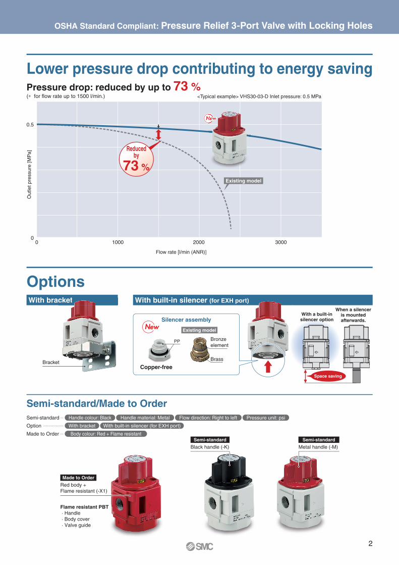
With bracket With built-in silencer (for EXH port)cket rt)
Options
Lower pressure drop contributing to energy saving
Semi-standard/Made to Order
Bracket
OSHA Standard Compliant: Pressure Relief 3-Port Valve with Locking Holes
Semi-standard … Handle colour: Black Handle material: Metal Flow direction: Right to left Pressure unit: psi
Option ……………… With bracket With built-in silencer (for EXH port)
Made to Order … Body colour: Red + Flame resistant
Pressure drop: reduced by up to 73 %
0.5
00 1000 2000 3000
Black handle (-K)
Red body +
Flame resistant (-X1)
Semi-standard
Made to Order
Semi-standard
Metal handle (-M)
Silencer assembly
Reducedby
73 %
Existing model
NewNew
Flame resistant PBT
· Handle
· Body cover
· Valve guide
PP
NeNeNewwwwwww
Existing model
(∗ for fl ow rate up to 1500 l/min.)
Outlet
pre
ssure
[M
Pa]
Flow rate [l/min (ANR)]
<Typical example> VHS30-03-D Inlet pressure: 0.5 MPa
Bronze
element
Brass
Copper-free
With a built-insilencer option
When a silenceris mountedafterwards.
Space saving
2

OSHA Standard Compliant Pressure Relief 3-Port Valve with Locking HolesSingle Action
VHS20/30/40/50-D Series
VHS20W/30W/40W/50W-D Series
How to Order
Double Action
3 1
2
q e r yw
· Option/Semi-standard: Select one each for a to f.
· Option/Semi-standard symbol:
When more than one specifi cation is required, indicate in
alphanumeric order.
Example) VHS30-N03-BS-RZ-Dt
VHS 30 03 D
Made to Order(For details, refer to page 8.)
Symbol Description�q
Body size
20 30 40 50
�w Handle operation— Single action � � � �
W Double action � � � �+
�e Pipe thread type
— Rc∗1 � � � �
N NPT � � � �
F G � � � �+
�r Port size
01 1/8 � — — —
02 1/4 � � � —
03 3/8 — � � —
04 1/2 — — � —
06 3/4 — — � �
10 1 — — — �+
�t
Op
tio
n
a Mounting— Without mounting option � � � �
B With bracket � � � �+
b Silencer— Without silencer � � � �
S With built-in silencer (for EXH port) � � � �+
�y
Se
mi-sta
nd
ard
c Handle colour— Red � � � �
K Black � � � �+
d Handle material— Resin � � � �
M Metal � � � �+
e Flow direction— Flow direction: Left to right � � � �
R Flow direction: Right to left � � � �+
f Pressure unit— Product label in SI units: MPa � � � �
Z∗2 Product label in imperial units: psi �∗3 �∗3 �∗3 �∗3
∗1 The pipe thread type for the EXH port is G.
∗2 For the pipe thread type: NPT only. This product is for overseas use only according to the New Measurement Act. (The SI unit type is provided for use in Japan.)
∗3 �: For the pipe thread type: NPT only
A system designed to respond quickly and easily to your special ordering needs
Short lead times
This system enables us to respond to your
special needs (additional machining, accessory
assembly, or the designing of a modular unit) and
deliver your personalised products as quickly as
standard products.
Repeat orders
Once we receive a simple special part num-
ber from one of your previous orders, we will
process the order, manufacture the product,
and deliver it to you as quickly as possible.
Simple Specials SystemFor modular connection units (shipped assembled), the simple specials system can be used.
Please contact your local sales representative for more details.
Symbol
3
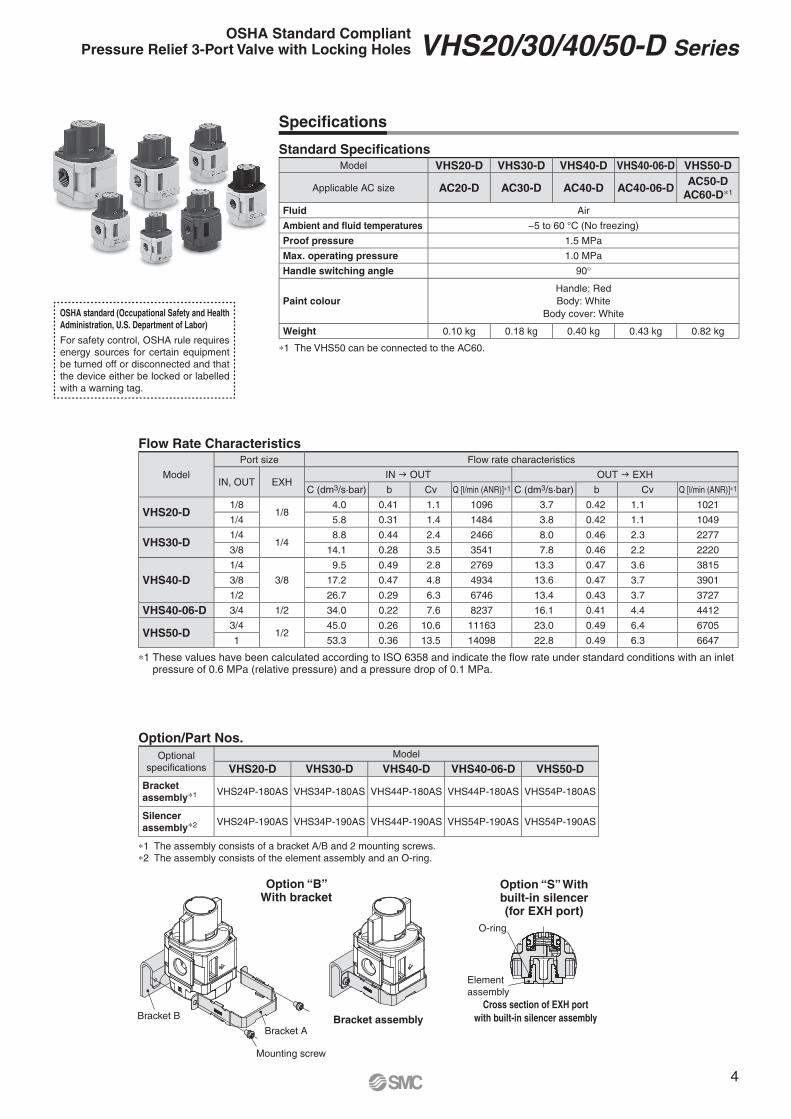
Flow Rate Characteristics
Standard Specifi cations
Option/Part Nos.
Specifi cations
Model VHS20-D VHS30-D VHS40-D VHS40-06-D VHS50-D
Applicable AC size AC20-D AC30-D AC40-D AC40-06-DAC50-D
AC60-D∗1
Fluid Air
Ambient and fluid temperatures −5 to 60 °C (No freezing)
Proof pressure 1.5 MPa
Max. operating pressure 1.0 MPa
Handle switching angle 90°
Paint colour
Handle: Red
Body: White
Body cover: White
Weight 0.10 kg 0.18 kg 0.40 kg 0.43 kg 0.82 kg
∗1 The VHS50 can be connected to the AC60.
Optional
specifi cations
Model
VHS20-D VHS30-D VHS40-D VHS40-06-D VHS50-D
Bracket
assembly∗1 VHS24P-180AS VHS34P-180AS VHS44P-180AS VHS44P-180AS VHS54P-180AS
Silencer
assembly∗2 VHS24P-190AS VHS34P-190AS VHS44P-190AS VHS54P-190AS VHS54P-190AS
∗1 The assembly consists of a bracket A/B and 2 mounting screws.
∗2 The assembly consists of the element assembly and an O-ring.
Model
Port size Flow rate characteristics
IN, OUT EXHIN OUT OUT EXH
C (dm3/s·bar) b Cv Q [l/min (ANR)]∗1 C (dm3/s·bar) b Cv Q [l/min (ANR)]∗1
VHS20-D1/8
1/84.0 0.41 1.1 1096 3.7 0.42 1.1 1021
1/4 5.8 0.31 1.4 1484 3.8 0.42 1.1 1049
VHS30-D1/4
1/48.8 0.44 2.4 2466 8.0 0.46 2.3 2277
3/8 14.1 0.28 3.5 3541 7.8 0.46 2.2 2220
VHS40-D
1/4
3/8
9.5 0.49 2.8 2769 13.3 0.47 3.6 3815
3/8 17.2 0.47 4.8 4934 13.6 0.47 3.7 3901
1/2 26.7 0.29 6.3 6746 13.4 0.43 3.7 3727
VHS40-06-D 3/4 1/2 34.0 0.22 7.6 8237 16.1 0.41 4.4 4412
VHS50-D3/4
1/245.0 0.26 10.6 11163 23.0 0.49 6.4 6705
1 53.3 0.36 13.5 14098 22.8 0.49 6.3 6647
OSHA standard (Occupational Safety and Health
Administration, U.S. Department of Labor)
For safety control, OSHA rule requires
energy sources for certain equipment
be turned off or disconnected and that
the device either be locked or labelled
with a warning tag.
∗1 These values have been calculated according to ISO 6358 and indicate the fl ow rate under standard conditions with an inlet pressure of 0.6 MPa (relative pressure) and a pressure drop of 0.1 MPa.
Option “B” With bracket
Option “S” With built-in silencer (for EXH port)
Bracket assembly
Cross section of EXH port
with built-in silencer assemblyBracket B
Bracket A
O-ring
Mounting screw
Element
assembly
4
OSHA Standard CompliantPressure Relief 3-Port Valve with Locking Holes VHS20/30/40/50-D Series

Dimensions
Dimensions [mm]
Model
Options specifications
With bracket With silencer
K L M N Q R S T U V W
VHS20-D 30 25.3 34 5.4 8.4 27 60 40 2.3 3 13
VHS30-D 41 33 43 6.5 10 36.5 71 50 2.3 3 17
VHS40-D 50 44 57 8.5 19 43.5 88 66 2.3 3 21
VHS40-06-D 50 46 59 8.5 19 43.5 88 68 2.3 4 27
VHS50-D 70 60 — 11 27.5 49.5 113 71 3.2 4 27
Model
Standard specifications
P1 P2A
B C D E F G H JSingle Double
VHS20-D 1/8, 1/4 1/8 48.5 51.7 23 40 37 28 42 17.5 40 21
VHS30-D 1/4, 3/8 1/4 55 58.2 32 53 49 38 53 20 53 26.5
VHS40-D 1/4, 3/8, 1/2 3/8 69.7 73.9 41.3 70 63 52 71 29 70 35.5
VHS40-06-D 3/4 1/2 71.7 75.9 43.3 75 63 52 71 29 70 35.5
VHS50-D 3/4, 1 1/2 86.5 90.7 44.5 90 80 72 90 33 90 45
Ø 1
0
Ø H
FGE
D
C
EXH
J K
2 x P1
TU
P2EXH
V
W
EXH
OUTIN
B
S
R
L
M
QN
SUP A
(Port size)
With built-in silencer
(Option)
Bracket
(Option)
(Port size)Width across fl ats
Key mounting position for
residual pressure exhaust
5
VHS20/30/40/50-D Series

VHS20/30/40/50-D Series
Modular Connection Example
Pressure relief 3-port valve VHS30-03-D 1 pc.
Spacer with bracket Y300T-D 4 pcs.
Air fi lter AF30-03-D 1 pc.
Common supply regulator with backfl ow function
AR30MK-0302E-D 2 pcs.
Regulator with backfl ow function AR30K-03E-D 1 pc.
Pressure relief 3-port valve VHS30-03-D 1 pc.
Spacer with bracket Y300T-D 2 pcs.
Filter regulator with backfl ow function AW30K-03E-D 1 pc.
Pressure switch with L-shaped piping adapter IS10L-30-03-D 1 pc.
L-shaped piping adapter E300L-03-D 1 pc.
Spacer with bracket Y300T-D 4 pcs.
Air fi lter AF30-03-D 1 pc.
Regulator AR30-03E1-D 1 pc.
Cross spacer Y34-03-D 1 pc.
Pressure relief 3-port valve VHS30-03-D 1 pc.
Combination example e
Combination example q
Combination example w
Pressure relief
3-port valve
Spacer with bracket Regulator with
backfl ow function
Air fi lter Common supply regulator with backfl ow function
For modular connection units (shipped assembled), the simple specials system can be used. For details, refer to page 3.
Please note that products do not come assembled. They should be ordered separately and assembled by the customer.
OUT
Pressure relief 3-port valve
Filter regulator with backfl ow function
Pressure switch with
L-shaped piping adapter
Spacer with bracket
Bypass port
Bypass port
IN
Pressure relief 3-port valve
RegulatorAir fi lter
L-shaped piping adapter
Spacer with bracket
Cross spacer
6
B
C
G
EE
EE
B
A A
K
D
F
H
ED C
J
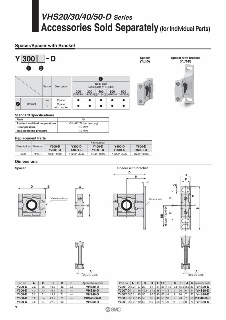
Spacer/Spacer with Bracket
Replacement Parts
Description Material
Part number
Y200-DY200T-D
Y300-DY300T-D
Y400-DY400T-D
Y500-DY500T-D
Y600-DY600T-D
Seal HNBR Y220P-050S Y320P-050S Y420P-050S Y520P-050S Y620P-050S
Part no. A B C D E EE F G H J K Applicable model
Y200T-D 3.2 67 29 51 24 33 11.5 5.5 15.5 3.5 30 VHS20-D
Y300T-D 4.2 85 42.5 67.5 35 — 14 7 20 6 41 VHS30-D
Y400T-D 5.2 115 50 85.5 40 55 18 9 26 7 50 VHS40-D
Y500T-D 5.2 115 50 85.5 40 55 18 9 26 7 50 VHS40-06-D
Y600T-D 6.2 140 60 115 50 70 20 11 31.2 8 70 VHS50-D
Part no. A B C D E Applicable model
Y200-D 3.2 35 13.2 42 0.6 VHS20-D
Y300-D 4.2 43 16.2 53 — VHS30-D
Y400-D 5.2 51 19.2 71 — VHS40-D
Y500-D 5.2 54 21.2 71 — VHS40-06-D
Y600-D 6.2 64 27.2 90 — VHS50-D
Symbol Description
�qBody size
[Applicable VHS size]
200[VHS20]
300[VHS30]
400[VHS40]
500[VHS40-06]
600[VHS50]
�w Bracket
— Spacer � � � � �
TSpacer
with bracket� � � � �
Standard Specifications
Fluid Air
Ambient and fl uid temperatures −5 to 60 °C (No freezing)
Proof pressure 1.5 MPa
Max. operating pressure 1.0 MPa
q w
Y 300 D
Dimensions
Spacer
(Y�-D)
Spacer with bracket
(Y�T-D)
Spacer Spacer with bracket
VHS20/30/40/50-D Series
Accessories Sold Separately (for Individual Parts)
Center of body
(Exc
ept Y
300T
-D)
Center of body
(Spacer width) (Spacer width)
7

qBody Colour: Red + Flame Resistant
VHS 30 03 D X1
Symbol Description
�qBody size
20 30 40 50
�w Handle operation— Single action � � � �
W Double action � � � �
+
�e Pipe thread type
— Rc∗1 � � � �
N NPT � � � �
F G � � � �
+
�r Port size
01 1/8 � — — —
02 1/4 � � � —
03 3/8 — � � —
04 1/2 — — � —
06 3/4 — — � �
10 1 — — — �
+
�t
Op
tio
n
a Mounting— Without mounting option � � � �
B With bracket � � � �
+
b Silencer— Without silencer � � � �
S With built-in silencer (for EXH port) � � � �
+
�y
Sem
i-sta
nd
ard
c Handle colour— Red � � � �
K Black � � � �
+
d Handle material— Resin � � � �
M Metal � � � �
+
e Flow direction— Flow direction: Left to right � � � �
R Flow direction: Right to left � � � �
+
f Pressure unit— Product label in SI units: MPa � � � �
Z∗2 Product label in imperial units: psi �∗3 �∗3 �∗3 �∗3
∗1 The pipe thread type for the EXH port is G.
∗2 For the pipe thread type: NPT only. This product is for overseas use only according to the New Measurement Act. (The SI unit type is provided for use in Japan.)
∗3 �: For the pipe thread type: NPT only
8
The body colour is red. Flame resistant resin is used for the exterior parts.
· Option/Semi-standard: Select one each for a to f.
· Option/Semi-standard symbol: When more than one specifi cation is required, indicate in alphanumeric order.
Example) VHS30-N03-BS-RZ-D-X1
q w t ye r Red body + Flame resistant
VHS20/30/40/50-D Series
Made to OrderPlease contact SMC for detailed dimensions, specifi cations, and delivery times.

Piping
Warning1. Piping load and moment
Avoid any torsional or bending moments other than those
caused by the equipment’s own weight as failure to do so may
result in damage.
Support external piping separately.
If moment application is unavoidable during operation, the
moment should be lower than the max. moment shown below.
Piping materials without flexibility, such as steel tube piping,
are prone to being affected by excess moment loads or
vibrations from the piping side. Use flexible tubing in between
to avoid such effects.
Unit: N·m
Applicable
modelVHS20[AC20]
VHS30[AC30]
VHS40[AC40]
VHS40-06[AC40-06]
VHS50[AC50/AC60]
Max. moment
(M)14.5 16 19.5 35 45
Max. moment (M) = Length (L) x Load (F)
2. Before piping is connected, the pipes should be
thoroughly blown through with air (fl ushing) or
washed to remove chips, cutting oil and other
debris from inside.
Should they remain, they could cause a malfunction.
3. When connecting pipes and fi ttings, etc., be sure
that neither chips from the pipe threads nor sealing
material get inside the valve.
When using sealant tape, leave 1.5 to 2 thread ridges
exposed at the end of the pipe/fi tting.
4. Connect piping/fi ttings using the recommended
torque while holding the female thread side tightly.
Insuffi cient tightening torque can result in loose piping or
sealing failure. Over tightening may break the thread. If the
female side is not held while tightening, excessive force will be
applied to the bracket directly, resulting in breakage.
Recommended Tightening Torque Unit: N·m
Connection thread 1/8 1/4 3/8 1/2 3/4 1
Torque 7 to 9 12 to 14 22 to 24 28 to 30 28 to 30 36 to 38
Precautions on Design
Warning1. Do not supply air pressure from ports other than
the 1 (P) port.
The valve will malfunction when air pressure is supplied from
other ports.
2. We recommend using a lock with a shackle
diameter of Ø 5 or more. If a lock with a shackle
diameter of less than Ø 5 is to be used, please test
it on the actual machine.
Installation and Adjustment
Caution1. The valve must be switched to each position
instantly and securely. Stopping the handle
between the extreme positions may cause a
malfunction.
2. Double action type requires two actions (push the
handle and turn it). Confi rm that the handle is
pushed properly before turning it. If the handle is
not pushed properly to the end, the internal parts
will be broken by turning the handle.
3. Tighten the 2 holding screws on the spacer with
bracket or spacer evenly.
Tighten them to the recommended tightening torque.
Insufficient tightening torque may result in loosening or sealing
failure. Excessive tightening torque may damage the thread,
etc.
Recommended Tightening Torque Unit: N·m
Applicable
modelVHS20[AC20]
VHS30[AC30]
VHS40[AC40]
VHS40-06[AC40-06]
VHS50[AC50/AC60]
Spacer with bracket
part numberY200T-D Y300T-D Y400T-D Y500T-D Y600T-D
Spacer part number Y200-D Y300-D Y400-D Y500-D Y600-D
Torque0.36
±0.036
1.2
±0.05
1.2
±0.05
1.4
±0.05
2.0
±0.1
VHS20/30/40/50-D Series
Specifi c Product Precautions 1Be sure to read this before handling the products. Refer to the back cover for safety instructions. For 3/4/5-port solenoid valve precautions, refer to the “Handling Precautions for SMC Products” and the “Operation Manual” on the SMC website: https://www.smcworld.com
Length (L)
Load (F)
Spacer with bracket
Holding screw
9
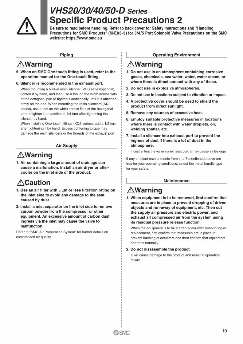
Operating Environment
Warning1. Do not use in an atmosphere containing corrosive
gases, chemicals, sea water, water, water steam, or
where there is direct contact with any of these.
2. Do not use in explosive atmospheres.
3. Do not use in locations subject to vibration or impact.
4. A protective cover should be used to shield the
product from direct sunlight.
5. Remove any sources of excessive heat.
6. Employ suitable protective measures in locations
where there is contact with water droplets, oil,
welding spatter, etc.
7. Install a silencer into exhaust port to prevent the
ingress of dust if there is a lot of dust in the
atmosphere.
If dust enters the valve via exhaust port, it may cause air leakage.
If any ambient environments from 1 to 7 mentioned above are
true for your operating conditions, select the metal handle type
for your safety.
Maintenance
Warning1. When equipment is to be removed, fi rst confi rm that
measures are in place to prevent dropping of driven
objects and run-away of equipment, etc. Then cut
the supply air pressure and electric power, and
exhaust all compressed air from the system using
its residual pressure release function.
When the equipment is to be started again after remounting or
replacement, fi rst confi rm that measures are in place to
prevent lurching of actuators and then confi rm that equipment
operates normally.
2. Do not disassemble the product.
It will cause damage to the product and result in operation
failure.
Piping
Warning5. When an SMC One-touch fitting is used, refer to the
operation manual for the One-touch fitting.
6. Silencer is recommended in the exhaust port.
When mounting a built-in resin silencer (VHS series/optional),
tighten it by hand, and then use a tool on the width across fl ats
of the octagonal part to tighten it additionally until it is attached
fi rmly on the end. When mounting the resin silencers (AN
series), use a tool on the width across fl ats of the hexagonal
part to tighten it an additional 1/4 turn after tightening the
silencer by hand.
When installing One-touch fi ttings (KQ2 series), add a 1/2 turn
after tightening it by hand. Excess tightening torque may
damage the resin silencers or the threads of the exhaust port.
Air Supply
Warning1. Air containing a large amount of drainage can
cause a malfunction. Install an air dryer or after-
cooler on the inlet side of the product.
Caution1. Use an air fi lter with 5 μm or less fi ltration rating on
the inlet side to avoid any damage to the seat
caused by dust.
2. Install a mist separator on the inlet side to remove
carbon powder from the compressor or other
equipment. An excessive amount of carbon dust
ingress via the inlet may cause the valve to
malfunction.
Refer to “SMC Air Preparation System” for further details on
compressed air quality.
VHS20/30/40/50-D Series
Specifi c Product Precautions 2Be sure to read before handling. Refer to back cover for Safety Instructions and "HandlingPrecautions for SMC Products" (M-E03-3) for 3/4/5 Port Solenoid Valve Precautions on the SMC website: https://www.smc.eu
10

These safety instructions are intended to prevent hazardous situations and/or equipment damage. These instructions indicate the level of potential hazard with the labels of “Caution,” “Warning” or “Danger.” They are all important notes for safety and must be followed in addition to International Standards (ISO/IEC) 1), and other safety regulations.
1) ISO 4414: Pneumatic fl uid power – General rules relating to systems.ISO 4413: Hydraulic fl uid power – General rules relating to systems.IEC 60204-1: Safety of machinery – Electrical equipment of machines.
(Part 1: General requirements)ISO 10218-1: Manipulating industrial robots - Safety.etc.
Safety Instructions
Caution:Caution indicates a hazard with a low level of risk which, if not avoided, could result in minor or moderate injury.
Warning:Warning indicates a hazard with a medium level of risk which, if not avoided, could result in death or serious injury.
Danger:Danger indicates a hazard with a high level of risk which, if not avoided, will result in death or serious injury.
Caution1. The product is provided for use in manufacturing industries.
The product herein described is basically provided for peaceful use in manufacturing industries. If considering using the product in other industries, consult SMC beforehand and exchange specifi cations or a contract if necessary.If anything is unclear, contact your nearest sales branch.
CautionSMC products are not intended for use as instruments
for legal metrology.
Measurement instruments that SMC manufactures or sells have not been qualifi ed by type approval tests relevant to the metrology (measurement) laws of each country.Therefore, SMC products cannot be used for business or certifi cation ordained by the metrology (measurement) laws of each country.
Limited warranty and
Disclaimer/ Compliance
RequirementsThe product used is subject to the following “Limited warranty and Disclaimer” and “Compliance Requirements”. Read and accept them before using the product.
Limited warranty and Disclaimer1. The warranty period of the product is 1 year in service or 1.5
years after the product is delivered, whichever is fi rst. 2) Also, the product may have specifi ed durability, running distance or replacement parts. Please consult your nearest sales branch.
2. For any failure or damage reported within the warranty period which is clearly our responsibility, a replacement product or necessary parts will be provided. This limited warranty applies only to our product independently, and not to any other damage incurred due to the failure of the product.
3. Prior to using SMC products, please read and understand the warranty terms and disclaimers noted in the specifi ed catalogue for the particular products.
2) Vacuum pads are excluded from this 1 year warranty.A vacuum pad is a consumable part, so it is warranted for a year after it is delivered. Also, even within the warranty period, the wear of a product due to the use of the vacuum pad or failure due to the deterioration of rubber material are not covered by the limited warranty.
Compliance Requirements1. The use of SMC products with production equipment for the
manufacture of weapons of mass destruction (WMD) or any other weapon is strictly prohibited.
2. The exports of SMC products or technology from one country to another are governed by the relevant security laws and regulations of the countries involved in the transaction. Prior to the shipment of a SMC product to another country, assure that all local rules governing that export are known and followed.
Safety Instructions Be sure to read “Handling Precautions for SMC Products” (M-E03-3) before using.
Warning1. The compatibility of the product is the responsibility of the person
who designs the equipment or decides its specifi cations.
Since the product specifi ed here is used under various operating conditions, its compatibility with specifi c equipment must be decided by the person who designs the equipment or decides its specifi cations based on necessary analysis and test results. The expected performance and safety assurance of the equipment will be the responsibility of the person who has determined its compatibility with the product. This person should also continuously review all specifi cations of the product referring to its latest catalogue information, with a view to giving due consideration to any possibility of equipment failure when confi guring the equipment.
2. Only personnel with appropriate training should operate machinery
and equipment.
The product specifi ed here may become unsafe if handled incorrectly. The assembly, operation and maintenance of machines or equipment including our products must be performed by an operator who is appropriately trained and experienced.
3. Do not service or attempt to remove product and machinery/
equipment until safety is confi rmed.
1. The inspection and maintenance of machinery/equipment should only be performed after measures to prevent falling or runaway of the driven objects have been confi rmed.
2. When the product is to be removed, confi rm that the safety measures as mentioned above are implemented and the power from any appropriate source is cut, and read and understand the specifi c product precautions of all relevant products carefully.
3. Before machinery/equipment is restarted, take measures to prevent unexpected operation and malfunction.
4. Contact SMC beforehand and take special consideration of safety
measures if the product is to be used in any of the following
conditions.
1. Conditions and environments outside of the given specifi cations, or use outdoors or in a place exposed to direct sunlight.
2. Installation on equipment in conjunction with atomic energy, railways, air navigation, space, shipping, vehicles, military, medical treatment, combustion and recreation, or equipment in contact with food and beverages, emergency stop circuits, clutch and brake circuits in press applications, safety equipment or other applications unsuitable for the standard specifi cations described in the product catalogue.
3. An application which could have negative effects on people, property, or animals requiring special safety analysis.
4. Use in an interlock circuit, which requires the provision of double interlock for possible failure by using a mechanical protective function, and periodical checks to confi rm proper operation.

Specifi cations are subject to change without prior notice and any obligation on the part of the manufacturerPrinting ZU 00 Printed in Spain
SMC Corporation (Europe)Austria +43 (0)2262622800 www.smc.at offi [email protected] +32 (0)33551464 www.smc.be [email protected] +359 (0)2807670 www.smc.bg offi [email protected] Croatia +385 (0)13707288 www.smc.hr offi [email protected] Republic +420 541424611 www.smc.cz offi [email protected] Denmark +45 70252900 www.smcdk.com [email protected] Estonia +372 6510370 www.smcpneumatics.ee smc@[email protected] +358 207513513 www.smc.fi smcfi @smc.fi France +33 (0)164761000 www.smc-france.fr [email protected] +49 (0)61034020 www.smc.de [email protected] +30 210 2717265 www.smchellas.gr [email protected] +36 23513000 www.smc.hu offi [email protected] +353 (0)14039000 www.smcautomation.ie [email protected] +39 03990691 www.smcitalia.it [email protected] +371 67817700 www.smc.lv [email protected]
Lithuania +370 5 2308118 www.smclt.lt [email protected] +31 (0)205318888 www.smc.nl [email protected] +47 67129020 www.smc-norge.no [email protected] +48 222119600 www.smc.pl offi [email protected] +351 214724500 www.smc.eu [email protected] +40 213205111 www.smcromania.ro [email protected] +7 (812)3036600 www.smc.eu [email protected] +421 (0)413213212 www.smc.sk offi [email protected] +386 (0)73885412 www.smc.si offi [email protected] +34 945184100 www.smc.eu [email protected] +46 (0)86031240 www.smc.nu [email protected] +41 (0)523963131 www.smc.ch [email protected] +90 212 489 0 440 www.smcpnomatik.com.tr [email protected] UK +44 (0)845 121 5122 www.smc.uk [email protected]
South Africa +27 10 900 1233 www.smcza.co.za [email protected]