OSD SERIES DIRECT GAS-FIRED AIR HEATER INSTALLATION, OPERATION
26
OSD SERIES DIRECT GAS-FIRED AIR HEATER INSTALLATION, OPERATION AND MAINTENANCE MANUAL FOR USE ONLY IN PAINT SPRAY BOOTHS AND DRYING OVEN APPLICATIONS READ MANUAL CAREFULY BEFORE INSTALLING OR OPERATING THE FURNACE FOR YOUR SAFETY FOR YOUR SAFETY If you smell gas follow these instructions, The use and storage of gasoline or other flammable 1) Open windows. vapors and liquids in open containers in the 2) Do not touch electrical switches. vicinity of this appliance is hazardous. 3) Extinguish any open flame. 4) Call the gas supplier immediately. MODEL: SERIAL NUMBER: JOB: DATE OF INSTALLATION: WARNING IMPROPER INSTALLATION, ADJUSTMENT, SERVICE OR MAINTENANCE CAN CAUSE PROPERTY DAMAGE, INJURY OR DEATH. PLEASE READ THE INSTALLATION, OPERATING AND MAINTENANCE INSTRUCTION THOROUGHLY. *THIS UNIT IS TO BE SERVICED BY QUALIFIED PERSONNEL* **DO NOT TAMPER WITH THE UNIT OR CONTROLS** INSTALLER’S RESPONSIBILITY Installer please note: This equipment has been test fired and inspected. It has been shipped free from defects from our factory. However, during shipment and installation, problems such as loose wires, leaks or loose fasteners may occur. It is the installer’s responsibility to inspect and correct any problems that may be found. THIS EQUIPMENT SHALL BE INSTALLED AND WIRED IN ACCORDANCE WITH THE REGULATIONS OF THE NATIONAL BOARD OF FIRE UNDERWRITERS, CANADIAN ELECTRIC CODE AND LOCAL GOVERNING BODIES. THE INSTALLAION CODE FOR “GAS BURNING, APPLIANCES AND EQUIPMENT, CAN 1-B149”, AND APPLICALBLE PROVINCIAL REGULATIONS FOR THE CLASS, WHICH SHOULD BE FOLLOWED CAREFULLY IN ALL CASES. INSTALLER/SERVICE CONTRACTOR NAME: ADDRESS: TELEPHONE: CONTACT:
Transcript of OSD SERIES DIRECT GAS-FIRED AIR HEATER INSTALLATION, OPERATION
OSD SERIESDIRECT GAS-FIRED AIR HEATER
INSTALLATION, OPERATION AND MAINTENANCE MANUALFOR USE ONLY IN PAINT SPRAY BOOTHS AND DRYING OVEN APPLICATIONS
READ MANUAL CAREFULY BEFORE INSTALLINGOR OPERATING THE FURNACE
FOR YOUR SAFETY FOR YOUR SAFETYIf you smell gas follow these instructions, The use and storage of gasoline or other flammable1) Open windows. vapors and liquids in open containers in the 2) Do not touch electrical switches. vicinity of this appliance is hazardous.3) Extinguish any open flame.4) Call the gas supplier immediately.
MODEL: SERIAL NUMBER:
JOB: DATE OF INSTALLATION:
WARNINGIMPROPER INSTALLATION, ADJUSTMENT, SERVICE OR MAINTENANCE CAN
CAUSE PROPERTY DAMAGE, INJURY OR DEATH. PLEASE READ THEINSTALLATION, OPERATING AND MAINTENANCE INSTRUCTION
THOROUGHLY.
*THIS UNIT IS TO BE SERVICED BY QUALIFIED PERSONNEL***DO NOT TAMPER WITH THE UNIT OR CONTROLS**
INSTALLER’S RESPONSIBILITYInstaller please note: This equipment has been test fired and inspected. It has been shipped free from defects fromour factory. However, during shipment and installation, problems such as loose wires, leaks or loose fasteners may
occur. It is the installer’s responsibility to inspect and correct any problems that may be found.
THIS EQUIPMENT SHALL BE INSTALLED AND WIRED IN ACCORDANCE WITH THE REGULATIONS OFTHE NATIONAL BOARD OF FIRE UNDERWRITERS, CANADIAN ELECTRIC CODE AND LOCALGOVERNING BODIES. THE INSTALLAION CODE FOR “GAS BURNING, APPLIANCES ANDEQUIPMENT, CAN 1-B149”, AND APPLICALBLE PROVINCIAL REGULATIONS FOR THE CLASS, WHICHSHOULD BE FOLLOWED CAREFULLY IN ALL CASES.
INSTALLER/SERVICE CONTRACTOR
NAME:
ADDRESS:
TELEPHONE:
CONTACT:

1
GENERAL INFORMATION
GENERAL NOTES
This Direct Fired OSD Spray/Bake Unit, dual air dual temperature unit is designed to provide make up air to satisfy theexhaust requirement of the paint spray booth. 100% volume on the spray cycle and 50% volume on the dry cycle. Normaldischarge temperature on spray cycle is between 70� F and 80� F. Normal discharge temperature on dry cycle is between120� F and 180� F. The sequence of operation and wiring diagram are located in the weather housing on out door units andburner compartments of indoor unit.
WARNING
Fire or Explosion hazard can cause property damage, severe injury or death. Ensure that all air taken into the unit isfree from the presence of:
a) Flammable solids, liquids and gases.b) Explosive materials. Example: grain dust, coal dust, gun powder etc.c) Substance which may be come toxic when exposed to heat or passing through a gas flame.
INSTALLATION AND SERVICE INSTRUCTIONS
The information provided is a guide to the proper installation, operation and troubleshooting of the unit. Retain the manualas a reference for operation and maintenance personnel. Should contact with the factory be necessary, provide the unit modelnumber and serial number. Install and wire the equipment in accordance with the applicable national and local governingbodies codes. Authorities having jurisdiction should be consulted before making the installation. Local codes may requireadditional safety controls and/or interlocks.
UNIT LOCATION
Prior to locating the unit check with the authorities having jurisdiction. The unit should be located with clearance to openaccess doors and remove filters. Ensure that the unit is installed level. Provide adequate clearance on either side of the unitto service blower, bearings, motors, drives and filters. Ensure that the position of the heater relative to support beams iscorrect so as to provide adequate support for the equipment. For roof mounted units, check the spacing of the roof structurebeams to avoid interference with air ducts.
LOCATION OF ACCESSORIES
The remote panel will be shipped as a separate package. Mount the panel and have an electrical contractor install wiring.
FACTORY TESTING & START UP CHECKLIST
All OSD series units are factory fired and tested prior to shipping. Each unit is shipped with the tester’s report and a start-upchecklist. Complete the start-up checklist and return one copy to the factory.
2
INSPECTION OF EQUIPMENT
All shipments are made F.O.B. the factory. The unit is securely strapped or blocked to prevent shipping damage and eachshipment inspected prior to leaving the plant. All parts, where feasible, are strapped to or included in the unit. Upon receiptof goods, check the shipment against the bill of lading to ensure all items have been received. Carefully check the unit forphysical damage in the presence of the carrier’s representative. Should parts be missing or damage noted, file a claimimmediately with the carrier. ICE does not assume responsibility for the handling of the goods in transit and is notresponsible for the initiation of freight claims.
INSTALLATION AND SERVICE INSTRUCTIONS
Direct Gas Fired Air Heaters
LOCATION OF UNIT AND DISTRIBUTION
Inlet
The intake shall be designed and located to prevent snow, rain, flammable gas, toxic gases and other deleterious materialsfrom entering the unit. (Less than 500 F.P.M. is an accepted velocity.)
INSTALLATION
Smaller models are shipped as one total unit. All other models are shipped in sections that are easily erected on the job site.The main sections consist of a burner damper section that contains the motor, and a blower section. The secondary sectionsare the filter, louver, mixing box etc., which are added in sections as required.
1. All sections are pre-drilled and are bolted together in the field (as per Figure 1).2. Belts must be installed on the motor, and limit and discharge controls may have to be mounted and/or wired.3. When clearance is not a factor, ensure that the unit is adequately protected from obstruction.
NOTE: On roof top units the joints will have to be caulked to prevent rain from entering the unit.
Indoor Suspension
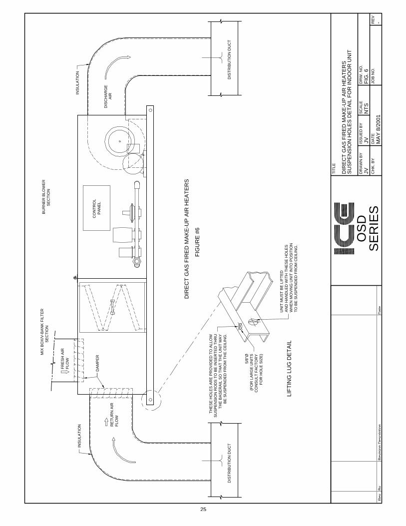
On indoor models holes at the base of the units are provided for 5/8” suspension rods (see Figure 6). Unit must be lifted andhandled from the lifting holes provided at each end of the channel iron, when suspending from the ceiling. If units are to belifted from the bottom for mounting on a platform (as with a forklift), unit must be supported.
NOTE: DO NOT LIFT CABINET WITHOUT THIS SUPPORT.
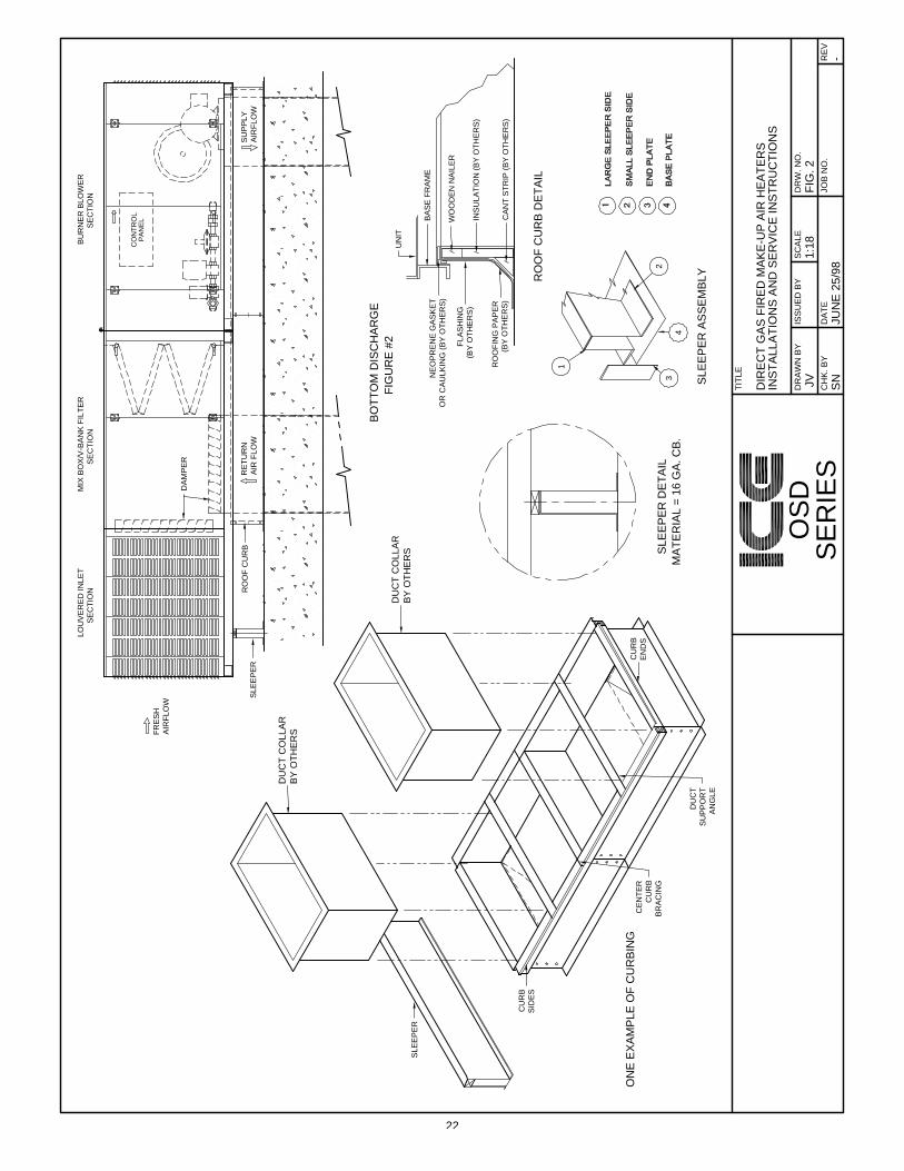
Rooftop Installation
Support rails (minimum of 4” high) must be provided underneath the unit. In some cases, more height may be required wheninstalling the supply duct through the roof (see Figure 1) or if a unit is a bottom discharge (see Figure 2).
Minimum clearance from the unit, to combustible construction, is clearly marked on the rating plate attached to the unit. No source of flammable vapors, gases or dust shall be with in 20’ horizontally of any unit unless that source is separated fromthe unit by an enclosure of fire and vapor resistive materials.
On indoor suspended units, when necessary to provide working clearance beneath the unit, the installation shall be made at asuitable height above the floor.
3
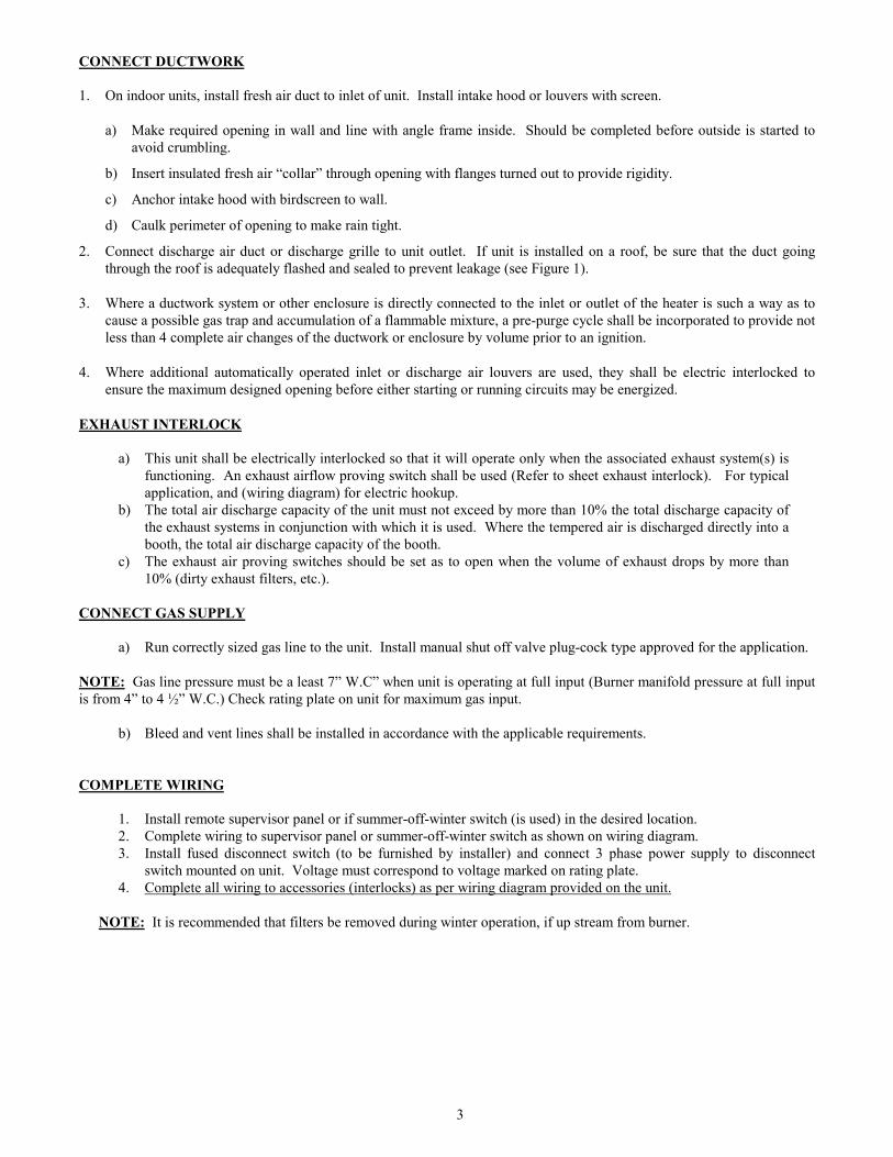
CONNECT DUCTWORK
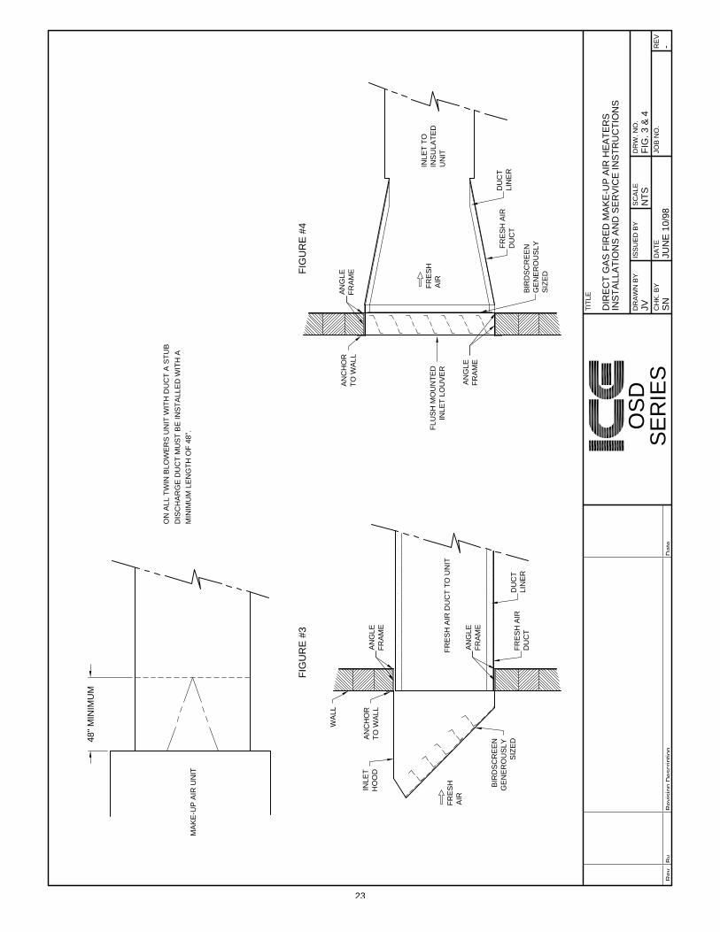
1. On indoor units, install fresh air duct to inlet of unit. Install intake hood or louvers with screen.
a) Make required opening in wall and line with angle frame inside. Should be completed before outside is started toavoid crumbling.
b) Insert insulated fresh air “collar” through opening with flanges turned out to provide rigidity.
c) Anchor intake hood with birdscreen to wall.
d) Caulk perimeter of opening to make rain tight.
2. Connect discharge air duct or discharge grille to unit outlet. If unit is installed on a roof, be sure that the duct goingthrough the roof is adequately flashed and sealed to prevent leakage (see Figure 1).
3. Where a ductwork system or other enclosure is directly connected to the inlet or outlet of the heater is such a way as tocause a possible gas trap and accumulation of a flammable mixture, a pre-purge cycle shall be incorporated to provide notless than 4 complete air changes of the ductwork or enclosure by volume prior to an ignition.
4. Where additional automatically operated inlet or discharge air louvers are used, they shall be electric interlocked toensure the maximum designed opening before either starting or running circuits may be energized.
EXHAUST INTERLOCK
a) This unit shall be electrically interlocked so that it will operate only when the associated exhaust system(s) isfunctioning. An exhaust airflow proving switch shall be used (Refer to sheet exhaust interlock). For typicalapplication, and (wiring diagram) for electric hookup.
b) The total air discharge capacity of the unit must not exceed by more than 10% the total discharge capacity ofthe exhaust systems in conjunction with which it is used. Where the tempered air is discharged directly into abooth, the total air discharge capacity of the booth.
c) The exhaust air proving switches should be set as to open when the volume of exhaust drops by more than10% (dirty exhaust filters, etc.).
CONNECT GAS SUPPLY
a) Run correctly sized gas line to the unit. Install manual shut off valve plug-cock type approved for the application.
NOTE: Gas line pressure must be a least 7” W.C” when unit is operating at full input (Burner manifold pressure at full inputis from 4” to 4 ½” W.C.) Check rating plate on unit for maximum gas input.
b) Bleed and vent lines shall be installed in accordance with the applicable requirements.
COMPLETE WIRING
1. Install remote supervisor panel or if summer-off-winter switch (is used) in the desired location.2. Complete wiring to supervisor panel or summer-off-winter switch as shown on wiring diagram.3. Install fused disconnect switch (to be furnished by installer) and connect 3 phase power supply to disconnect
switch mounted on unit. Voltage must correspond to voltage marked on rating plate.4. Complete all wiring to accessories (interlocks) as per wiring diagram provided on the unit.
NOTE: It is recommended that filters be removed during winter operation, if up stream from burner.

4
WARNING
FIRE OR EXPLOSION HAZARD CAN CAUSE PROPERTY DAMAGE, SEVERE INJURY, ORDEATH.
Check for gas leaks with rich soap and water solution any time work is done on a gas control.
START-UP PROCEDURE
1. Remove shipping blocks from:
a) Blower if rubber or spring isolated.b) Check to be sure that damper opens, if tied down, remove wire.c) Check modulating discharge controller, on units, to ensure that it is in the blower air stream. On some units this
control may be mounted external from the unit. If so, check to see that the sensor installed is the discharge air streamof the heater air and that the controller is wired to the modulating motor, regulating gas supply to burner.
2. Make sure that the main firing valve is closed, but that gas is available in the service line.
3. Check to ensure exhaust fans are wired into the control panel and that there is power to the exhaust starter relays.Check to ensure exhaust fans interlock switches are installed and wired to the control panel.
4. Familiarize yourself with the sequence of operation and wiring diagrams this will give you information as to how theunit operates in the paint and cure modes.
5. Check voltage to ensure it matches the voltage stamped on the unit rating plate, and all wires are connected betweenunit and remote panel.
6. The timers TD-1 - TD-5 are factory set but you should check them to ensure they have not moved during transit to jobsite.
a) Normal setting of high limits are paint mode -165�F cure mode -200�F auto reset.
7. Operate unit through paint mode by pushing in the system “on” push button. The unit should operate as per sequenceof operation.
a) Pilot
The Protector relay monitors the pilot flame through the flame rod. A minute current is sent from the relay throughthe flame rod, and trough the pilot flame to “ground”. The relay detects the current flow and acts to open the safetyvalve as required. When no flame exists, current cannot flow and the relay acts to close the valve. Current flowdepends only on flame contact on the rod: temperature of the rod is of no importance.
Since the flame rod is a current-carrying conductor, it must be free of any contact with conductive parts of the pilotburner. Insulator must be clean, dry and free from cracks. While the flame rod is made of a heat resistant alloy itmay, after long service, deteriorate to the point of flame contact. Check for serious corrosion or loss of metal. It mustbe tight enough in the insulator to maintain its position. Do not use too much force or the insulator may crack.
Proper operation of the flame rod can be checked by measuring the flame rod current; refer to flame safeguardinstruction sheet with unit. Lacking a micrometer, a check can be made with an operating burner through all itsnormal phases. Relay response should be prompt with no chattering or drop out.
The spark rod (Midco Burner see Figure 5 for gap setting, Maxon Burner spark ignitor No. 18075) produces a hightension arc at the correct location for lighting the pilot. Ignition transformer must be rated for 6000 Volts, 20Milliampers secondary, minimum.
The spark rod or spark ignitor, must be free of contact with conductive parts of the pilot burner. Insulator must beclean, dry and free of cracks. Check the spark rod for serious corrosion or loss of metal. It must be held tightlyenough is the insulator to maintain its position.

5
Gap must be 1/16” to 3/32” (see Figure 5). Setting can also be checked by cycling the pilot. Ignition must be promptand positive. Do not allow careless positioning to cause arc of flame rod; serious relay damage would result.
The spark ignitor on Maxon burners, if ignitor shows deterioration of ignitor points the complete spark ignitor shouldbe replaced part No. 18075.
8. If pilot tries for ignition, but locks out, the air proving switches (high and low) that are mounted across the profileplate, should be checked to make sure that the proper amount of air is flowing through the unit. Check to make sureblowers are running in the proper direction. This can be checked by placing a differential gauge across the profileplate of the burner section. If the pressure drop is between .30” W.C., and .95” W.C., these switches should be made,then check pilot to ensure proper flame. Check instruction sheet for flame safeguard system.
Pilot adjustment screw is in the Thermax shut-off valve. When setting, adjust for the best reading, then open pilot setscrew slightly.
a) Main flame supervision: With units that have more than three feet of burner from point or supervision, a secondflame rod will be on the main burner. This switching is done with a time delay relay. See wiring diagram. This canbe disconnected for testing for pilot, or you have to ensure main flame by opening up the firing valve within 15seconds after pilot solenoid is powered. As supervision will switch from pilot to main flame in that time. Check toensure that unit will lockout in the event of main flame failure on low-fire by closing main firing valve.
9. Gradually open firing valve to start main flame. Check for flame over entire burner length. Adjust the pressureregulator to 4” or 4 ½ ” W.C. pressure or the amount of gas marked on the rating plate.
10. All OSD units may have Maxitrol modulation. Read over the Maxitrol literature for the high fire and low fire setting.By removing the wire from #2 on the amplifier the unit will stay on low fire and allow you to set the by pass or lowfire setting to ensure that the flame is completely across burner and is between 1” and 1½ ” long (see literaturesupplied with unit).
11. To set up high fire you will require spray test resistor 1.10K, dry (cure) test resistor 1.21K. These are attached to theMaxitrol literature. These resistors should be placed across #3 and #4 of the amplifier on the unit (remove when testis complete).
a) Check gas pressure switch setting.
High pressure gas switch …………………………………..…… 6” W.C.Low pressure gas switch ………………………………….……. 2” W.C.
NOTE: The high and low gas pressure switches may be the manual reset type on some units.
FLAME SUPERVISION CHECK
a) The flame supervision should be checked periodically to insure that the controls are operational. With the uniton full operation and firing, close the main manual firing valve and pilot manual firing valve. This should lockout the unit.
b) The units with more than 3 feet of burner from the point of supervision have dual flame rod and a delay timer formain flame supervision. Closing the main firing valve should lock out the safety relay and the unit shouldshutdown.
c) The main safety valve should be checked for gas tightness by placing a manometer in the manifold between thesafety valve and the manual firing valve (a 1/8” plug is provided for this). If there is a build up of pressure withthe unit locked out and the manual valve closed, the safety valve should be replaced.
d) The complete gas line and manifold should be checked for gas tightness.

6
C.F.M.
a) This unit depends upon an adequate supply of air for good combustion and operation. Care should be taken toensure that properly sized inlet hood and ductwork are installed and that the unit is discharging the rightamount of CFM.
TROUBLE SHOOTING GUIDE
On start up, the unit will not operate properly. It may be an electrical mix up in the wire from the unit to the controlpanel (see wiring drawing).
The wire connector shown 12 are in the remote panel.The wire connector shown �12 are on the unit.It is recommended you have a volt meter AC/DC, and a differential pressure gauge 0” - 2”(magnehelic) and a gas pressure gauge 0” - 12”.
SPRAY MODE
1. If inlet damper fails to open when system switch is pushed in.
a) Check to see if power is on #4. If no power supply starter overloads (1 OLS-1), may be open R1-1normally closed contacts may be open. Main flame safe guard relay needs to be reset.
2. Fresh air damper open, but no power on #9.
a) Damper end switch open (DMES-1) reset.
3. High exhaust fan operating, no power on #13.
a) Check high exhaust fan inter lock switch.
4. If supply fan is not operating, check delay start timer (TD1) normally set at 3 seconds to allow for exhaust fanto come up to speed to keep the booth from over pressure and blow the doors open.
a) Balance exhaust and supply fan.
5. No power on #40.
a) Check summer/winter switch.
b) Spray high limit (HL-S).
c) Check air flow across burner with a magnehelic gauge to ensure proper air flow. Should be a differencebetween .45” and .65” W.C.
6. Power on #40, but burner will not come on.
a) Change flame safe guard relay.
7. Power on #40 burner tries to fire up but locks out.
a) Check pilot solenoid valve.
b) Check ignition transformer.
c) Check flame rod, if dirty clean, if cracked isolator replace.

7
8. Burner on low fire only.
a) Check TD2 timer low fire timer should be set at 20 seconds.
b) Check DC volts on #55 and #57, if above 5 V.D.C. modulation valve may be defective, replace.
9. See Maxitrol literature to trouble shoot the system.
NOTE: On custom built units the number designation may change. Carefully check wire diagram supplied with unit.
BAKE MODE
1. Purge light “off”, dry cycle light not “on”.
a) Check and replace.
2. Burner not on, no power on #40.
a) Check dry high limit (HL-B).b) Check low exhaust inter lock.c) Check high and low profile air switches.d) Check profile damper should be closed below burner.
3. Power on #40 burner not on. See instruction spray mode 5, 6, 7, and 8.
4. Burner on, but will not operate up to selector set point.
a) Check to see if temperature delay timer TD4 is powered and switch over from #12 to #11, on theMaxitrol, amplifier is completed.
b) Check discharge sensor.c) Refer to Maxitrol trouble shooting guide provided with this manual.
OPERATING PRINCIPLES OF THE RAW GAS BURNER
The raw gas burner is designed to operate in a duct of flowing fresh air. Fuel gas is fed directly to the burners; kineticenergy of the air stream furnishes combustion air. The burner must be installed to fire with, and parallel to, the airflow. By virtue of velocity impact and suction generated by the diverging shape of the combustion baffles, air isinduced into the air ports in the combustion zone. The air supply is constant though only that which mixes with the gasflowing from the burner ports, takes part in combustion.
When a very small quantity of gas is admitted to the burner, sufficient mixing takes place in the low fire slot within theburner, casting and combustion takes place in this zone. Since the low fire zone is contained within the burner castingit is effectively shielded from fire disrupting uncontrolled air entry.
As the gas is increased the flame progresses into the intermediate fire zone where an additional supply of air isavailable. High or full capacity, mixing occurs at the larger air ports of the high fire zone augmented by air spillingover the end of the baffles.
On a reduction of gas supply the reverse sequence takes place. The flame receding to a location of lesser air supplyuntil the low fire zone is reached. The system above is suitable for a turn down range of approximately 30 to 1.
With the suction by the blower there is a pressure in the gas manifold of less that zero at low fire. Therefore, whenchecking the manifold pressure you will find that the pressure will range from approximately 4” W.C. to less thanzero, when the unit is modulating from high to low fire.
8
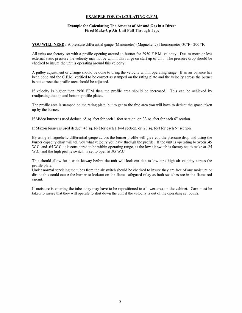
EXAMPLE FOR CALCULATING C.F.M.
Example for Calculating The Amount of Air and Gas in a Direct Fired Make-Up Air Unit Pull Through Type
YOU WILL NEED: A pressure differential gauge (Manometer) (Magnehelic) Thermometer -30�F - 200 �F.
All units are factory set with a profile opening around to burner for 2950 F.P.M. velocity. Due to more or lessexternal static pressure the velocity may not be within this range on start up of unit. The pressure drop should bechecked to insure the unit is operating around this velocity.
A pulley adjustment or change should be done to bring the velocity within operating range. If an air balance hasbeen done and the C.F.M. verified to be correct as stamped on the rating plate and the velocity across the burneris not correct the profile area should be adjusted.
If velocity is higher than 2950 FPM then the profile area should be increased. This can be achieved byreadjusting the top and bottom profile plates.
The profile area is stamped on the rating plate, but to get to the free area you will have to deduct the space takenup by the burner.
If Midco burner is used deduct .65 sq. feet for each 1 foot section, or .33 sq. feet for each 6” section.
If Maxon burner is used deduct .45 sq. feet for each 1 foot section, or .23 sq. feet for each 6” section.
By using a magnehelic differential gauge across the burner profile will give you the pressure drop and using theburner capacity chart will tell you what velocity you have through the profile. If the unit is operating between .45W.C. and .65 W.C. it is considered to be within operating range, as the low air switch is factory set to make at .25W.C. and the high profile switch is set to open at .95 W.C.
This should allow for a wide leeway before the unit will lock out due to low air / high air velocity across theprofile plate.Under normal servicing the tubes from the air switch should be checked to insure they are free of any moisture ordirt as this could cause the burner to lockout on the flame safeguard relay as both switches are in the flame rodcircuit.
If moisture is entering the tubes they may have to be repositioned to a lower area on the cabinet. Care must betaken to insure that they will operate to shut down the unit if the velocity is out of the operating set points.
9
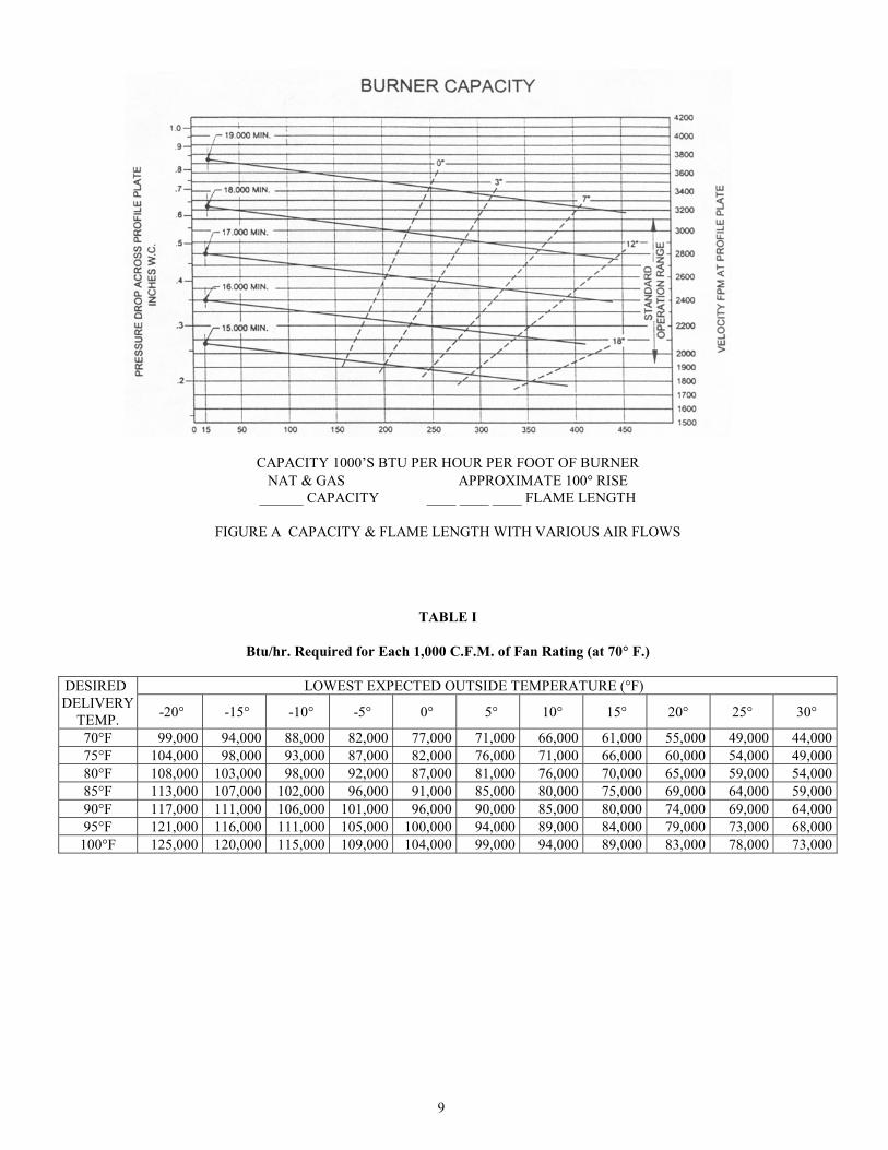
CAPACITY 1000’S BTU PER HOUR PER FOOT OF BURNERNAT & GAS APPROXIMATE 100� RISE
______ CAPACITY ____ ____ ____ FLAME LENGTH
FIGURE A CAPACITY & FLAME LENGTH WITH VARIOUS AIR FLOWS
TABLE I
Btu/hr. Required for Each 1,000 C.F.M. of Fan Rating (at 70� F.)
LOWEST EXPECTED OUTSIDE TEMPERATURE (°F)DESIREDDELIVERY
TEMP. -20° -15° -10° -5° 0° 5° 10° 15° 20° 25° 30°
70°F 99,000 94,000 88,000 82,000 77,000 71,000 66,000 61,000 55,000 49,000 44,00075°F 104,000 98,000 93,000 87,000 82,000 76,000 71,000 66,000 60,000 54,000 49,00080°F 108,000 103,000 98,000 92,000 87,000 81,000 76,000 70,000 65,000 59,000 54,00085°F 113,000 107,000 102,000 96,000 91,000 85,000 80,000 75,000 69,000 64,000 59,00090°F 117,000 111,000 106,000 101,000 96,000 90,000 85,000 80,000 74,000 69,000 64,00095°F 121,000 116,000 111,000 105,000 100,000 94,000 89,000 84,000 79,000 73,000 68,000
100°F 125,000 120,000 115,000 109,000 104,000 99,000 94,000 89,000 83,000 78,000 73,000

10
TABLE II
PERMISSIBLE CLEARNCES WITHSPECIFIED FORMS OF PROTECTION
(Clearance in Inches)
WHERE THE REQUIRED CLEARANCE WITH NO PROTECTION IS:36 INCHES 18 INCHES 12 INCHES 6 INCHES
TYPE OF PROTECTIONSEE NOTE
ABOVE SIDESREAR
ABOVE SIDESREAR
ABOVE SIDESREAR
ABOVE SIDESREAR
¼” asbestos millboard spaced out 1”* 30 18 15 9 9 6 3 2
28 gauge sheet metal on ¼” asbestosmillboard
24 18 12 9 9 6 3 2
28 gauge sheet metal space out 1”* 18 12 9 6 6 4 2 2
28 gauge sheet metal on 1/8” asbestosmillboard spaced out 1”*
18 12 9 6 6 4 2 2
1-½” asbestos cement covering on heatingappliance
18 12 9 6 6 4 2 1
¼” asbestos millboard on 1” rockwool battsreinforced with wire mesh or equivalent
18 12 6 6 4 4 2 2
22 gauge sheet metal on 1” rockwool battsreinforced with wire mesh or equivalent
18 12 4 3 2 2 2 2
¼” asbestos cement board or ¼” asbestosmillboard
36 36 36 18 12 12 4 4
¼” cellular asbestos 36 36 36 18 12 12 3 3*Spacer shall be of non combustible material
LIMIT OF TOXIC VAPORS AND GASES
DURING NORMAL OPERATION OF THE HEATER, THE CONTENT OF TOXIC VAPORS ANDGASES IN THE TEMPERED AIR AT THE POINT OF DISCHARGE INTO THE BUILDING MUST BESUCH THAT NO IRRITATING EFFECTS ARE EVIDENT. THE INSTALLATION SHALL NOT BECONSIDERED ACCEPTABLE IF THE DISCHARGE OF TOXIC PRODUCTS IS KNOWN TOEXCEED THE LIMITS SET OUT IN THE FOLLOWING TABLE.
SUBSTANCE PERCENT PPM SUBSTANCE PERCENT PPMAcetaldehyde .001 10 Formaldehyde .000025 0.25Carbon Dioxide .250 2500 Nitrogen Dioxide .0001 1Carbon Monoxide .001 10 Sulfur Dioxide .00005 0.5
NOTE: At 100�F the CO2 concentration will be in the order of 2500 P.P.M.

11
TYPICAL SEQUENCE OF OPERATION(WARNING: FOR ACTUAL UNIT SEQUENCE OF OPERATION, PLEASE CONSULT SHOP DRAWINGS)
OSD SPRAY/DRY UNIT SEQUENCE OF OPERATIONPB1000 REMOTE PANEL c/w PROGRAMMABLE LOGIC CONTROLLER (PLC)
Spray Mode1. Lighting Contactors are always energized as long as main disconnect is on and Booth Lights Switch is in “ON”
position. Spray Gun Solenoid (by others) is energized only in Spray Cycle.2. System “ON” Push Button is pressed and released the fresh air dampers open fully (100%) and the return air
dampers close fully (0%). When the fresh air damper end switch makes the exhaust fan motor starter is energized.3. After a delay (adjustable from PICO Controller) the Supply Fan Motor Starter is energized.4. Once the supply fan air proving switch has made both the Spray Cycle Light and Supply Fan Light are energized.5. Burner is controlled by Burner Switch located on Remote Panel.
Dry ModeNote: A set of normally closed contacts from a fire alarm are placed in series with PLC Input No. 4 so that in the eventof a fire the Dry Cycle is shut down and the system reverts back to the Spray Cycle venting smoke to the outdoorsthrough the unit.1. Dry Mode Push Button is pressed and released. Spray Cycle Light is de-energized and Spray Gun Solenoid (by
others) is de-energized. Burner is still active (if burner switch is “ON”) discharging at Remote Temperature SelectorSet Point.
2. Purge Cycle Timer (set to 180 seconds, adjustable from PICO Controller inside Remote Panel) is energized whilesimultaneously energizing the Purge Cycle Light.
3. After 180 seconds, the Purge Cycle Light is de-energized. The Dry Timer (set to paint specifications, adjustablefrom PICO Controller inside Remote Panel) is energized which will energize the override temperature set point onthe Potentiometer located on the back of the Remote Panel Mounted Remote Temperature Selector, and the DryCycle Light.
4. The fresh air damper repositions for 20% fresh air and the return air damper repositions for 80% return air.5. On expiration of the paint specification dry time, the override temperature set point on the Potentiometer and the Dry
Cycle Light are de-energized.
Cool Down Mode1. The Cool Down Timer (adjustable from the PICO Controller inside Remote Panel) is energized while simultaneously
energizing the Cool Down Cycle Light.2. The dampers reposition for 100% fresh air and 0% return air.3. The burner (if Burner Switch is in “ON” Position) will discharge temperature as set at the Maxitrol spray mode set
point.4. After the Cool Down Timer times out the system will shut down.
Timer Settings (Operator Programmable)
TD-1 Delay Exhaust Timer, Set 3 seconds (in PICO Controller)TD-2 Booth Door Delay Timer 5-30 seconds (in PICO Controller, set 15 seconds)TD-3 Purge Cycle Timer Set 3 minutes (in PICO Controller)TD-4 Dry Cycle Timer set as per Paint Specifications (in PICO Controller)TD-5 Cool-Down Cycle Timer Set 3 minutes (in PICO Controller)
Additional Notes
1. In spray mode if any of the booth doors are opened the spray gun solenoid valve will be de-energized after the doordelay timer has timed out (Operator Programmable in PICO Controller, 5-30 seconds).
2. In the dry mode if any of the booth doors are opened the unit will shut down after the door delay timer has timed out(Operator Programmable in PICO Controller, 5-30 seconds).

12
DUAL AIR/TEMPERATURE SEQUENCE OF OPERATIONPB3000A REMOTE PANEL c/w PROGRAMMABLE LOGIC CONTROLLER (PLC)
Spray Mode
1. Three-position damper is powered continuously. Lighting Contactors (by others) are always energized as long asmain disconnect is on and Booth Lights Switch is in “ON” position. Spray Gun Solenoid (by others) is energizedonly in Spray Cycle.
2. System “ON” Push Button is pressed and released, energizing and supplies power to the Maxitrol Amplifier. Threeposition damper motor opens the damper to 100% fresh air. Output 1 energizes the profile damper motor.
3. When the profile damper motor end switch is engaged, the High Speed Exhaust (Spray) Fan Starter is energized andcloses the High Exhaust Fan Air Proving Switch.
4. Delay Exhaust Start Timer (Set to 4 seconds) is energized.5. After 4 seconds the Supply Fan Motor Starter Coil is energized, Spray Cycle Light and Supply Fan Light are
energized.
Dry ModeNote: A set of normally closed contacts from a fire alarm are placed in series with PLC Input No. 4 so that in the eventof a fire the Dry Cycle is shut down and the system reverts back to the Spray Cycle venting smoke to the outdoorsthrough the unit.1. Dry Mode Push Button is pressed and released. Spray Cycle Light is de-energized and Spray Gun Solenoid (by
others) is de-energized. Burner is still active discharging at 75�F.2. Purge Cycle Timer (set to 180 seconds, adjustable from Operator Interface) is energized while simultaneously
energizing the Purge Cycle Light.3. After 180 seconds, the Purge Cycle Light is de-energized. The Dry Timer (set to paint specifications, adjustable
from Operator Interface ) is energized which will energize the Spray/Dry Switch Over Timer (set to 10-20 seconds),relay R1, and the Dry Cycle Light.
4. After 10-20 seconds, the contacts on the Maxitrol Amplifier switch to set point 2 (preheat).5. When R1 relay is energized, the three position damper motor travels the damper to the mid-position. The profile
damper motor is de-energized. The damper motor end switch de-energizes the High Speed Exhaust Fan Starter.6. The High Exhaust Fan Air Proving Switch drops out, the Low Exhaust Speed Fan Air Proving Switch makes and the
Season Switch is disabled.7. After 120 seconds the contacts on the Maxitrol amplifier switch to set point 3 (drying).8. Expiration of the paint specification dry time, Dry Cycle Light, Spray/Dry Switch Over Timer, and relay R1 are de-
energized.9. The three position damper returns to 100% fresh air. Unit will remain on until the System “OFF” Push Button is
manually pressed and released.
Timer SettingsTD-1 Delay Exhaust Start Timer 4 Seconds (in PLC)TD-2 Low Fire Delay Timer 20 Seconds (in unit panel)TD-3 Purge Cycle Timer 180 Seconds (in PLC, Operator Programmable)TD-5 Spray/Dry Switch Over Timer 10-20 Seconds (in PB3000 Panel)TD-6 Dry Mode Preheat Timer 120 Seconds (in PLC)Dry Timer set as per Paint Specifications (in PLC, Operator Programmable)
Limit SettingsHigh Limit Spray = 165�F, High Limit Dry = 200�F

13
RECIRCULATION SEQUENCE OF OPERATIONPB3000A REMOTE PANEL c/w PROGRAMMABLE LOGIC CONTROLLER (PLC)
Spray Mode
1. Three-position damper is powered continuously. Lighting Contactors (by others) are always energized as long asmain disconnect is on and Booth Lights Switch is in “ON” position. Spray Gun Solenoid (by others) is energizedonly in Spray Cycle.
2. System “ON” Push Button is pressed and released, energizing and supplies power to the Maxitrol Amplifier. Threeposition damper motor opens the damper to 100% fresh air.
3. When three position damper motor end switch is engaged, the High Speed Exhaust (Spray) Fan Starter is energizedand closes the High Exhaust Fan Air Proving Switch.
4. Delay Exhaust Start Timer (Set to 4 seconds) is energized.5. After 4 seconds the Supply Fan Motor Starter Coil is energized, Spray Cycle Light and Supply Fan Light are
energized.
Dry ModeNote: A set of normally closed contacts from a fire alarm are placed in series with PLC Input No. 4 so that in the eventof a fire the Dry Cycle is shut down and the system reverts back to the Spray Cycle venting smoke to the outdoorsthrough the unit.1. Dry Mode Push Button is pressed and released. Spray Cycle Light is de-energized and Spray Gun Solenoid (by
others) is de-energized. Burner is still active discharging at 75�F.2. Purge Cycle Timer (set to 180 seconds, adjustable from Operator Interface) is energized while simultaneously
energizing the Purge Cycle Light.3. After 180 seconds, the Purge Cycle Light is de-energized. The Dry Timer (set to paint specifications, adjustable
from Operator Interface ) is energized which will energize the Spray/Dry Switch Over Timer (set to 10-20 seconds),relay R1, and the Dry Cycle Light.
4. After 10-20 seconds, the contacts on the Maxitrol Amplifier switch to set point 2 (preheat).5. When R1 relay is energized, the three position damper travels the damper to the mid-position. The damper motor
end switch de-energizes the High Speed Exhaust Fan Starter.6. The High Exhaust Fan Air Proving Switch drops out, the Low Exhaust Speed Fan Air Proving Switch makes and the
Season Switch is disabled.7. After 2 minutes the contacts on the Maxitrol Amplifier switch to set point 3 (drying).8. Expiration of the paint specification dry time, Dry Cycle Light, Spray/Dry Switch Over Timer, and relay R1 are de-
energized.9. The three position damper returns to 100% fresh air. Unit will remain on until the System “OFF” Push Button is
manually pressed and released.
Timer SettingsTD-1 Delay Exhaust Start Timer 4 Seconds (in PLC)TD-2 Low Fire Delay Timer 20 Seconds (in unit panel)TD-3 Purge Cycle Timer 180 Seconds (in PLC, Operator Programmable)TD-5 Spray/Dry Switch Over Timer 10-20 Seconds (in PB3000 Panel)TD-6 Dry Mode Preheat Timer 120 Seconds (in PLC)Dry Timer set as per Paint Specifications (in PLC, Operator Programmable)
Limit SettingsHigh Limit Spray = 165�F, High Limit Dry = 200�F

14
DUAL AIR/TEMPERATURE SEQUENCE OF OPERATIONPB4000 REMOTE PANEL c/w PROGRAMMABLE LOGIC CONTROLLER (PLC)
Spray Mode
1. Three-position damper is powered continuously. Lighting Contactors (by others) are always energized as long asmain disconnect is on and Booth Lights Switch is in “ON” position. Spray Gun Solenoid (by others) is energizedonly in Spray Cycle.
2. System “ON” Push Button is pressed and released, energizing and supplies power to the Maxitrol Amplifier. Threeposition damper motor opens the damper to 100% fresh air.
3. When the profile damper motor end switch is engaged, the High Speed Exhaust (Spray) Fan Starter is energized andcloses the High Exhaust Fan Air Proving Switch.
4. Delay Exhaust Start Timer (Set to 4 seconds) is energized.5. After 4 seconds the Supply Fan Motor Starter Coil is energized, Spray Cycle Light and Supply Fan Light are
energized.
Dry ModeNote: A set of normally closed contacts from a fire alarm are placed in series with PLC Input No. 4 so that in the eventof a fire the Dry Cycle is shut down and the system reverts back to the Spray Cycle venting smoke to the outdoorsthrough the unit.1. Dry Mode Push Button is pressed and released. Spray Cycle Light is de-energized and Spray Gun Solenoid (by
others) is de-energized. Burner is still active discharging at 75�F.2. Purge Cycle Timer (set to 180 seconds, adjustable from Operator Interface) is energized while simultaneously
energizing the Purge Cycle Light.3. After 180 seconds, the Purge Cycle Light is de-energized. The Dry Timer (set to paint specifications, adjustable
from Operator Interface ) is energized which will energize the Spray/Dry Switch Over Timer (set to 10-20 seconds),relay R1, and the Dry Cycle Light.
4. After 10-20 seconds, the contacts on the Maxitrol Amplifier switch to set point 2 (preheat).5. When R1 relay is energized, the three position damper motor travels the damper to the mid-position. The profile
damper motor is de-energized. The damper motor end switch de-energizes the High Speed Exhaust Fan Starter.6. The High Exhaust Fan Air Proving Switch drops out, the Low Exhaust Speed Fan Air Proving Switch makes and the
Season Switch is disabled.7. After 120 seconds the contacts on the Maxitrol amplifier switch to set point 3 (drying).8. Expiration of the paint specification dry time, Dry Cycle Light, Spray/Dry Switch Over Timer, and relay R1 are de-
energized.9. The three position damper returns to 100% fresh air.
Cool Down Mode
1. The profile damper motor is energized opening the profile to 100%. 2. The exhaust fan reverts back to high speed.3. The unit will run on the low temperature setting (set point 1) and high cfm until the Cool Down Time has expired.4. On expiration of the cool down time the unit shuts down. Timer SettingsTD-1 Delay Exhaust Start Timer 4 Seconds (in PLC)TD-2 Low Fire Delay Timer 20 Seconds (in unit panel)TD-3 Purge Cycle Timer 180 Seconds (in PLC, Operator Programmable)TD-5 Spray/Dry Switch Over Timer 10-20 Seconds (in PB3000 Panel)TD-6 Dry Mode Preheat Timer 120 Seconds (in PLC)Dry Timer set as per Paint Specifications (in PLC, Operator Programmable)
Limit SettingsHigh Limit Spray = 165�F, High Limit Dry = 200�F

15
RECIRCULATION SEQUENCE OF OPERATIONPB4000 REMOTE PANEL c/w PROGRAMMABLE LOGIC CONTROLLER (PLC)
Spray Mode
1. Three-position damper is powered continuously. Lighting Contactors are always energized as long as maindisconnect is on and Booth Lights Switch is in “ON” position. Spray Gun Solenoid (by others) is energized only inSpray Cycle.
2. System “ON” Push Button is pressed and released, energizing and supplies power to the Maxitrol Amplifier. Threeposition damper motor opens the damper to 100% fresh air.
3. When the fresh air damper motor end switch is engaged, the High Speed Exhaust (Spray) Fan Starter is energizedand closes the High Exhaust Fan Air Proving Switch.
4. Delay Exhaust Start Timer (Set to 4 seconds) is energized.5. After 4 seconds the Supply Fan Motor Starter Coil is energized, Spray Cycle Light and Supply Fan Light are
energized.
Dry ModeNote: A set of normally closed contacts from a fire alarm are placed in series with PLC Input No. 4 so that in the eventof a fire the Dry Cycle is shut down and the system reverts back to the Spray Cycle venting smoke to the outdoorsthrough the unit.1. Dry Mode Push Button is pressed and released. Spray Cycle Light is de-energized and Spray Gun Solenoid (by
others) is de-energized. Burner is still active discharging at 75�F.2. Purge Cycle Timer (set to 180 seconds, adjustable from Operator Interface) is energized while simultaneously
energizing the Purge Cycle Light.3. After 180 seconds, the Purge Cycle Light is de-energized. The Dry Timer (set to paint specifications, adjustable
from Operator Interface ) is energized which will energize the Spray/Dry Switch Over Timer (set to 10-20 seconds),relay R1, and the Dry Cycle Light.
4. After 10-20 seconds, the contacts on the Maxitrol Amplifier switch to set point 2 (preheat).5. When R1 relay is energized, the three position damper motor travels the damper to the mid-position. The damper
motor end switch de-energizes the High Speed Exhaust Fan Starter.6. The High Exhaust Fan Air Proving Switch drops out, the Low Exhaust Speed Fan Air Proving Switch makes and the
Season Switch is disabled.7. After 120 seconds the contacts on the Maxitrol amplifier switch to set point 3 (drying).8. Expiration of the paint specification dry time, Dry Cycle Light, Spray/Dry Switch Over Timer, and relay R1 are de-
energized.9. The three position damper returns to 100% fresh air.
Cool Down Mode1. The three position damper motor is energized opening the fresh air damper to 100%. 2. The exhaust fan reverts back to high speed.3. The unit will run on the low temperature setting (set point 1) and high cfm until the Cool Down Time has expired.4. On expiration of the cool down time the unit shuts down. Timer SettingsTD-1 Delay Exhaust Start Timer 4 Seconds (in PLC)TD-2 Low Fire Delay Timer 20 Seconds (in unit panel)TD-3 Purge Cycle Timer 180 Seconds (in PLC, Operator Programmable)TD-5 Spray/Dry Switch Over Timer 10-20 Seconds (in PB3000 Panel)TD-6 Dry Mode Preheat Timer 120 Seconds (in PLC)Dry Timer set as per Paint Specifications (in PLC, Operator Programmable)
Limit SettingsHigh Limit Spray = 165�F, High Limit Dry = 200�F

16
MAINTENANCE
Regular maintenance is necessary to ensure the efficient operation and long life of this unit. This maintenance should beperformed by, or supervised by, qualified service personnel. A maintenance schedule should be prepared for the unitbased on its application and location.
RECOMMENDED MONTHLY MAINTENANCE
1. Check for loose connections in the wiring.2. Check the voltage at the unit while it is in operation.3. Check motor amperage draws against rating plate values.4. Inspect all contactors to ensure that they are clean and making good contact.5. Check all fittings, valves and lines for leaks.6. Check the burner; clean and adjust if necessary.7. Check the flame sensor; clean if necessary.8. Check the fuel supply pressure to the unit.9. On gas fired units, check the manifold pressure.10. Clean or replace air filters if necessary. Replace filters only with type equivalent to those supplied with the unit by
the factory.11. Check all damper, linkages and damper actuators; adjust and tighten as required.12. Check all belts; adjust or replace as necessary.13. Check operation of all safety controls.
RECOMMENDED YEARLY MAINTENANCE
1. Perform the monthly maintenance recommended.2. Inspect blower wheels and housing; clean if necessary.3. Inspect all set screws on blower wheels and pulleys to ensure that they are secured to their respective shafts.4. Check ignition spark and adjust gap if necessary.5. Inspect and clean ignition electrodes.6. Check flame supervisor relay.7. Inspect all operating and safety controls; clean and replace if necessary.8. Inspect the header box and secondary tubes through the access panels provided. Check for carbon deposits, soot,
scale, or rust; clean as required. Check condition of flue pipe.9. Clean the primary combustion chamber.10. Clean the burner.
NOTE: Refer to manufacturer literature provided for maintenance requirements of optional equipment.

17
BEARING INSTALLATION AND MAINTENANCE
NOTE: To prevent premature failure – please ensure greasing instructions below are applied. As well, tightenbearing set screws, collars, and wheel lugs every four to six months.
ENGINEERING – BALL & ROLLER BEARINGS LUBRICATION
For bearings that are equipped with a hydraulic grease fitting threaded into the housing for ease of lubrication, theproper amount of lubricant in the bearing is important. Both excessive and inadequate lubrication may causefailure. The bearings should be re-lubricated while they are rotating (if it is safe to do so); the grease should bepumped in slowly until a slight bead forms around the seals. The bead in addition to acting as an indicator ofadequate re-lubrication provides additional protection against the entry of foreign matter and helps flush outcontaminates in the bearing.
By the time the slight bead is formed, it will be noticed that the bearing temperature will rise. It is not uncommonfor the temperature to rise as much as 30 degrees Fahrenheit after re-lubrication. If necessary to re-lubricate whilethe bearing is idle, refer to the recommended re-lubrication grease chart tables on the following page for varioussizes of the bearings.
Lubricant-Standard Bearings:
All bearing units are pre-lubricated at the factory with a lithium soap grease which is compatible with multi-purposegrease readily available from local suppliers. The lubricant selected for factory lubrication uses a highly refinedmineral oil with a high viscosity index, thickened with lithium soap to conform to NLGI grade 2 consistency. Asuitable additive package is added to protect the highly polished rolling contact surfaces from corrosion andoxidation of the lubricant. The lubricant is satisfactory for an operating temperature range of –30° F to 250° F.
Select standard industrial grade greases that conform to the following specification for optimum bearingperformance:
General Duty Ball & Roller;58-75 SUS @ 210° F450-750 SUS @ 100° F
Premium Duty Ball & Roller;68-75.1 SUS @ 210° F600-750 SUS @ 100° F
Heavy Duty Roller Bearing;82 SUS @ 210° F886 SUS @ 100° F
NOTE: For heavy loaded roller bearing applications, grease with EP additives are often recommended foroptimum performance.

18
TABLE III: RECOMMENDED LUBRICATION
Ball Bearings Roller BearingsShaft Size(inches)
Grease Charge(ounces)
Shaft Size(inches)
Grease Charge(ounces)
1/4 to 3/16 0.03 1-3/16 to 1-1/4 0.11/2 to 3/4 0.1 1-3/8 to 1-7/16 0.22
1-1/4 to 1-1/2 0.15 1-1/2 to 1-11/16 0.321-11/16 to 1-15/16 0.2 1-3/4 to 2 0.5
2 to 2-7/16 0.3 2 to 2-3/16 0.552-1/2 to 2-15/16 0.5 2-1/4 to 2-1/2 0.65
3 to 3-7/16 0.85 2-11/16 to 3 0.853-1/2 to 4 1.5 3-3/16 to 3-1/2 1.25
- - 3-15/16 to 4 2.5- - 4-7/16 to 4-1/2 3.1
Frequency of re-lubrication depends upon operating conditions. The bearing operating temperature is the best index fordetermining a re-lubrication schedule. The following chart gives the frequency of re-lubrication based upon continuousoperation for various operating temperatures and can be used as a satisfactory guide for determining when bearingsshould be re-lubricated.
TABLE IV. LUBRICATION FREQUENCY
Speed Temperature Cleanliness Greasing Interval
100 RPM Up to 120° F Clean 5 months500 RPM Up to 130° F Clean 2 months
1000 RPM Up to 210° F Clean 2 weeks1500 RPM Over 150° F Clean WeeklyAny speed Up to 150° F Dirty 1 week to 1 monthAny speed Over 150° F Dirty Daily to 1 weekAny speed Any temperature Very dirty Daily to 1 weekAny speed Any temperature Extreme conditions Daily to 1 week

19
TENSIONING V-BELT DRIVES
1. Ideal tension is the lowest tension at which the belt will not slip under peak load conditions.2. Check tension frequently during the first 24-48 hours of operation.3. Over-tensioning shortens the belt and bearing life.4. Keep belts free from foreign material that may cause slip.5. Make V-drive inspection on a periodic basis. Tension when slipping. Never apply belt dressing as this will
damage the belt and cause early failure.
Check and tighten belt tension. The following procedure is recommended for tightening belts:
a) Measure span “X” shown in Figure A.b) At the center of span length “X”, apply a force perpendicular to the span and large enough to deflect belt
1/64” for each inch of span length. Example- the required deflection for a 40” span would be 40/64” or5/8”.
c) Compare the force applied with the values given in Table III. If force is between the minimum andmaximum range shown, the drive tension should be satisfactory. A force below the minimum valueindicates an under tightened belt and force that exceeds the maximum value indicates an over tightenedbelt.
TABLE V
BELT CROSS MOTOR PULLEY DEFLECTION FORCESECTION PITCH DIAMETER MINIMUM MAXIMUM
(Marked on Belt)3.0” - 3.6” 2.62lbs. 3.25lbs.
A 3.8” - 4.8” 3.0lbs. 4.0lbs.5.0” - 7.0’ 3.25lbs. 5.0lbs.3.4” - 4.2” 3.0lbs. 5.0lbs.
B 4.4” - 5.6’ 4.0lbs. 5.87lbs.5.8” - 8.6” 5.25lbs. 7.87lbs.
FIGURE A
FORCE
SPAN LENGTH X
PER INCH OF SPANDEFLECTION 1/64"

20
DIRECT FIRED WARRANTY
The warranty on the ICE Manufacturing Direct Gas Fired Make-up Air Units are one (1) year from installationdate or 15 months from date of shipment from our factory.
Our warranty applies for original shipment on all parts and components fabricated by or installed by us with theexception of air filters, flame rods, igniters, and blower belts.
Within the one year warranty, replacement parts will be shipped collect and charged to customer account withcredit being issued after receipt of, and examination of the returned parts: freight prepaid to the factory.
This warranty does not include freight, labor, or sales taxes, that may be incurred by the purchasers and issubject to the following conditions:
1) The unit shall be installed by a qualified heating contractor in accordance with the provisions of the servicemanual.
2) The unit shall have been installed in accordance with all provincial and local codes.3) The unit shall have been subject to only normal use in service and shall not have been misused, neglected,
altered or otherwise damaged.4) The unit shall have been operated within its published capacity and with the prescribed fuel.5) All automatic controls shall have been operative at all times.6) The unit has not been allowed to exceed its proper temperature limits due to control malfunction or
inadequate air circulation.7) There is no evidence of tampering or deliberate destruction.
No representative of ICE or any of its distributors or dealers is authorized to assume for ICE any otherobligations or liability in connection with this product, nor alter the terms of this warranty in anyway. Thiswarranty is limited to the express provisions contained herein and does not extend to liability for labor costsincurred in replacing defective parts.
Authorization to return any alleged defective parts must be obtained from the factory before the part istransported and the owner shall prepay the transportation charges for any alleged defective parts. ICE will notaccept charges for parts purchased unless the conditions of this warranty have been satisfied.
The express warranties herein contained are in lieu of any other warranties, expressed or implied, including thewarranty of merchantability and of fitness for any particular purpose. ICE shall not be liable for damages,including special, incidental, or consequential damages arising out of or in connection with the performance ofthe Direct Gas Fired Make-up Air Units, or its use by the owner. ICE liability is limited exclusively to repairand or replacement or the defective part. Parts can be obtained from ICE Manufacturing, 51 Aikins Street,Winnipeg, Manitoba, R2W 4E3, on the basis that credit will be issued if defective parts returned qualify forreplacement pursuant to the terms and conditions of this warranty.

DIS
CH
AR
GE
DIS
TR
IBU
TIO
N D
UC
T
AIR
FIG
UR
E #
1
INS
ULA
TIO
N
FR
ES
HA
IRFL
OW
DIR
EC
T G
AS
FIR
ED
MA
KE
-UP
AIR
HE
AT
ER
S
16"
MIN
.S
LEE
PE
RR
OO
F C
UR
B
CO
NT
RO
LP
AN
EL
DA
MP
ER
DIS
TR
IBU
TIO
N D
UC
T
RE
TU
RN
AIR
FLO
W
MIX
BO
X/V
-BA
NK
FIL
TE
R
SE
CTI
ON
BU
RN
ER
BLO
WE
R
S
EC
TIO
NLO
UV
ER
ED
INLE
T
SE
CTI
ON
By
Rev
Rev
isio
n D
escr
iptio
nD
ate
DR
W. N
O.
JOB
NO
.R
EV
DA
TE
DR
AW
N B
Y
CH
K. B
Y
TIT
LE
SC
ALE
ISS
UE
D B
Y
DIR
EC
T G
AS
FIR
ED
MA
KE
-UP
AIR
HE
AT
ER
SIN
ST
ALL
AT
ION
S A
ND
SE
RV
ICE
INS
TR
UC
TIO
NS
OS
DS
ER
IES
JV SN
JUN
E 2
4/98
1:16
FIG
. 1
-
21
FIG
UR
E #
2B
OT
TO
M D
ISC
HA
RG
E
RO
OF
CU
RB
DE
TA
IL
INS
ULA
TIO
N (B
Y O
TH
ER
S)
NE
OP
RE
NE
GA
SK
ET
OR
CA
ULK
ING
(B
Y O
TH
ER
S)
CA
NT
ST
RIP
(B
Y O
TH
ER
S)
RO
OF
ING
PA
PE
R(B
Y O
TH
ER
S)
BA
SE
FR
AM
E
FLA
SH
ING
(BY
OT
HE
RS
)
WO
OD
EN
NA
ILE
R
UN
IT
MA
TE
RIA
L =
16 G
A. C
B.
SLE
EP
ER
DE
TA
IL
1
2
43 SLE
EP
ER
AS
SE
MB
LY
CU
RB
EN
DS
DU
CT
S
UP
PO
RT
AN
GLE
CE
NT
ER
CU
RB
B
RA
CIN
G
CU
RB
S
IDE
S
SLE
EP
ER
DU
CT
CO
LLA
RB
Y O
TH
ER
S
ON
E E
XA
MP
LE O
F C
UR
BIN
G
SLE
EP
ER
LOU
VE
RE
D IN
LET
S
EC
TIO
N
RE
TU
RN
AIR
FLO
W
DA
MP
ER
MIX
BO
X/V
-BA
NK
FIL
TE
R
SE
CT
ION
RO
OF
CU
RB
BU
RN
ER
BLO
WE
R
S
EC
TIO
N
PA
NE
LC
ON
TR
OL
FR
ES
HA
IRF
LOW
DU
CT
CO
LLA
RB
Y O
TH
ER
S
SU
PP
LYA
IRF
LOW
DR
W. N
O.
JOB
NO
.R
EV
DA
TE
DR
AW
N B
Y
CH
K. B
Y
TIT
LE
SC
ALE
ISS
UE
D B
Y
DIR
EC
T G
AS
FIR
ED
MA
KE
-UP
AIR
HE
AT
ER
SIN
ST
ALL
AT
ION
S A
ND
SE
RV
ICE
INS
TR
UC
TIO
NS
OS
DS
ER
IES
JV
SN
JUN
E 2
5/98
1:18
FIG
. 2
-
22
FR
ES
HA
IR
48"
MIN
IMU
M
MA
KE
-UP
AIR
UN
IT
ON
ALL
TW
IN B
LOW
ER
S U
NIT
WIT
H D
UC
T A
ST
UB
DIS
CH
AR
GE
DU
CT
MU
ST
BE
INS
TA
LLE
D W
ITH
AM
INIM
UM
LE
NG
TH
OF
48"
.
FR
ES
H A
IR D
UC
T T
O U
NIT
DU
CT
LIN
ER
FR
ES
H A
IRD
UC
T
BIR
DS
CR
EE
NG
EN
ER
OU
SLY
S
IZE
D
INLE
TH
OO
DA
NC
HO
RT
O W
ALL
WA
LL
AN
GLE
FR
AM
E
AN
GLE
FR
AM
E
FIG
UR
E #
3F
IGU
RE
#4
FR
ES
HA
IR
FR
ES
H A
IRD
UC
T
DU
CT
LIN
ER
BIR
DS
CR
EE
NG
EN
ER
OU
SLY
SIZ
ED
INLE
T T
OIN
SU
LAT
ED
U
NIT
AN
CH
OR
TO
WA
LL
FLU
SH
MO
UN
TE
DIN
LET
LO
UV
ER
AN
GLE
FR
AM
E
AN
GLE
FR
AM
E
By
Rev
Rev
isio
n D
escr
iptio
nD
ate
DR
W. N
O.
JOB
NO
.R
EV
DA
TE
DR
AW
N B
Y
CH
K. B
Y
TIT
LE
SC
ALE
ISS
UE
D B
Y
DIR
EC
T G
AS
FIR
ED
MA
KE
-UP
AIR
HE
AT
ER
SIN
ST
ALL
AT
ION
S A
ND
SE
RV
ICE
INS
TR
UC
TIO
NS
OS
DS
ER
IES
JV SN
JUN
E 1
0/98
NT
SF
IG. 3
& 4
-
23

GA
SK
ET
EN
DS
BU
TT
ED
NO
. 135
0
12"
ST
RA
IGH
TS
EC
TIO
N
3/8
5/16
-18x
1 1/
4 LO
NG
BO
LTN
UT
AN
D L
OC
KW
AS
HE
R
LEA
K P
RO
OF
JOIN
TS
PIL
OT
TU
BE
SP
AR
K R
OD
S
ET
TIN
G
GA
SP
OR
TS
(FO
R P
RO
P. C
ON
TA
INS
RE
ST
RIC
TIN
G O
RIF
ICE
)
BA
FF
LEG
AS
KE
T
CA
ST
IRO
NB
UR
NE
R S
EC
TIO
N
LOC
AT
E E
DG
E O
F S
PA
RK
RO
D 1
/16"
FO
RW
AR
D O
F F
IRS
T P
ILO
T A
S S
HO
WN
PLU
G F
IRS
TB
UR
NE
R P
OR
T
SP
AR
K G
AP
*
BLA
NK
FLA
NG
E1/
2"N
PT
BLI
ND
M
OU
NT
ING
HO
LE
SP
AR
K R
OD
PIL
OT
TU
BE
3" 32
1" 16O
F IS
T P
OR
T*
FO
R U
SE
WIT
H H
ON
EY
WE
LL 0
624A
IGN
ITE
R, C
HA
NG
E S
PA
RK
GA
P T
O1/
8" T
O 3
/16"
SE
AL
CA
ST
ING
JO
INT
S W
ITH
TH
IN C
OA
T O
F F
UR
NIT
UR
EC
EM
EN
T O
R G
RA
PH
IC P
AS
TE
12"
SE
CT
ION
NO
. 135
0
MID
CO
DIR
EC
T F
IRE
D G
AS
BU
RN
ER
PIL
OT
AR
RA
NG
EM
EN
T
PIL
OT
INLE
T F
ITT
ING
AS
SE
MB
LE B
UR
NE
RS
EC
TIO
NS
SO
TH
AT
GA
SK
ET
SU
RF
AC
ES
AR
E F
LUS
H
BA
FF
LEC
LAM
P
CO
MB
US
TIO
NB
AF
FLE
WIT
H F
LAM
E R
OD
AN
D IG
NIT
OR
AD
AP
TO
PIL
OT
AS
SE
MB
LY
GR
OU
ND
RO
D
FLA
ME
RO
DA
SS
EM
BLY
SP
AR
K R
OD
AS
SE
MB
LYELE
CT
RO
DE
SLE
EV
ES
EX
PO
SE
INS
ULA
TO
RN
OT
MO
RE
TH
AN
1/8
INC
H
TO
RE
PLA
CE
RIV
ET
ED
BA
FF
LE P
LAT
ES
CH
ISE
L O
FF
RIV
ET
S F
RO
M F
LAT
SID
EA
ND
RE
PLA
CE
WIT
H 1
0-24
x3/8
LO
NG
ST
AIN
LES
S S
TE
EL
SC
RE
WS
AN
D N
UT
S
RIV
ET
S
5/16
-18x
2" L
ON
G
BO
LT N
UT
AN
D
LOC
KW
AS
HE
R
10-2
4x9/
16 L
ON
GS
TA
INLE
SS
ST
EE
LS
CR
EW
TH
RE
AD
ED
INLE
TF
LAN
GE
EN
D B
AF
FLE
713 16
11 16
33 4
EN
D P
LAT
E#
62-2
2739
E
ND
PLA
TE S
ETS
# 62
-238
08 S
TR
AIT
-IN
& R
-H A
NG
LED
FR
.#
62-2
3848
ST
RA
IT-I
N, R
-H A
ND
L-H
FR
.
1/2"
x1/4
" B
US
HIN
G
FO
R F
LAM
E R
OD
,O
R "
UV
" S
CA
NN
ER
LEF
T-H
AN
D F
LAM
ER
OD
LO
CA
TIO
N(S
PE
CIF
Y #
238
481
# 23
739
14 m
m S
PA
RK
IGN
ITO
R
1/8"
NP
T P
ILO
TG
AS
CO
NN
EC
TIO
N
1/8"
NP
TT
ES
T C
ON
N.
1/4"
NP
T R
IGH
T H
AN
DF
LAM
E R
OD
LO
CA
TIO
N
E
ND
FLA
NG
E S
ETS
# 62
-238
09 S
TR
AIT
-IN
& R
-H A
NG
LED
FR
.#
62-2
3849
ST
RA
IT-I
N, R
-H A
ND
L-H
FR
.
LEF
T-H
AN
D F
LAM
ER
OD
LO
CA
TIO
N(S
PE
CIF
Y #
238
481
1/8"
NP
T P
ILO
TG
AS
CO
NN
EC
TIO
N
# 23
739
14 m
m S
PA
RK
IGN
ITO
R
1/2"
x1/4
" B
US
HIN
G
FO
R F
LAM
E R
OD
,O
R "
UV
" S
CA
NN
ER
1/4"
NP
T R
IGH
T H
AN
DF
LAM
E R
OD
LO
CA
TIO
N
6 5 8
6 5 8
33 4 FR
33 8 SI
31 8
1 1/
16
1 7/
322
1 16
7-1/
2 LO
NG
FLA
ME
RO
D(N
OT
INC
LUD
ED
)
BU
ILT-
IN P
ILO
TS
BO
TH
TH
E E
ND
PLA
TE
ILLU
ST
RA
TE
D A
BO
VE
AN
D T
HE
1-1
/4"
EN
D IN
LET
FLA
NG
E IN
TH
E S
KE
TC
HE
S B
ELO
W A
RE
EQ
UIP
PE
DW
ITH
PIL
OT
GA
S C
ON
NE
CT
ION
LE
AD
ING
TO
A C
HA
NN
EL
OF
TH
E M
AIN
BU
RN
ER
. EIT
HE
R M
AY
TH
ER
FO
RE
BE
US
ED
AS
A P
ILO
T.
DR
W. N
O.
JOB
NO
.R
EV
DA
TE
DR
AW
N B
Y
CH
K. B
Y
TIT
LE
SC
ALE
ISS
UE
D B
Y
MID
CO
DIR
EC
T F
IRE
D G
AS
BU
RN
ER
PIL
OT
AR
RA
NG
EM
EN
TS
w/ F
LAM
E R
OD
AN
D IG
NIT
OR
OS
DS
ER
IES
JV SN
JUN
E 1
7/98
NT
SF
IG. 5
-
24
DIS
CH
AR
GE
DIS
TR
IBU
TIO
N D
UC
T
AIR
FIG
UR
E #
6
INS
ULA
TIO
N
RE
TU
RN
AIR
FLO
W
DIR
EC
T G
AS
FIR
ED
MA
KE
-UP
AIR
HE
AT
ER
S
PA
NE
LC
ON
TR
OL
UN
IT M
US
T B
E L
IFT
ED
AN
D H
AN
DLE
D W
ITH
TH
ES
E H
OLE
SW
HE
N M
OV
ING
UN
IT IN
TO
PO
SIT
ION
TO
BE
SU
SP
EN
DE
D F
RO
M C
EIL
ING
.
TH
ES
E H
OLE
S A
RE
PR
OV
IDE
D T
O A
LLO
W
SU
SP
EN
SIO
N R
OD
S T
O B
E IN
SE
RT
ED
TH
RU
T
HE
BA
SE
RA
IL S
O T
HA
T T
HE
UN
IT M
AY
B
E S
US
PE
ND
ED
FR
OM
TH
E C
EIL
ING
.
5/8"
Ø
(FO
R L
AR
GE
UN
ITS
CO
NS
ULT
FA
CT
OR
YF
OR
HO
LE S
IZE
)
LIF
TIN
G L
UG
DE
TA
IL
MIX
BO
X/V
-BA
NK
FIL
TE
R
S
EC
TIO
NB
UR
NE
R B
LOW
ER
SE
CTI
ON
FR
ES
H A
IRF
LOW
INS
ULA
TIO
N
DIS
TR
IBU
TIO
N D
UC
T
DA
MP
ER
By
Rev
Rev
isio
n D
escr
iptio
nD
ate
DR
W. N
O.
JOB
NO
.R
EV
DA
TE
DR
AW
N B
Y
CH
K. B
Y
TIT
LE
SC
ALE
ISS
UE
D B
Y
DIR
EC
T G
AS
FIR
ED
MA
KE
-UP
AIR
HE
AT
ER
SS
US
PE
NS
ION
HO
LES
DE
TA
IL F
OR
IND
OO
R U
NIT
OS
DS
ER
IES
JV M
AY
8/2
001
NT
SF
IG. 6
-
25
JV