OS-09-Seismic Analysis of 660mw Condenser Using Finite ... · PDF fileSeismic Analysis of...
13
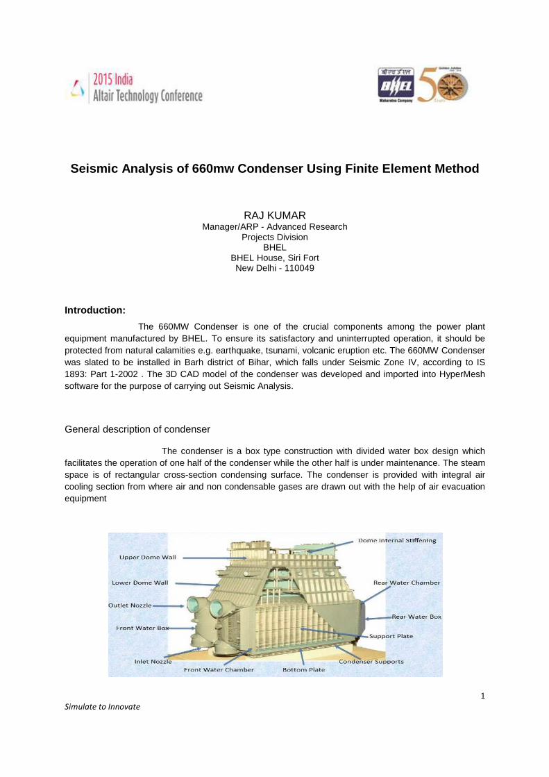
1 Simulate to Innovate Seismic Analysis of 660mw Condenser Using Finite Element Method Introduction: The 660MW Condenser is one of the crucial components among the power plant equipment manufactured by BHEL. To ensure its satisfactory and uninterrupted operation, it should be protected from natural calamities e.g. earthquake, tsunami, volcanic eruption etc. The 660MW Condenser was slated to be installed in Barh district of Bihar, which falls under Seismic Zone IV, according to IS 1893: Part 1-2002 . The 3D CAD model of the condenser was developed and imported into HyperMesh software for the purpose of carrying out Seismic Analysis. General description of condenser The condenser is a box type construction with divided water box design which facilitates the operation of one half of the condenser while the other half is under maintenance. The steam space is of rectangular cross-section condensing surface. The condenser is provided with integral air cooling section from where air and non condensable gases are drawn out with the help of air evacuation equipment RAJ KUMAR Manager/ARP - Advanced Research Projects Division BHEL BHEL House, Siri Fort New Delhi - 110049
-
Upload
vuongtuong -
Category
Documents
-
view
250 -
download
0
Transcript of OS-09-Seismic Analysis of 660mw Condenser Using Finite ... · PDF fileSeismic Analysis of...
1
Simulate to Innovate
Seismic Analysis of 660mw Condenser Using Finite Element Method
Introduction:
The 660MW Condenser is one of the crucial components among the power plant equipment manufactured by BHEL. To ensure its satisfactory and uninterrupted operation, it should be protected from natural calamities e.g. earthquake, tsunami, volcanic eruption etc. The 660MW Condenser was slated to be installed in Barh district of Bihar, which falls under Seismic Zone IV, according to IS 1893: Part 1-2002 . The 3D CAD model of the condenser was developed and imported into HyperMesh software for the purpose of carrying out Seismic Analysis.
General description of condenser
The condenser is a box type construction with divided water box design which facilitates the operation of one half of the condenser while the other half is under maintenance. The steam space is of rectangular cross-section condensing surface. The condenser is provided with integral air cooling section from where air and non condensable gases are drawn out with the help of air evacuation equipment
RAJ KUMAR Manager/ARP - Advanced Research
Projects Division BHEL
BHEL House, Siri Fort New Delhi - 110049
2
Simulate to Innovate
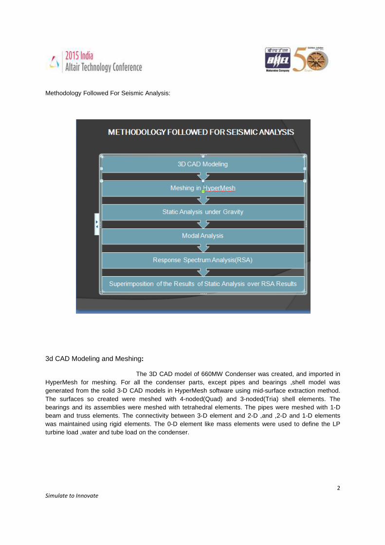
Methodology Followed For Seismic Analysis:
3d CAD Modeling and Meshing:
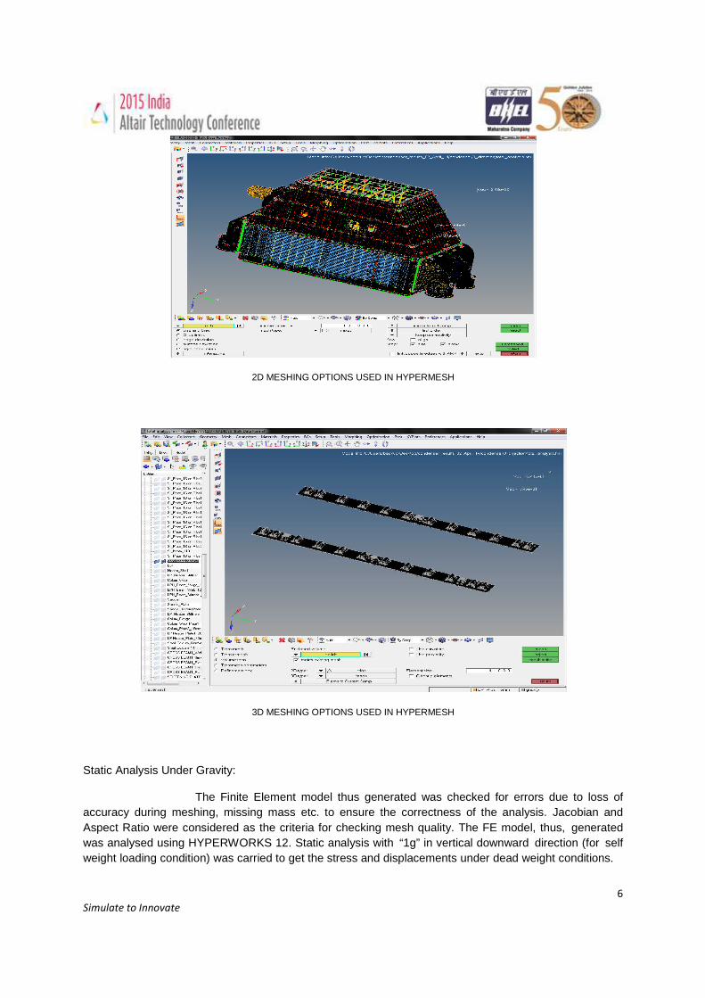
The 3D CAD model of 660MW Condenser was created, and imported in HyperMesh for meshing. For all the condenser parts, except pipes and bearings ,shell model was generated from the solid 3-D CAD models in HyperMesh software using mid-surface extraction method. The surfaces so created were meshed with 4-noded(Quad) and 3-noded(Tria) shell elements. The bearings and its assemblies were meshed with tetrahedral elements. The pipes were meshed with 1-D beam and truss elements. The connectivity between 3-D element and 2-D ,and ,2-D and 1-D elements was maintained using rigid elements. The 0-D element like mass elements were used to define the LP turbine load ,water and tube load on the condenser.
3
Simulate to Innovate
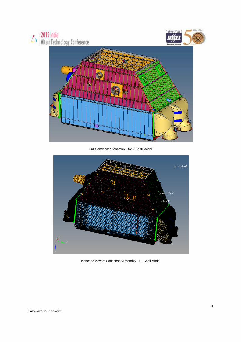
Full Condenser Assembly - CAD Shell Model
Isometric View of Condenser Assembly - FE Shell Model
4
Simulate to Innovate
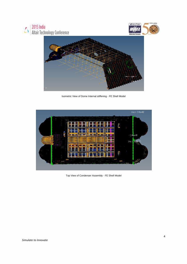
Isometric View of Dome Internal stiffening - FE Shell Model
Top View of Condenser Assembly - FE Shell Model
5
Simulate to Innovate
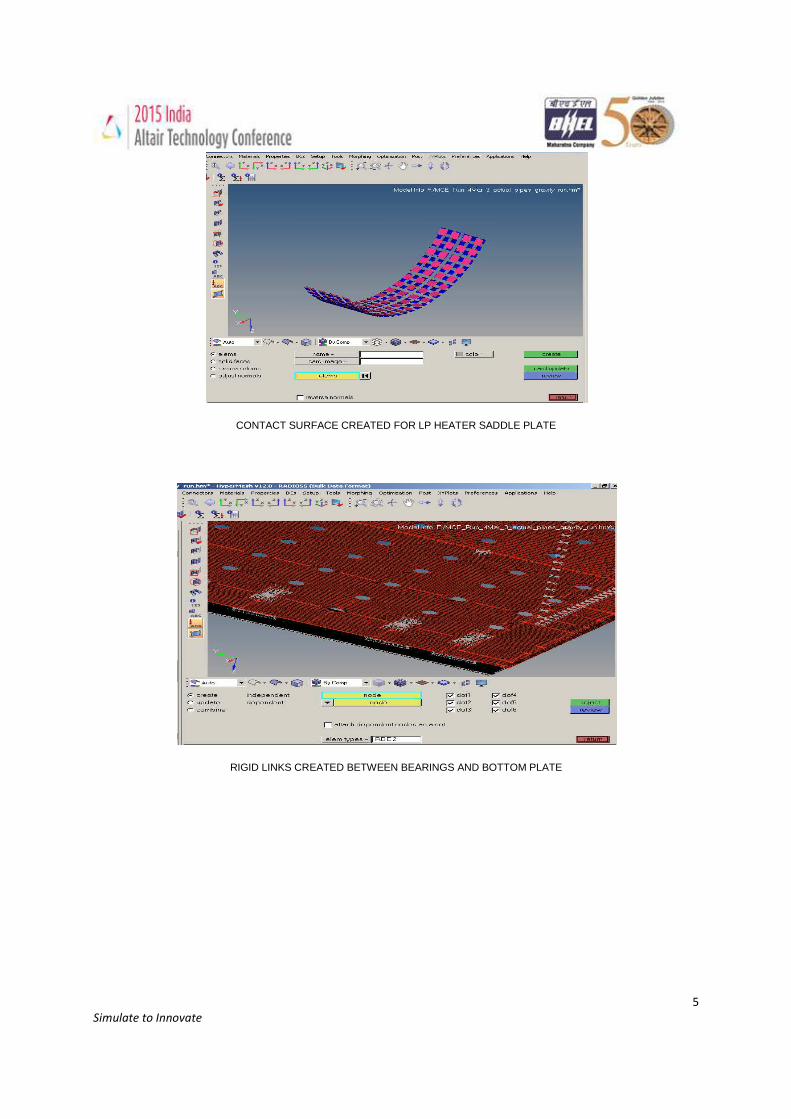
CONTACT SURFACE CREATED FOR LP HEATER SADDLE PLATE
RIGID LINKS CREATED BETWEEN BEARINGS AND BOTTOM PLATE
6
Simulate to Innovate
2D MESHING OPTIONS USED IN HYPERMESH
3D MESHING OPTIONS USED IN HYPERMESH
Static Analysis Under Gravity:
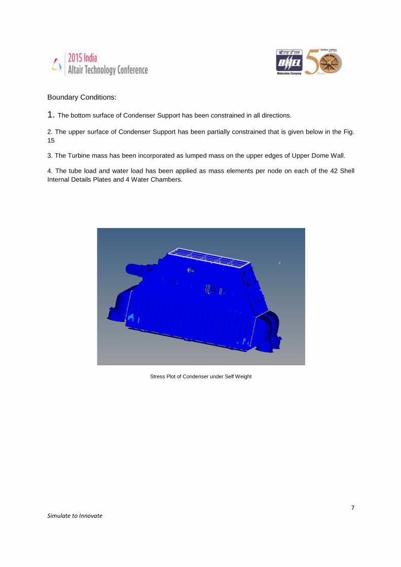
The Finite Element model thus generated was checked for errors due to loss of accuracy during meshing, missing mass etc. to ensure the correctness of the analysis. Jacobian and Aspect Ratio were considered as the criteria for checking mesh quality. The FE model, thus, generated was analysed using HYPERWORKS 12. Static analysis with “1g” in vertical downward direction (for self weight loading condition) was carried to get the stress and displacements under dead weight conditions.
7
Simulate to Innovate
Boundary Conditions:
1. The bottom surface of Condenser Support has been constrained in all directions.
2. The upper surface of Condenser Support has been partially constrained that is given below in the Fig. 15
3. The Turbine mass has been incorporated as lumped mass on the upper edges of Upper Dome Wall.
4. The tube load and water load has been applied as mass elements per node on each of the 42 Shell Internal Details Plates and 4 Water Chambers.
Stress Plot of Condenser under Self Weight
8
Simulate to Innovate
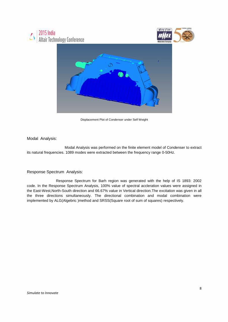
Displacement Plot of Condenser under Self Weight
Modal Analysis:
Modal Analysis was performed on the finite element model of Condenser to extract its natural frequencies. 1089 modes were extracted between the frequency range 0-50Hz.
Response Spectrum Analysis:
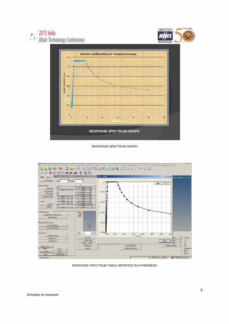
Response Spectrum for Barh region was generated with the help of IS 1893: 2002 code. In the Response Spectrum Analysis, 100% value of spectral accleration values were assigned in the East-West,North-South direction and 66.67% value in Vertical direction.The excitation was given in all the three directions simultaneously. The directional combination and modal combination were implemented by ALG(Algebric )method and SRSS(Square root of sum of squares) respectively.
9
Simulate to Innovate
RESPONSE SPECTRUM GRAPH
RESPONSE SPECTRUM TABLE IMPORTED IN HYPERMESH
10
Simulate to Innovate
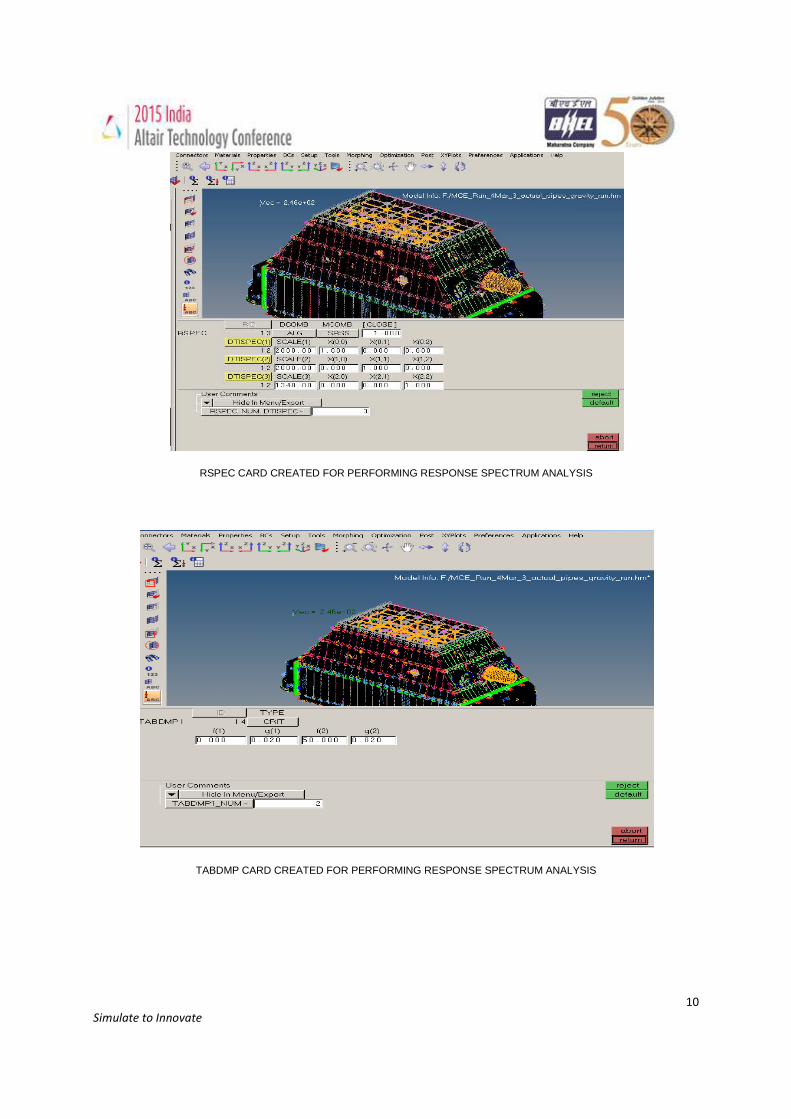
RSPEC CARD CREATED FOR PERFORMING RESPONSE SPECTRUM ANALYSIS
TABDMP CARD CREATED FOR PERFORMING RESPONSE SPECTRUM ANALYSIS
11
Simulate to Innovate
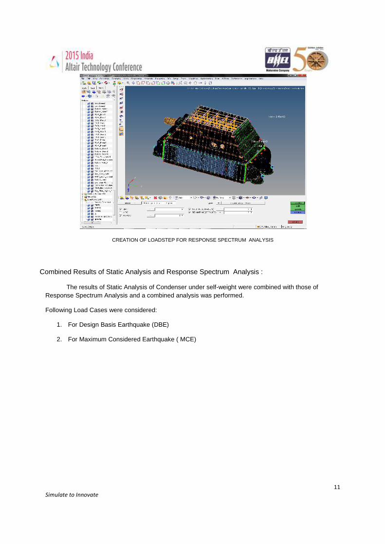
CREATION OF LOADSTEP FOR RESPONSE SPECTRUM ANALYSIS
Combined Results of Static Analysis and Response Spectrum Analysis :
The results of Static Analysis of Condenser under self-weight were combined with those of Response Spectrum Analysis and a combined analysis was performed.
Following Load Cases were considered:
1. For Design Basis Earthquake (DBE)
2. For Maximum Considered Earthquake ( MCE)
12
Simulate to Innovate
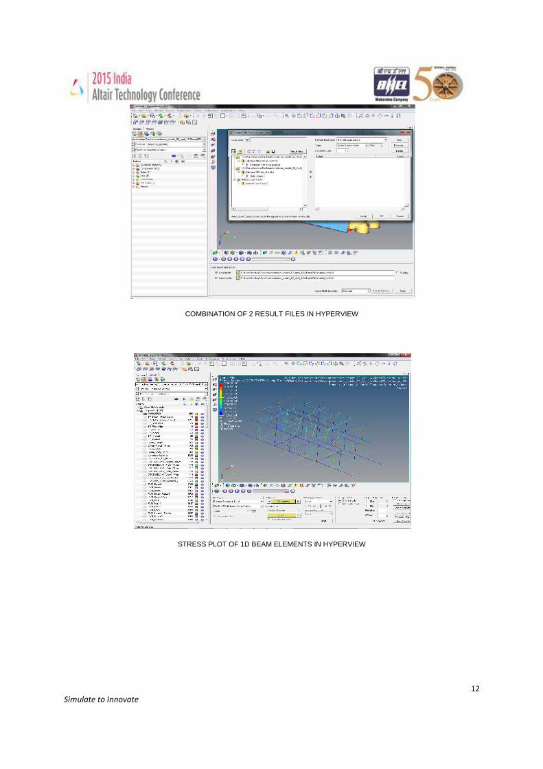
COMBINATION OF 2 RESULT FILES IN HYPERVIEW
STRESS PLOT OF 1D BEAM ELEMENTS IN HYPERVIEW
13
Simulate to Innovate
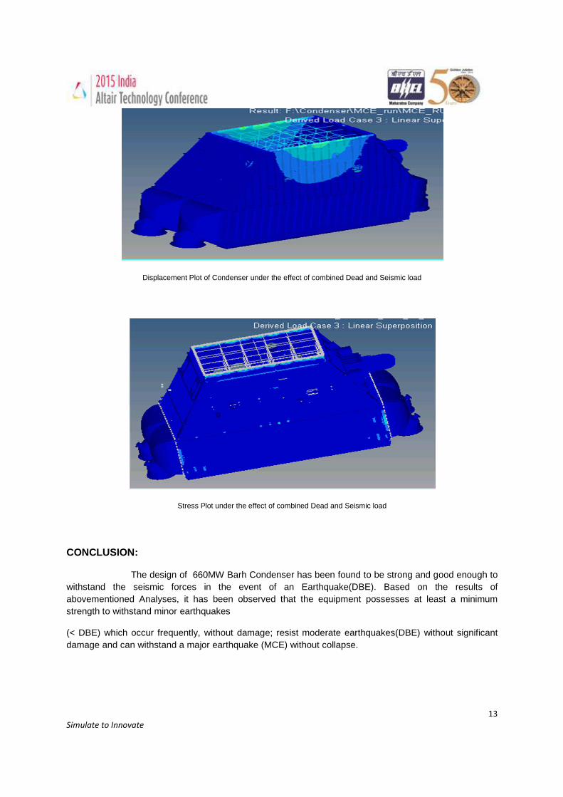
Displacement Plot of Condenser under the effect of combined Dead and Seismic load
Stress Plot under the effect of combined Dead and Seismic load
CONCLUSION:
The design of 660MW Barh Condenser has been found to be strong and good enough to withstand the seismic forces in the event of an Earthquake(DBE). Based on the results of abovementioned Analyses, it has been observed that the equipment possesses at least a minimum strength to withstand minor earthquakes
(< DBE) which occur frequently, without damage; resist moderate earthquakes(DBE) without significant damage and can withstand a major earthquake (MCE) without collapse.