Orthogonal Frequency Division Multiplexing and Related...
45
E E CE5984 CE5984 Orthogonal Frequency Division Multiplexing and Related Orthogonal Frequency Division Multiplexing and Related Technologies Technologies Fall 2007 Fall 2007 Mohamed Essam Khedr Modulation (Mapping) in OFDM
Transcript of Orthogonal Frequency Division Multiplexing and Related...
EECE5984CE5984Orthogonal Frequency Division Multiplexing and Related Orthogonal Frequency Division Multiplexing and Related
TechnologiesTechnologiesFall 2007Fall 2007
Mohamed Essam Khedr
Modulation (Mapping) in OFDM

SyllabusSyllabus• Wireless channels characteristics (7.5%) 1
• OFDM Basics (10%) 1
• Modulation and Coding (10%) 2– Linear and nonlinear modulation – Interleavin\g and channel coding – Optimal bit and power allocation – Adaptive modulation

P/SQAM
decoder
invert channel
=frequencydomain
equalizer
S/P
quadratureamplitude
modulation (QAM)
encoder
N-IFFTadd
cyclic prefix
P/SD/A +
transmit filter
N-FFT S/Premove cyclic prefix
TRANSMITTER
RECEIVER
N subchannels N complex samples
N complex samplesN subchannels
Receive filter
+A/D
multipath channel
An OFDM Modem An OFDM Modem
Bits
00110

OFDM Mathematics1
2
0
( ) k
Nj f t
kk
s t X e π−
=
= t ≡ [ 0,Τos]
Orthogonality Condition
*1 2
0
( ). ( ) 0T
g t g t dt =In our case
2 2
0
. 0p q
Tj f t j f te e dtπ π− =
For p ≠ q Where fk=k/T
os
os
os

Spectrum ShapingSpectrum Shaping
• FCC manages spectrum• Specifies power spectral
density mask– Adjacent channel interference– Roll-off requirements
• Implications to OFDM– Zero tones on edge of band– Time domain windowing
‘smoothes’ adjacent symbols
IEEE 802.11a
Inband
Adjacent channel
Reference: Std 802.11a
frequency
Zero tones
Ofdm symbol

Mitigating Mitigating MultipathMultipath effectseffects• Channel estimation required • Training based methods
– Tradeoffs in overhead, complexity, and delays
• Linear equalizers can completely eliminate ISI, but this may enhance noise.
• Decision feedback (nonlinear) equalizers can improve performance.

EqualizationEqualization• Digital Equalizer
• Criterion for coefficient choice– Minimize BER (Hard to solve for ws)– Eliminate ISI (Zero forcing, enhances noise)– Minimize MSE between dn and dn
nneq zwzwwzH −− +++= ...)( 1
10

Discrete Random Variables and ProbabilityDiscrete Random Variables and ProbabilityQuick RevisionQuick Revision
Random variable X assumes a value as a function from outcomes of a process which can not be determined in advance.
Sample space S of a random variable is the set of all possible values of thevariable X.
ΩΩΩΩ: set of all outcomes and divide it into elementary events, or states
1)(
=x
xp 0)(1 ≥≥ xp

a5
a5
1
Continuous Random VariablesContinuous Random Variables
1
)()( αα
α XX Ff∂∂=
)Pr()( αα ≤= XFX
Cummulative distribution function(CDF)
Probability density function (PDF)
1)( =∂∞
∞−
ααXf
?)(
?)(
=−∞=∞
X
X
F
F

Ensemble Average Ensemble Average
• Mean:– Continuous
– Discrete
• Variance
∞
∞−
∂== ααα )( E XfXX
( )222 XX −=σ
==k
kk XX )Pr( αα
( ) ( ) ( ) ααασ ∂−=−= ∞
∞−Xx fXXX
222 E

Correlation & CovarianceCorrelation & Covariance• Crosscorrelation • Covariance
• If <X> or <Y> equal zero, correlation equals covariance
• Note that X* means the complex conjugate of X
*XYE=XYr
( )( ) ***XY YXXYYYXX-c −=−= EE
irir jXXjXXX −=+= ** )(
1−=j

Random ProcessRandom Process
• X, Y need not be separate events• X, Y can be samples of process observed at different instants t1, t2
( ) ( ) 2*
121 E),( tZtZttRZ =
( )( ) *2211
*21 )()()(t)(E),( tZtZZtZttCZ −−=
( )1tZX =
( )2tZY =
*XY XYr E=
( )( ) *XY YYXX-c −= E
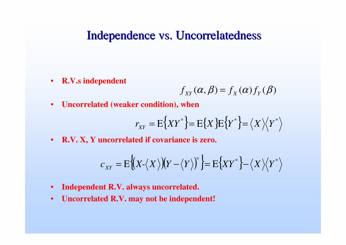
Independence vs. UncorrelatednessIndependence vs. Uncorrelatedness
• R.V.s independent
• Uncorrelated (weaker condition), when
• R.V. X, Y uncorrelated if covariance is zero.
• Independent R.V. always uncorrelated.• Uncorrelated R.V. may not be independent!
)()(),( βαβα YXXY fff =
*** EEE YXYXXYrXY ===
( )( ) *EE YXXYYYXX-c **XY −=−=

Major Channel EffectsMajor Channel Effects• Propagation Loss: attenuation, also called path loss
• Gaussian Noise and Interference: Time variant nature due to mobility of objects in an environment
• Time Dispersion: multiple reflections due to obstacles leading to multipaths
• Doppler Effects: Time variant nature due to mobility of objects in an environment
2
4
=d
GGPP
RTT
R
πλ
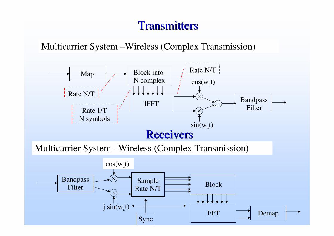
TransmittersTransmitters
Multicarrier System –Wireless (Complex Transmission)
Map Block into N complex
IFFT BandpassFilterRate 1/T
N symbols
Rate N/T
Rate N/T
cos(wct)
sin(wct)
ReceiversReceiversMulticarrier System –Wireless (Complex Transmission)
Demap
Block
FFT
BandpassFilter
cos(wct)
j sin(wct)
SampleRate N/T
Sync

Frequency Domain EqualizationFrequency Domain Equalization
• For the kth carrier:xk = Hk sk + vk
where Hk = n hk(nTs) exp(j2π k n / N) where n = 0, …,. N-1
• Frequency domain equalizer xk
Hk-1
ssk
• Noise enhancement factor
k
|Hk|2
|Hk-1|2
kgood
bad

Example: IEEE 802.11aExample: IEEE 802.11a
• IEEE 802.11 employs adaptive modulation– Code rate & modulation depends on distance from base station– Overall data rate varies from 6 Mbps to 54 Mbps
Reference: IEEE Std 802.11a-1999

Ideal Channel EstimationIdeal Channel Estimation• Wireless channels change frequently ~ 10 ms• Require frequent channel estimation• Many systems use pilot tones – known symbols
– Given sk, for k = k1, k2, k3, … solve xk = l=0L hl e-j2π k l/N sk for hl
– Find Hk = l=0L hl e-j2π k l / N (significant computation)
• More pilot tones– Better noise resilience– Lower throughput (pilots are not informative)
frequency
mag
nitu
de Pilot tones

Channel Estimation Via InterpolationChannel Estimation Via Interpolation
• More efficient approach is interpolation• Algorithm
– For each pilot ki find Hki = xki / ski
– Interpolate unknown values using interpolation filter– Hm = αm,1 Hk1 + αm,2 Hk2 + …
• Comments– Longer interpolation filter: more computation, timing sensitivity– Typical 1dB loss in performance in practical implementation
frequency
mag
nitu
de

Vector modulator & complex baseband
• Independently modulate cos(2πfCt) & sin(2πfCt) and sum.• Coherent demodulator for ‘cos’ transmission blind to ‘sin’ trans. and vice-versa.
Mult
Mult
ADD
Cos(2ππππfCt)
Sin(2ππππfCt)
bR(t)
bI(t)
• “2 channels for price of 1”
• Still single carrier
• Complex baseband:
b(t) = bI(t) + jbR(t)
• More about this later

Vector demodulator
Mult
Mult
Cos(2ππππfCt)
Sin(2ππππfCt)
bR(t)
bI(t)
Derive local carrier(cos & sin)
Lowpassfilter
Lowpassfilter
bR(t)cos(2ππππfCt)+
bI(t)sin(2ππππfCt)

Mapping bit stream to baseMapping bit stream to base--bandband
Pulse-shaping filter
..1 1 0 1 0 ... Generate impulses
t
V V
t
‘Map to base-band’
• Stream of impulses produced according to bits & approach
e.g. for unipolar: unit impulse for ‘1’ & zero for ‘0’.
• Pass impulse stream through pulse shaping filter.
• Impulses & filter may be analogue or digital (generally digital)

Techniques for digital transmission
• Can modulate amplitude, frequency &/or phase of cos(2πƒπƒπƒπƒCt).
• These 3 forms of modulation when used independently give us
(a) amplitude shift keying (ASK) (b) frequency shift keying (FSK)(c) phase shift keying (PSK).
• There are many versions of each of these.
• Possible to use a combination of more than one form.
• Consider simplest binary forms first.

Binary frequency shift keying (B-FSK)
Modulatecarrier
Map to base-band
10110
tvolts
t

Binary amplitude shift keying (B-ASK)
Map to base-band
10110
tvolts
Multiply

Binary phase shift keying (B-PSK)
Map to base-band
10110
tvolts
Multiply
t

4-ary amplitude shift keying (ASK)
Map to base-band
10110
t
volts
Multiply
tvolts
volts
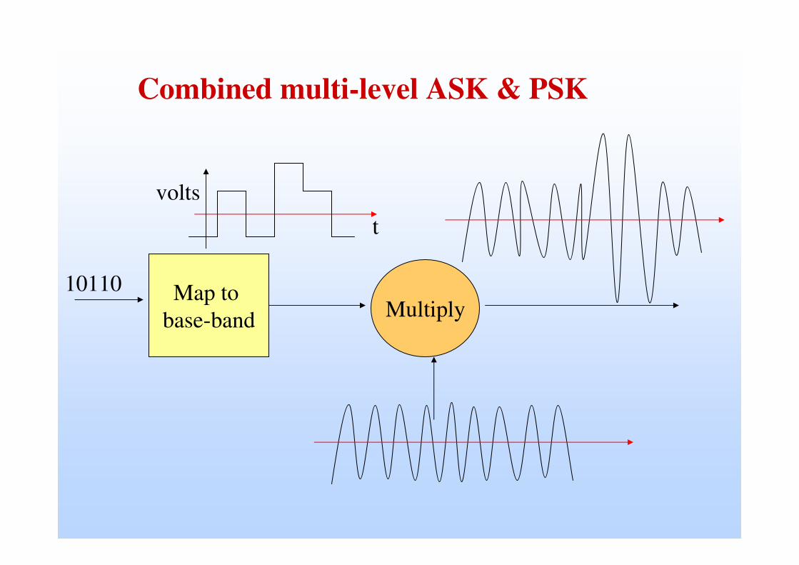
Combined multi-level ASK & PSK
Map to base-band
10110
tvolts
Multiply

Constellation diagramsShow “in phase” and “quadrature” components as a graph as illustrated below for two examples:
Binary ASK with symbols 0 & Acos(..)
In phase with carrier
Quadrature to carrier
Q
I
4-ary ASK with symbols 0, Acos(..), 2Acos(..), 3Acos(..)
0 A 2A 3A

Complex baseband & vector-modulator/demodulator
Vector modulator:
..11010.. Map
sin(2ππππfCt)
cos(2ππππfCt)
bI(t)
bR(t)
bR(t)cos(2ππππfCt)+
bI(t)sin(2ππππfCt)Map..10010..

Vector demodulator
Mult
Mult ThresholdDetector
ThresholdDetector
Cos(2ππππfCt)
Sin(2ππππfCt)
bR(t)
bI(t)Lowpass
Lowpass
..11010..
Derive localcarrier(cos & sin)
Receivedsignal r(t)
..10010..

Constellation diags for ASK with complex baseband
In phase with carrier
Quadrature to
carrier
0 A 2A 3A
Binary ASK for bR(t) & bI(t) 4-ary ASK
for bR(t) & bI(t)
In quadrature
Inphas
A
A 3A
A
0

ReReal pt
8-PSK16-PSK
Imag pt
QPSK is 4-PSK. What about 8-PSK & 16-PSK?
Can have 8-PSK (3 bits/symbol) & 16-PSK (4 bits/symbol). Constellation diagrams for shown below.
Differential forms of QPSK & M-PSK often used where changes in phase signify the data. Principle similar to DPSK .

‘Single carrier’ receiver
• Receiver must demodulate to obtain base-band b(t) .• Pulse shapes distorted & affected by noise. • Sample & detect for rectangular pulses discussed in last lecture.• May work for low bit-rates over channels with little distortion or noise• Performance can be improved by introduction of
– a matched filter optimally tuned to shape of transmitted pulses to minimize effect of noise (AWGN).
– a channel equalizer to cancel out distortion introduced by channel.
..1100..Matchedfilter
Demodulator Channelequaliser
Sample&
detectb(t)
Channelsignal + AWGN

Recall: Attenuation, Dispersion Effects: ISI!Recall: Attenuation, Dispersion Effects: ISI!
Source: Prof. Raj Jain, WUSTL
Inter-symbol interference (ISI)

Channel equaliser
• Channel equaliser’ is an ‘adaptive filter’ • Programmed to correct any differences between pulses seen at output
of matched filter & ideal RC pulses required by detector. • Aims to cancel out effect of the channel, • In particular the effects of frequency selective fading. • Received amplitude reduced at some frequencies & reinforced at
others.• Equalizer must do opposite of this. • Must adapt to changes in fading channel characteristics.• A demanding filtering task, and it cannot always be successful.• If there is a very deep fade, it will just not be possible to reverse it.• Trying to do so will just emphasize noise at frequency of deep fade.• Single carrier sine-wave modulation still widely used.

Spectra of Spectra of rectrect & & sincsinc pulsespulses
T.sinc1/T(f)
t
T/2-T/2
1
rectT(t)
f
T
1/T-1/T
2/T-2/T
3/T-3/T
4/T-4/T
Fourier transform
Real part shownImag part = 0
f
1/(2T)-1/(2T)
T
T.rect1/T(f)sincT(t)
t
1
T-T
2T-2T
3T-3T
4T-4T
Fourier transform
Real pt shownImag pt = 0

Spectra of 50% RC pulses & spectraSpectra of 50% RC pulses & spectra
RC(f)
tT/2-T/2
1
rc(t)
f
T
1/T-1/T
2/T-2/T
3/T-3/T
4/T-4/T
Fourier transform
Real part shownImag part = 0
-3T/43T/4
f
1/(2T)-1/(2T)
T
RC(f)rc(t)
t
1
T-T
2T-2T
3T-3T
4T-4T
Fourier transform
Real pt shownImag pt = 0
3/(4T)
-3/(4T)

Modulation of sub-carriers
• With IEEE802.11, each OFDM sub-carrier modulated by choice of:– binary-PSK, (1 bit per pulse)– QPSK, (2 bits per pulse)– 16-QAM (4 bits per pulse)– 64-QAM (6 bits per pulse)
• 16-QAM & 64-QAM are multi-level schemes.• Implement by vector-modulator according to ‘constellations’.• Illustrate for QPSK & 16-QAM• ‘Gray coding’ for 16-QAM makes nearest dots differ in just 1 bit.• Differential PSK, QPSK & QAM used where the difference between the current &
previous pulse specifies the bit pattern.

Constellation for QPSK
modulating cos
0,0
0,1
1,0
1,1
Bit1 Bit2 bR bI0 0 A A0 1 A -A1 0 -A A1 1 -A -A
Modulating sin
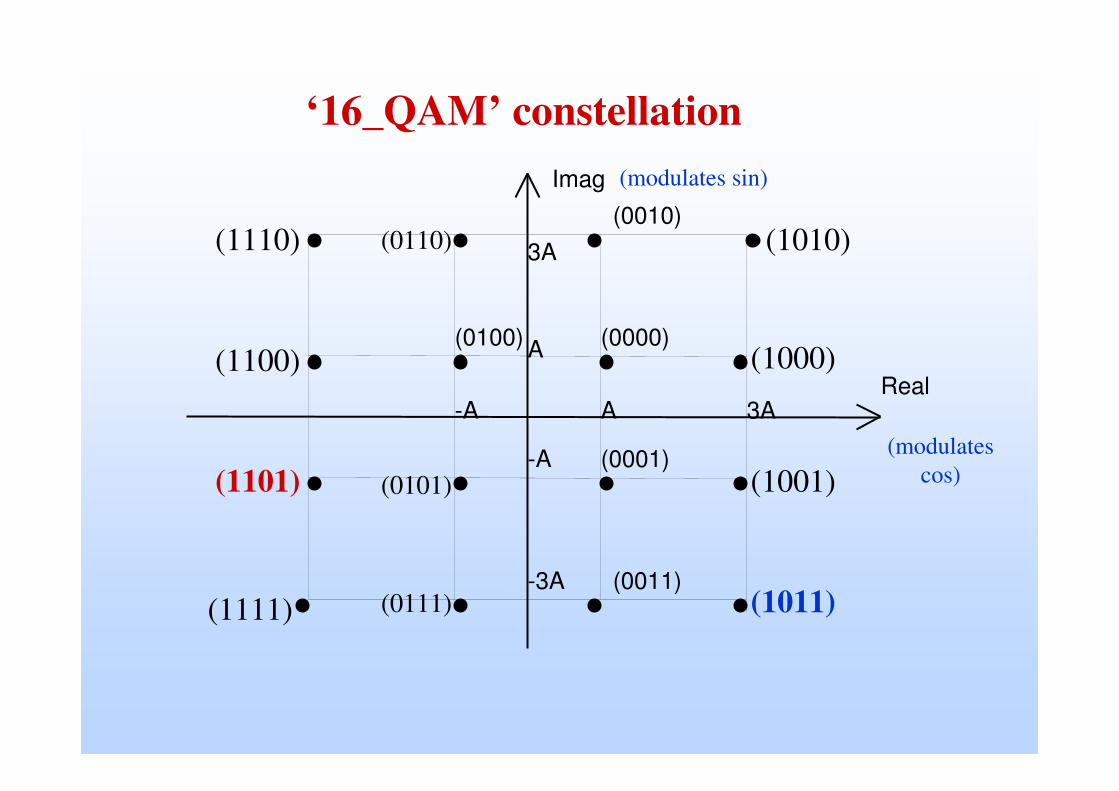
‘16_QAM’ constellation
A
3A
-A
-3A
A 3AReal
Imag
(0000)
-A
(0001)
(0010)
(0011)
(0100)(1000)
(1001)
(1010)
(1011)
(1100)
(1101)
(1110)
(1111)
(0110)
(0101)
(0111)
(modulates cos)
(modulates sin)

MulticarrierMulticarrier vsvs EqualizersEqualizers
• Equalizers use signal processing in receiver to eliminate ISI. • Linear equalizers can completely eliminate ISI (ZF), but this may enhance
noise. MMSE better tradeoff.
• Equalizer design involves tradeoffs in complexity, overhead, andperformance (ISI vs. noise).– Number of filter taps, linear versus nonlinear, complexity and overhead of training
and tracking
• Multicarrier is an alternative to equalization– Divides signal bandwidth to create flat-fading subchannels.

Introduction
-60 -40 -20 0 20 40 60-50
-40
-30
-20
-10
0
10
f [MHz]
pow
er s
pect
rum
mag
nitu
de [
dB] OFDM spectrum for N
FFT = 128, N
w in = 12, N
guard = 24, oversampling = 1
0 20 40 60 80 100 120 140 160 180 200-0.2
-0.1
0
0.1
0.2time domain signal (baseband)
sample nr.
imaginaryreal
OFDM Block DiagramOFDM Block Diagram
OFDM modulation
(IFFT)
Channel coding /
interleaving
Guard interval
I/Q I/QSymbol mapping
(modulation)
Transmitter
N symbols
OFDM demod. (FFT)
Decoding / deinter-leaving
Guard interval removal
Time sync.
I/Q I/Q
symbol de-mapping
(detection)
Channel est.
ReceiverFFT-part
time
1 OFDM symbol
Channel impulse response:
0101010010110

P/S
QAM demod
decoder
invert channel
=frequencydomain
equalizer
S/P
quadratureamplitude
modulation (QAM)
encoder
N-IFFTadd
cyclic prefix
P/SD/A +
transmit filter
N-FFT S/Premove cyclic prefix
TRANSMITTER
RECEIVER
N subchannels 2N real samples
2N real samplesN subchannels
Receive filter
+A/D
multipath channel
Summary: An OFDM Modem Summary: An OFDM Modem
Bits
00110