ORNL/NRC/LTR-08/02, Survey of I&C Technologies and Their ...
42
ORNL/NRC/LTR-08/02 Survey of I&C Technologies and their Application in Nuclear Power Plants December 2007 Prepared by Kofi Korsah and Michael Muhlheim NRC Technical Monitor: Tekia Govan ORNL Manager: Kofi Korsah
Transcript of ORNL/NRC/LTR-08/02, Survey of I&C Technologies and Their ...

ORNL/NRC/LTR-08/02
Survey of I&C Technologies and their Application in Nuclear Power Plants December 2007 Prepared by Kofi Korsah and Michael Muhlheim NRC Technical Monitor: Tekia Govan ORNL Manager: Kofi Korsah


This report was prepared as an account of work sponsored by an agency of the United States Government. Neither the United States Government nor any agency thereof, nor any of their employees, makes any warranty, express or implied, or assumes any legal liability or responsibility for the accuracy, completeness, or usefulness of any information, apparatus, product, or process disclosed, or represents that its use would not infringe privately owned rights. Reference herein to any specific commercial product, process, or service by trade name, trademark, manufacturer, or otherwise, does not necessarily constitute or imply its endorsement, recommendation, or favoring by the United States Government or any agency thereof. The views and opinions of authors expressed herein do not necessarily state or reflect those of the United States Government or any agency thereof.

ORNL/NRC/LTR-08/02
Engineering Science and Technology Division
SURVEY OF I&C TECHNOLOGIES AND THEIR APPLICATION IN NUCLEAR POWER PLANTS
Kofi Korsah and Michael Muhlheim
Contributors to the NUREG/CR on which this letter report is based: J.A. Mullens, A. Loebl, M. Bobrek, M.K. Howlader,
S.M. Killough, M.R. Moore, P.D. Ewing, M. Sharpe, and A. Shourbaji.
NRC Technical Monitor: Tekia Govan ORNL Project Manager: Kofi Korsah
December 2007
Prepared for U.S. Nuclear Regulatory Commission
under DOE Interagency Agreement 1886-N640-9W
NRC JCN No. Y6962
Prepared by the OAK RIDGE NATIONAL LABORATORY
P.O. Box 2008 Oak Ridge, Tennessee 38731-6285
managed by UT-Battelle, LLC for the
U.S. DEPARTMENT OF ENERGY under contract DE-AC05-00OR22725


CONTENTS
Page LIST OF FIGURES................................................................................................................................ v ABSTRACT .........................................................................................................................................vii1. INTRODUCTION............................................................................................................................. 1 2. SUMMARY FINDINGS FROM TECHNOLOGY FOCUS AREAS .............................................. 2
2.1 Sensors and Measurement Systems ....................................................................................... 2 2.1.1 Regulatory Impact of Sensors and Measurement System Technologies .................. 3
2.2 Communication Media and Networking ................................................................................ 3 2.2.1 Regulatory Impact of Communications and Networking ......................................... 4
2.3 Microprocessors and other Integrated Circuits ...................................................................... 5 2.3.1 Regulatory Impact Arising from Integrated Circuit Miniaturization ........................ 5 2.3.2 Sensitivity to Environmental Conditions .................................................................. 7
2.4 Computational Platforms ....................................................................................................... 7 2.4.1 Regulatory Impact of Advances in Computational Platforms .................................. 8
2.5 Surveillance, Diagnostics, and Prognostics............................................................................ 9 2.5.1 Regulatory Impact of Advances in Surveillance, Diagnostics, and
Prognostics .............................................................................................................. 11 2.6 High Integrity Software........................................................................................................ 11
2.6.1 Regulatory Impact of High Integrity Software ....................................................... 14 2.7 I&C Architectures for New Plants ....................................................................................... 15
2.7.1 System-Level I&C Architecture for the EPR.......................................................... 16 2.7.2 Digital I&C Issues and How They are Addressed in the EPR ................................ 192.7.3 Regulatory Impact of Fully Digital I&C Architectures in NPPs............................. 20
3. DOWNSELECTED FOCUS AREAS............................................................................................. 23 3.1 Rationale for Downselection................................................................................................ 23 3.2 Screened Technologies Based on the Review...................................................................... 23 3.3 Implications of Current Trends in I&C Architectures for NPPs .......................................... 24
REFERENCES..................................................................................................................................... 27
iii


LIST OF FIGURES
Figure Page
1 A simple model of an ARINC 653 partitioned system.................................................... 8 2 EPR I&C architecture.................................................................................................... 17 3 Block diagram of the EPR PAC module ....................................................................... 17 4 The MSI forms a logical boundary between the rest of the safety system and the
nonsafety interfaces ....................................................................................................... 20
v


EXECUTIVE SUMMARY
This letter report presents findings from Task 2 of the Emerging Technologies project. The primary objective of the Emerging Technologies project is to assist the U. S. Nuclear Regulatory Commission (NRC) in the identification of key research areas on emerging technologies within the instrumentation and controls (I&C) field that may become important in the future. The Emerging Technologies study will provide “intelligence” pertaining to new/improved/advanced I&C equipment and systems that are being studied or developed by the vendors for use in reactor plant designs. This will enable informed regulatory judgments to be made regarding their usage. The output of the study is provided as a series of NUREG/CRs published about every 2-3 years. The third NUREG/CR in the series will be submitted to the NRC in January 2008. The objective of Task 2 of the Emerging Technologies project is to identify the most relevant emerging technologies that are likely to be employed in future safety-related applications. It focuses on specific technologies screened from the products identified within the technology areas addressed in Task 1 of the Emerging Technologies project. The screening is based on (1) the likelihood that the technology will be used in the nuclear industry, (2) the amount of available information on the technology that could support regulatory decision making, and (3) regulatory impact of the technology. To meet the objective of this task, seven technology focus areas were reviewed: (1) Sensors and Measurement Systems, (2) Communications Media and Networking, (3) Microprocessors and Other Integrated Circuits (ICs), (4) Computational Platforms, (5) Diagnostics and Prognostics, (6) High-Integrity Software, and (7) I&C Architectures in New Plants. For the latter, we reviewed the instrumentation and control (I&C) features for several new reactor designs [e.g., APWR by Mitsubishi Heavy Industries and U.S. Evolutionary Pressurized Reactor (EPR) by AREVA NP]. The review indicates that these designs employ fully digital and networked architectures, with analog trip backup in some cases. Some safety-related subsystems are implemented using Application Specific Integrated Circuits (ASICs) or Field Programmable Gate Arrays (FPGAs). One issue is how much verification and validation (V&V) should be required (i.e., must V&V be required to the same level as a computer-based system?). Based on the review, we consider that continued advances in the following technology focus areas need to be followed closely because these are likely to have the most regulatory impact with regard to nuclear power plant safety I&C systems. 1. Microprocessors and Other ICs Growing system complexity of semiconductor devices will make it quite difficult to guarantee delivering future products free of errors. The successful development of high-k transistor ICs and the potential for Multigate transistor ICs will revolutionize IC manufacturing procedures. This could also introduce new aging phenomena, higher sensitivity to environmental conditions (temperature and radiation), and other issues related to qualification methodologies. The use of “complex” devices such as FPGAs in safety systems need to be carefully reviewed, because such devices have the potential to be reconfigured, and reconfigurability increases reuse and the potential for adversely affecting a safety function. Use of FPGAs in safety systems also brings to focus the issue of how much V&V should be required.
vii

2. Communication and Networking I&C architectures in new plants will make extensive use of digital communication, both between safety systems and between nonsafety and safety-related systems. One of the more significant regulatory implications is maintaining not only physical and electrical independence, but also data independence between safety and nonsafety systems, thereby guaranteeing that a transmission error in one channel or division will not cause the failure of another channel or division. The independence issue is not so easily resolved with regard to wireless communications systems in nuclear power plants. Howlader et al. have developed the technical basis for regulatory guidance on implementing wireless communications in nuclear power plants. Wireless systems are likely to be limited in the foreseeable future to nonsafety-related diagnostics and maintenance systems, inventory management systems, and voice and data communications to employees and field crews. 3. High Integrity Software Although advances in software engineering have not kept pace with hardware, continuing evolutions and new methodologies in high integrity software should continue to be tracked because they have the potential to reduce the probability of common cause failures (CCFs) in digital systems. The present regulatory position is that software cannot typically be proven to be error-free and is therefore considered susceptible to CCFs if identical copies of the software are present in redundant channels of safety-related systems. The current mitigating strategies to cope with CCFs are to apply various diversity measures, along with a defense-in-depth philosophy. These measures, along with a highly reliable software development strategy, can reduce the probability of CCF to an insignificant level. 4. Sensors and Measurement System Technologies The key regulatory issues associated with sensors and measurement systems in nuclear power plants include response time requirements, accuracy and reduced uncertainties to take credit for reduced operating margins, and how much credit can be taken for increasing calibration intervals due to online sensor diagnostics or inherent lack of drift (e.g., Johnson noise thermometry). Although the emerging sensing and measurement technologies for use in the nuclear power industry represent adaptations of well-established measurement concepts, advances should continue to be tracked since they have a significant regulatory impact as enumerated above. 5. Implications of Current Trends in I&C Architectures for NPPs I&C architectures for new plants are characterized by extensive use of digital communication, networks, and multiplexing. The most significant regulatory implications include (1) the potential for CCF due to identical (software) functions in modules in redundant channels or divisions, (2) functional and data independence between safety and nonsafety systems, or between safety divisions, (3) cyber security issues, and (4) diversity and defense-in-depth issues.
viii

1. INTRODUCTION
The Nuclear Regulatory Commission (NRC) Digital System Research Plan forms the framework for guiding research that the NRC performs to update the tools used in assessing the safety of digital Instrumentation and Controls (I&C) applications in U.S. nuclear power plants. The plan for FY 2001–FY 20041 identified Emerging Technologies as an area of research. This includes topics that have been shown to be likely to be applied in the future and areas that have the potential to raise safety issues but have not been addressed. By becoming informed of emerging I&C technology and applications, the NRC “…is better prepared to make future regulatory decisions in these areas.” Oak Ridge National Laboratory (ORNL) has been tasked to perform the Emerging Technologies study. Findings are documented in NUREG/CR reports about every 2 years. The first report in the series was published March 2003 as NUREG/CR-6812, and the second was published in January 2006 as NUREG/CR-6888. Compilation of the third NUREG/CR (to be submitted to the NRC in January 2008) generally followed the pattern established in the two previous NUREG/CRs of reviewing advances in several Technology Focus Areas. However, based on the results of the Program Review in FY 2006, in which the focus of the study was redirected to include digital I&C in new plants, the focus areas were slightly modified to include I&C Architectures in New Plants. Thus, the focus areas used for this third NUREG/CR in the series are the following: 1. Sensors and Measurement Systems, 2. Communications Media and Networking, 3. Microprocessors and Other Integrated Circuits, 4. Computational Platforms, 5. Diagnostics and Prognostics, 6. High-Integrity Software, and 7. I&C Architectures in New Plants. The objective of including the I&C Architectures in New Plants focus area is to identify advances in the other technology focus areas that have been incorporated in the new plants, and their potential regulatory impacts. The purpose of Task 2 of the Emerging Technologies project is to screen these Technology Focus Areas for the most relevant emerging technologies that are likely to be employed in future safety-related applications. It focuses on specific technologies screened from the products identified within the technology areas addressed above. The screening is based on (1) the likelihood that the technology will be used in the nuclear industry and (2) the amount of available information on the technology that could support regulatory decision making. This letter report presents findings from Task 2 of the Emerging Technologies project.
1

2. SUMMARY FINDINGS FROM TECHNOLOGY FOCUS AREAS
2.1 Sensors and Measurement Systems The measurement systems, comprised of the sensing element, transducer, and signal-conditioning electronics, in currently operating nuclear power plants have not changed appreciably since their original design and are primarily based on conventional instruments and methods. The principal variables measured for safety-related applications continue to be neutron flux, temperature, pressure, radiation, flow, position, and level. The Nuclear Power Reactor Instrumentation Systems Handbook,2 published in 1973 by the U.S. Atomic Energy Commission, still provides a good general, albeit a bit dated, synopsis of the sensing systems employed in currently operating nuclear power plants. The sensing technologies that appear to be emerging in the nuclear power industry represent adaptations of well-established measurement concepts to the specific requirements of nuclear power plant environments as opposed to sui generis concepts recently conceived of specifically for the nuclear industry. As such, their characteristics, advantages, disadvantages, and deployment requirements can be reasonably extrapolated from previous deployments in industrial environments. Distributed fiber-optic-based Bragg grating thermometry appears to be well suited for monitoring the health of the major electromechanical components in the nuclear energy production process. Devices such as motors, pumps, compressors, turbines, and generators all have temperature performance characteristics indicative of their operational condition and often have sufficiently high electromagnetic fields to make electrically conductive temperature measurements disadvantageous to employ. Fiber-optic-based Bragg grating thermometry could also be deployed along pressure tap lines where it would indicate blockage or bubble formation due to the difference in heat transfer. Fiber-optic-based Bragg grating thermometry also has been demonstrated to survive long term in aggressive (noncore) radiation environments (and for several minutes within core) allowing for temperature distribution mapping within containment even in a post-severe accident radiation environment. Ultrasonic technologies appear to be near the stage where they may become more widely deployed in-vessel. Ultrasonic wireline technologies have now been deployed for almost 40 years in radiation and thermal environments as aggressive as molten corium and nuclear thermal rockets. In the late 1970s and early 1980s Babcock and Wilcox experimented with using the technology as a critical in-core heat flux monitor.3 Ultrasonic wireline thermometry’s prior limitations for deployment in nuclear power plants have been the difficulty of transmitting their small pressure wave signals through the pressure vessel wall and the relative complexity of the signal content. Higher temperature ultrasonic transducers appear to be coming of age allowing for signal conversion within the pressure boundary, and complex signal processing has become readily available with the advent of modern digital electronics. As an ab initio temperature measurement, Johnson noise thermometry (JNT) remains a technology of significant potential value to the nuclear power industry. Essentially, by providing a temperature measurement based on fundamental, nondrifting physics thermometry, recalibration intervals could be significantly increased. Moreover, a core power density could potentially be increased because of a new capability to directly and with high accuracy measure in-core temperature distributions. While little technical progress has recently been made in developing industrial quality JNT instruments, the technology remains at a development level where only a few years of concerted effort would be necessary to develop a widely deployable technology for the nuclear power industry.
2
Gamma thermometers are now coming into wide use as the long-term baseline power measurement technology in boiling-water reactor (BWR) cores, replacing traveling miniature fission chambers. Gamma thermometers have also been used for local power monitoring in commercial pressurized-water reactors (PWRs) since the early 1980s. While the technology is roughly 40 years old and is in the Instrumentation Design Basis for the Economic Simplified Boiling Water Reactor (ESBWR), gamma thermometers remain an emerging technology not yet having achieved widespread, long term deployment. Type-N thermocouples were developed in the late 1970s through 1980s as a more stable replacement for the widely deployed Type-K. The new generation of nuclear power plants now under consideration appears more likely to adopt the more stable thermocouple type because they do not have existing instrumentation amplifiers that would need to be replaced to take advantage of the increased stability. 2.1.1 Regulatory Impact of Sensors and Measurement System Technologies The key regulatory issues associated with sensors and measurement systems in nuclear power plants include response time requirements, accuracy and reduced uncertainties to take credit for reduced operating margins, and how much credit can be taken for increasing calibration intervals due to online sensor diagnostics or inherent lack of drift (e.g., Johnson noise thermometry). Emerging sensing technologies represent adaptations of well-established measurement concepts to the specific requirements of nuclear power plant environments as opposed to nuclear-industry-specific concepts. As such, present day regulatory positions with regard to their use in the nuclear power plants are not likely to require any significant modification. 2.2 Communication Media and Networking This section presents an overview of digital communication technologies and their application to field instrumentation such as sensors, controllers, and actuators. These technologies are widely used in industry in wired as well as in wireless platforms. They are beginning to find acceptance in nuclear power plants as evidenced by its plant-wide application in Gen III+ power plant designs.* Advances in digital communication systems in general have focused on boosting data transmission speeds, development of more robust protocols, error correction and encryption techniques, and (for wireless systems) spread spectrum (SS) techniques (Direct Sequence, Frequency Hopping, Time Hopped, Chirp). SS radio communications techniques have been long favored by the military because the signals are hard to jam and are difficult for an enemy to intercept. SS techniques are also gaining in popularity in industrial and commercial applications due to their advantages in transmitting data using three license-free bands known as the Industrial, Scientific, and Medical (ISM) bands (902–928 MHz with 26-MHz bandwidth, 2.4–2.4835 GHz with 83.5-MHz bandwidth, and 5.725–5.85 GHz with 125-MHz bandwidth). This is in addition to their ability to transmit data more securely because of the inherent encryption feature. Unlike narrowband signals, the various forms of the SS concept utilize a specialized digital code to spread the signal at the transmitter over a frequency band that is wider than the minimum bandwidth required to transmit the data. Other advantages of the SS signals are increasing resistance to natural interference and jamming (interfering with narrowband signals). In general, use of digital communication systems in nuclear power plants lag considerably behind nonnuclear systems due to the stringent requirements these systems have to comply with to be
*Generation of future power plants expected to incorporate digital I&C systems. By contrast, the majority of existing plants in the United States are Gen II plants.
3

acceptable for nuclear power plants applications. Gen III and III+ plants are expected to bridge this gap with their extensive application of digital I&C. One of the common industrial, wire-based, networks is the Fieldbus. A Fieldbus is a real-time distributed-digital control network with bidirectional communications, multidrop, and serial bus architecture used to link different field devices, such as controllers, transducers, actuators, and sensors. In this networking configuration, each field device requires a single wire to connect to the network cable. Fieldbus technology has matured, and several variants are available. However, despite its several advantages including lower installation and operation cost, interoperability, fewer penetrations through plant containment, improved information accuracy, etc., the use of the technology is still much more prevalent in the nonnuclear environment than in the nuclear environment. Two concerns for using Fieldbus technology in the nuclear industry are (1) the potential for common cause failures resulting from design errors and (2) the ability of the Fieldbus to guarantee deterministic responses. The IEC 61784 standards (IEC 61784-1, IEC 61784-3) address extensions to the Fieldbus technologies described in IEC 61158 in a way compatible with IEC 61508. These extensions are a standardized means of supporting real-time, safety-related, and security-related applications. IEC 61784 lists specifications for seven Fieldbus technologies. Gen III and III+ nuclear power plants currently undergoing certification [e.g., the European Pressurized Reactor (EPR)] will employ field bus technology, such as PROFIBUS DP, to communicate between safety and nonsafety systems. The PROFIBUS DP has some attractive features with regard to nuclear power plant application. These include (1) a master/slave messaging model that results in a deterministic communication protocol and (2) its suitability for use in redundant architectures. Application of wireless communications in nuclear power generating facilities remain limited to nonsafety related communication, diagnostics, inventory/database applications, and wireless local area network (LAN) devices for office use. Several trends in wireless communications have the potential to enhance the communication systems performance in nuclear power plants, but they could also present security and possible safety challenges. In any wireless application, the main concerns to be considered are the security, reliability, and spectrum management. A review is underway of established and emerging wireless technologies, including four networking topologies [personal area network (PAN), LAN, metropolitan area network (MAN), and wide area network (WAN)]. This review will be documented in the Emerging Technologies NUREG/CR report. 2.2.1 Regulatory Impact of Communications and Networking With regard to digital communication (whether wired or wireless), the overriding regulatory issue is maintaining not only physical and electrical independence, but also data independence between safety and nonsafety systems. 10 CFR 50.55a(h), “Protection and Safety Systems,” requires compliance with IEEE Standard 603-1991, “IEEE Standard Criteria for Safety Systems for Nuclear Power Generating Stations.” Clause 5.6 of IEEE Standard 603-1991 requires redundant safety systems to be independent of one another. IEEE 7-4.3.2-2003 addresses communication independence. In general, however, current industry guidance documents such as IEEE Standard 603 and IEEE 7-4.3.2 do not sufficiently define a level of detail for evaluating interdivisional communications independence. Indeed some provisions of IEEE Standard 7-4.3.2 have been found not to be suitable for endorsement by the NRC. In addition, IEEE 7-4.3.2 is currently undergoing revision and the final version may or may not be found to be suitable for endorsement and may or may not be consistent with current NRC positions.4 Therefore there is the need to establish acceptance and review criteria for safety systems communications that can be uniformly applied to a variety of digital safety system designs. To address these concerns, the NRC issued the Interim Staff Guidance DI&C-ISG-04, “Highly-Integrated Control Rooms—Communications Issues (HICRc),” in September 2007. In addition, Kisner et al. have documented in a NUREG/CR5 the technical basis for guidance that specifically
4

addresses issues related to communication among safety divisions and between safety-related equipment and equipment that is not safety related. The report examines (1) accepted networking consensus practices adopted by various standards organizations in the United States and internationally, (2) operating experience of international power reactors utilizing digital network communications in safety systems, and (3) failure mechanisms arising from several possible network architectures and message types. This NUREG/CR uses this study as a basis to develop a structured approach to provide review guidance for the evaluation of safety-to-safety and nonsafety-to-safety communications systems. Based on the technical basis/acceptance criteria provided in the NUREG/CR, Korsah et al.6 provide review procedures to guide the licensing of safety-critical display and control system design development activities and products in accordance with the requirements of 10 CFR 50.55a(h), associated standards, and regulatory requirements. The independence issue with regard to wireless communications systems in nuclear power plants is not so easily resolved. Howlader et al.7 have developed the technical basis for regulatory guidance on implementing wireless communications in nuclear power plants. Wireless systems are likely to be limited in the foreseeable future to nonsafety-related diagnostics and maintenance systems such as the ones already discussed, inventory management systems, and voice and data communications to employees and field crews. 2.3 Microprocessors and other Integrated Circuits The evolution of semiconductor devices has moved from the single transistor (discrete design) to integrated circuit (IC) with various complexities, to powerful microprocessors with various capabilities, to more advanced integrated circuits designed for specific applications [Application Specific Integrated Circuits—(ASICs)]. The direction of research and development in the semiconductor industry is exemplified by the development by Intel in early 2007, following years in research, of a prototype microprocessor called Penryn with two versions: dual-core microprocessor with 410 million transistors and quad-core with 820 million transistors. These were developed with 45-nm CMOS technology using high-k plus metal gate materials. In addition, Intel is in the process of launching an R&D program to develop 32-nm technology for future chips. The successful development of the high-k (replacing the SiO2 insulation, which was used up to the 65-nm generation presently used by many semiconductor manufacturers), in conjunction with the metal gate (replacing the silicon gate electrode used up to the 65-nm generation) made it possible to shrink the insulation layer between the gate electrode and the transistor channel in size but yet provide enough isolation needed to prevent current leakage in the off-state while at the same time allow high conduction current in the on-state. Growing system complexity of semiconductor devices will make it quite difficult to guarantee delivering future products free of errors. It is therefore essential to be able to correct errors after fabrication. In addition, reconfigurability increases reuse, since existing devices can be reprogrammed to fulfill new tasks, such as field programmable gate array devices (FPGA) and field programmable analog arrays devices (FPAA). Current research on micro-electromechanical systems devices (MEMS) to improve system reliability is geared toward the development of devices with enough intelligence to reconfigure circuitry when damage occurs, as a self-healing measure. 2.3.1 Regulatory Impact Arising from Integrated Circuit Miniaturization Reliability is one of the most important and challenging issues facing ICs in any application. There are two basic failure modes for ICs:
5

• functional failures—hard failures that cause permanent failure of the electronic circuit(s) such that the IC cannot perform the intended function,
• parametric failures—soft failures where the IC is still capable of performing the intended function but not under all specified conditions; soft failures have no lasting damage but would result in corruption of stored data.
The solid-state electronics industry is characterized by relentless pressure to expand and improve functionality and reduce costs, design and development time. As a result, device feature sizes have shrunk to the nanometer range as already discussed and design life cycles of most commercial products are less than 5 years. This introduces new reliability concerns with regard to their application in NPP environments. These concerns include the following:
• new aging phenomena, • higher sensitivity to environmental conditions (temperature, radiation), • other issues related to quality or circuit design, • increase in maintenance costs, • issues with qualification of new logical systems due to the higher component complexity. New Aging Phenomena Some of the aging issues may arise from the following concerns:
• Soft-breakdown and proton migration in the thinnest gate oxides that should appear below 3 nm. Several manufacturers are likely to follow Intel’s lead in replacing silicon oxides by other materials with a higher dielectric constant. The introduction of new materials to existing technologies, however, will most likely result in new and unprecedented electrical characterization challenges. Consequently, different test methodologies will need to be identified. The degradation mechanisms and models will also be different from the conventional ones used for silicon-based devices.8 Because the materials and the technologies needed in producing a new generation of devices are still in their early development phase, data on the aging behavior of these dielectrics are not readily available and will not be for sometime to come. Therefore, to use high-k gate insulators to resolve transistor tunneling effects problem will certainly require new time-dependent dielectric breakdown (TDD)B characterization.9
• Use of copper (Cu) interconnecting wires and low dielectric constant materials, instead of
aluminum and silicon oxide, may lead to new aging effects such as (1) polluting of the silicon by copper through diffusion in spite of the barrier between them , (2) creation of holes between the copper and the barrier, (3) potential increase of electromigration in copper wires due to defects in the interfaces,* and (4) short circuits between copper wires due to electrochemical migration. It is obvious in spite of the technological advancements and the continued research in the semiconductor industry, there are certain issues yet to be fully addressed such as the reliability of “low k” dielectrics and aging risk due to adhesion to the barrier layer. In summary, the present level of understanding of electromigration in copper/low-k structures and lead-free solder applications is insufficient.10
• The lifetime of highly integrated packages such as Ball Grid Arrays, where connections to the
printed circuits are made using solder balls under the component, is another concern. With this soldering technique, the high thermal dissipation in the complex circuits induces high-
*Electromigration remains one of the most important reliability issues in semiconductor technology. The change from Al to Cu for the metal gate electrodes has only delayed, not eliminated the threat.
6

temperature variation and acceleration of the aging of the solder balls. As a result, the lifetime may be reduced
2.3.2 Sensitivity to Environmental Conditions Most likely, there will be a higher sensitivity to environmental conditions which typically exist in NPPs that might lead to soft failures. The increase in sensitivity of electronic components to temperature and electrical overstresses (EOSs) may also become an issue. The likelihood of the following phenomena will probably increase as technology advances, which may present a new set of challenges to semiconductor manufacturers as well as users:
• There is a relationship between the time for the oxide to breakdown and rise in temperature. The rise in temperature tends to accelerate the breakdown of the oxide. Furthermore, thickness of the gate oxide is another factor in accelerating the breakdown process where thinner gate oxide causes the oxide to break down more quickly than normal. Therefore, temperature control measures inside and outside the electronic cabinets will be critical for future I&C systems.
• An increasing sensitivity to rapid and low level electrical stresses due to EOS on the systems or to electrostatic discharges (ESD). These stresses may create latent defects on the silicon die, which may decrease the remaining lifetime of the components.
• Higher sensitivity to radiation can create parasitic currents in the silicon, since highly miniaturized transistors may switch with lower transient current densities. Such interaction between radiation and silicon may lead to false transient signals in the components (Single Event Upset) or to destruction of the components. To date, SEU were only seen in aerospace applications or aviation electronics in airplanes. However, whereas a 90-nm technology SER benchmark had a best-in-class FIT* rate of 195 FITs, a 65-nm technology SER had FIT rates up to 6500 per megabit, scaled to New York City (NYC).11
• Negative bias temperature instability (NBTI) can occur during burn in and during circuit operation at elevated temperatures.12
2.4 Computational Platforms One hardware development that should have an effect on real-time operating systems is processor support for virtual machines (VMs) that essentially partitions a physical computer into several virtual computers. Because this is done in hardware, the virtual computers can even be running different operating systems. (A supervisory kernel is needed to arbitrate access to shared resources such as disk drives.) The benefit is the ability to establish a separate partition for each of a computer’s running applications and enforce this separation at the hardware level. Partitioning has been an issue for aerospace systems where weight and space constraints create the desire to put multiple applications on the same computer.13 Partitioning might be used to enhance safety by
• running a safety application and a supervisory application that checks for failure of the safety application on the same platform; and
• running multiple, diverse safety applications on the same platform to avoid CCFs due to software flaws (in implementation or functionality).
ARINC Specification 653, “Avionics Application Standard Software Interface,” is a standard for space and time partitioning in a type of system named “Integrated Modular Avionics” (IMA). ARINC 653 specifies how a computer system can be divided into partitions, each partition having its own memory and processor time allocations (Figure 1). * The Failures In Time (FIT) rate of a device is the number of failures that can be expected in one billion (109) hours of operation. This term is used particularly by the semiconductor industry.
7

Partition 1 Partition 2 Partition 3 Partition N
VIRTUALIZING OPERATING SYSTEM Interpartition Messaging, Processor Scheduling, Memory Management, etc.
HARDWARE Media, Communications, Clock, Interrupts, Memory
Management Unit, Processor, etc.
Figure 1. A simple model of an ARINC 653 partitioned system. Each partition runs one or more applications. The specification provides deterministic behavior and guaranteed resource availability. Another goal is to provide for software reuse by allowing a mixture of old and new software (functions) to run together. The idea pre-dates the hardware support for virtual machines; it has now been adopted by many, if not most, of the operating systems vendors selling to the aviation industry. Another hardware development is multicore processors, which could be described as hardware support for multithreaded applications. Safety-critical applications typically assign functions to deterministically scheduled time slots, dividing the single CPU among them so that the computer is doing just one function at a time. There would need to be some safety benefit to compensate for violating this rule. Possible benefits are similar to the VM partitioning described above. First, a safety supervisory application could run parallel with the main safety function, performing a more sophisticated version of the watchdog timer’s job. Second, some diversity could be achieved by running parallel safety functions using different CPUs and different memory locations. Intel recently demonstrated an 80-core CPU.14 This thumb-nail-sized chip delivers 1.0 teraflops of performance and 1.6 terabits aggregate core-to-core communication bandwidth, while dissipating only 62 W.15 It is purely a research project specifically designed for floating point performance, not a commercial product prototype. 2.4.1 Regulatory Impact of Advances in Computational Platforms Sophisticated computing platforms (e.g., using multicore processors) and operating systems are more likely to be used in control applications rather than in safety applications because of the much more rigorous demand for V&V. Safety-critical applications typically assign functions to deterministically scheduled time slots, dividing the single CPU among them so that the computer is doing just one function at a time. For many safety system platforms developed for new plants as well as upgrades, an operating system platform such as Windows, if used at all, is likely to be used to run an engineering tool that automatically generates the application software for downloading into the safety-related subsystem modules. This automated process eliminates human translation errors. However, the issue
8

of a more rigorous V&V for the engineering tool becomes more significant because of the safety-related application. Several nuclear plant upgrades and new plants will use programmable-logic-controller (PLC)-based platforms, some of them with embedded ASICs. Some of these platforms have already been approved (e.g., TELEPERM XS). Thus, there is some experience base with regard to reviewing digital I&C safety systems for compliance with regulation. However, continued attention to progress in this technology is recommended. Operating systems provide the fundamental interface between software and hardware in most digital applications. Thus, their performance and reliability characteristics should be well understood. 2.5 Surveillance, Diagnostics, and Prognostics Bond et al.16 estimate that the deployment of on-line monitoring and diagnostics has the potential for savings of over $1 billion per year when applied to all key equipment. On-line monitoring is being implemented in new LWR plants such as Olkiluoto in Finland.17 New designs for advanced nuclear power plants, such as those within the Gen IV program, will have much longer intervals (potentially 4 years) between scheduled outages, and also shorter outages. Enhanced on-line monitoring and diagnostics will be essential in achieving such high performance and availability levels. Bond and Doctor18 indicate that advances will have to be made in several areas in order to move from periodic inspection to on-line monitoring for condition-based maintenance and eventually prognostics. These areas include sensors, better understanding of what and how to measure within the plant, enhanced data interrogation, communication and integration, new predictive models for damage/aging evolution, system integration for real-world deployments, and integration of enhanced condition-based maintenance/prognostics philosophies into new plant designs. Advanced gas reactors and Gen IV plants are expected to operate at much higher temperatures (between 510˚C and 1000˚C) than currently operating LWRs. Operation in this temperature range has the potential to introduce new degradation processes that have not been experienced in current reactors and thus are not well understood or accounted for in the plant’s design. Even for currently operating LWRs, Wilkowski et al19 estimated that new degradation processes have appeared on average at a rate of one every 7 years. For “active components” (e.g., motor-operated valve), the majority of component failures are related to failure to operate when called upon to do so (e.g., valve not opening or closing on demand). The failure of passive components is dominated by failures associated with service degradation. Howard has recently provided an assessment of the state of maturity of diagnostics and prognostics technology in the nonnuclear industry.20 This is shown in Table 1. This table also reflects the general state of diagnostic and prognostics for applicable systems in the nuclear industry (e.g., rotating machinery, metal structures). In the nuclear industry, surveillance and diagnostics techniques have been employed for many different applications, such as loose-parts detection, core barrel motion monitoring, rotating machinery condition monitoring, instrument response time measurements, predictive analysis of failures in sensors and sensor lines, and motor current signature analysis. A sample of applications is provided here. Redundant Sensor Monitoring If one of three redundant sensors degrades, simple logic can be implemented to identify the failed sensor. However, when there are only two redundant sensors, the task is not as straightforward. A
9

technique to determine which of two diverging sensor measurements is correct would be of benefit to an operator who must choose which channel to use for input to an automatic control system. A redundant sensor calibration monitoring system was developed that can monitor as few as two redundant sensors. This technique merges empirical modeling techniques with Independent Component Analysis (ICA) to produce a robust, low-noise prediction of the parameter of interest. If the variable of interest is not a controlled variable, or if the control system is not a digital control system, the two redundant sensors must be augmented with an inferential sensor. The inferential sensor uses an empirical model with correlated signals as inputs. The two actual sensors and the inferential sensor are then input to an ICA-based Redundant Sensor Estimation Technique (RSET) module. The advantages are reduced noise characteristics and robustness to predictor variable errors through the use of ICA and increased stability due to the inferential sensor. Merging the PCR-based inferential prediction model with the ICA filtering algorithm produces accurate, low-noise predictions of the true process variable. The method produced predictions that contain all of the desired traits: accuracy, sensitivity, robustness, and low-noise.
Table 1. Assessment of the state of maturity for diagnostic (D) and prognostic (P) technologies (Ref. 20)
Diagnostic/Prognostic Technology APP
a Ab Ic NOd
Basic machinery (motors, pumps, generators, etc.) D P Complex machinery (helicopter gearboxes, etc.) D P Metal structures D P Composite structures D&Pe Electronic power supplies (low power) D P Avionics and controls electronics D P Medium power electronics (radar, etc.) D P High power electronics (electric propulsion, etc.) D&Pe
aAP = Technology currently available and proven effective. bA = Technology currently available, but V&V not completed. cI = Technology in process, but not completely ready for V&V. dNO = No significant technology development in place. eD = diagnostics; P = prognostics.
Acoustic Emission Analysis Acoustic emission sensors can be used for detecting check valve back leakage. An acoustic emission sensor can identify the characteristic response frequencies of a failed check valve through an analysis of the sensor’s signals. In one application a condition monitoring algorithm was developed using a neural network model to identify the type of the failure in the check valve. The monitoring algorithm can be used for the identification of the type of failure of a check valve without any disassembly work. Loose Parts Monitoring Wavelet transform and artificial neural networks show the potential to enhance Loose Part Monitoring System (LPMS) performance by solving the tasks of noise cancellation, time of arrival detection, discrimination between real and faulty alarms, and loose metal piece mass determination. One PC-based digital LPMS uses a location estimation algorithm that mainly implements time difference method with energy ratio as an auxiliary indication, and a mass estimation algorithm that utilizes an Artificial Neural Network (ANN) with Fuzzy logic. The performance of the system was verified using simulated impact test data. The location estimation was verified to be able to have a
10

correct indication of the impact region. The mass estimation has a 14.4% standard deviation for an impact mass of 1.0 lb concluded from statistical assessment 2.5.1 Regulatory Impact of Advances in Surveillance, Diagnostics, and Prognostics Advances in surveillance, diagnosis, and prognosis could impact regulation on surveillance and calibration intervals and requirements for condition monitoring in several application areas of nuclear power plant I&C. These areas include the following:
• Validation of process sensors and calibration monitoring. • Stability monitoring in BWRs. • Core barrel motion and internals vibration monitoring in PWRs. • Loose parts monitoring in fluid flow systems. • Instrument tube vibration monitoring in BWRs. • Response time monitoring of temperature and pressure transmitters. • Structural integrity monitoring of steam generator tubing. • Fouling and heat transfer monitoring in feedwater heaters. • Monitoring motor-operated valves and electrical devices using motor current signature analysis. • Estimation of feedback parameters (fuel and moderator temperature coefficients of reactivity) in
PWRs. • Monitoring in-core fluid flow velocities in PWRs and BWRs. • Accelerated aging studies of temperature detectors and electrical motors. • Automated monitoring of defects in steam generator and heat exchanger tubing using eddy
current testing. 2.6 High Integrity Software The term “high integrity” implies a specific characteristic of the software in terms of reliability or dependability that requires that the software must be developed using special techniques. The safety requirements of military, aerospace, and transportation applications, due to the consequences of software failure, continue to drive development of ever-increasing levels of quality and reliability for software. A growing body of software development organizations implement process methodologies. The international standard for describing the method of selecting, implementing, and monitoring the life cycle for software is ISO 12207.
• The Capability Maturity Model (CMM)* is one of the leading models. Independent assessments grade organizations on how well they follow the CMM-defined processes, not on the quality of those processes or the software produced. ISO 9000 is the accepted standard for describing formal organizing processes with documentation.
• ISO 15504, also known as Software Process Improvement Capability Determination (SPICE), is a “framework for the assessment of software processes.” This standard is aimed at setting out a clear model for process comparison. SPICE is used much like CMM and CMMI. It models processes to manage, control, guide and monitor software development. This model is then used to measure what a development organization or project team actually does during software development. This information is analyzed to identify weaknesses and drive improvement. It also identifies strengths that can be continued or integrated into common practice for that organization or team.
*CMM is gradually being replaced by CMMI Capability Maturity Model Integration.
11

• Six Sigma is a methodology to manage process variations, and it uses data and statistical analysis* to measure and improve a team’s or organization’s operational performance. Six Sigma is a method to identify and eliminate defects in manufacturing and service-related processes. However, Six Sigma is manufacturing-oriented, and further research on its relevance to software development is needed.
Software Element Analysis Also Contains Points for Diversity Implementation The most important task in creating a software product is extracting the requirements of software performance. Users typically know what they want, but not what software should do, while incomplete, ambiguous, or contradictory requirements are recognized by skilled and experienced software engineers. Frequently demonstrating live code may help reduce the risk that the requirements are incorrect. Model Driven Development is one modern means by which this demonstration can take place, live, without the need for code development. The live model, derived from requirements, can also demonstrate block integrity and version independence, expediting the generation of versions.
• Specification is the task of precisely (and rigorously) describing the software to be written that matches and/or further differentiates requirements. In practice, most successful specifications are written to understand and fine-tune applications that were already well-developed, although safety-critical software systems are often carefully specified prior to application development. Specifications are most important for external interfaces that must remain stable. This is particularly true for safety/nonsafety interfaces. It is the means by which control of reactor processes can first be addressed consistent with safety, the reactor design basis, analysis guidelines of NUREG 6303, and design vulnerabilities to common mode failure (CMF). Modern tools exist for nominating requirements and tracing their evolution, pedigree, traceability, and satisfaction. The Dynamic Object Oriented Requirements System (DOORS) is one example, and there are many others.
• Software Architecture refers to an abstract representation of the system. Architecture is concerned with making sure the software system will meet the requirements of the product, as well as ensuring that future requirements can be addressed. The architecture step also addresses interfaces between the software system and other software products, as well as the underlying hardware or the host operating system. The Open Group Architecture Framework (TOGAF) is one standard, but largely directed at Enterprise Architecture. The Department of Defense Architecture Framework (DODAF) is an emerging Federal standard and tailored to Command and Control.
• Architecture Products are those graphical, textual, and tabular items that are developed in the course of building a given architecture description. Each product describes characteristics pertinent to scaled aspects of the architecture. These products serve as a software system design tool directed at the ultimate software to be developed. These products provide a means by which software development diversity can be implemented and how that can be maintained throughout the life cycle of each development. Through modern methods the generation of code can be pedigreed and the diversity of version can be protected. Software architecture and its products may be the last commonality of version diversity and the formal means by which diversity independence can be created and assessed. Products are essential to both knowledgeable application of programming methods and defense-in-depth implemented in the coding process.
*The maximum permissible defects is 3.4 per one million opportunities.
12

• Implementation (or coding) represents the reduction of a design to code (as reviewed above), and this may be the most obvious part of the software engineering job. It is not necessarily the largest portion or the most costly. In fact, modern code generation tools exist to reduce design to code and test that code for validity, reliability, and dependability. Likewise, a number of types of Process Models provide repeatable, predictable processes or methodologies that improve productivity and quality. Some processes try to systematize or formalize the coding task. Others apply project management techniques to writing software. These types and representatives are shown in Table 2.
Table 2. Software development process models
Process model name Example(s) or processes Notes
Waterfall model • State requirements • Requirement analyze • Design a solution approach • Build a software framework for
that solution • Develop code • Test (perhaps unit tests then
system tests) • Deploy, and • Post implementation
Oldest model. Steps finished sequentially. The process proceeds to the next step, just as builders do not revise the foundation of a house after the framing has been erected.
Iterative processes
Prescribes the construction of initially small but ever larger portions of a software project to help all those involved to uncover important issues early before problems or faulty assumptions can lead to disaster.
Agile software development Agile processes use feedback, rather than planning, as their primary control mechanism. The feedback is driven by regular tests and releases of the evolving software. Agile processes seem to be more efficient than older methodologies, using less programmer time to produce more functional, higher quality software. Programmer as artist concept.
Extreme programming Phases are carried out in extremely small (or “continuous”) steps compared to the older, “batch” processes. The (intentionally incomplete) first pass through the steps might take a day or a week, rather than the months or years of each complete step in the Waterfall model. Relies upon specific design patterns and entity relationship diagrams
13
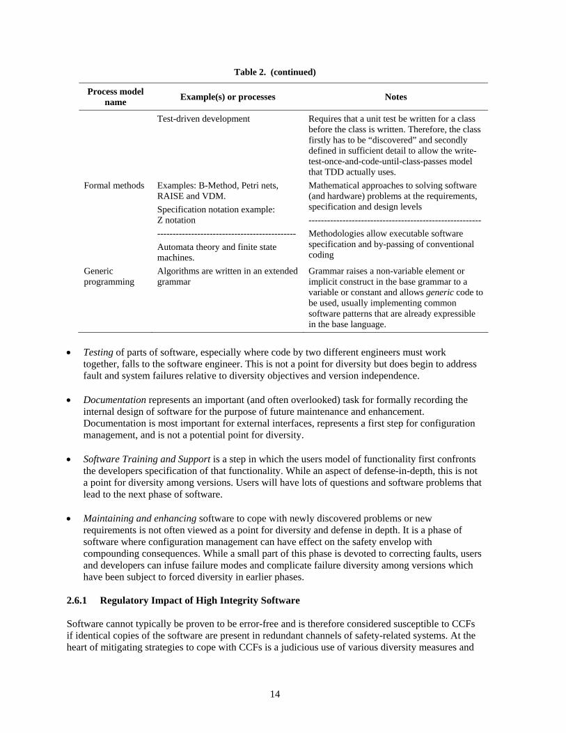
Table 2. (continued)
Process model name Example(s) or processes Notes
Test-driven development Requires that a unit test be written for a class before the class is written. Therefore, the class firstly has to be “discovered” and secondly defined in sufficient detail to allow the write-test-once-and-code-until-class-passes model that TDD actually uses.
Formal methods Examples: B-Method, Petri nets, RAISE and VDM. Specification notation example: Z notation --------------------------------------------- Automata theory and finite state machines.
Mathematical approaches to solving software (and hardware) problems at the requirements, specification and design levels -------------------------------------------------------- Methodologies allow executable software specification and by-passing of conventional coding
Generic programming
Algorithms are written in an extended grammar
Grammar raises a non-variable element or implicit construct in the base grammar to a variable or constant and allows generic code to be used, usually implementing common software patterns that are already expressible in the base language.
• Testing of parts of software, especially where code by two different engineers must work
together, falls to the software engineer. This is not a point for diversity but does begin to address fault and system failures relative to diversity objectives and version independence.
• Documentation represents an important (and often overlooked) task for formally recording the internal design of software for the purpose of future maintenance and enhancement. Documentation is most important for external interfaces, represents a first step for configuration management, and is not a potential point for diversity.
• Software Training and Support is a step in which the users model of functionality first confronts the developers specification of that functionality. While an aspect of defense-in-depth, this is not a point for diversity among versions. Users will have lots of questions and software problems that lead to the next phase of software.
• Maintaining and enhancing software to cope with newly discovered problems or new requirements is not often viewed as a point for diversity and defense in depth. It is a phase of software where configuration management can have effect on the safety envelop with compounding consequences. While a small part of this phase is devoted to correcting faults, users and developers can infuse failure modes and complicate failure diversity among versions which have been subject to forced diversity in earlier phases.
2.6.1 Regulatory Impact of High Integrity Software Software cannot typically be proven to be error-free and is therefore considered susceptible to CCFs if identical copies of the software are present in redundant channels of safety-related systems. At the heart of mitigating strategies to cope with CCFs is a judicious use of various diversity measures and
14

an analysis of how each diversity measure can cope with particular categories of CCFs. NUREG/CR-6303 identifies six attributes of diversity as follows:
• design diversity, • equipment diversity, • functional diversity, • human diversity, • signal diversity, and • software diversity. The role of software diversity in assuring adequate defense against CCF needs to be studied. In general some of the unresolved issues in using diversity and defense-in-depth (D&DinD) continue to be the following: 1. How much D&DinD is adequate? 2. What sets of diversity attributes can be used to identify adequate D&DinD? 3. Are there accepted best practices for approaching D&DinD, and if so what are they? 4. How much credit can be taken for built-in quality of a digital safety system? 5. Are there standards that can be endorsed for use by applicants in the design and analysis of I&C
systems for adequacy of the D&DinD approach? 2.7 I&C Architectures for New Plants A review of I&C features for several new reactor designs indicate fully digital and network architectures, with analog trip backup in some cases. A representative design—U.S. Evolutionary Pressurized Reactor (EPR) by AREVA NP—is briefly described herein to illustrate the general trend. Variants of the European Pressurized Reactor (EPR) The EPR (the U.S. version is called the Evolutionary Pressurized Reactor) is designed by Framatone Advanced Nuclear Power (FANP), an AREVA and Siemens company, and is considered the latest in PWR advancement. The reactor is currently under construction in Finland and designated as unit 3 of the Olkiluoto plant [(OL)-3]. Three variants of the EPR design are either under construction [e.g., OL-3 and Flamanville (FL)-3 in France] or undergoing design certification [i.e., the U.S. EPR]. A summary of the differences among the three EPR I&C variants is outlined in Table 3.
Table 3. Differences in I&C among the different EPR designsa
System OL-3 FL-3 U.S.
Protection System (PS)
TXS TXS TXS
Safety Automation System (SAS)
TXP TXP TXS
Reactor Control, Surveillance, and Limitation (RCSL) System
TXS TXS TXS
Process Automation System (PAS)
TXP TXP TXP
15

Table 3. (continued)
System OL-3 FL-3 U.S.
Priority Actuation and Control (PAC) System
TXS (priority modules) Switchgear cabinets TXS (priority modules)
Safety Information and Control System (SICS)
Mostly conventional I&C, limited QDS
Mostly QDS, limited conventional I&C
Mostly QDS, limited conventional I&C
Process Information and Control System (PICS)
TXP TXP TXP
Severe Accidents Automation System (SAAS)
TXS See note 1b TXS
Diverse Protection Functions
TXP/HBS TXP TXP
aLegend: PS—Protection System; SAS—Safety Automation System; RCSL—Reactor Control, Surveillance, and Limitation system; PAS—Process Automation System; PACS—Priority Actuation and Control System; SICS- Safety Information and Control System; PICS—Process Information and Control System; SAAS—Severe Accident Automation System; TXS—TELEPERM XS; TXP—TELEPERM XP; QDS—Qualified Display System; HBS—Hardwired Backup System.
bNote 1: No information available. 2.7.1 System-Level I&C Architecture for the EPR
Figure 2 is a block diagram illustrating the main I&C systems and subsystems of the EPR. These systems and subsystems are also listed in the first column of Table 3. In this configuration, all functions necessary to provide a safe shutdown state are either automatically generated in the SAS or manually initiated and processed by the PICS and SAS. Both safety-related and nonsafety-related actuators are monitored and controlled by PAC modules, where each actuator is controlled by a separate PAC module. Figure 3 shows a block diagram of a PAC module. All commands and control signals to one actuator pass through one PAC module. When an actuation request is issued, the PAC will respond by processing the request according to command priority encoded into the logic circuitry of the module. As a result, a command output is generated and sent to the actuator. The PAC input signals can include status and health monitors for the actuator it controls. Depending on the current operational situation, contradictory commands may be given by different I&C subsystems to particular actuators. Consequently, prioritization rules have been established and encoded into each PAC module to resolve any conflicting commands in a manner allowing the unit to respond only to the highest priority command. Each PAC module has two major components as shown in Figure 3. The first component is a programmable logic device (PLD) consisting of interconnected logic gate arrays. The second is PROFIBUS controller in the form of an ASIC. The PROFIBUS controller provides the communication interface to the TELEPERM XS (TXS) of the PS, RCSL, or the SAAS, or the TELEPERM XP (TXP) of the SAS. The RCSL system provides automatic, manual, and monitoring functions to control and limit the main reactor and nuclear steam supply system parameters. When these parameters deviate from the desired operational values, before the parameters reach trip set points, the RCSL system would take effect. This action by the RCSL system tends to
16

REMOTE SHUTDOWN STATION (RSS)
QDS
CNV
PICS
PLANT DISPLAY
SICS
QDS
CNV
PICS
PLANT DISPLAY
SICS QDS
CNV
PLANT DISPLAY
PLANT DISPLAY
PICS
MAIN CONTROL ROOM
TECHNICAL SUPPORT CENTER (TSC)
I&C SERVICE CENTER
PS SAS
PACS
PLANT EQUIPMENT (SENSORS AND ACTUATORS)
PICS Computer
Level 2
Level 1
RCSL PAS
I&C ENGINEERING WORKSTATIONS
Level 0 (Process
Level 1 (System Automation)
Level 2 (Unit Supervision And Control)
Safety I&C Operational I&C
Safety Operational
QDS: Qualified display CONV I&C: Conventional
Figure 2. EPR I&C architecture.
Figure 3. Block diagram of the EPR PAC module.
17

reduce reactor trips and PS challenges. For example, the RCSL is designed to take actions such as runback of power if the plant operational parameters exceed their operational boundaries to prevent challenging the PS. The main purpose of the SAS is to control certain safety-related support systems, such as the component cooling water system (CCWS) and ventilation. The PAS, on the other hand, controls nonsafety-related systems, and also contains some backup functions for reactor trip and actuation of ESF that are implemented using diverse hardware and software from the primary reactor trip and ESF actuation systems. The PAS is implemented with the TXS platform. The basic building blocks of the TXS system architecture can be grouped into the following categories: 1. System hardware: The TXS selected hardware platform uses a processing computer module,
which includes random access memory for the execution of programs;, flash erasable and programmable read-only memory (FEPROM) for storing program code, and electrically erasable and programmable read-only memory (EEPROM) for storing application program data.
2. System software: The TXS consists of a set of quality-controlled software components. The execution of the software centers on the operating software system that was developed by Siemens specifically for the TXS system. The operating system communicates with the platform software and application software. The platform software includes the runtime environment program that provides a unified environment for execution of the function diagram modules.
3. Application software: The application software performs plant-specific TXS safety-related functions using function block modules, which are grouped into function diagram modules. The application software is generated by SPACE tools that use qualified software modules from a function block library to construct a specific application.
Important software features of the TXS can be outlined in the following:
• Strictly cyclic processing of application software—the system processes data asynchronously, that is, there is no real time clock with which redundant processors can synchronize.
• No dynamic memory allocation—each variable in the application program has a permanent dedicated location in memory. This prevents memory conflicts typically caused by dynamic memory allocation.
• No process-driven interrupts. The SAS is a digital I&C system dedicated to automatic and manual control, as well as measuring and monitoring functions needed to bring the plant to a safe shutdown state. It receives process data from plant instrumentation and switchgear, sends actuation signals either directly or via the PAC, and sends monitoring signals to the SICS and PICS. The SAS functions include postaccident automatic and manual control as well as the monitoring functions needed to bring the plant to the safe shutdown state and automatic initiation of I&C functions to prevent spurious actuations that could result in design basis accidents. Communication Each I&C system manages its own internal exchanges (including data exchange between divisions) without using external resources. Data exchange between the different I&C systems is performed
18

primarily through standard exchange units connected to the corresponding system networks.*,21 Nothat OL-3 uses two-way communication between PICS and PS/SAS.
te
ode of Sensor Signal Transmission and Shared Sensor Implementation
g
Inca sm
hile t he
auto I&C the
Thecom
) i oftware life cycle including V&V, tion locks, and
2.7.
The e safe ety panel located in the control room, as shown in Figure 4 (MSI is not
h is classified as safety Class 1E, also serves as a safety-related gical barrier between the rest of the safety system and the nonsafety interfaces. The MSI computer
ce Unit) to a safety channel can be performed only fter that channel has been turned off via a keyswitch.
stic uto Channel
heck feature). Many precautions are taken to prevent access through the MSI from affecting the hese precautions include strict access control features and predefined
onnection/messaging protocols. In addition, the MSI confirms the identity and bypass status of a
granted, it is possible to alter the parameters of the safety application’s logic blocks. The MSI also provides a connection to plant computers, but it is a one-way uplink.
M Most sensors use 4- to 20-mA (or in some cases 0- to 5-V) analog transmission. There is no sharinof sensors between functionally diverse subsystems (i.e., between sensors on subsystem A and sensors on subsystem B).22 However, partial trip data are shared between divisions for voting rights. Sensor signals are also shared for the purpose of signal validation. Hardwired Backup Systems
orporated in the OL-3 design is an automatic hardwired backup system (HBS). The HBS contains all subset of the protection system functions. They include automatic actions needed to cope with
certain design basis events. The HBS uses FPGA technology. The FPGA is not programmable wins alled, and it is considered sufficiently diverse from the other major platforms. In addition to t
matic HBS, a manual HBS is also provided.
Design Features to Reduce the Probability of Unintended Behaviors and/or Latent Faults in Safety System(s)
I&C design features include (1) deterministic processing, (2) asynchronous operation of each puter—extensive self-monitoring, (3) signal validation techniques, (4) voting techniques, nherent and engineered fault accommodation techniques, (6) s(5
(7) operating experience with standard library of application software func(8) communication independence measures.
2 Digital I&C Issues and How They are Addressed in the EPR
monitoring and service interface module (MSI) forms the boundary and interface between thty system and the saf
shown in Figure 2). The MSI, whiclois designed to ensure that only predefined messages are transferred between the safety system and nonsafety-related displays; it is not responsible, however, for plant control functions. Communication via the maintenance panel (Servia The MSI is in continuous communication with the safety divisions to receive status and diagnoinformation. This information includes continuous checks for sensor deviation (the ACsafety function. Tcsafety division to ensure that maintenance access is enabled only for one division at the same time and when that division is in bypass. However, once access to a safety division through the MSI is
*This information primarily pertains to the U.S. EPR. While specific information on communication methodology for the OL-3 could not be obtained, the I&C architecture and communication methods for the OL-3 and US EPR are similar.
19

Figure 4. The MSI forms a logical boundary between the rest
of the safety system and the nonsafety interfaces.
sed by a sent to the SICS display; therefore, there is no
.
nsmission of
corrupted data (e.g., due to a single failure) in software-based systems as a result of some latent
Functional and Data Independence Between Safety and Nonsafety Systems or Between Safety
m a
It
er y flaw that could be exploited
as part of a cyber attack. The flaw could be a design oversight: malicious online modifications are
The SICS consists of a small inventory of conventional (continuously visible) human-machine interface (HMI) and a series of qualified displays (QDS). The QDS are safety-related and are therefore required to be qualified to Finnish Class SC-2 (U.S. Class 1E) standards. Nonsafety-related information can be displayed on the SICS. Any nonsafety data displayed on SICS is processafety-related Class 1E computer before beingco-mingling of safety and nonsafety software on the SICS display system 2.7.3 Regulatory Impact of Fully Digital I&C Architectures in NPPs Regulatory issues include the following:
• The Potential for CCF Due to Identical (Software) Functions in Modules in Redundant Channels or Divisions. In addition to the traditional CCF triggering mechanisms (environmental stressorsand signal transient(s) resulting from a common external source), the sequential tra
propagation mechanism(s), also may result in the failure of multiple trains.
•Divisions. The sequential execution of instructions in digital systems, along with response time requirements, makes it especially important that a safety system should not depend on data frononsafety (or another safety) system to perform its safety function.
• Cyber Security Issues. It becomes crucial that each subsystem (whether safety or nonsafety) be
critically examined to identify any potential for intrusion from any source, external or internal. is important here to note that the potential for a cyber threat should not only be reviewed from the point of view of how an external source can be prevented from gaining access to the system undconsideration. A subsystem can be a plant vulnerability if it has an
not required if a vulnerability already exists. The broader issue, in this case, is whether or not a
20
design flaw exists in a subsystem that could be exploited via any communication line connected to the subsystem under consideration.
• Diversity and Defense-in-Depth Issues. For fully digital systems where the backup system is also
digital, the issue of having adequate defense-in-depth becomes significant. Per BTP-19 (a software), CCF is a beyond design basis event. Thus, adequate coping is judged based on best estimate analysis methods. These include nominal initial plant conditions and concurrent failure assumptions. There should be significant functional and equipment diversity within the control systems, within the safety systems and between the control and safety systems, and it should be demonstrated that such diversity considerably limits the probability for CCF. Finally, defense-in-depth coping analysis should conservatively be based on the assumption that the CCF affects all digital control and protection systems in their entirety and that all the control and safety functions controlled by the primary safety platform are disabled.
21

3. DOWNSELECTED FOCUS AREAS
3.1 Rationale for Downselection A task of the Emerging Technologies project (Task 2) is to screen the technology focus areas for the most relevant emerging technologies that are likely to be employed in future safety-related applications. In this chapter, we identify specific technology areas screened from the focus areas discussed in Chap. 2. The screening is based on (1) the likelihood that the technology will be used in the nuclear industry and (2) the amount of available information on the technology that could support regulatory decision making. 3.2 Screened Technologies Based on the Review We consider that continued advances in the following technology focus areas need to be followed closely because these are the most likely to have the most regulatory impact with regard to nuclear power plant I&C. 1. Microprocessors and Other Integrated Circuits The growing system complexity of semiconductor devices will make it quite difficult to guarantee delivering future products free of errors. The successful development of high-k transistor ICs, and the potential for multigate transistor ICs, will revolutionize IC manufacturing procedures. This could also introduce new aging phenomena, higher sensitivity to environmental conditions (temperature, radiation), and other issues related to qualification methodologies. The use of “complex” devices such as FPGAs in safety systems need to be carefully reviewed because such devices have the potential to be reconfigured, and reconfigurability increases reuse and the potential for adversely affecting a safety function. Use of FPGAs in safety systems also brings to focus the issue of how much V&V should be required. In the area of micro-electromechanical systems devices (MEMS), current research to improve system reliability is geared toward the development of devices with enough intelligence to reconfigure circuitry when damage occurs, as a self-healing measure. While such devices are still in the future and are not planned for any of the Gen III+ plants reviewed, progress in this area should be followed so that their regulatory implication will be carefully studied at the appropriate time. 2. Communication and Networking I&C architectures in new plants will make extensive use of digital communication, both between safety systems and between nonsafety and safety-related systems. One of the more significant regulatory implications here is maintaining not only physical and electrical independence, but also data independence between safety and nonsafety systems, thereby guaranteeing that a failure in one channel or division will not cause the failure of another channel or division. The Nuclear Regulatory Commission’s Interim Staff Guidance DI&C-ISG-04, “Highly-Integrated Control Rooms—Communications Issues (HICR),” addresses some of these issues. In addition, Kisner et al. have documented in a NUREG/CR23 the technical basis for guidance that includes issues related to communication among safety divisions and between safety-related equipment and equipment that is not safety-related. The report examines (1) accepted networking consensus practices adopted by various standards organizations in the United States and internationally, (2) operating experience of
23

international power reactor ety systems, and (3) failure mechanisms arising from several possible network architectures and message types. This NUREG/CR uses this study as a basis to develop a structured approach to provide review guidance
nonsafety-to-safety communications systems. Based on the ni R, Korsah et al.24 provides review
unications in nuclear power plants. Wireless systems are likely to be e ostics and maintenance systems, inventory g to employees and field crews.
s utilizing digital network communications in saf
for the evaluation of safety-to-safety andch cal basis/acceptance criteria provided in this NUREG/Cte
procedures to guide the licensing of safety-critical display and control system design development activities and products in accordance with the requirements of 10 CFR 50.55a(h), associated standards, and regulatory requirements. The independence issue is not so easily resolved with regard to wireless communications systems in nuclear power plants. Howlader et al.7 have developed the technical basis for regulatory guidance on
plementing wireless commimlimit d in the foreseeable future to nonsafety-related diagn
ana ement systems, and voice and data communicationsm 3. High Integrity Software
lthough advancesA in software engineering have not kept pace with hardware, continuing evolutions ould continue to be followed because it has the
e systems. The present regulatory position is that if
and new methodologies in high integrity software shot ntial to reduce the probability of CCF in digital p
software cannot typically be proven to be error-free and is therefore considered susceptible to CCFsidentical copies of the software are present in redundant channels of safety-related systems. The current mitigating strategy to cope with CCFs is to apply various diversity measures, along with a defense-in-depth philosophy. These measures, along with a highly reliable software development strategy, can reduce the probability of CCF to an insignificant level. 4. Sensors and Measurement System Technologies The key regulatory issues associated with sensors and measurement systems in nuclear power plants include response time requirements, accuracy and reduced uncertainties to take credit for reduced
perating margins, and how much credit can be taken foo r increasing calibration intervals due to online
in I&C Architectures for NPPs
of tent
sensor diagnostics or inherent lack of drift (e.g., Johnson noise thermometry). Although the sensing technologies that appear to be emerging into use in the nuclear power industryrepresent adaptations of well-established measurement concepts, advances should continue to be followed, because sensors and measurement technologies have a significant regulatory impact as numerated above. e
.3 Implications of Current Trends 3
I&C architectures for new plants are characterized by extensive use of digital communication, networks, and multiplexing. Some of the regulatory implications include the following: • The Potential for CCF Due to Identical (Software) Functions in Modules in Redundant Channels
or Divisions. In addition to the traditional CCF triggering mechanisms (environmental stressors and signal transient(s) resulting from a common external source), the sequential transmissioncorrupted data (e.g., due to a single failure) in software-based systems as a result of some lapropagation mechanism(s) also may result in the failure of multiple trains.
24

• Functional and Data Independence Between Safety and Nonsafety Systems or Between SafetyDivisions. The sequential execution of instructions in digital systems, along with response timrequirements, makes it especially important that a safety system should not depend on data fromnonsafety (or another safety) system to perform its safety function.
• Cyber Security Issues. It becomes crucial that each subsystem (whether safety or nonsafety) be
critically examined to identify any potential for intrusion from any source, external or inteis important here to note that the pote
e
a
rnal. It ntial for a cyber threat should not only be reviewed from the
point of view of how an external source can be prevented from gaining access to the system under
-Depth Issues. For fully digital systems where the backup system is also digital, the issue of having adequate defense-in-depth becomes significant. Per BTP-19, (a
-in-ll ons
consideration. A subsystem can be a plant vulnerability if it has any flaw that could be exploited as part of a cyber attack. The flaw could be a design oversight: malicious online modifications arenot required if a vulnerability already exists. The broader issue, in this case, is whether or not adesign flaw exists in a subsystem that could be exploited via any communication line connected to the subsystem under consideration.
• Diversity and Defense-in
software) CCF is a beyond design basis event. Thus, adequate coping is judged based on best estimate analysis methods. These include nominal initial plant conditions and concurrent failure assumptions. There should be significant functional and equipment diversity within the control systems, within the safety systems and between the control and safety systems, and it should be demonstrated that such diversity considerably limits the probability for CCF. Finally, defensedepth coping analysis should conservatively be based on the assumption that the CCF affects adigital control and protection systems in their entirety and that all the control and safety functicontrolled by the primary safety platform are disabled.
25


REFERENCES
1. NRC Digital Research Plan for FY 2001–FY 2004, Nuclear Regulatory Commission, 2001. 2. J. M. Harper and J. G. Beckerley, Eds., Nuclear Power Reactor Instrumentation Systems
Handbook, Vol. 1, TIC-25952-P1, U.S. Atomic Energy Commission, 1973. 3. K. E. Kneidel, “Advances in Multizone Ultrasonic Thermometry Used to Detect Critical Heat
Flux,” IEEE Transactions On Sonics And Ultrasonics, SU·29(3), 152–8 (May 1982). 4. Interim Staff Guidance DI&C-ISG-04, “Highly-Integrated Control Rooms—Communications
Issues (HICRc),” U.S. Nuclear Regulatory Commission. 5. R. Kisner et al., “Technical Review Guidance and Acceptance for Digital Communications in
Highly Integrated Control Rooms,” Draft NUREG/CR, September 2007. 6. K. Korsah et al., “Procedure for the Review of Safety-Critical Display and Control Systems,”
draft ORNL letter report, November 2007. 7. M. K. Howlader, K. Korsah, and P. D. Ewing, “Technical Basis for Regulatory Guidance on
Implementing Wireless Communications in Nuclear Facilities,” ORNL/NRC/LTR-07/09. 8. R. Choi and G. Bersuker, SEMATECH, “Reliability Implication in CMOS & Gate Stack Scaling,
“IEEE International Reliability Physics Symposium (IRPS), Reliability Physics Tutorials, Phoenix, Arizona, April 15–16, 2007.
9. T. Dellin, Quick Start Micro Training LLC, “Introduction to Integrated Circuit Reliability,” IEEE International Reliability Physics Symposium (IRPS), Reliability Physics Tutorials, Phoenix, Arizona, April 15–16, 2007.
10. J. Lloyd, IBM, “Electromigration…from Black to Blech and Beyond,” IEEE International Reliability Physics Symposium (IRPS), Reliability Physics Tutorials, Phoenix, Arizona, April 15–16, 2007.
11. Personal communication, M. D. Muhlheim, Oak Ridge National Laboratory with H. Puchner, Cypress Semiconductor, April 2007.
12. D. K. Schroder, Negative Bias Temperature Instability (NBTI), Physics, Materials, Process, and Circuit Issues, Arizona State University, Tempe, Arizona, August 2005.
13 P. Parkinson and L. Kinnan, “Safety-Critical Software Development for Integrated Modular Avionics (White Paper),” Wind River Systems, Inc, 2006.
14 J. Held et al. (editors), “From a Few Cores to Many: A Tera-scale Computing Research Overview,” white paper published by Intel Corporation, 2006 (http://download.intel.com/research/platform/terascale/terascale_overview_paper.pdf).
15 Intel Web page announcement of 80-core CPU research prototype, http://www.intel.com/research/platform/terascale/teraflops.htm.
16. L. J. Bond et al., On-Line Intelligent Self-Diagnostic Monitoring for Next Generation Nuclear Plants, NERI Project # 99-168, PNNL-14304, Pacific Northwest National Laboratory, 2003.
17. L. J. Bond et al., “Improved economics of nuclear plant life management,” Second International Symposium on Nuclear Power Plant Life Management , October 15–18, 2007, Shanghai, China.
18. L. J. Bond and S. R. Doctor, “From NDE to Prognostics: A revolution in Asset Management for Generation IV Nuclear Power Plants,” Proc. SMIRT 19, August 12–17, 2007.
19. G. WIlkowski et al., “Status of Efforts to Evaluate LOCA Frequency Estimates Using Combined PRA and PFM Approaches,” 28th MPA Seminar, Materials Testing Institute, Universitaet Stuttgart, Germany (2002).
20. P. Howard, “Prognostic Technology—new challenges,” Soc. Machinery Failure Prevention Technology (Proc. 59th MFPT Soc., 3–8, Virginia Beach, Virginia (2005).
21. EPR Design Description, Framatome ANP, Inc., August 2005. 22. Ibid. 23. R. Kisner et al., “Technical Review Guidance and Acceptance for Digital Communications in
Highly Integrated Control Rooms,” Draft NUREG/CR, September 2007.
27

24. Korsah et al., “Procedure for the Review of Safety-Critical Display and Control Systems,” ORNL letter
report ORNL/NRC/LTR-XXXX, Oak Ridge National Laboratory, Oak Ridge, Tennessee.
28