ORlGUWLlY - Defense Technical Information Center 62 65877 MR February 1944 NATIONAL ADVISORY...
64
N 62 65877 MR February 1944 NATIONAL ADVISORY COMMITTEE FOR AERONAUTICS ORlGUWLlY ISSUED February 1944 as Memorandum Report THE EFFECTS OF A HIGHLY CAMBERED LOW-DRAG WING AND O F AUXILIARY FLAPS ON THE HIGH-SPEED AERODYNAMIC CHARACTERISTICS OF A TWIN-ENGINE PURSUIT AIRPLANE MODEL By Victor M. Gamer Ames Aeronautical Laboratory Moffett Field, California for Amnautia W&iW DaG WASHINGTON NACA WARTIME REPORTS are reprints of papers originally issued to provide rapid distribution of advance research results to an authorized group requiring them for the war effort. They were pre- viously held under a security status but are now unclassified. Some of these reports were not tech- nically edited. All have been reproduced without change in order to expedite general distribution. A -90
Transcript of ORlGUWLlY - Defense Technical Information Center 62 65877 MR February 1944 NATIONAL ADVISORY...
N 62 6 5 8 7 7 MR February 1944
NATIONAL ADVISORY COMMITTEE FOR AERONAUTICS
ORlGUWLlY ISSUED February 1944 as
Memorandum Report
THE EFFECTS O F A HIGHLY CAMBERED LOW-DRAG WING AND O F
AUXILIARY FLAPS ON THE HIGH-SPEED AERODYNAMIC
CHARACTERISTICS O F A TWIN-ENGINE PURSUIT AIRPLANE MODEL
By Victor M. Gamer
Ames Aeronautical Laboratory Moffett Field, California
for Amnautia W & i W DaG
WASHINGTON
NACA WARTIME REPORTS are reprints of papers originally issued to provide rapid distribution of advance research results to an authorized group requiring them for the war effort. They were pre- viously held under a security status but are now unclassified. Some of these reports were not tech- nically edited. All have been reproduced without change in order to expedite general distribution.
A -90

f o r tne '
By Victor if. Gamer
SUPiURY
.. This re?or t l?rer-en%s thl; results of t e s t s of 'a irodel o f a twin-engine -mrsu!,t sirplane, an NXCA 230-series wins 2nd. a ~ . g h ~ y c3x'cered- NXC-L &-series
r . - i t l n each of t h e wines.
Data shoving t he conyarison of t h e hiTh-speed aero- dynanic c h a r a c t e r i s t i c s of t h e Eode l :,;hen emipged T:ri.G'n each of the v i n p , t he effect o f the auxiliary cor i t ro l flaps on t h e aerod-ynamic c h e r a c t e r i s t i c s , P-nd t h e elev2tcl.r effec- t i v e n e e s for t h e illod-el v i th the & s e r i e s ~ i ing . a r e m e s e n t e d .
B-IO r-ings xere i n v e s t i p t e d ,
'* wing. Auxiliqry con t ro l f l m s ?:em t e s t e ? i n combination
INTR03UCTION

2 #
T e s t s o f s similar pir?lc.ne mo2el e t h i p h cpeed. ind.ica.ted t h a t a u x i l i w y con t ro l f l e n a 7-ere e f f e c t i v e i n m-od.ucing f o r c e s
t o qull t he e i r p l a n e out o f high-meed- dive6 ( r e fe rence 2 . It bias d e s i r e d t o determine i f such pad moaents
r u p i l i p r y con t ro l fla:3s would be e f f e c t i v e on t h e model rei2orte8 on he re in arid-, i f s o , t h e o.lntimum l o c a t i o n o f t h e flaps.
The s p e c i f i c ?ur?oses of t h e p re sen t i n v e s t i p a t i o n v e r e e s f o11oY3 :
J
1, To compare t h e hiFh--speed aerogynemic charpcter- i s t i c s o f t h e model having an KA-C-4 230-series wing T . r i t k : those of a model havine a h igh ly cambered NACA 66-series y r i i - i g
o u t fo rces ?n< momsnts, of auxiligry con t ro l F l a g s in cozbiz- a t i o n ;'it5 t h e 230-series wing
2, To determine t h e e f f e c t i v m e s s , i n mogu.cing'pul1-
3. To determine the e f f ec t iveness , in 9rod.ucing pull- ogt fo rces PTIB moments, of au f7, %@! O Q Z e t i o n T d r i t h t h e h iph ly cambere
Tdth Mach number fo l ' , the Eodel eanip2ed ?+ th t h ~ h l p h l y cc0n;- 4. To determine the variation o f e l eva to r e f f ec t iveneas 3~
bered 66-series r..ing c I
The i n v e s t i e a t i o n was conducted. i n t h e .Ames l6-foot high- speeC vind tumnel a t t he recrueat o f t h e k l r Mater ia l Ccmrnc?nd, U. S. Army hir Forces.
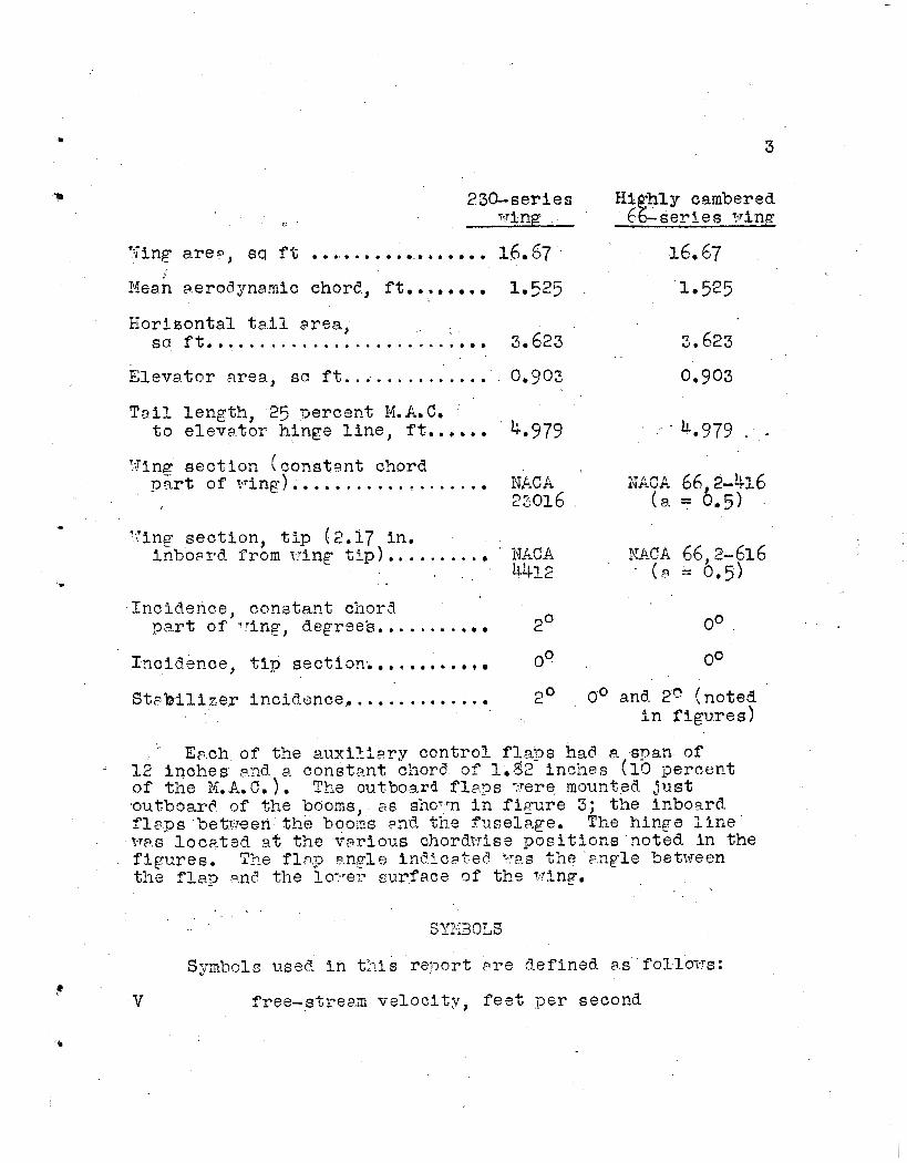
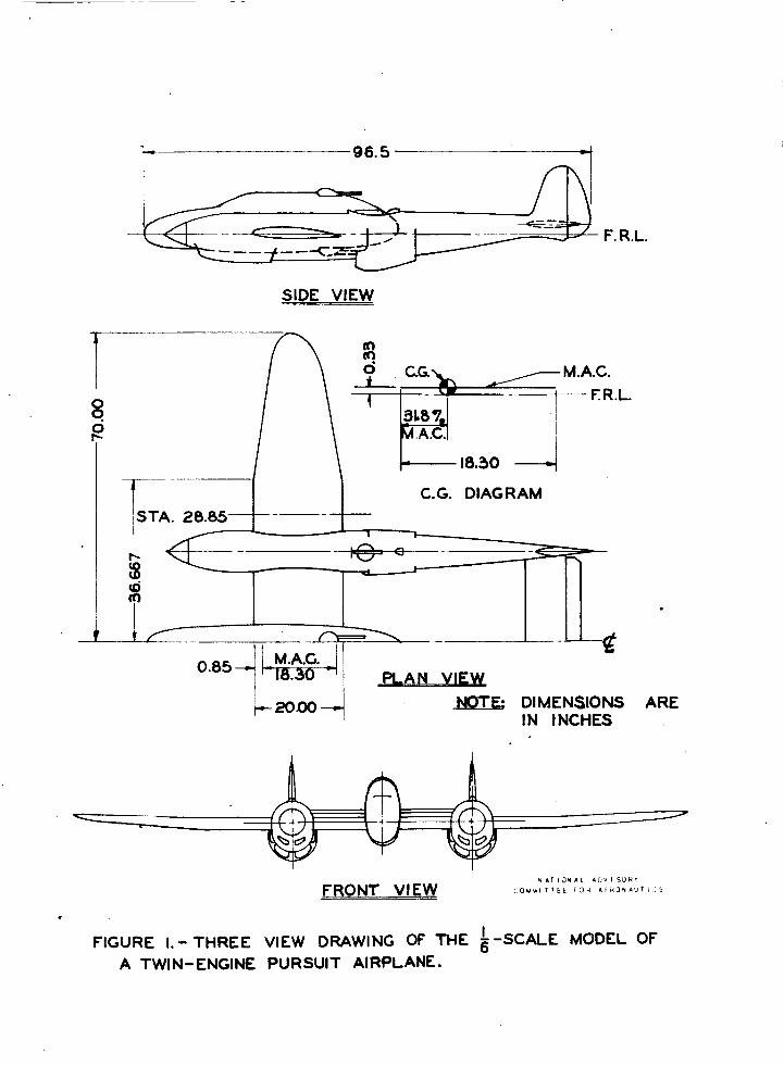
h d e s c r i p t i o n of t he model T v i t l ? t h e NACA 230-series -ring and t 3 e l a r g e booms mc.y be found. i n r e fe rence 1. The l3rF.e booms w r e used i n FII of t h e ? resent t e s t s . r -4 three-view draT.rinp.of t h e nocqel i s show^ in f i p r e 1 ~nc' .I y h o t o p ? p h o f t h e trinC-tunnel s e t u r i n fiqurc? 2. Sone o f t h e p e r t i n e n t dimensions ?re ~' i : -en i n t'ne i ' o l l o T , i v t a b l e :
4
Y
m 3
230- se r ies t*Tinp
'Cinp arer, sq f t ................. 16.67 16.67 &an aerodynanic chore, f t . ....... 1.525 1.525
Horigontal t s i l 8rea , s a f t . . . . . ...................... 3.623 3.623
E l e m t o r a rea , sa f t .............. 0.90Z 0.903
TeiL length , 25 qercent M.A.C.
>Jing - s e c t i o n (cons tan t ckord
t o e l e v a t o r hinge l i n e , ft...... 4,979 - . h.979 . .
p v t o f r.ring) ................... wCA l\lh\Jn u0,2 ? ? A n n f f -kA6 23016 (a = 0,5)
. Ying sec t ion , t i p (2.17 in .
inboprd from tying t i p ) ........... NACA NACA 66,2-616 4 1 2 ' ( P = 0.5)
oo
00
Incidence, cons tan t chord
InCid.eFCe, t i p Section; . e *
part o f .fTing, d-spree's.. ......... 2O
O0
Stsbi1ize.r incid-ence, ............. c 9' O* and- 29 (noted i n figures)
Ench of t he a.uxiliFry cont ro l fla.Fs h a d a. span of 12 i nches p.nd a cons tan t c:ior<. o r 1.~2 incizes (10 percent of the M.A.C.), Tke? outbozrd f l e g s -.rere mounted j u s t %outboar? of the 'OOGIRS, PS shorrn i n f i p u r e I 3; t h e inboard . f l ~ p s Setrreen the boons m?, %he tusela4ge, The hinge l i n e V ~ P S locPted- a t t h e v a r i o u s chord~r i se p o s i t i o n s 3oted in the f i g u r e s . '79-e f b p anple i n d i c a t e e YYJ.S t h e PnFle between t h e f l a p snil the l,o-.Te:- surface of t h e Wng.
Syiribols use8 i n t h i s r e n o r t e r e clefined P S fol .10~-rs:
v free-stream ve loc i ty , f e e t per second 1'

I 4
2 free-stream dynamic p res su re ( 4 P V 1, pounds , . Der scruare f o o t
M v . 14ack number
S :ring are,-, sqimra f e e t
IC, A. C. me~.n aerodynmic chord., f e e t
CL
CD
l i f t c o e f f i c i e n t ( l-igt)
‘drag c o e f f i c i e n t (W) Cmc, g. pitching-moment c o e f f i c i e n t
(ni tchinpmoment --- about t h e cen te r of k--- qs I % . A . C 7
cn
C
a
P
Pcr
s e c t i o n normpl-force c o e f f i c i e n t s e c t l o n no *
( ( Pos i t ive --hen a c t i n g UpT’arL)
.I
/
. , . sectian chord, f e e t
ang le o f p-.ttc?ck measured. f r o n t h e f u s e l a c e re ference
increment o f l i f t c o e f f i c i e n t due t o the ex tans ion
l i n e , degrees
of t he p u x i l i q r y f lms
o f t h e a u x i l i a r y f lPps
extension o f t h e r u x i l i a r g f l r p s OT t o t h e deflec- t i o n of the e l e v a t o r
increment o f d r p p c o e f f i c i e n t c?ue t o t h e extension
increment of pitching-moment c o e f f i c i e n t ‘due t o . the
pressure c o e f f i c i e n t
1 ( l o m i l s t e t i c p re s su re - free-stream s t a t i c p re s su re cl
vPlue of P r t which the l o c a l v e l o c i t y reaches t h e l - o c ~ l v e l o c i t y o f sound

z
?- c a c c e k e r a t i o n o f , - r ~ v i t ; y , f e e t -3er eecon6 s e r secm6.
5
L 1 o w r eu r fa c e
Angle-of-attack c x r e c t i o n ( B e g ) = 0.623 CL
Dm-g-coeff i c i e n t coxec'cion = O.CllOFr7 CL."
-~itc~?inT-sornent-cocf f i c i e n t c o r r e c t i o n = 0.01-55 CT,
No cor rec t io-w f o r f l o 7 . r i n c l i n a t i o n o r csnF2rlct ion were aT;3l.ied.
P resen ta t ion of R e s u l t c

~
f
6
Data qbtained. from t e s t s of a u x i l i m y f l q s on the & 23O-ser:os wing a r e fount i n f i g u r e s I1 t o 19 and froni t e s t s o f f laps on the &-series w:ng i n f i g u r e s 20 t o 27.
from t e s t s with the two s t a b i l i z e r angles are shown in f l y u r e s 2g and 29,
Data o'Jtained from t e a t s w i t h the elwatoor d e f l e c t e d and
DISCUSSIOX
L
I .
7 . .
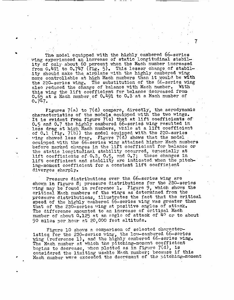
TheL model equipped with the h ighly cambered 66-series a
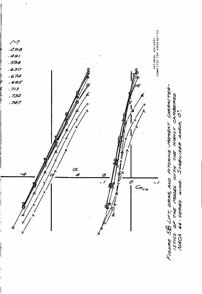
wing experienced- an increase o f s ta t ic l o n g i t u d i n a l stabil- i t y of only about 60 percent when t h e Mach number increased from 0.493. t o 0.747 (fig. 5). This l e s s e r change o f stabfl- i t y should aaka thss a i rp l ane ?*rith the h igh ly cmbered wing more con t ro l l ab le a t high Mach numbers than it tirould. be with t h e 230-series wing, The s u b s t i t u t i o n of t he &-aeries iring a l s o reduced tine change of b l a n c e v i t h Mach number, With th i s wing t he l i f t coe f f i c i en t f o r balance decreased f r o m 0.6 a t a Ifact., number. of O.bg1 t o 0.3 a t 3- Mach nurrber of 0.7 2 7.
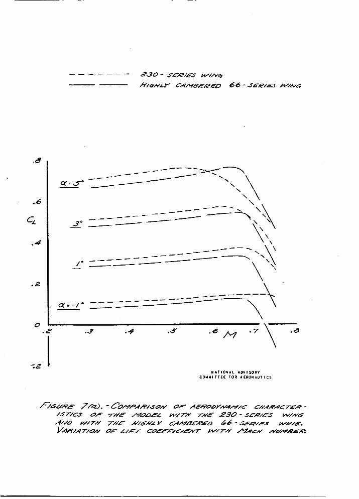
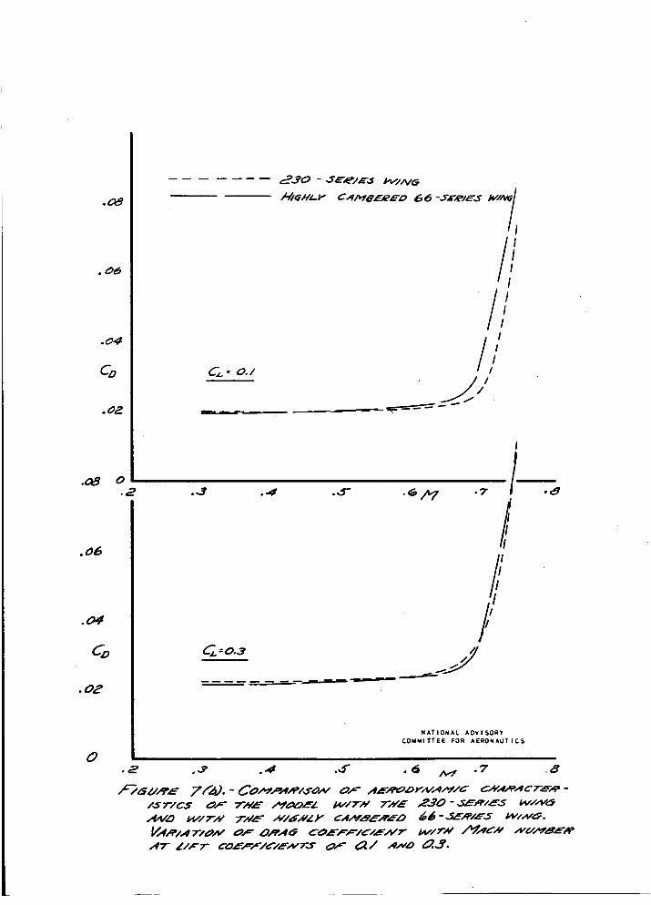
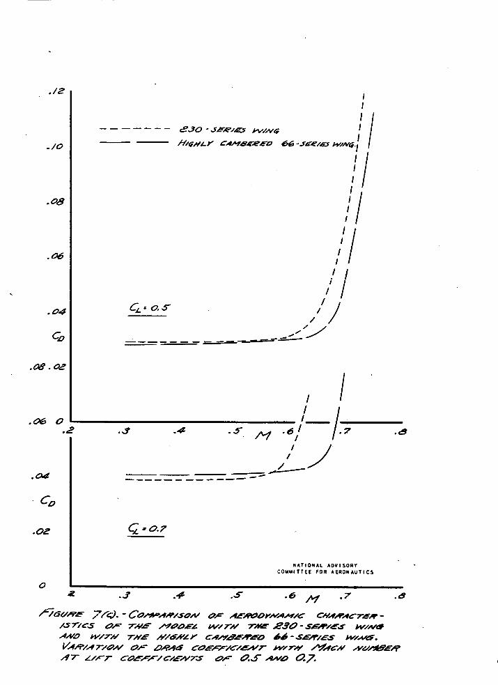
Figures 7 ( s ) t o 7(d) compare, d i r ec t ly , t he aerodynamic c h a r a c t e r i s t i c s of the mod-els equipped with t h e two wings. It i s evidcot fmrn figure 7 ( c ) that at l i f t c o e f f i c i e n t s of 9.5 and 0.7 the highly caabered 6 6 s e r i e B wing r e s u l t e d in l e s s &rag a t h igh Mach numbers, v M l e a t a l i f t c o e f f i c i e n t of 0.1 (fig. 7 ( b ) ) t h e model equipped w i t h the 230-series
eauipped v i t h the 6 L s e r i e s wine: a t t a i n e d h igher Kach numbers before mp.rked cha.nges i n t h e li?t c o e f f i c i m t f o r balance o r .. t h e s t a t i c l ony i tud ina l stc-bilitjr occurred, es?ecialLy a t l i f t c o e f f i c i e n t s of 0.3, 0.5, ?nd 0.7; t hese changes in l i f t c o e f f i c i e n t and s t a b i l i t y are i n a i c a t e d when t h e pitch- ing-moment c o e f f i c i e n t f o r i? constent l i f t c o e f f i c i e n t diverges s h a q l y .
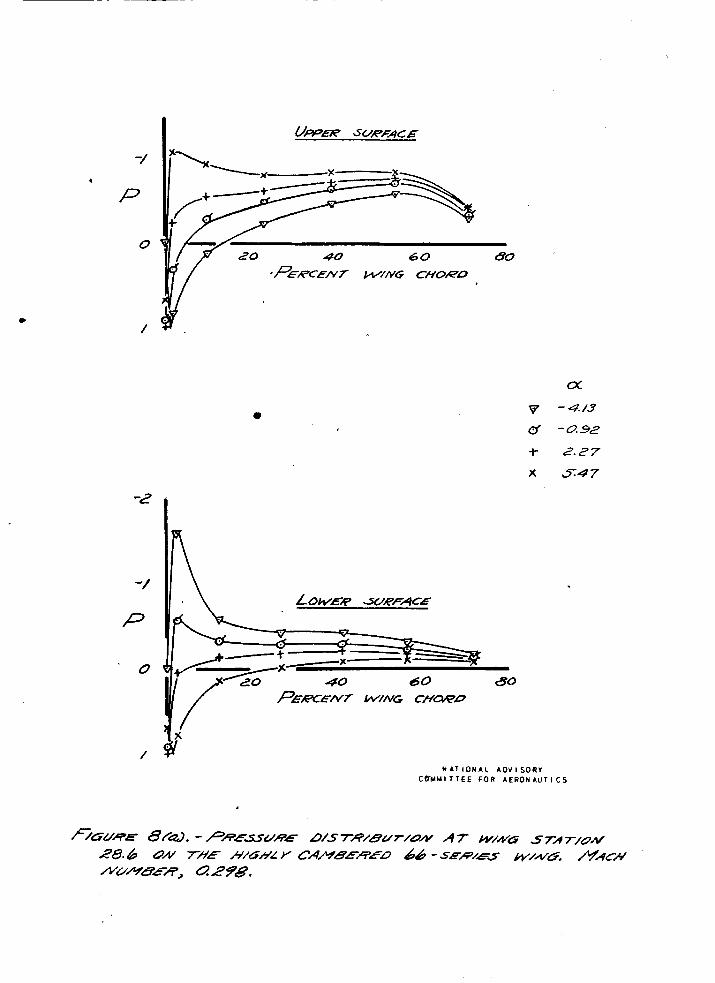
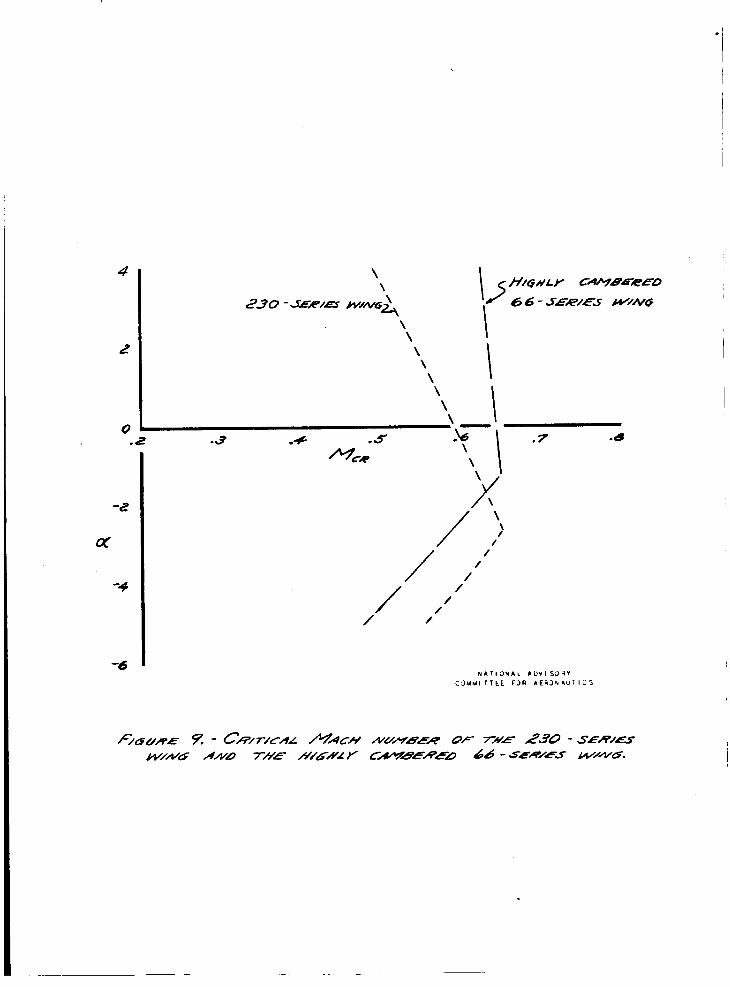
? ressure d i s t r i b u t i o n s over t he 66-series wing a re shoyn i n f i g u r e 8; pressure d i s t r i b u t i o n s f o r the 230-series :.ring may be found i n reference 1. Figure 9, which shovs the c r b t i c a l Mach numbers of t he Frinrs as determtned from the p r e s s u r e d i s t r i b u t i o n s , i l l u s t r a t e s t'ne f a c t that t h e c r i t i c a l speed bf the highly -caabereC 66-series wing vras g r e a t e r than that o f t he 2 3 0 - ~ e r i e s ?ring a t p o s i t i v e angles of att3ck. The difference mounted. t o a n increase of c r i t i c a l Mach nunber of about 0.125 st an s.r?gle of a t t a c k of bQ or t o about 90 miles ? a r hour P t 20,000 f e e t a l t i t u d e .
- Tring shoved l e s s d-ra?. Figvre 7(d) shows that the model
Figure 10 show it comFarison of s e l e c t e d chnracter- i s t i c s R f o r the ,230-serles wing, t h e low-cambered 6&-serics wing ( r e fe rence 1) , and t h e highly cambered 66-series wing. The Mr.ch number at i.thich the pitching-moment c o e f f i c i e n t begins t o decrease, vhen p l o t t e d as i n f i p r e 7 ( d ) , i s considered. t h e l i i z i t i n g usable M.ch nunibes; because if this
t I h c h number were exceeded t h e decrement of t h e T3itchingdmoment . _

8
coe f f i c i en t (cou;>led v i th the incnzase of s f a t i c longi-
The model, vhen enuipped with ths hig5lg csrnbered 66-series v i n g , had is highel- l i m i t o f usable Mach numbers a t l i f t coeff i - c i e n t s above 0.1 than i t aid when equipped v i th the 2 3 b s e r i e s wing, find. a h ighcr limit f o r l i f t c o e f f i c i e n t s .above 0.6 than aid t h nodal vhan equipped vi th t h e low-cmbered 66-ser ies ?.ring. The mrximurn l i f t ; c o e f f i c i e n t a t i? Mach nurqbqr of O e 6 with t h z highly c,qmbercd 66-series wixg W.S e s p e c i a l l y note- worthy, being a’ooirt; 1.34 P S concx-ed t o 1.1 wing ~ n t i O.$9 TheEe mrximurn l i f t c o e f f i c i e n t s correspond t o the fo l lov ing norniel PccelerPt ions at va-.riou.s a l t i t u d e s :
8
tusinnl c t s b i l i t y ) 1~ou1-d make pul-1-oats from dives d i f f i c u l t , J
f o r the 2 3 G s a r i e s f o r t h e low-cmberod & s e r i e s wing ( f i g . 10).
I , \
_.-- I i.. _ _ __ - _ _ -.&zA.EU~LCE~L-~~P.~ i o n ? a, -- 1\11 -- _- 00 6. --- -----
*
- T h i s ad8itrionr.l m~xiaum lift c o e f f i c i e n t especi,?2ly vxPu- - able f o r cl hfgh-dt!.tude f i g n t i n g h i r p l w e which m?.y be requi red t o develop l a r g o p.ccelera3ions a t high speed..
Aus i l i ? ry Control FlPps i n Cornbinatton With the 23CLSeries Wing
Yind-tunnel t e s t s of o the r mo6-els ( r e fe rence 2) i n d i c a t e that .s?lxili,-rp con t ro l f l r p s Qf t h o type used i n this t e s t usu,5ll-y cause f o r c o s an4 moments t o be developed which pro- duce p o s i t i v e normzl acze lera t ions . The r e s u l t s of refm- ence 1 8ne- of t h e p re sen t tssts i n d i c a t e t h a t the d r p l a n e w i l l d-evelop noment m d s t P b i l i t y changes a t high Ibip.ch numbers which will o p o s e racovery from h igh- sped dives. The use of e x x i l i m y c o n t r o i f 1 p - p ~ should previae add-i t ional con t ro l f o r recovery from such tiives.
n e w t h e cen te r of t h e s p m m?y r e s u l t in tcil b u f f e t i n g and Experience i n d i w t e s t h a t t h e use o f f laps on t h e vting

e 9
shaking. Becavse of' th i s considerat ion, most of t h e f laps t e s t e d i n t h i s i n v e s t i g a t i o n were i n s t a l l e d outboard of t he booms vhere t h e wing wike would have less e f f e c t on t h e t a i l ,
b
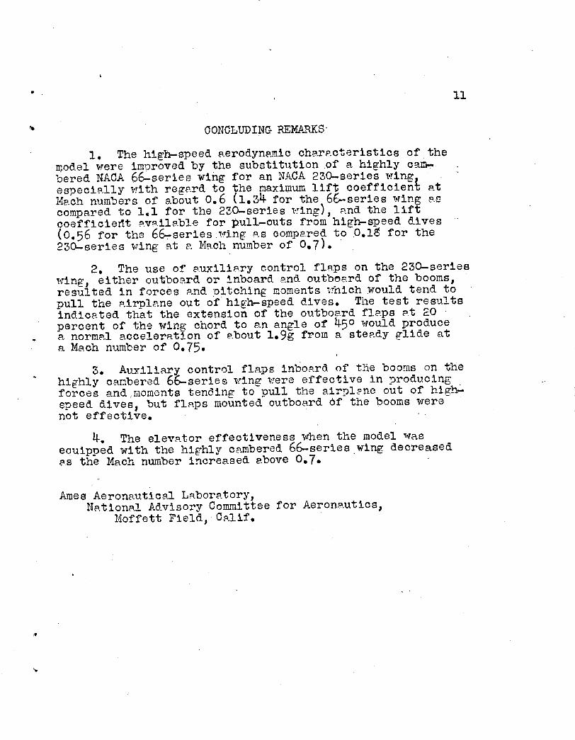
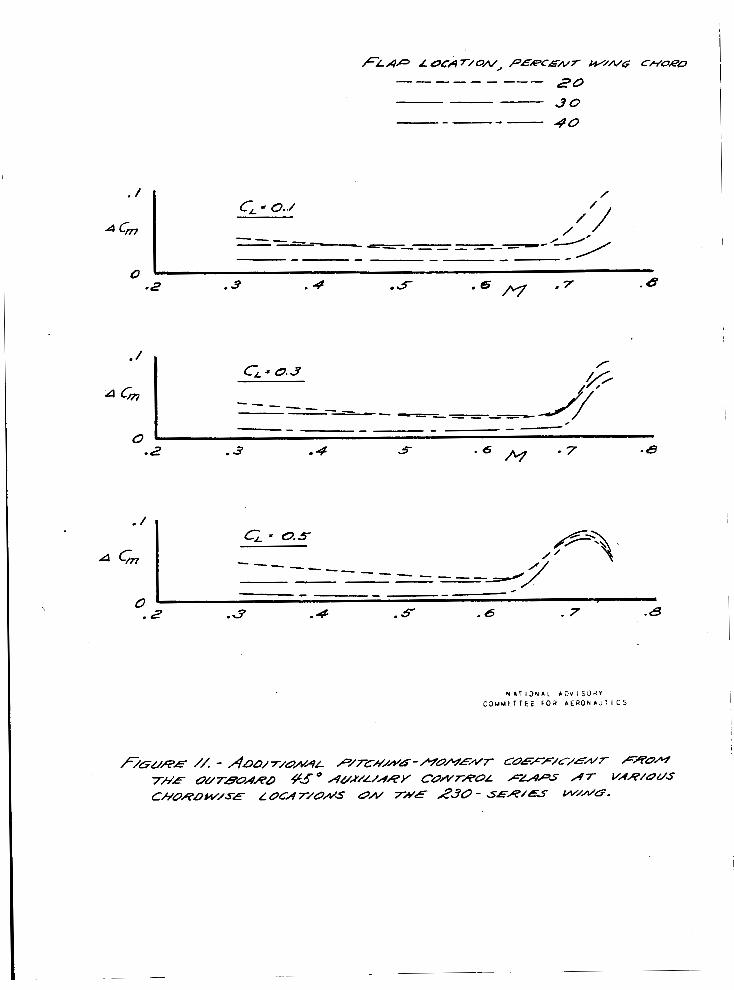
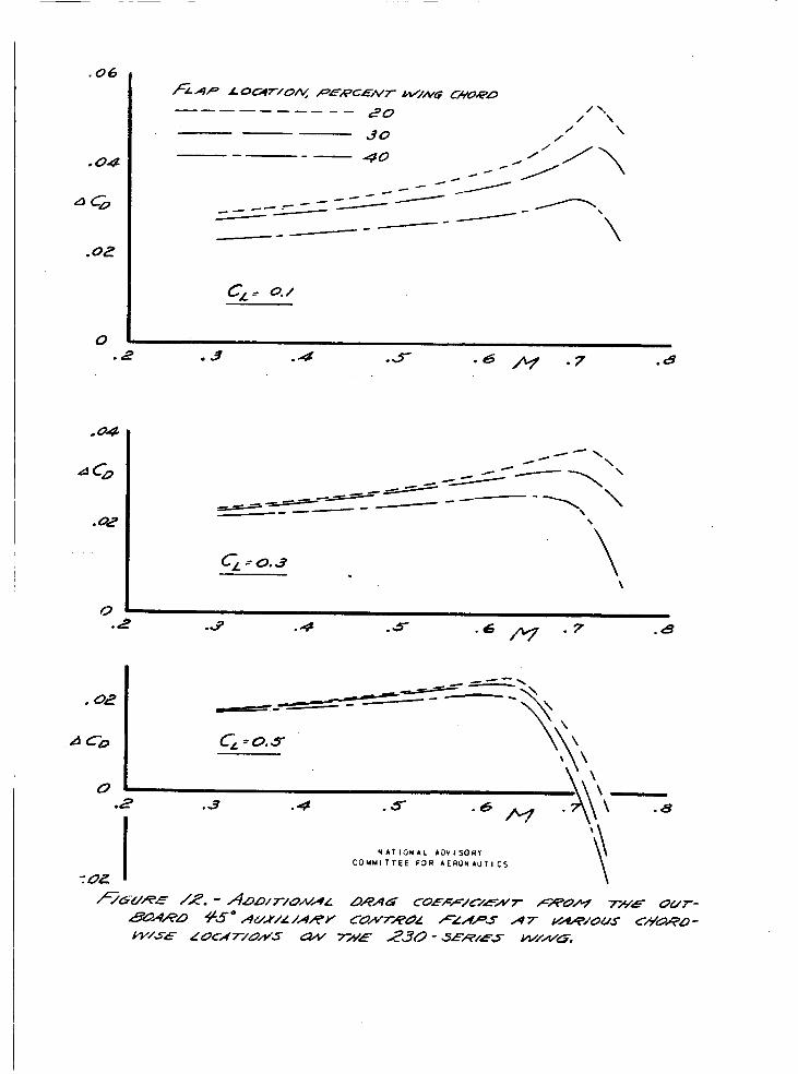
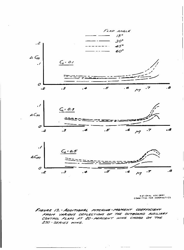
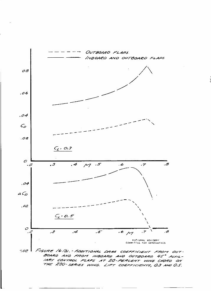
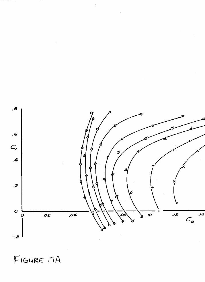
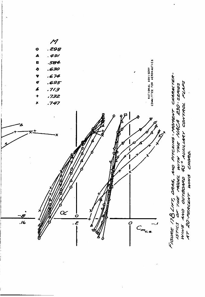
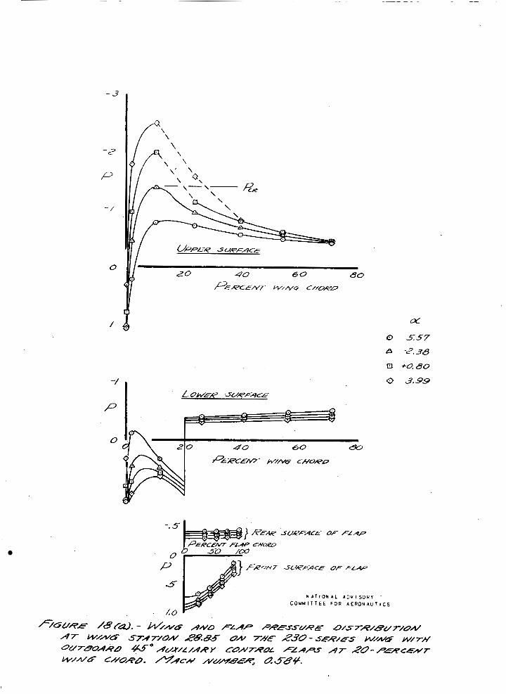
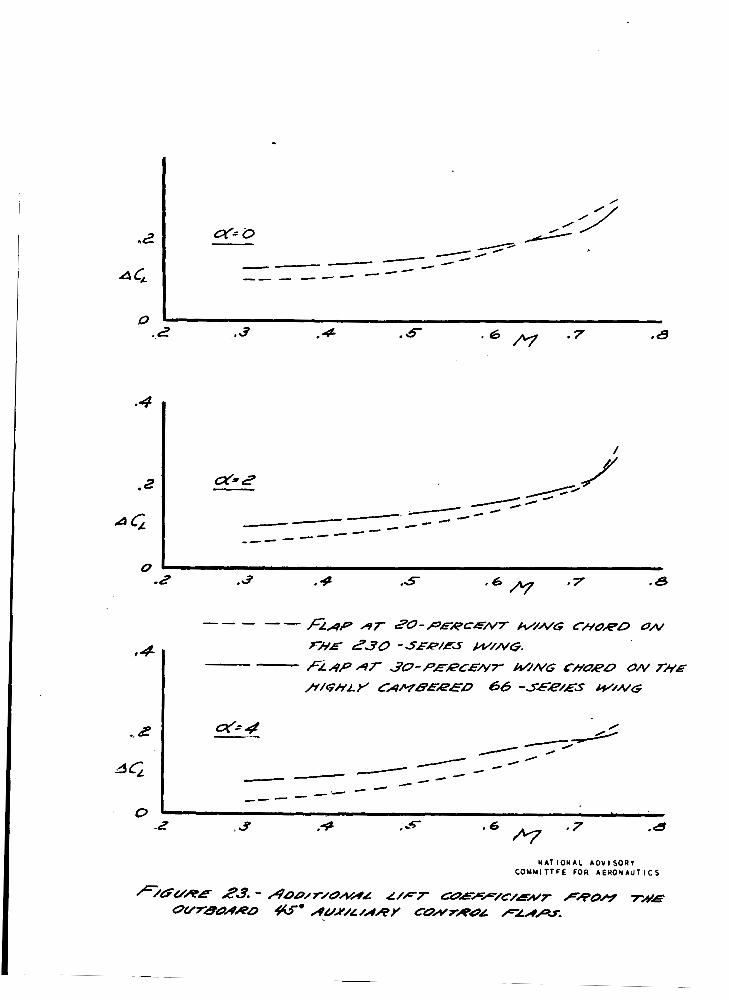
Figures 11 t o 1 6 sliotr the a a a i t i o n d pi%chin;r-mon c o e f f i c i e n t ana- drag c o e f f i c i e n t which r e s u l t e d from the f l a p s a t var ious loca t ions . U s i q l g t he c r i t e P i a that the requirement for auxiliary cont ro l flaps i s t h e development of p o s i t i v e .( clirilbinc) moments vhen t h e flaps m e de f l ec t ed , an a n a l y s i s o f the f i g u r e s ind-iccrtes that t h e 20-percent- chord loca%ion' is the\ b e s t l o c a t i o n f o r t h e outboard- flaps, and that a 45' flap opening ga.ve almost as much a d d i t i o n a l p i t c h i n g nomont as did the 60° opening. pitching-.monent c n a r a c t e r i s t l c s of t he model wi th t h e out- board 45* a u x i l i a r y f l a p s a t 20 x r c e n t o f t h e wing chord are presented i n figure 17, and TfiTini and f l a p pressure distri- buthons a r e presented i n f i g u r e 18. The f i g u r e s show tha t a t low l l f t c o e f f i c i e n t s p o s i t i v e pitching-moment-coeffi- c i e n t increments of as much as 0.1 may be expected froin the - use o f t hese f laps . Assuming t h a t t he d e f l e c t i o n of the flaps vould have no e f f e c t on the f l o a t i n g angle of t h e e l e v a t o r and u s i n g t h e f k t p - pressnted in figures &(a) and - 17, if t ho a i r p l a n e were t r i m e d i n a s teady @ide p.t a Mach number of 0,747 a t 20,000 f e e t a l t i t u d e (CL ap-oroxi- mately 0.14), t h e extension o f the f laps wou3-8- produce a normal a c c e l e r a t i o n of about 1,Yg with no fo rce or! t h e s t ick,
L i f t , drag, and
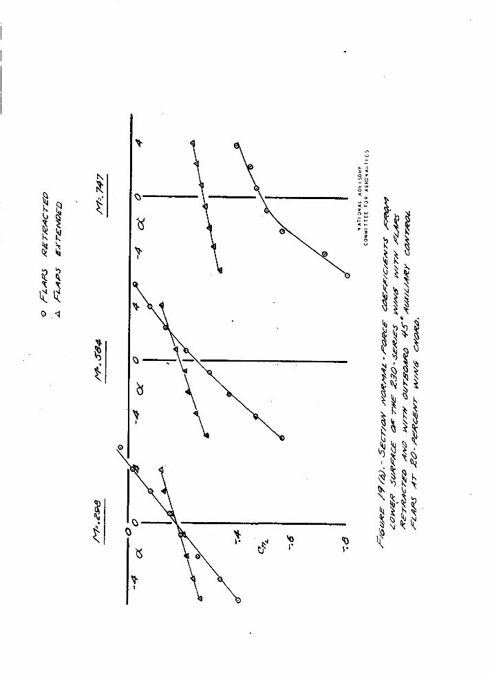
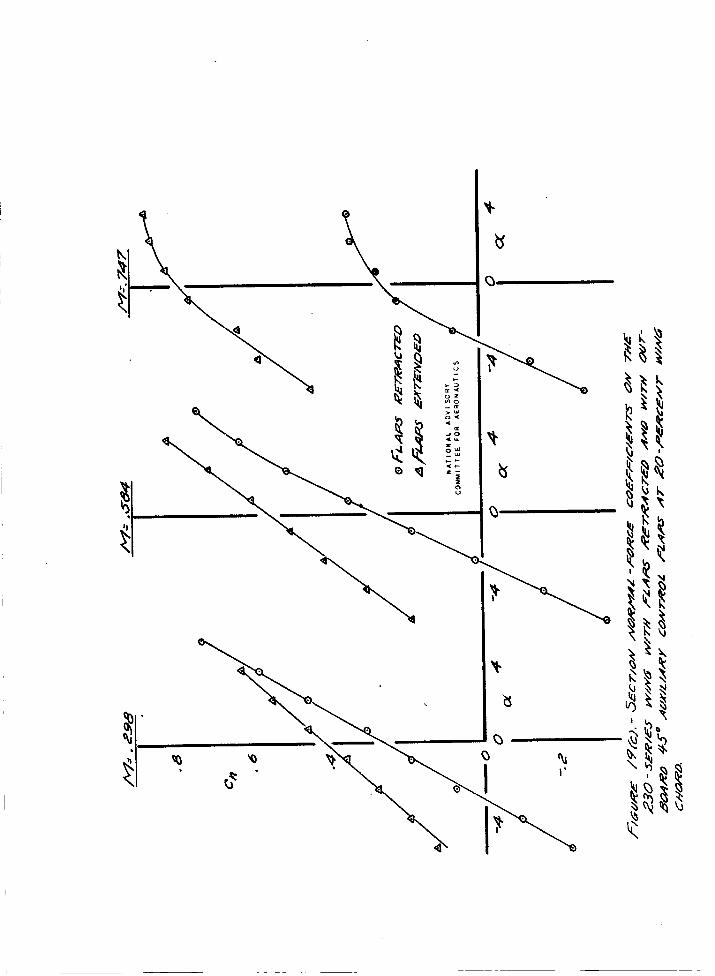
Sec t ion normal-force c o e f f i c i e n t s with the f l a p s r e t r a c t e d and vita the f l ~ p s open a r e p l o t t e d i n f i g u r e 19. These c o e f f i c i e n t s were obtain& from t h e pressure aistri- buttons. The a c t u a l mgn i tude of t h e c o e f f i c t e n t s may be subjqc t t o some e r r o r , as t h e complete pressinre d i s t r ibu - t i o n s tmx-e f a i r e d fron; da ta obtained a t only six pointB on each sur face of t he nine;. Zo.;:ever, t h e d-!ata show th3~t the t o t p.1 s e c t i on normal- f oroe coo f f i c i en t s i n c r e 3,s e d markc 81 y when tlne . f laps were ae f l zc t ea , especiRllp a t the h igher Mach numbers 'and, RS one tcould expect, t he f l p p s a ~ f f c c t e d the pressures on both t l c upper ,and 1 o ~ r e r s u r f ~ c c s of t h e . wing. The data from fo rce t e s t e a l s o shov an increpse of tho e f f e c t i v a n c s s of t h e f l 2 p s c?t the h igh k c k nmbers ( f ig . 11).

1.0
a .
(1
. .
A u x i l i a r y Corrtrol Fl.rps i n Colr?bine t i o n l?ith r' t h e Highly Cemberea 66-Series Ving
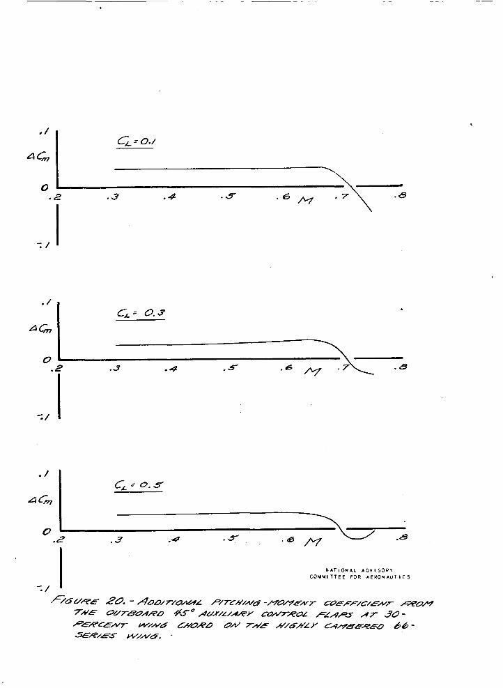
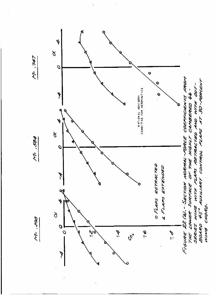
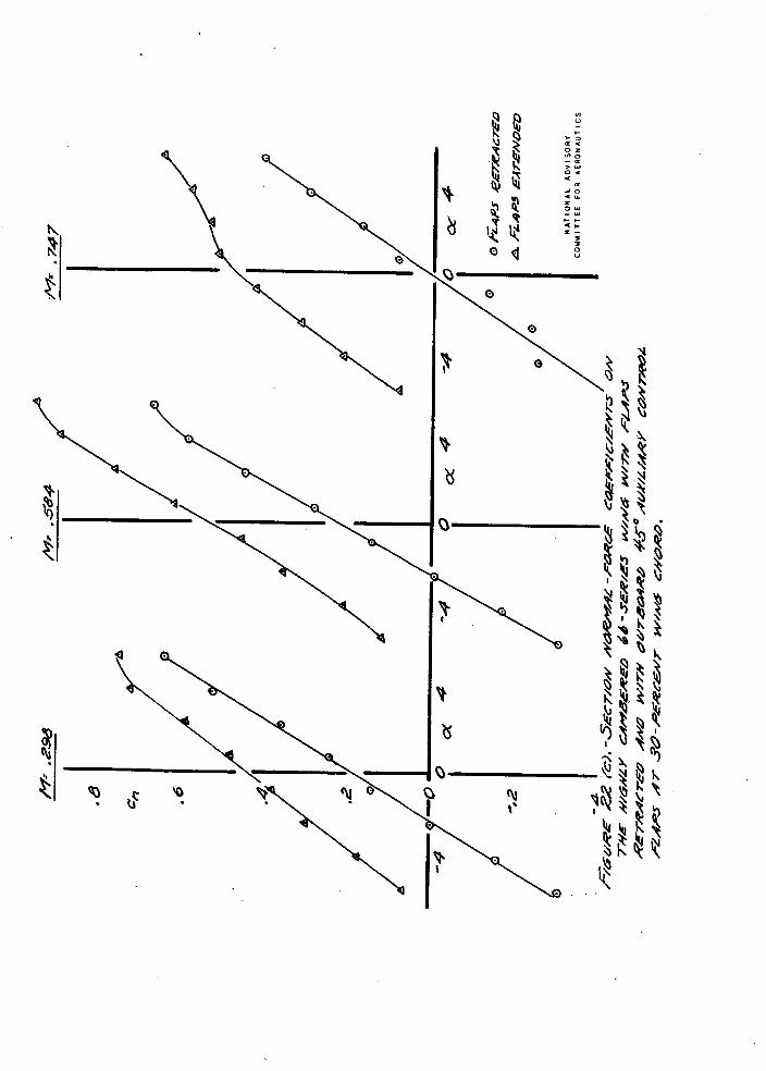
e Tests 'o f aii.kiliery c o n t r o l f l avs outbo?rc? a f . the boons cn t h e higkly. cP.Ebered 66-series :-ring showed. tliat nega t ive ( d i v i n g ) monents resul te6- from t h e f l a g s a.t nigh Mach nunkers, rather than t h e d e s i r e d c l i n b i n g moxents ( f 5 ~ . 2 G ) . Figures 19 end 22 t o 24 shcv t h a t ? h e e f f e c t of the ~1j.t3o?rd f l e ? s OR t he sec t ion no rwl - fo rce c o e f f i c i e n t , on the total l i f t c o e f f i c i e n t , 3rd 02 t h e moment of t k e q i n p v e s q u i t e simil.ar f o r the 233-series v i n g and f o r the h i k h l y d'rnbered 6 L s e r i 5 s wing; hence i t is sus lwis ing t h a t t h e - e f f ec t iveness of t he fl-aps in prod-ucing p o s i t i v e u i€chinp rnomnts m s ' not . s i m i l a r . It i s poss ib l e t k a t t he d i f f e rence i.n f'lqy sffec- t i veness vas d-ue t o a. e i f f e r e n a e in t h e i r e f f e c t op t h e down- wash a t the t a i l r e s u l t i n g from .s.- difference i n ' l i ' f t d i s t r i - bution.
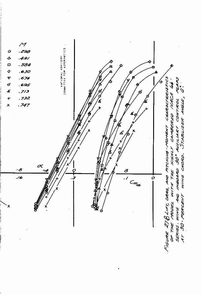
a r e shown i n f igu res 25 and i n @ mdment c h a r s - c t e r i s t i c s u at 30'percent chord. a-2 30' are shown i,n .fi i n g monent v 3 t h t he inboard f l z p s was und-oxxbtedly due t o the increased downwash a t t h e t o i l c?ysed by the ipcrease ' b f 3.2f't; c o e f f i c i e n t on t h F - t p a r t o f , th5 TS-ing J u s t aheag of t h e t a i l .
..
Elevator Ef fec t iveness * ,
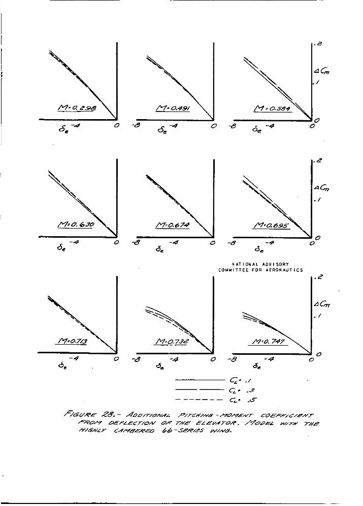
. . The e f f e c t of e l e v a t o r d e f l e c t i o n on t h e pitching-moment
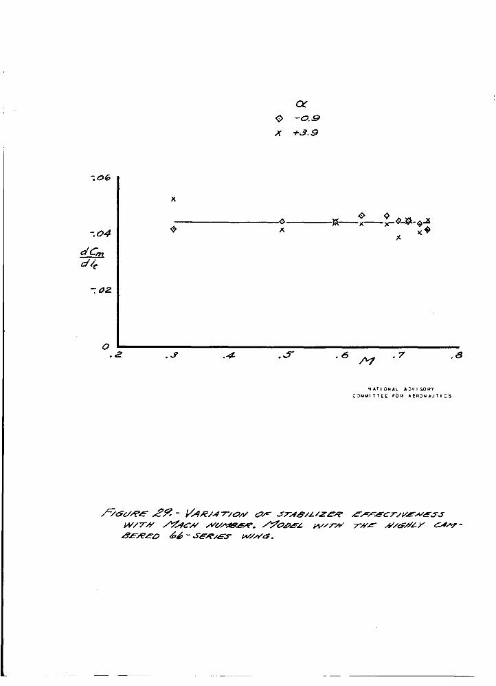
c o e f f i c i e n t vas determined- f o r t h e nod.el eauiyped T a r i t h t'ne h ighly canbered 6 L s e r i e s ?$ring. t he e l e v a t o r deflected- ? r e f'o<iid- i n P i p r e 2e. ness of t h e e l e v e t o r decre2se3 2s the PEach nimber increased above 0.7. The e l eva to r e f f e c t i v e n e s s as ?stermined s-ita t h e 23CLseriss winp on the ol.of!el d i d - not c7ecrz~se a:7:-:rec+rl?ly as t he Mpch numb& exceed-ed 0.7, as i s shown In refereri9e 1. No reason f o r t he 3 . 0 ~ ~ o f eXeVatOT e f f ' S C $ i V V I C s S 9~1th. ti:e 6&-Ser!I.€?S wing on the model is rePdiLy snpa ren t , e s ; : , a c i ~ l l y s ince %e s t a b i l i z e r e f f ec t iveness dC,/eit d- id g o t c h ~ h p 2yw.ceciably as th:7 ~ a c h nuiaber incre9s:ad ' ( f i g . 29).
The r e s u l t s o f t h e t e , c t s , v i th The e f f e c t i v e
0
r, CONCLUDING REMARKS-
11
1, The high-speed aerodynmic c h m 8 - c t e r i s t i c s of the model were innroved by the s u b s t i t u t i o n of a highly ciw bered NACA 66-series wing f o r an XACA 230-series ving esyeciKLly with r o p - r d t o t h e naximurx lift; c o e f f i c i e n t at Wech nuinSers of about 0.6 (1.34 f u r the & s e r i e s wing 9.0 compared t o 1.1 f o r the 23Lse r i e s v i n g ) , m d t h e l i f t coe f f i c i e f l t a v a i l a b l e f o r pull-outs from h i g b s p e e d fiives (0.56 f o r t he &ser ies vine 2.s conpzred t o 0.18 f o r t h e 23O-serles wing st r? Mach nurnber o f 0.7).
wing, e i t h e r outboxrd o r inboard and- outbmrd of t h e booms, r e s u l t e d i n fo rces and p i t c h i n e monents afnich would t end t o p u l l the ? . i rp lme o u t of hi@-speed dives, i n d i c s t a d t h a t t h e extension of the outboerd fl2ps p t EO percent of ths wifig chord t o a n angle of 450 would produce a n o r m 1 acceleration of p.bout l ,gg from a s t e d y g l i d e a t a Mmh number of' 0.75,
2. The use of Fuxi l iPry cont ro l flpLps on t h e 230-series
Tile t e s t r e s u l t s
- 3, Auxil iary cont ro l f h s s inboard of the booms on the h igh ly cambered 66-series v i n s vere e f f e c t i v e i n producing f o r c e s and nornants tending t o p u l l the a i rp lpnc out of high- speed dives , but flqx mounted outboard of the booms were not e f f ec t ive .
eauipped w i t h the hirhly cambered 66-series .wing decreased e s t h e Mach number increased sbove 0.7.
4. The e l e w - t o r e f fec t iveness when the model was

12
REFERENCES .-. . .,. .
1. 'Ganzer,' V ic to r 51: High-speed Wind-Tur,nel Tests Of 8 1/6-Scals Model of a Twin-E?Igine i)ur4suit AiYPlane. NACA C N I R , Dec. 1942,
.Devices f o r IEproving the Diving Characterfs t j .cs 2 , Erfckson , A l b e ~ $ L: Wind-Tunnel I n v e s t i g a t i o n of
of Airplanes. NACA C N 3 No. 3F12, 1943.
r- 96.5
SIDE VIEW
WTE DIMENSIONS ARE IN INCHES
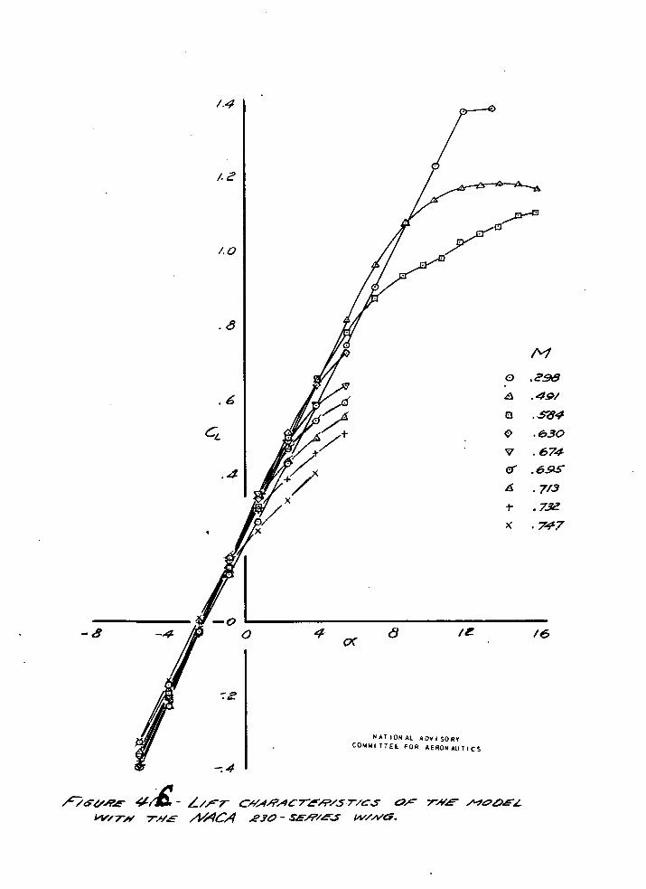
FIGURE 1.- THREE VIEW DRAWING OF THE i-SCALE MODEL OF A TWIN-ENGINE PURSUIT AIRPLANE.
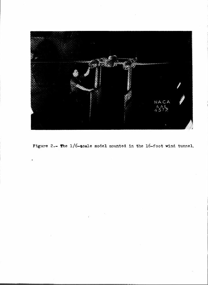
Figure 2.- The 1/6-scale model mounted in the 16-foot wind tunnel.
-
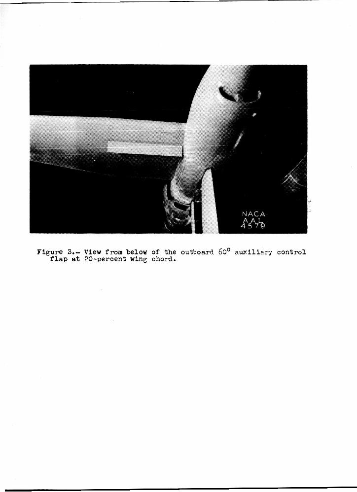
Figure 3.- View from below of the outboard 60° a u x i l i a r y f l a p a t 20-percent wing chord.
con t ro l

A 0
.
.B
. 6
G
.4
0

Q
1 Q
rQ I
.6
GL
.#
-8
/L;r
0 .tH Q .49/
a .584 0 ,630 V .674 d . 6 S d .7/3 t .72
,747

.u
I I
.6
I G
.9
.2
0
c 0
E
c P G
A
.t k
/v .298 .49/ .584
,674 ,695
. 713 ,732 .747
.630
t
1 i I I
1 1 I I
I
X
.B
..6
c,
.4
0 . /z ./6 c
K
49
.6
G
.4
.2
0 .e
2 2 I
\
.3 .s
N A T I ON A L ' A D V I SORV C O Y Y I T T E E F O R AERONAUT I C S
.a3
.06
-04
CD
-02
' I:' c-= o./
I
I-
N A T I O N A L A D V I S O R Y C O M M I T T E E FOR A E R O N A U T I C S
. /2
- /o
- 08
.a 0 .a
.m
co
. 02
0
I ' i I :/
I 1 I I
.4
20.7
.4

" I
v - .2
c so.3 L
.3 .4
c,= 0.5
\ \
UWER SURFACE
-/
P
0
/
n OL
7 -4./3
d -0.92
t 2.27
x 547
N 4 1 I O N A L A D V I S O R Y COUuITTEE FOR A E R O N A U T I C S

-/
P
0
-2
- /
P
0
/
cy
B -413
d -0.9
+ 2.29
x 550
N A T I O N A L A D V I S O R Y $f
C O M M I T T E E F O R A E R O N A U T I C S

.-/
P
0
-2
-/
”.\ \
LOWER JUPfAC€ ‘I ‘. P
0
/
a v -4.12
a -0.90
t 2.32
x 5.52

-/
P
a V -4.12
d -0.90 t 2.3/
x 5.49
W I T I O N A L AOV I S O R Y C O U M I T!EE F O R A E R O N &UT I C S

-/
P
0
v -4.24 d -/.05
t z./s x 533
-2
-/
P
0
Y A T I 3 N A L A D V 1 S O R Y C O H M l T T E E F O R A E R 3 N A U T I C S
4
2
0
-2
m
-4
-6
I \ \
I \ \ \
I \ \
I \ \ \
I \ \
/ /
/
, /
/
/% \ / \ /
/ /
/ /
/

\ \
\
\ . \ \
N A T I O N A L A D V I S O R Y - *
_. ~~
C O M M I T T E E F O R A E R O N A U T I C S
I
C, = 0.5
- --------- ----- -c - --a
01 .2 .3 .e .5 .6 .7 .a
N 4 T 1 3 N A L A C V I S O % Y C 3 M H I T T E i Foil A E R O N A U T I C S
,06
.04
dcg
. 02
0
c,= o./
.2 . 3 .4 -5- -6 /y -7 .B
.z
Acm ./
0-I
./ I
4 5 O
60"
__- - - - - - -_--
A c'= u,/
0 ' / /
----:- <L, e
-----_ - - - - -___ - --- -
N A T I O N A L A D V I S O R Y C O U M l T T E E FOR AERON AUT1 c s

. U6
-04
A co
.02
0
/"\ 0
C O Y M I T T E E FOR A E R O N A U I C
.# AG
.02
0 .2 .3 .4 . 7 ' 08
I

c,; o./

' '\ /
/ 0
0
I
/-
4-- ----- ---- e
"2 .3 .6 . 7 .6
N A T I O N A L A D V I S O R Y C O N U I T T E E F 3 R A E R O N A U T I C S
OB
.06
.04
CD
.02
0 .2
a4
0 .2
I
OU~-BOARD FLAPS. _ _ _ - - - /WBOAUD AND OUTBOARD FLAPS
CL- 0.3
\
G=0.5 \
\ \
.3 .4 .5 .7 ' .&
N A T I O N A L A O V I S O R I C O U U l T T E E F O R A E R O N A U T I C S
0
A a Q 0
Q
B + E
/\I ,298 .49/
.5w4
.630 - 6 7 4 a 69s
.7r3 8 732 ,747
- 3
-2
r > r
- /
0
/
20 40 60 &3
P fReNT SLWFACE OFFLAP
5 N A T I O N A L A D V I S O R Y
couu I T r E E F O R A E R O N A U T I c s

-2
P
/
- /
P
FpoyYr 5URFACE S F L A P P .5
N A T I O N A L A D V I S O R Y C O l l M l T T E i F O R A E R O N A U T I C S
e

. ,
P
-/
0

"\ \ \
P I
c-= 0.3
I b .a /v .z 0 '
.2 . 3 .4
N A T I O N A L A D V I s o n i C O M M I T T E E F 3 R A E K O N A U T I C S

-/
P
0 20 40 60 80
/?.k&C€N7 W l N G CffORO
a
LOWER SURFRCC-
-' I P
0
/
lh

-/
P
0
oc w -3.97 d -0.76
+ 2.43 x 5.5s
In ' * v v - x
t

.
I
-/ +$-A- \- -p
\ .I
oc v -403 d -0.85 + 2.32
x se
I
\ I
N A T I O N A L A D V I S O R I C O M Y I T T E E F O R A E R O N A U T I C S
.S

h
h x t
0 0 \:"*.,; : I -
\d 0
P I
0 / /


.2
LI cm
. /
0
I c, = 0.3
0 I 6
/ -- a
2
N A T I O N A L A D V I S O R Y C O U U I T T E E F O R A E R O N A U T I C S

N A T I O N A L A D V I S O R I COYY I T T E E F O U A E R O N A U 1 I C S

/ a 0
.B
.6
CL
* #
.2
0
-4 0 4
-8 -4 0 4 -4 -a dt?
-4 0 -8 -9 3,
0 0
N AT I ON A L A D V I S O R Y C O M M I T T E E F O R A E R O N A U T I C S
0 0
-4 0 4 -8 -4
4 0 -8 -4
a. 0
0
QT 0 -0.9 x +3.9
x
.2 .3 .4 .s -7 .8 *6 m
N A T 1 O N A L A D V I SORY C O Y M l T T E E F O R A E R O N A U T I C S