ORIGINAL RESEARCH Open Access Nonlinear finite element ... · ORIGINAL RESEARCH Open Access...
20
ORIGINAL RESEARCH Open Access Nonlinear finite element dynamic analysis of squat shear wall with openings Muthukumar Gopalarathnam * and Manoj Kumar Abstract Shear wall has been considered as a major lateral load-resisting element in multistoried building located in wind- or earthquake-prone zone. The behavior of shear wall under various loading conditions has been the subject of intense research for the last few decades. The behavior of shear walls without openings is completely well understood and well documented in literature. The use of squat shear wall has been found in many low-rise buildings. On the other hand, squat shear walls may also be provided with openings due to the functional requirement such as placement of doors/windows in the building. The size and location of the opening play a significant role in the response of the shear wall. Even though it is intuitively known that the size of opening has significant effects on the behavior of a shear wall, it is desirable to know the limiting size of opening in the shear wall, beyond which the shear walls may fail or become unserviceable, especially when subjected to severe earthquake ground motions. In this study, the materially nonlinear dynamic response of the shear wall, with and without openings for different damping ratios, subjected to EL Centro earthquake has been captured. For dynamic analysis, constant acceleration Newmark β method of direct time integration has been used. From the study, it was observed that the presence of opening results in severe displacements and stresses on the shear wall and also results in stress concentration near the opening tip. Hence, the presence of damping has been considered to be vital for large opening under severe dynamic loading conditions. Keywords: Squat; Shear wall; Openings; Structural response; Nonlinear; Dynamic; Newmark; Damping; Cracking Introduction The reinforced concrete tall buildings are subjected to lateral loads such as wind and earthquake. In order to resist the lateral load, shear walls are provided in the framed structures as a lateral load resisting element (Rahimian 2011, Kim and Lee 2008, Kuang and Ho 2008). The importance of shear wall in mitigating the damage to reinforced concrete structures is well docu- mented in the literature (Kuang and Ho 2008). The reinforced concrete and masonry shear walls have been in use for many decades as a major structural configur- ation to resist wind and earthquake forces. In general, masonry shear walls are modeled using no-tension as- sumption given the fact that masonry hardly resists ten- sile forces (Corbi 2013; Baratta and Corbi 2010). The assumption of no-tension results in the tremendous re- duction in the computational effort in masonry struc- tures (Baratta et al. 2008, Baratta and Corbi 2010; Baratta and Corbi 2012). The shear wall should possess sufficient strength and stiffness under any loading condi- tions. The shear walls are generally classified on the basis of aspect ratio (height/width ratio). The shear walls with aspect ratio between 1 and 3 are generally consid- ered to be of squat type and shear walls with aspect ratio greater than 3 are considered to be of slender type. In general, the structural response of shear wall depends strongly on the type of loading, aspect ratio of shear wall, size, and location of the openings in the shear wall. The squat shear walls generally fail in racking/shear mode whereas the slender shear walls fail in a flexural mode. In the case of low-rise shear walls, the racking de- formation, a kind of shear deformation, becomes pre- dominant and substantially contributes to the overall deformation. The squat shear walls are frequently used in low-rise multistoried buildings as well as in high-rise buildings where the shear walls are extended up to few stories only. The importance of overturning of rigid blocks and racking deformation was described by Baratta * Correspondence: [email protected] Department of Civil Engineering, BITS, Pilani 333031, India © Gopalarathnam and Kumar; licensee Springer. This is an Open Access article distributed under the terms of the Creative Commons Attribution License (http://creativecommons.org/licenses/by/2.0), which permits unrestricted use, distribution, and reproduction in any medium, provided the original work is properly cited. Gopalarathnam and Kumar International Journal of Advanced Structural Engineering 2013 2013, 5:27 http://www.advancedstructeng.com/content/5/1/27
-
Upload
truongdieu -
Category
Documents
-
view
217 -
download
0
Transcript of ORIGINAL RESEARCH Open Access Nonlinear finite element ... · ORIGINAL RESEARCH Open Access...

Gopalarathnam and Kumar International Journal of AdvancedStructural Engineering 2013, 5:27http://www.advancedstructeng.com/content/5/1/27
ORIGINAL RESEARCH Open Access
Nonlinear finite element dynamic analysis ofsquat shear wall with openingsMuthukumar Gopalarathnam* and Manoj Kumar
Abstract
Shear wall has been considered as a major lateral load-resisting element in multistoried building located in wind- orearthquake-prone zone. The behavior of shear wall under various loading conditions has been the subject ofintense research for the last few decades. The behavior of shear walls without openings is completely wellunderstood and well documented in literature. The use of squat shear wall has been found in many low-risebuildings. On the other hand, squat shear walls may also be provided with openings due to the functionalrequirement such as placement of doors/windows in the building. The size and location of the opening play asignificant role in the response of the shear wall. Even though it is intuitively known that the size of opening hassignificant effects on the behavior of a shear wall, it is desirable to know the limiting size of opening in the shearwall, beyond which the shear walls may fail or become unserviceable, especially when subjected to severeearthquake ground motions. In this study, the materially nonlinear dynamic response of the shear wall, with andwithout openings for different damping ratios, subjected to EL Centro earthquake has been captured. For dynamicanalysis, constant acceleration Newmark β method of direct time integration has been used. From the study, it wasobserved that the presence of opening results in severe displacements and stresses on the shear wall and alsoresults in stress concentration near the opening tip. Hence, the presence of damping has been considered to bevital for large opening under severe dynamic loading conditions.
Keywords: Squat; Shear wall; Openings; Structural response; Nonlinear; Dynamic; Newmark; Damping; Cracking
IntroductionThe reinforced concrete tall buildings are subjected tolateral loads such as wind and earthquake. In order toresist the lateral load, shear walls are provided in theframed structures as a lateral load resisting element(Rahimian 2011, Kim and Lee 2008, Kuang and Ho2008). The importance of shear wall in mitigating thedamage to reinforced concrete structures is well docu-mented in the literature (Kuang and Ho 2008). Thereinforced concrete and masonry shear walls have beenin use for many decades as a major structural configur-ation to resist wind and earthquake forces. In general,masonry shear walls are modeled using no-tension as-sumption given the fact that masonry hardly resists ten-sile forces (Corbi 2013; Baratta and Corbi 2010). Theassumption of no-tension results in the tremendous re-duction in the computational effort in masonry struc-tures (Baratta et al. 2008, Baratta and Corbi 2010;
* Correspondence: [email protected] of Civil Engineering, BITS, Pilani 333031, India
© Gopalarathnam and Kumar; licensee SpCommons Attribution License (http://creativecoreproduction in any medium, provided the orig
2013
Baratta and Corbi 2012). The shear wall should possesssufficient strength and stiffness under any loading condi-tions. The shear walls are generally classified on thebasis of aspect ratio (height/width ratio). The shear wallswith aspect ratio between 1 and 3 are generally consid-ered to be of squat type and shear walls with aspect ratiogreater than 3 are considered to be of slender type. Ingeneral, the structural response of shear wall dependsstrongly on the type of loading, aspect ratio of shearwall, size, and location of the openings in the shear wall.The squat shear walls generally fail in racking/shearmode whereas the slender shear walls fail in a flexuralmode. In the case of low-rise shear walls, the racking de-formation, a kind of shear deformation, becomes pre-dominant and substantially contributes to the overalldeformation. The squat shear walls are frequently usedin low-rise multistoried buildings as well as in high-risebuildings where the shear walls are extended up to fewstories only. The importance of overturning of rigidblocks and racking deformation was described by Baratta
ringer. This is an Open Access article distributed under the terms of the Creativemmons.org/licenses/by/2.0), which permits unrestricted use, distribution, andinal work is properly cited.

Gopalarathnam and Kumar International Journal of Advanced Structural Engineering Page 2 of 202013, 5:27http://www.advancedstructeng.com/content/5/1/27
et al. (2012, 2013), as squat shear walls are more vulner-able to overturning. Various experimental and analyticalstudies have been performed to investigate the responseof solid shear wall under monotonic loading conditions(Lefas et al. 1990; Derecho et al. 1979; Mullapudi et al.2009; Paknahad et al. 2007). Sometimes openings areprovided in the shear wall due to functional require-ments. The structural behavior of the shear wall withopening becomes complex due to the stress concentra-tion near the openings (Neuenhofer 2006). Manyexperimental investigations have been performed onreinforced concrete shear walls with and without open-ings subjected to severe dynamic earthquake loadingconditions (Mo 1988; Ricci et al. 2012; Gasparani et al.2013). The aspect ratio of shear wall plays a signifi-cant role on the structural response of shear wall withopenings. The elastic analysis of shear wall can be per-formed using (a) continuous connection method (CCM),(b) transfer matrix method, (c) wide column analogy(WCA) or frame analysis, (d) finite element method, and(e) discrete force method. Neuenhofer (2006) has ob-served that for the same opening area, the reduction instiffness for squat and slender shear walls are 50% and20%, respectively. Thus, the aspect ratio becomes criticalfor squat shear walls. Few analytical studies have beenmade on the response of shear wall with openings(Neuenhofer 2006; MacLeod 1970; Rosman 1964;Schwaighofer 1967; Taylor et al. 1988). Rosman (1964)developed an approximate linear elastic approach usinglaminar analysis, based on different assumptions toanalyze the shear wall with one row and two rows ofopenings. Schwaighofer (1967) used this approach toanalyze the shear wall with three rows of openings andobserved that the Rosman's theory predicts the behaviorof shear wall with three rows of openings also with suffi-cient accuracy. Conventional methods such as CCM,transfer matrix method, and WCA cannot be used toanalyze the complex structure such as shear walls withopenings. Moreover, it was found that the conventionalmethods result in remarkably poor results for the squatshear walls where the mode of failure is predominantlyshear. It was also shown in literature that the hand cal-culation either underestimates/overestimates the re-sponse in predicting the response of shear wall withopenings (Neuenhofer 2006). In order to make realisticpredictions of strength, stiffness, and seismic energy dis-sipation capacity, it is essential to use proper numericaltechnique. The finite element analysis has been the mostversatile and successfully employed method of analysisin the past to accurately predict the structural behaviorof reinforced concrete shear wall in linear as well asnonlinear range under any severe loading conditions.With the advent in computing facilities, finite elementmethod has gained an enormous popularity among the
structural engineering community, especially in thenonlinear dynamic analysis. The nonlinearity of thestructure may be due to the geometry or material. Sinceshear wall is a huge structure, the deformation of theshear wall was assumed to be in control and hence, thegeometric nonlinearity has not been considered. Inthe present study, the two-dimensional analysis of theshear wall using finite element methods has beenconducted in order to accurately predict the modes offailure. In this study, nonlinear dynamic finite elementtwo-dimensional analysis of reinforced concrete shearwall with and without openings has been carried outusing nine-node degenerated shell element with five de-grees of freedoms at each node.In order to investigate the influence of opening sizes
on the elastic response of squat shear wall, a shear wallwith dimensions of 3.6 m high, 3.6 m wide and 0.2-m-thick shear wall, subjected to EL Centro earthquakeloading acting over the period of 31.18 s, has been con-sidered. The total earthquake loading spreading over31.18 s has been discretized into an interval of 0.02 s,thus resulting in 1,558 data points. The concentratedmass of 1,000 kN is located at the top of the shear wall.Nevertheless, in order to investigate the post-earthquakeeffect on shear wall, the displacement response of shearwall has been captured until 40 s. Since every structurepossesses some inherent damping, a minimum dampingratio of 2.5% has been considered. The Rayleigh dampinghas been employed with stiffness proportionality only toa circular frequency of 10 rad/second. In order to in-vestigate the size of opening on structural response ofshear wall, three different sizes of openings are consid-ered, namely, (a) small opening (1.2 m × 1.2 m), (b)medium opening (1.2 m × 2.4 m), and (c) large opening(2.4 m × 2.4 m). Newmark β method of direct time inte-gration with constant acceleration scheme, consistentmass matrix, and Rayleigh damping, have been adoptedto calculate the dynamic response at discrete time inter-vals. The analysis has also been carried out for differentratios 5%, 7.5%, and 10%. The results of the shear wallwith openings are compared with the solid shear wall.
MethodsGeometric modelingThe displacement-based finite element method has beenconsidered to be the most popular choice because of itssimplicity and ease with which the computations can beperformed. The use of shell element to model moder-ately thick structures like shear wall is well documentedin the literature (Liu and Teng 2008). Nevertheless, thegeneral shell theory based on the classical approach hasbeen found to be complex in the finite element formula-tion. On the other hand, the degenerated shell element(Ahmad et al. 1970, Kant et al. 1994) derived from the

Figure 2 Sampling point locations for assumedshear/membrane strains.
Gopalarathnam and Kumar International Journal of Advanced Structural Engineering Page 3 of 202013, 5:27http://www.advancedstructeng.com/content/5/1/27
three-dimensional element has been quite successful inmodeling moderately thick structures because of theirsimplicity and has circumvented the use of classical shelltheory. The degenerated shell element (Figure 1) isbased on the assumption that the normal to the middlesurface remains straight but not necessarily normal afterdeformation. Also, the stresses normal to the middlesurface are considered to be negligible. However, whenthe thickness of element reduces, the degenerated shellelement has suffered from shear locking and membranelocking when subjected to full numerical integration.The shear locking and membrane locking are the para-sitic shear stresses and membrane stresses present in thefinite element solution. In order to alleviate lockingproblems, the reduced integration technique has beensuggested and adopted by many authors (Zienkiewiczet al. 1971; Paswey and Clough 1971). However, the useof reduced integration resulted in spurious mechanismsor zero energy modes in some cases. The reduced inte-gration ignores the high-ranked terms in interpolatedshear strain by numerical integration, thus introducingthe chance of development of spurious or zero energymodes in the element. The selective integration, whereindifferent integration orders are used to integrate thebending, shear, and membrane terms of stiffness matrix,avoids the locking in most of the cases. The assumedstrain approach has been successfully adopted by manyresearchers (Huang 1989; Bathe 2006) as an alternativeto avoid locking. In the assumed strain-based dege-nerated shell elements, the transverse shear strain andmembrane strains are interpolated from the assumedsampling points (Figure 2) obtained from the compa-tibility requirement between flexural and shear strainfields respectively.Thus, the assumed strain approach allows the use of
full integration, avoiding the risk of zero energy modes.In this element, five degrees of freedom are consideredat each node, comprising three translations and two
Figure 1 Geometry of nine-node degenerated shell element.
rotations of the normal. The formulation of degeneratedisoparametric shell element is completely described byHuang (1989). The geometry of the degenerated shellelement can be conveniently represented by the coordi-nates and normal vectors of the middle surface. In gen-eral, the geometry and kinematics of deformations aredescribed by using different coordinate systems. TheCartesian coordinate system is used to define the geom-etry of the structure, nodal coordinates and displace-ments, global stiffness matrix, and applied load vector.The coordinates of a point within an element areobtained by interpolating the nodal coordinates throughthe element shape functions:
xyz
8<:
9=; ¼
X9k¼1
Nk ξ; ηð Þxkykzk
8<:
9=;
mid
þX9k¼1
Nk ξ; ηð Þ ζ hk2
Vx3k
V y3k
V z3k
8<:
9=;:
ð1ÞThe displacements at any point inside the finite elem-
ent can also be expressed by
uvw
8<:
9=; ¼
Xnk¼1
Nk
ukvkwk
8<:
9=;
mid
þXnk¼1
Nkζhk2
vx1k −vx2kvy1k −vy2kvz1k −vz2k
24
35 β1k
β2k
� �
ð2ÞIn the above expression, Nk(ξ, η) are the element shape
functions and hk is the shell thickness at node k. Vik arethe natural coordinates at any node k under consideration.A nodal coordinate system is defined at each nodal pointwith origin situated at the reference mid-surface. The vec-tor V3k is constructed from the nodal coordinates at topand bottom surfaces and is expressed as
v3k ¼xkykzk
8<:
9=;
top
−xkykzk
8<:
9=;
bottom
: ð3Þ
v3k defines the direction of the normal at any node ‘k’,which is not necessarily perpendicular to the mid-surface. The major advantage of the definition of v3k

Gopalarathnam and Kumar International Journal of Advanced Structural Engineering Page 4 of 202013, 5:27http://www.advancedstructeng.com/content/5/1/27
with normal but not necessarily perpendicular to mid-surface is that there are no gaps or overlaps along elementboundaries. The element shape functions are calculated inthe natural coordinate system as
N1 ¼ 14ξ 1þ ξð Þη 1þ ηð Þ
N2 ¼ 12
1þ ξð Þ 1−ξð Þη 1þ ηð ÞN3 ¼ −
14
1−ξð Þη 1þ ηð ÞN4 ¼ −
12ξ 1−ξð Þ 1þ ηð Þ 1−ηð Þ
N5 ¼ 14
1−ξð Þη 1−ηð ÞN6 ¼ −
12
1þ ξð Þ 1−ξð Þη 1−ηð ÞN7 ¼ −
14ξ 1þ ξð Þη 1−ηð Þ
N8 ¼ 12ξ 1þ ξð Þ 1þ ηð Þ 1−ηð Þ
N9 ¼ 1þ ξð Þ 1−ξð Þ 1þ ηð Þ 1−ηð Þ
): ð4Þ
Once the displacements are determined, the strainsand stresses are calculated using strain–displacementmatrix and material constitutive matrix, respectively.Since the resultant stresses in the z-direction (out-of-plane direction) are considered to be 0, there are onlyfive independent strains. The strain condition at a pointis defined by the vector
ε ¼ εx εy γxy γxz γyz
h i: ð5Þ
Since geometric nonlinearity is not considered, the fivestrain components are related to displacements of onlyfirst order:
ε ¼
εx′εy′γx′y′γx′z′γy′z′
266664
377775 ¼
∂u′
∂x′∂v′
∂y′∂u′
∂y′þ ∂v′
∂x′∂u′
∂z′þ ∂w′
∂x′∂v′
∂z′þ ∂w′
∂y′
2666666666666664
3777777777777775
: ð6Þ
The transformation matrix has been used to convert thelocal coordinate system into global coordinate system.
∂u′
∂x′∂v′
∂x′∂w′
∂x′∂u′
∂y′∂v′
∂y′∂w′
∂y′∂u′
∂z′∂v′
∂z′∂w′
∂z′
26666664
37777775¼ T½ �T
∂u∂x
∂v∂x
∂w∂x
∂u∂y
∂v∂y
∂w∂y
∂u∂z
∂v∂z
∂w∂z
2666664
3777775 T½ � ð7Þ
In order to transform the Cartesian coordinate systeminto natural coordinate system, the Jacobian matrix hasbeen employed:
∂u∂x
∂v∂x
∂w∂x
∂u∂y
∂v∂y
∂w∂y
∂u∂z
∂v∂z
∂w∂z
2666664
3777775 ¼ J−1
∂u∂ξ
∂v∂ξ
∂w∂ξ
∂u∂η
∂v∂η
∂w∂η
∂u∂ζ
∂v∂ζ
∂w∂ζ
2666664
3777775; ð8Þ
where
J ¼
∂x∂ξ
∂y∂ξ
∂z∂ξ
∂x∂η
∂y∂η
∂z∂η
∂x∂ς
∂y∂ς
∂z∂ς
2666664
3777775: ð9Þ
The strain–displacement matrix [B] relates the strainand displacement components as
ε ¼ Bδ ð10Þδf g ¼ u v w α β½ �T : ð11Þ
The numerical integration has to be resorted to inorder to evaluate the element stiffness matrix for anisoparametric degenerated shell element
∬dxdy ¼Zþ1
−1
Zþ1
−1
det Jj j dξ dη: ð12Þ
The layered element formulation (Teng et al. 2005) al-lows the integration through the element thickness,which is divided into several concrete and steel layers.Each layer is assumed to have one integration point atits mid-surface. The steel layers are used to model thein-plane reinforcement only. The assumed transverseshear strain fields, interpolated at the six appropriatelylocated sampling points, as shown in Figure 2, are
�γξζ ¼X3i¼1
X2j¼1
Pi ηð ÞQj ξð Þγ ijξζ
�γηζ ¼X3i¼1
X2j¼1
Pi ξð ÞQj ηð Þγ ijης: ð13Þ

Gopalarathnam and Kumar International Journal of Advanced Structural Engineering Page 5 of 202013, 5:27http://www.advancedstructeng.com/content/5/1/27
In the above equation, γ ijξς and γ ijηζ are the shear strains
obtained from Lagrangian shape functions.The interpolating functions Pi (z) and Qj (z) are
P1 zð Þ ¼ z2: z þ 1ð Þ; P2 zð Þ ¼ 1−z2;P3 zð Þ ¼ z
2: z−1ð Þ
Q1 zð Þ ¼ 12
1þffiffiffi3
p:z
� �; Q2 zð Þ ¼ 1
21−
ffiffiffi3
p:z
� �:
ð14ÞHence, it can be observed that �γξζ is linear in ξ direc-
tion and quadratic in η direction, while �γηζ is linear in η
direction and quadratic in ξ direction. The polynomialterms for curvature of nine-node Lagrangian element, κξand κη, are the same as the assumed shear strain asgiven by
κξ ¼∂θξ 1; ξ; η; ξη; ξ2; ξ2η; η2; ξη2; ξ2η2� �
∂ξκξ ¼ κξ 1; ξ; η; ξη; η2; ξη2ð Þ
ð15Þ
κη ¼∂θη 1; ξ; η; ξη; ξ2; ξ2η; η2; ξη2; ξ2η2� �
∂ηκη ¼ 1; ξ; η; ξη; ξ2; ξ2η2
� � ð16Þ
�γξζ ¼ �γξζ 1; ξ; η; ξη; η2; ξη2ð Þ�γηζ ¼ �γηζ 1; ξ; η; ξη; η2; ξη2ð Þ: ð17Þ
The original shear strain obtained from the Lagrangeshape functions γξζ and γηζ is
γξζ ¼ θξ þ ∂w∂ξ
¼ γξζ 1; ξ; η; ξη; ξ2; ξ2η; η2; ξη2; ξ2η2� �
γηζ ¼ θη þ ∂w∂η
¼ γηζ 1; ξ; η; ξη; ξ2; ξ2η; η2; ξη2; ξ2η2� �
:
ð18ÞIn the above equation, θξ and θη are the rotating nor-
mal and w is the transverse displacement of the element.It can be clearly seen that the original shear strain andassumed shear strain are not compatible and hence theshear locking exists for very thin shell cases. The appro-priately chosen polynomial terms and sampling pointsensure the elimination of risk of spurious zero energymodes. The assumed strain can be considered as a spe-cial case of integration scheme wherein for function �γξζ ,full integration is employed in η direction and reducedintegration is employed in ξ direction. On the otherhand, for function �γηζ , reduced integration is employed
in η direction and full integration is employed in ξ di-rection. The membrane and shear strains are interpo-lated from identical sampling points, even though themembrane strains are expressed in orthogonal curvili-near coordinate system and transverse shear strains are
expressed in natural coordinate system. The next sectionbriefly deals with the material modeling of concrete andreinforcing steel.
Material modelingThe modeling of material play may a crucial role inachieving the correct response. The presence of non-linearity may add another dimension of complexity toit. Many material models have been developed in thepast over the years such as compression field theory(CFT) proposed by Collins and Mitchell (1980) andmodified compression field theory (MCFT) proposed byVecchio and Collins (1986) to model the cracked re-sponse of concrete in compression. The nonlinearities inthe structure may accurately be estimated and incorpo-rated in the solution algorithm. The accuracy of the so-lution algorithm depends strongly on the prediction ofsecond-order effects that cause nonlinearities, such astension stiffening, compression softening, and stresstransfer nonlinearities around cracks. These nonlinear-ities are usually incorporated in the constitutive model-ing of the reinforced concrete. In order to incorporategeometric nonlinearity, the second-order terms of strainsare included. In this study, only material nonlinearityhas been considered. The subsequent sections describethe modeling of concrete in compression and tension,and modeling of steel briefly.
Concrete modeling in tensionThe presence of crack in concrete has much influenceon the response of nonlinear behavior of reinforced con-crete structures. The crack in the concrete is assumed tooccur when the tensile stress exceeds the tensilestrength. The cracking of concrete results in the loss ofcontinuity in the load transfer and, hence, the stresses inboth concrete as well as steel reinforcement differ sig-nificantly. Therefore, the analysis of concrete fracturehas been very important in order to predict the responseof structure precisely. The numerical simulation of con-crete fracture can be represented either by discrete crackproposed by Ngo and Scordelis (1967) or by smearedcrack proposed by Rashid (1968). The objective ofdiscrete crack is to simulate the initiation and propaga-tion of dominant cracks present in the structure. In thecase of discrete crack approach, nodes are disassociateddue to the presence of cracks and therefore, the struc-ture requires frequent renumbering of nodes, which mayrender huge computational cost. Nevertheless, when thestructure's behavior has been dominated by only fewdominant cracks, the discrete modeling of crackingseems the only choice. On the other hand, the smearedcrack approach smears out the cracks over the con-tinuum, captures the deterioration process through the

Figure 3 Tension stiffening of concrete.
Gopalarathnam and Kumar International Journal of Advanced Structural Engineering Page 6 of 202013, 5:27http://www.advancedstructeng.com/content/5/1/27
constitutive relationship, and reduces the computationalcost and time drastically.Crack modeling has gone through several stages due
to the advancement in technology and computing facil-ities. Earlier research work indicates that the formationof crack results in the complete reduction in stresses inperpendicular direction thus neglecting the phenomenoncalled tension stiffening. With the rapid increase in ex-tensive experimental investigations as well as computingfacilities, many finite element codes have been developedfor the nonlinear finite element analysis, which incor-porate the tension stiffening effect. The first tensionstiffening model using degraded concrete modulus wasproposed by Scanlon and Murray and subsequently,many analytical models have been developed such as Linand Scordelis model, Vebo and Ghali model, and Gilbertand Warner model (Nayal and Rasheed 2006). Thecracks are always assumed to be formed in the directionwhich is perpendicular to the direction of the maximumprincipal stress. These directions may not necessarily re-main the same throughout the analysis and loading;hence, the modeling of orientation of crack plays a sig-nificant role on the response of the structure. Still, dueto simplicity, many investigations have been performedusing fixed crack approach, wherein the direction ofprincipal strain axes may remain fixed throughout theanalysis. In this study also, the direction of crack hasbeen considered to be fixed throughout the duration ofthe analysis. However, the modeling of aggregate inter-lock has not been taken very seriously. The constantshear retention factor or the simple function has beenemployed to model the shear transfer across the cracks.Apart from the initiation of crack, the propagation ofcrack also plays a crucial role in the response of struc-ture. The prediction of crack propagation is a very diffi-cult phenomenon due to scarcity and conflict of testresults. Nevertheless, the propagation of cracks plays acrucial role on the response of nonlinear analysis ofreinforced concrete structures. The plain concrete ex-hibits softening behavior and reinforced concrete ex-hibits stiffening behavior due to the presence of activereinforcing steel. A gradual release of the concrete stress(Figure 3) is adopted in this present study (Owen andHinton 1980).The reduction in the stress is given by the following
expression:
Ei ¼ α f ′t 1−εiεm
1εi; εt ≤ εi ≤ εm: ð19Þ
In the above equation, α and εm are the tension stiffen-ing parameters. εm is the maximum value reached by thetensile strain at the point considered; εi is the currenttensile strain in material direction 1. The coefficient α
depends on the percentage of steel in the section. In thepresent study, the values of α and εm are taken as 0.5and 0.0020, respectively. It has also been reported thatthe influence of the tension stiffening constants on theresponse of the structures is generally small and hencethe constant value is justified in the analysis (Owen andHinton 1980). Generally, the cracked concrete can trans-fer shear forces through dowel action and aggregateinterlock. The magnitude of shear moduli has been con-siderably affected because of extensive cracking in differ-ent directions (Table 1).Thus, the reduced shear moduli can be put to incorp-
orate the aggregate interlock and dowel action. In theplain concrete, aggregate interlock is the major sheartransfer mechanism, and for reinforced concrete, dowelaction is the major shear transfer mechanism, withreinforcement ratio being the critical variable. In orderto incorporate the aggregate interlock and dowel action,the appropriate value of cracked shear modulus (Cedolinet al. 1977) has been considered in the material model-ing of concrete.
Concrete modeling in compressionThe theory of plasticity has been used in the compres-sion modeling of the concrete. The failure surface orbounding surface has been defined to demarcate plasticbehavior from the elastic behavior. Failure surface is theimportant component in the concrete plasticity. Some-times the failure surface can be referred to as yield sur-face or loading surface. The material behaves in anelastic fashion as long as the stress lies below the fail-ure surface. Several failure models have been developedand reported in the literature (Chen 1982). Neverthe-less, the five-parameter failure model proposed byWillam and Warnke (1975) seems to possess all inher-ent properties of the failure surface. The failure surface(Figure 4) is constructed using two meridians namely,compression meridian and tension meridian. The twomeridians are pictorially depicted in a meridian plane

Table 1 Crack formulation
Crack in I direction Crack in II direction
Matrix σ1σ2τ12τ13τ23
266664
377775 ¼
0 0 0 0 00 E 0 0 00 0 Gc
12 0 00 0 0 Gc
13 00 0 0 0 5G=6
266664
377775
ε1ε2γ12γ13γ23
266664
377775
σ1σ2τ12τ13τ23
266664
377775 ¼
0 0 0 0 00 0 0 0 00 0 Gc
12=2 0 00 0 0 Gc
13 00 0 0 0 Gc
23
266664
377775
ε1ε2γ12γ13γ23
266664
377775
Equation
Gc12 ¼ 0:25� G 1−
10:004
Gc12 ¼ 0 if ε1≥0:004
Gc13 ¼ Gc
12;G23 ¼ 5G6
Gc13 ¼ 0:25� G 1−
ε10:004
� �Gc13 ¼ 0 if ε1≥0:004
Gc23 ¼ 0:25� G 1−
ε20:004
� �Gc23 ¼ 0 if ε2≥0:004
Gc12 ¼ 0:5� Gc
13 orGc12 ¼ 0:5� Gc
23 if Gc23 < Gc
13
Gopalarathnam and Kumar International Journal of Advanced Structural Engineering Page 7 of 202013, 5:27http://www.advancedstructeng.com/content/5/1/27
and cross section of the failure surface is represented inthe deviatoric plane.The variations of the average shear stresses τmt and τmc
along tensile (θ = 0°) and compressive (θ = 60°) meridiansare approximated by second-order parabolic expressionsin terms of the average normal stresses σm as follows:
τmt
f ′c¼ ρtffiffiffi
5p
f ′c¼ a0 þ a1
σm
f ′c
!þ a2
σmf ′c
!2
θ ¼ 00
τmc
f ′c¼ ρcffiffiffi
5p
f ′c¼ b0 þ b1
σmf ′c
!þ b2
σm
f ′c
!2
θ ¼ 600:
ð20ÞThese two meridians must intersect the hydrostatic
axis at the same point σm=f′c ¼ �ξ 0 (corresponding to
hydrostatic tension); the number of parameters need tobe determined is reduced to five. The five parameters(a0 or b0, a1, a2, b1, b2) are to be determined from a set ofexperimental data with which the failure surface can beconstructed using second-order parabolic expressions.The failure surface is expressed as
f σm; τm; θð Þ ¼ffiffiffi5
p τmρ σm; θð Þ−1 ¼ 0 ð21Þ
ρ θð Þ ¼ 2ρc ρ2c−ρ2t
� �cosθ þ ρc 2ρt−ρc
� �4 ρ2c−ρ
2t
� �cos2θ þ 5ρ2t−4ρtρc
� �1=24 ρ2c−ρ
2t
� �cos2θ þ ρc−2ρt
� �2 : ð22Þ
Figure 4 Failure model for concrete.
The formulation of Willam-Warnke five-parametermaterial model is described in Chen (1982). Once theyield surface is reached, any further increase in the load-ing results in plastic flow. The magnitude and directionof the plastic strain increment are defined using the flowrule which is described in the next section.
Flow ruleIn this method, associated flow rule is employed becauseof the lack of experimental evidence in non-associatedflow rule. The plastic strain increment expressed interms of current stress increment is given as
dεpij ¼ dλ∂f σð Þ∂σ ij
: ð23Þ
dλ determines the magnitude of the plastic strain incre-ment. The gradient ∂ f(σ)/∂ σij defines the direction of plas-tic strain increment to be perpendicular to the yieldsurface; f(σ) is the loading condition or the loading surfaces.
Hardening ruleThe relationship between loading surfaces (or effectivestress) and the plastic work (accumulated plastic strain)is represented by a hardening rule (Figure 5). The‘Madrid parabola’ is used to define the hardening rule
σ ¼ Eoε−12E0
ε0ε2: ð24Þ
In the above equation, E0 is the initial elasticity modu-lus, ε is the total strain, and ε0 is the total strain at peakstress f′c. The total strain can be divided into elastic andplastic components as
ε ¼ εe þ εp ð25Þ
_σf g ¼ De½ � _εf g− _εpf gð Þ ð26Þ
_εpf g ¼ _λ af g ; af g ¼ ∂F∂σ
�: ð27Þ

Figure 5 Isotropic hardening and the corresponding uniaxial stress–strain curve.
Gopalarathnam and Kumar International Journal of Advanced Structural Engineering Page 8 of 202013, 5:27http://www.advancedstructeng.com/content/5/1/27
In the above equation, F is the yield function and _λ isthe consistency parameter which defines the magnitudeof the plastic flow. The loading and unloading condi-tions (Kuhn-Tucker conditions) can be stated as
_λ≥0:; F≤0; _λF ¼ 0: ð28Þ
The first of these Khun-Tucker conditions indicatesthat the consistency parameter is non-negative; the sec-ond condition implies that the stress states must lie onor within the yield surface. The third condition ensuresthat the stresses lie on the yield surface during the plas-tic loading. The following are the conditions:
af gT _σf g ¼ 0
af gT De½ � _εf g− _εp� �� � ¼ 0
af gT De½ � _εf g− _λ af g� � ¼ 0
_λ ¼ af gT De½ � _εf gaf gT De½ � af g :
ð29Þ
Table 2 Step by step Newmark β method of time integration
Step Step description
1 Set the iteration counter
2 Begin the predictor phase [displacement (d), velocity (V),
3 Evaluation of residual forces
4 Evaluation of effective stiffness matrix and solving the eq
5 Begin the corrector phase
6 Setting up the initial values for next step once the conve
The elastoplastic constitutive matrix is given by thefollowing expression:
Dep� � ¼ D½ �− D½ � af g af gT D½ �
H þ af gT D½ � af g : ð30Þ
In the above equation, a = flow vector, defined by thestress gradient of the yield function; D = constitutivematrix in elastic range. The second term in the aboveequation represents the effect of degradation of the ma-terial during the plastic loading.
Modeling of reinforcement in tension and compressionIn order to incorporate the effect of steel reinforcement,the layered approach is adopted in this study. The steelis modeled as a smeared layer of equivalent thickness inthe natural coordinate system. The properties of the ma-terial are assumed to be constant in that layer. The bilin-ear stress–strain curve with linear elastic and strainhardening region is adopted in this study for both com-pression and tension. The vertical and horizontal rein-forcement in the shear wall is taken as 1%; however, noductile detailing is considered near the openings.
Equation
i = 0
acceleration (a)] d i½ �nþ1 ¼ d′nþ1 þ Δtvnþ1 þ Δt2 1−2βð Þan=2
V i½ �nþ1 ¼ v ′nþ1 ¼ vn þ Δt 1−γð Þan
anþ1 ¼ d i½ �nþ1−d
′nþ1
Δt2β ¼ 0
ψ i½ � ¼ f nþ1−Ma i½ �nþ1−p d i½ �
nþ1; vi½ �nþ1
� �uation K� ¼ M
Δt2β þ γCTΔtβ þ KT d i½ �
nþ1
� �K*Δd[i] = ψ[i]
d iþ1½ �nþ1 ¼ d i½ �
nþ1 þ Δd i½ �
v iþ1½ �nþ1 ¼ vnþ1 þ Δtγ a iþ1½ �
nþ1
a iþ1½ �nþ1 ¼ d iþ1½ �
nþ1 −d′nþ1
Δt2β
rgence is achieved dnþ1 ¼ d iþ1½ �nþ1 ; vnþ1 ¼ v iþ1½ �
nþ1 ; anþ1 ¼ a iþ1½ �nþ1

Figure 6 Acceleration time history.
Gopalarathnam and Kumar International Journal of Advanced Structural Engineering Page 9 of 202013, 5:27http://www.advancedstructeng.com/content/5/1/27
Evaluation of stiffness matrixThe stiffness matrix can be calculated using the follow-ing expression
Km½ � ¼ZL0
B½ �T D½ � B½ �dV : ð31Þ
Dynamic analysisThe dynamic analysis of structure can be performed bythree ways, namely, (a) equivalent lateral force method,(b) response spectrum method, and (c) time-history
Figure 7 Undeformed and Deformed shapes of shear wall. Undeformeside) and Undeformed and Deformed shapes for various opening cases (on
method. The equivalent lateral force method determinesthe equivalent dynamic effect in a static manner. Theresponse spectrum method aims in determining themaximum response quantity of the structure. For talland irregular buildings, dynamic analysis by responsespectrum method seems to be the popular choice amongdesigners. The time-history analysis of the structure hasbeen successfully used to analyze the structure especiallyof huge importance. Even though time-history analysisconsumes time, it is the only method capable of givingresults closer to the actual one especially in thenonlinear regime. In the dynamic analysis, the loads areapplied over a period of time and the response is
d and Deformed shapes for various opening cases (on the positivethe negative side).

Gopalarathnam and Kumar International Journal of Advanced Structural Engineering Page 10 of 202013, 5:27http://www.advancedstructeng.com/content/5/1/27
obtained at different time intervals. The equation of dyna-mic equilibrium at any time ‘t’ is given by Equation (1)
M½ � €Ut� �þ C½ � _Ut
� �þ K½ � Ut½ � ¼ Rt½ �: ð32Þ
In the above equation, M, C and K are the mass,damping and stiffness matrices respectively. The massmatrix can be formulated either by using consistentmass approach or by using lumped mass approach. Sincedamping cannot be precisely determined analytically, thedamping can be considered proportional to mass or stiff-ness or both depending on the type of the problem. Thedirect time integration of the equation of motion canbe performed using explicit (central difference scheme)and implicit (Houbolt method, Newmark β method andWilson Theta method, etc.) time integration. In the ex-plicit time integration, the formation of complete stiff-ness matrix of the structure is not required and hence
Figure 8 Top displacement time history for different damping ratios.Shear wall with medium opening. (d) Shear wall with large opening.
saves a lot of computer time and money in storing andsaving those data. Moreover, in the case of all explicittime integration schemes, the iterations are not requiredas the equilibrium at time t + Δt depends on the equilib-rium at time t. Nevertheless, the major drawback of ex-plicit time integration is that the time step (Δt) used forcalculation of response has to be smaller than the criticaltime step (Δtcr) to ensure the stable solution:
Δt ≤Δtcr ¼ Tn
π¼ 2
ω: ð33Þ
On the other hand, implicit time integration requiresthe iterations to be carried out within the time step, asthe solution at time t +Δt involves the equilibrium equa-tion at t +Δt. The Newmark β method converges tovarious implicit and explicit schemes for different valuesof beta, which is called the stability parameter. In this
(a) Shear wall with no opening. (b) Shear wall with small opening. (c)

Gopalarathnam and Kumar International Journal of Advanced Structural Engineering Page 11 of 202013, 5:27http://www.advancedstructeng.com/content/5/1/27
study, for β = 0.25, the Newmark β method converges tothe constant acceleration implicit method, known astrapezoidal rule. The trapezoidal rule is unconditionallystable and hence allows larger time step to be used inthe calculation of response. Nevertheless, the time stepcan be made smaller from the accuracy point of view.The formulation of implicit Newmark β method (trapez-oidal rule) is mentioned in Table 2 (Bathe 2006).
Formulation of mass matrixIn any dynamic analysis, the formulation of mass matrixis very important in capturing the correct response of astructure. The masses can be assumed to be distributedover the entire finite element mesh or can be assumedto be lumped at nodes. The former is known as consist-ent mass matrix and the latter is known as lumped massmatrix. The mass matrix is said to be consistent if theformulation involves the same shape functions (Ni) as
Figure 9 Top bending stress time history for different damping ratios(c) Shear wall with medium opening. (d) Shear wall with large opening.
used for the determination of stiffness matrix. Theconsistent mass matrix contains off-diagonal terms.Nevertheless, the consistent mass matrix is computa-tionally expensive. The consistent element mass matrixis given by
Me½ � ¼ ∫Vρ Ni½ � Ni½ �T dV : ð34Þ
For linear or translational motion, resistance of an ob-ject to a change of state in motion is measured in termsof mass and is given by Newton's law as follows:
F ¼ ma: ð35ÞOn the other hand, when a rigid body is rotated, the
resistance of object to a change of state in a rotating mo-tion given by rotational inertia measured in terms ofmoment of inertia. The influence of rotary inertia in thecase of thick plates is established in the literature
. (a) Shear wall with no opening. (b) Shear wall with small opening.

Figure 10 Top shear stress time history for different damping ratios. (a) Shear wall with no opening. (b) Shear wall with small opening. (c)Shear wall with medium opening. (d) Shear wall with large opening.
Gopalarathnam and Kumar International Journal of Advanced Structural Engineering Page 12 of 202013, 5:27http://www.advancedstructeng.com/content/5/1/27
(Huang 1989) as
T ¼XNi¼1
12miv
2i ¼
XNi¼1
12mi ωrið Þ2
¼ 12ω2X
mir2i
h i; I ¼
XNi¼1
mir2i ; T ¼ 1
2Iω2; ð36Þ
where in the above expression of kinetic energy, I is themoment of inertia and ω is the angular velocity. Theabove equation can be comparable in linear terms by re-placing the moment of inertia by mass and angular
Table 3 Positive structural responses of shear wall for differe
Dampingζ (%)
No opening Small opening
δ (mm) σ (N/m2) τ (N/m2) δ (mm) σ (N/m2) τ (N/
2.5 17.07 6.53 2.38 31.55 15.60 2.9
5.0 13.11 2.06 0.62 23.01 7.23 1.3
7.5 10.79 0.35 0.92 15.00 0.513 0.5
10 10.98 0.66 0.25 10.71 3.28 0.4
velocity by linear velocity. The Newton's law of rota-tional motion is given by
τ ¼ Iα; ð37Þwhere α is the angular acceleration. The lumped massmatrix is purely diagonal and hence computationallycheaper than the consistent mass matrix. Nevertheless,the diagonalization of the mass matrix from the fullmass matrix results in the loss of information and accu-racy (Huang 1987). There are many ways to lump themass matrices as described in the literature. Nodal
nt opening cases
Medium opening Large opening
m2) δ (mm) σ (N/m2) τ (N/m2) δ (mm) σ (N/m2) τ (N/m2)
6 35.54 2.91 1.73 72.76 7.09 1.83
3 27.20 1.61 1.96 35.47 7.60 0.985
4 20.90 1.29 0.81 29.50 7.18 1.44
0 19.46 1.70 0.83 87.12 5.59 1.53

Table 4 Negative structural responses of shear wall for different opening cases
Dampingζ (%)
No opening Small opening Medium opening Large opening
δ (mm) σ (N/m2) τ (N/m2) δ (mm) σ (N/m2) τ (N/m2) δ (mm) σ (N/m2) τ (N/m2) δ (mm) σ (N/m2) τ (N/m2)
2.5 38.13 32.50 4.86 41.12 24.1 4.95 45.50 20.10 3.74 275.5 10.70 3.44
5.0 58.20 09.41 1.30 42.14 15.8 3.89 46.13 12.60 3.57 217.4 10.90 3.45
7.5 50.57 14.10 2.25 36.66 24.8 5.01 39.20 12.60 3.00 237.8 09.67 3.27
10 28.24 08.33 1.24 32.56 9.27 2.25 35.25 10.00 2.70 189.1 07.81 3.48
Bending stress (σ) is in 107 N/m2; shear stress (σ) is in 106 N/m2.
Gopalarathnam and Kumar International Journal of Advanced Structural Engineering Page 13 of 202013, 5:27http://www.advancedstructeng.com/content/5/1/27
quadrature, row sum, and special lumping are the threelumping procedures available to generate the lumpedmass matrices. It has found that all three methods oflumping lead to the same mass matrix for nine-noderectangular elements. One of the most efficient means oflumping is to distribute the element mass in proportion
Figure 11 Positive displacement response. (a) Influence of opening. (b)
to the diagonal terms of consistent mass matrix (Archerand Whalen 2006) and also discarding the off-diagonalelements. This way of lumping has been successfullyused in many finite element codes in practice. The ad-vantage of above special lumping scheme is that the as-surance of positive definiteness of mass matrix. Lumped
Influence of damping.

Gopalarathnam and Kumar International Journal of Advanced Structural Engineering Page 14 of 202013, 5:27http://www.advancedstructeng.com/content/5/1/27
mass matrix is preferred, if not mandatory, over consistentmass matrix in the case of explicit time integration.The use of lumped mass matrix is mostly employedin lower-order elements. For higher-order elements,the use of lumped mass matrix may not be an appro-priate option. Hence, in this study, a consistent massmatrix is employed to formulate the mass matrix.The linear inertia or translational inertia is given by
the following expression:
mii ¼ wi
ZρdV : ð38Þ
Figure 12 Negative displacement response (a) Influence of opening. (b
The rotational inertia is given by the followingexpression:
Iii ¼ wi
ZVe
ρz′2dV ¼ Wi I′
I′ ¼ZVe
ρz02dV ;
ð39Þ
where Wi is the multiplier and ρ is the mass densityand z′ is the position of the layer with respect to the
) Influence of damping.

Gopalarathnam and Kumar International Journal of Advanced Structural Engineering Page 15 of 202013, 5:27http://www.advancedstructeng.com/content/5/1/27
axis of rotation. The multiplier is represented by thefollowing expression:
Wi ¼
ZVe
ρ Ni½ � Ni½ �TdV
XnK¼1
ZVe
ρ Nk½ � Nk½ �TdV: ð40Þ
Formulation of damping matrixMass and stiffness matrices can be represented systematic-ally by overall geometry and material characteristics.However, damping can only be represented in a phenom-enological manner and thus making the dynamic analysisof structures in a state of uncertainty. Nevertheless, severalinvestigations have been done in making the representationof damping in a simplistic yet logical manner (Zareian andMedina 2010). There is no single universally accepted
Figure 13 Positive bending stress response. (a) Influence of opening. (b
methodology for representing damping because of the na-ture of the state variables which control damping. Rayleighdissipation function assumes that the dissipation of energytakes place and can be idealized as the function of velocity.Damping matrix can be formulated analogous to mass andstiffness matrices (Duggal 2007). When Rayleigh dampingis used, the resultant damping matrix is of the same size asstiffness matrix. It is also important to note that thedamping matrix should be formulated from damping ratioand not from the member sizes. Rayleigh damping is beingused conveniently because of its versatility in segregatingeach modes independently. The amount of damping canbe set appropriately by setting the values of alpha and betarelevantly depending on the requirement of includinghigher modes.Sometimes, the additional concentrated damping is also
incorporated at selected degrees of freedom in addition toRayleigh damping. Since damping is a function of velocity,if there is no motion, there will be no damping. It has been
) Influence of damping.
Gopalarathnam and Kumar International Journal of Advanced Structural Engineering Page 16 of 202013, 5:27http://www.advancedstructeng.com/content/5/1/27
mentioned that visco-elastic dampers are being employedin structures to mitigate dynamic effects. Usually, viscousdamping is assumed because closed-form solution can beeasily available. Very little information is available aboutvariation of damping in linear and nonlinear systems.However, the effect of damping is generally less than theinertial and stiffness effects in most of the practical situa-tions. Therefore, it is reasonable to account for dampingby a simplified approximation. The representation ofdamping through viscous damping coefficient has been inuse due to simplicity and accuracy. The damping force isassumed to be proportional to velocity and the constant ofproportionality being the viscous damping coefficient.Whenever the system vibrates in a fluid, viscous dampingis said to occur. The damping forces are proportional tovelocity of the medium and are represented as
F ¼ c _u ð41Þ
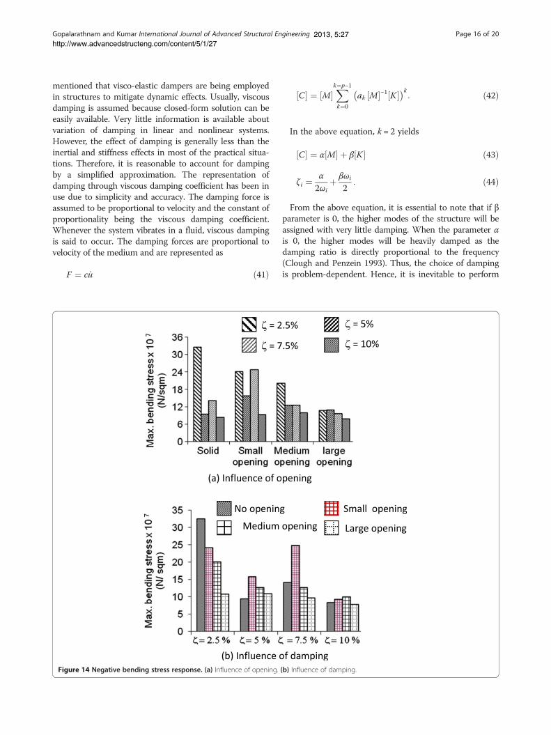
Figure 14 Negative bending stress response. (a) Influence of opening.
C½ � ¼ M½ �Xk¼p−1
k¼0
ak M½ �−1 K½ �� �k: ð42Þ
In the above equation, k = 2 yields
C½ � ¼ α M½ � þ β K½ � ð43Þ
ζ i ¼α
2ωiþ βωi
2: ð44Þ
From the above equation, it is essential to note that if βparameter is 0, the higher modes of the structure will beassigned with very little damping. When the parameter αis 0, the higher modes will be heavily damped as thedamping ratio is directly proportional to the frequency(Clough and Penzein 1993). Thus, the choice of dampingis problem-dependent. Hence, it is inevitable to perform
(b) Influence of damping.

Gopalarathnam and Kumar International Journal of Advanced Structural Engineering Page 17 of 202013, 5:27http://www.advancedstructeng.com/content/5/1/27
modal analysis to determine the different frequencies fordifferent modes. It is also to be noted that the damping iscontrolled by only two parameters. Thus, in the Cauchyseries, one may include as many terms as possible de-pending upon the computational efficiency. The use ofproportional damping is implemented in most of the finiteelement codes. The reason for the use of proportionaldamping is justified by the following explanation. In theequation of motion, the coupling of terms usually occurswhich is reflected in the mass and stiffness matrices. Iner-tia coupling is present when the mass matrix is non-diagonal, and static coupling is present when the stiffnessmatrix is non-diagonal. The coupling of the modes usuallycan be avoided easily in the case of undamped free vibra-tion, but the same is not true for damped vibration.Hence, in order to represent the equation of motion in
Figure 15 Positive shear stress response. (a) Influence of opening. (b) I
uncoupled form, it is suggested to have a damping matrixproportional to the uncoupled mass and stiffness matrices.Thus, Rayleigh's proportional damping has the specific ad-vantage in the sense that the equation of motion can beuncoupled when it is proportional to mass and stiffnessmatrices. Thus, it is proposed to use Rayleigh damping inthis study.
Nonlinear solutionThe numerical procedure for nonlinear analysis employs theiterative procedure to satisfy the equilibrium at the end ofthe load step. Once the convergence of the solution isachieved, the algorithm proceeds to the next step. It is alwaysdesirable to keep the load step very small especially after theonset of nonlinear behavior. The stiffness matrix is updatedat the beginning of each load step. The convergence is said
nfluence of damping.

Gopalarathnam and Kumar International Journal of Advanced Structural Engineering Page 18 of 202013, 5:27http://www.advancedstructeng.com/content/5/1/27
to be achieved if the out-of-balance forces, calculated asunder, is less than the specified tolerance:
ψni ¼ f n−pni ¼ f n−
ZV
BT σni dV < tolerance 0:0025ð Þ: ð45Þ
Results and discussionA reinforced concrete squat square shear wall, 3.6 m ×3.6 m with 0.2-m thick, subjected to EL Centro earth-quake loading over the period of 31.18 s with a peakground acceleration of +0.29 g, as shown in Figure 6,has been considered. For the finite element dynamicanalysis, the entire shear wall is discretized using thenine-node degenerated shell elements of size (0.6 m ×1.2 m). The discretizations of the shear wall for solidand opening cases are shown in Figure 7. The
Figure 16 Negative shear stress response. (a) Influence of opening. (b)
displacement response has been calculated for a periodof 40 s for different damping ratios 2.5%, 5%, 7.5%, and10%, using Newmark β method with constant acceler-ation scheme. In order to investigate the size of openingon structural behavior of shear wall, the results of shearwall with no opening are compared with shear wall withthree different sizes of openings, namely, (a) small open-ing (1.2 m × 1.2 m), (b) medium opening (1.2 m ×2.4 m), and (c) large opening (2.4 m × 2.4 m).For the finite element analysis, the Young's modulus of
elasticity of the concrete is taken as 2.98 × 10¹⁰ N/m2
and Poisson's ratio is taken as 0.17. The undeformedand deformed shapes of the shear walls with and withoutopenings are shown in Figure 7. The displacement andstresses (bending and shear) are grouped into positive (ifthe value is above the horizontal axis of the time history)
Influence of damping.

Gopalarathnam and Kumar International Journal of Advanced Structural Engineering Page 19 of 202013, 5:27http://www.advancedstructeng.com/content/5/1/27
and negative (if the value is below the horizontal axis ofthe time history), and, accordingly, the graphs and tablesare also presented in this study. The deformed shapes(positive and negative deformations) of solid shear walland shear wall with small, medium, and large openingsare qualitatively plotted in Figure 7 in order to highlightthe mode in which the shear wall deforms. The mode ofdeformation of solid shear wall and shear wall with smallopening is almost similar. On the other hand, shear wallwith medium and large openings characterizes the shearmode of deformation. Hence, it is concluded that theracking deformation becomes important in the presenceof medium- as well as large-sized openings. The dis-placement, bending stress, and shear stress time-historyresponses for various opening sizes, viz., no opening,small opening, medium opening, and large opening withdamping ratios ζ = 2.5%, 5%, 7.5%, and 10% are plottedin Figures 8,9,10, respectively.It is obvious from Figure 8 that the increase in the
opening size of shear wall has the strong influence onthe displacement response, which is measured at the topof the shear wall, as evident from various time historiesas well from Tables 3 and 4. From Figure 8, it was ob-served that shear wall with large opening resulted inhuge displacement and the influence of damping has notbeen found to be substantially benefitting in controllingthe response. Moreover, as can be seen in Figure 8, dis-placements were predominantly on the negative side (re-ferred in this study as negative displacement) and thusindicate that the structure is behaving in the one-sidedcyclic fashion characterizing the instability of the struc-ture. The negative displacement values (as observedfrom Table 4) also validate the same. Hence, it is advis-able to avoid large openings in the shear wall for betterstructural response (Figures 11 and 12). On the otherhand, increase in damping has a significant effect on thestructural response.The bending stress responses measured at the bottom
of the shear wall for various opening cases are plotted inFigure 9. It was observed that the bending stresses ofshear wall with no openings, small opening, and mediumopening almost follow the same trend with not much re-versal of stresses which are on the negative side. How-ever, in the case of large opening, the huge reversal ofstresses taking over the entire time history indicates thatthe structure is heavily stressed and such openings areto be avoided in practice. As expected, damping has notresulted in substantial mitigation of the structuraldamage for shear wall with large openings (Figures 13and 14).The shear stress responses of shear wall measured at
the bottom of the shear wall for various opening casesare plotted in Figure 10. The response history of shearstress for shear wall with various opening cases indicates
that for large openings, the shear stresses are found tobe affected by damping ratios to the great extent. Shearstresses were found to be minimal for shear wall with noopening, and damping has a pronounced effect on theshear wall with no opening and with small opening cases(Figures 15 and 16). Since only proportional stiffnessdamping was used throughout the study, higher modeswere considerably damped and hence, the responses(displacement and stresses) decayed toward the end ofthe time step to a greater extent.
ConclusionsIn this paper, the influence of opening sizes on the struc-tural response of squat square shear wall, 3.6 m × 3.6 mand 0.2 m thick subjected to EL Centro earthquake load-ing and applied over the period of 31.18 s, has been inves-tigated for different damping ratios (2.5%, 5%, 7.5%, and10%) using nonlinear finite element analysis. In addition,the following conclusions have been drawn:
1. Racking deformation becomes paramount for shearwalls with medium and large openings.
2. The shear wall with large openings is to be avoidedas it results in instability with one-sided cyclicbehavior.
3. Higher modes have been considerably damped dueto the presence of stiffness proportional damping.
Competing interestsBoth authors declare that they have no competing interests.
Authors’ contributionsBoth authors read and approved the final manuscript.
Authors’ informationG. Muthukumar is a Lecturer in the Department of Civil Engineering, BITSPilani. Prof. Manoj Kumar is an Associate Professor & Head in the Departmentof Civil Engineering, BITS Pilani.
Received: 14 December 2012 Accepted: 25 July 2013Published:
ReferencesAhmad S, Irons BM, Zienkiewicz OC (1970) Analysis of thick and thin shell
structures by curved finite elements. Int J Numerical Methods Eng 2:419–451Archer GC, Whalen TM (2006) Development of rotationally consistent diagonal
mass matrices for plate and beam elements. Comput Methods Appl Eng194:675–689
Baratta A, Corbi O (2010) An approach to masonry structural analysis by the no-tension assumption—part 1: material modeling, theoretical setup, and closedform solutions. ASME Appl Mech Rev 63:1–17
Baratta A, Corbi O (2012) FRP composites retrofitting for protection ofmonumental and ancient constructions. The Open Construction and BuildingTechnology Journal 6:361–367
Baratta A, Corbi I, Corbi O (2008) Stress analysis of masonry structures: arches,walls and vaults, structural analysis of historic construction: preserving safetyand significance. Proceedings of the 6th international conference onstructural analysis of historic construction, SAHC08 1:321–329
Baratta A, Corbi I, Corbi O, Barros RC, Bairrao R (2012) Shaking table experimentalresearches aimed at the protection of structures to dynamic loading. TheOpen Construction and Building Technology Journal 6:355–360
11 Nov 2013

Gopalarathnam and Kumar International Journal of Advanced Structural Engineering Page 20 of 202013, 5:27http://www.advancedstructeng.com/content/5/1/27
Baratta A, Corbi I, Corbi O, Barros RC, Bairrao R (2013) Towards a seismic worstscenario approach for rocking systems: analytical and experimental set-up fordynamic response. Acta Mechanica 224:691–705
Bathe KJ (2006) Finite element procedures. Prentice Hall of India Private Limited,New Delhi
Cedolin L, Crutzen YRJ, Deipoli (1977) Triaxial stress-strain relationships forconcrete. ASCE Journal of the Engineering Mechanics Division 103:423–439
Chen WF (1982) Plasticity in reinforced concrete. McGraw-Hill, New YorkClough RW, Penzein J (1993) Dynamics of structures. McGraw Hill, New YorkCollins MP, Mitchell D (1980) Shear and torsion design of prestressed and non-
prestressed concrete beams. J PCI 25:32–100Corbi I (2013) FRP reinforcement of masonry panels by means of C-fiber strips.
Composites Part B: Engineering 47:348–356Derecho AT, Ghosh SK, Iqbal Q, Fintel M (1979) Strength, stiffness, and ductility
required in reinforced concrete structural walls for earthquake resistance. ACIStruct J 76:875–896
Duggal SK (2007) Earthquake resistant design of structures. Oxford HigherEducation, Oxford University Press, New Delhi
Gasparani G, Trombetti T, Silvestri S, Ricci I, Ivorra Chorro S, Foti D (2013)Preliminary results of a shaking table tests on a 3-storey building realizedwith cast in place sandwich squat concrete walls. In: modern methods andadvances in structural engineering and construction: the seventhinternational structural engineering and construction conference (ISEC-7). ,Honolulu, Hawaii
Huang (1987) Implementation of assumed strain degenerated shell elements.Comput Struct 25:147–155
Huang HC (1989) Static and dynamic analyses of plates and shells: theory,software and applications. Springer, London
Kant T, Kumar S, Singh UP (1994) Shell dynamics with three-dimensionaldegenerate finite elements. Comput Struct 50:135–146
Kim HS, Lee DG (2008) Analysis of shear wall with openings using superelements. Eng Struct 25:981–991
Kuang JS, Ho YB (2008) Seismic behavior and ductility of squat reinforcedconcrete shear walls with nonseismic detailing. ACI Struct J 105:225–231
Lefas ID, Kosovos MD, Ambraseys NN (1990) Behavior of reinforced concretestructural walls, strength, deformation characteristics, and failure mechanism.ACI Struct J 87:23–31
Liu Y, Teng S (2008) Nonlinear analysis of reinforced concrete slabs using non-layered shell element. ASCE, J Struct Eng 134:1092–1100
MacLeod IA (1970) Shear wall-frame interaction- a design aid. EngineeringBulletin, Portland Cement Association (PCA)
Mo YL (1988) Analysis and design of low-rise structural walls under dynamicallyapplied shear forces. ACI Struct J 85:180–189
Mullapudi RT, Charkhchi P, Ayoub AS (2009) Evaluation of behavior of reinforcedconcrete shear walls through finite element analysis. ACI Special Publication265:73–100
Nayal R, Rasheed HA (2006) Tension stiffening model for concrete beamsreinforced with steel and FRP Bars. ASCE, J Mater 146:831–841
Neuenhofer A (2006) Lateral stiffness of shear walls with openings. ASCE, J StructEng 132:1846–1851
Ngo D, Scordelis AC (1967) Finite element analysis of reinforced concrete beams.ACI Struct J 64:152–163
Owen DRG, Hinton E (1980) Finite elements in plasticity. Theory and practice,Pineridge Press Limited, UK
Paknahad M, Noorzaei J, Jaafar MS, Thanoon WA (2007) Analysis of shear wallstructure using optimal membrane triangle element. Finite Element inAnalysis and Design 43:861–869
Paswey SF, Clough RW (1971) Improved numerical integration of thick shell finiteelements. Int J Numerical Methods Eng 3:575–586
Rahimian A (2011) Lateral stiffness of concrete shear walls for tall buildings. ACIStruct J 108:755–765
Rashid YR (1968) Analysis of prestressed concrete pressure vessels. NuclearEngineering Design 7:334–344
Ricci I, Gasparini G, Silvestri S, Trombetti T, Foti D, Ivorra Chooro S, Ivorra ChooroS (2012) Design of a shaking table test on a 3-storey building composed ofcast-in-situ concrete walls. Proceedings of the 15th World Conference onEarthquake Engineering (15WCEE), Lisbon
Rosman R (1964) Approximate analysis of shear walls subjected to lateral loads.ACI Journal 64:717–734
Schwaighofer J (1967) Door openings in shear walls. ACI Journal 64:730–734
Taylor CP, Cote PA, Wallace JW (1988) Design of sender reinforced concrete wallswith openings. ACI Struct J 95:420–433
Teng S, Liu Y, Soh CK (2005) Analysis of concrete slabs using shell element withassumed strain. ACI Struct J 102:515–524
Vecchio FJ, Collins MP (1986) The modified compression field theory forreinforced concrete elements subjected to shear. ACI Journal 83:219–231
Willam K, and Warnke E (1975) Constitutive model for triaxial behavior ofconcrete. Proceedings of the International Association for Bridge andStructural Engineering, 19 Zurich, Switzerland 1-30.
Zareian F, Medina RA (2010) A practical method for proper modeling ofstructural damping in inelastic plane structural systems. Comput Struct88:45–53
Zienkiewicz OC, Taylor RL, Too JM (1971) Reduced integration techniques ingeneral analysis of plates and shells. Int J Numerical Methods Eng 3:575–586
Cite this article as: Gopalarathnam and Kumar: Nonlinear finite elementdynamic analysis of squat shear wall with openings. International Journalof Advanced Structural Engineering .
10.1186/2008-6695-5-27
2013, 5:27
Submit your manuscript to a journal and benefi t from:
7 Convenient online submission
7 Rigorous peer review
7 Immediate publication on acceptance
7 Open access: articles freely available online
7 High visibility within the fi eld
7 Retaining the copyright to your article
Submit your next manuscript at 7 springeropen.com