ORIGINAL PAPER Open Access High-cycle fatigue ...
13
ORIGINAL PAPER Open Access High-cycle fatigue investigations of notched Glare under different stress ratio's in various environments Sunil Bhat 1* and Sockalingam Narayanan 2 Abstract Notched Glare 4A-3/2 laminates, comprising thin 2014-T6 aerospace aluminum alloy sheets alternately bonded with unidirectional E-glass fiber-based composite prepregs, are tested under tensile-tensile fatigue load with different stress ratio’s ranging from 0.1 to 0.5 in ambient, aqueous, and corrosive environments in high-cycle conditions. Fatigue characteristics of the laminates are found to be influenced by the operating environment and the magnitude of stress ratio. Notched plain 2014-T6 aerospace aluminum alloy specimens are also subjected to identical cyclic stress levels as in aluminum alloy layers of the laminates for comparative analysis of their fatigue behavior with those of the laminates. Retarded crack growth rates in the laminates leading to their enhanced fatigue lives and higher cyclic fracture toughness values vis-à-vis plain specimens substantiate fiber bridging effect in the laminates. Keywords: Aqueous environment; Corrosive environment; Fatigue life; Glare; Stress ratio Background Glare, a fiber metal laminate (FML), consists of layers of thin and light aerospace aluminum alloy sheets that are alternately bonded and cured with composite prepregs by heat and pressure, each prepreg is built up of several resin-impregnated unidirectional fiber cloth layers laid in similar or different orientations. Besides offering gain in specific strength, Glare exhibits properties like excellent fatigue and fracture resistance, reasonably good impact strength, and high fire resistance that make it a good substitute for monolithic aluminum alloys especially in aerospace applications. Numerous studies have so far been reported on behavior of various types of FMLs under fatigue loads of constant and variable stress ratios with most of them pertaining to tests conducted in ambient environment only. Notably, in the field of fatigue of FML under load cycles of constant stress ratio in ambient environment, Lin et al. 1991 dis- cussed fatigue behavior in carbon- and aluminum-based FML (Care), followed by Lin and Kao (1995) investigating the effect of fiber bridging and delamination growth (Lin and Kao 1996) on crack propagation in the laminate. Guo and Wu (1998, 1999a, 1999b) presented theoretical and phenomenological models for predicting fatigue crack growth characteristics and bridging stress distribution in FML. Homan (2006) observed that fatigue crack initiation in FML depends upon the magnitude of stress in metal layer. He also investigated the effect of residual stress in fibers and in metal layers over the crack tip. Alderliesten and Homan (2006) discussed fatigue and damage toler- ance issues of Glare in aircraft structures. Suiker and Fleck (2006) presented the relation between fatigue crack growth rate and remote cyclic stress with and without delaminations in a FML. Takamatsu et al. (1999) examined fatigue crack growth in Glare and checked the validity of proposed analytical models. Alderliesten (2007a) studied the propagation of fatigue cracks in aluminum layers of Glare in the presence of delaminations at aluminum-fiber interfaces. He postulated that the stress intensity param- eter at the crack tip is the function of far-field opening stress and closing bridging stress in aluminum layers. An analytical model for fatigue crack propagation and transverse delamination extension using the correlation between growth rate and energy release rate of the delam- ination was proposed by him. The model was implemented * Correspondence: [email protected] 1 School of Civil and Mechanical Engineering, Galgotias University, Greater Noida, UP 203201, India Full list of author information is available at the end of the article © 2014 Bhat and Narayanan licensee Springer. This is an Open Access article distributed under the terms of the Creative Commons Attribution License (http://creativecommons.org/licenses/by/4.0), which permits unrestricted use, distribution, and reproduction in any medium, provided the original work is properly credited. Bhat and Narayanan International Journal of Mechanical and Materials Engineering 2014, 1:3 http://www.springer.com/40712/content/1/1/3
Transcript of ORIGINAL PAPER Open Access High-cycle fatigue ...

Bhat and Narayanan International Journal of Mechanical andMaterials Engineering 2014, 1:3http://www.springer.com/40712/content/1/1/3
ORIGINAL PAPER Open Access
High-cycle fatigue investigations of notchedGlare under different stress ratio's in variousenvironmentsSunil Bhat1* and Sockalingam Narayanan2
Abstract
Notched Glare 4A-3/2 laminates, comprising thin 2014-T6 aerospace aluminum alloy sheets alternately bonded withunidirectional E-glass fiber-based composite prepregs, are tested under tensile-tensile fatigue load with different stressratio’s ranging from 0.1 to 0.5 in ambient, aqueous, and corrosive environments in high-cycle conditions. Fatiguecharacteristics of the laminates are found to be influenced by the operating environment and the magnitude ofstress ratio. Notched plain 2014-T6 aerospace aluminum alloy specimens are also subjected to identical cyclic stresslevels as in aluminum alloy layers of the laminates for comparative analysis of their fatigue behavior with those ofthe laminates. Retarded crack growth rates in the laminates leading to their enhanced fatigue lives and highercyclic fracture toughness values vis-à-vis plain specimens substantiate fiber bridging effect in the laminates.
Keywords: Aqueous environment; Corrosive environment; Fatigue life; Glare; Stress ratio
BackgroundGlare, a fiber metal laminate (FML), consists of layers ofthin and light aerospace aluminum alloy sheets that arealternately bonded and cured with composite prepregsby heat and pressure, each prepreg is built up of severalresin-impregnated unidirectional fiber cloth layers laidin similar or different orientations. Besides offering gain inspecific strength, Glare exhibits properties like excellentfatigue and fracture resistance, reasonably good impactstrength, and high fire resistance that make it a goodsubstitute for monolithic aluminum alloys especially inaerospace applications.Numerous studies have so far been reported on behavior
of various types of FMLs under fatigue loads of constantand variable stress ratios with most of them pertaining totests conducted in ambient environment only. Notably, inthe field of fatigue of FML under load cycles of constantstress ratio in ambient environment, Lin et al. 1991 dis-cussed fatigue behavior in carbon- and aluminum-basedFML (Care), followed by Lin and Kao (1995) investigatingthe effect of fiber bridging and delamination growth (Lin
* Correspondence: [email protected] of Civil and Mechanical Engineering, Galgotias University, GreaterNoida, UP 203201, IndiaFull list of author information is available at the end of the article
© 2014 Bhat and Narayanan licensee Springer.Commons Attribution License (http://creativecoreproduction in any medium, provided the orig
and Kao 1996) on crack propagation in the laminate. Guoand Wu (1998, 1999a, 1999b) presented theoretical andphenomenological models for predicting fatigue crackgrowth characteristics and bridging stress distribution inFML. Homan (2006) observed that fatigue crack initiationin FML depends upon the magnitude of stress in metallayer. He also investigated the effect of residual stress infibers and in metal layers over the crack tip. Alderliestenand Homan (2006) discussed fatigue and damage toler-ance issues of Glare in aircraft structures. Suiker and Fleck(2006) presented the relation between fatigue crackgrowth rate and remote cyclic stress with and withoutdelaminations in a FML. Takamatsu et al. (1999) examinedfatigue crack growth in Glare and checked the validity ofproposed analytical models. Alderliesten (2007a) studiedthe propagation of fatigue cracks in aluminum layers ofGlare in the presence of delaminations at aluminum-fiberinterfaces. He postulated that the stress intensity param-eter at the crack tip is the function of far-field openingstress and closing bridging stress in aluminum layers.An analytical model for fatigue crack propagation andtransverse delamination extension using the correlationbetween growth rate and energy release rate of the delam-ination was proposed by him. The model was implemented
This is an Open Access article distributed under the terms of the Creativemmons.org/licenses/by/4.0), which permits unrestricted use, distribution, andinal work is properly credited.

Bhat and Narayanan International Journal of Mechanical and Materials Engineering 2014, 1:3 Page 2 of 13http://www.springer.com/40712/content/1/1/3
in a numerical program, and the results were validated withthe range of experimental data. Good agreement betweencrack growth rates, crack opening contours, and delamin-ation shapes was obtained. Alderliesten (2007b) reviewedphenomenological, analytical, and finite element models forfatigue crack propagation prediction in Glare. Chang andYang (2008) examined fatigue crack growth in Glare bymodulating the stress intensity parameter with a bridgingfactor and obtained the S-N curve based on the initiationand growth life of the crack. Paris law was employed topredict crack growth rates. Shim et al. (2003) adopted amechanistic approach to predict fatigue crack growthin Glare with the help of Paris law. Kawai and Kato(2006) examined the effects of stress ratio on off-axisfatigue behavior of Glare. They tested the coupons underdifferent stress ratios of 0.1, 0.4 and −0.2. A fatiguedamage model to account for the effect of stress ratioon crack characteristics was developed. Likewise, in thefield of fatigue of FML under load cycles of variable stressratios in ambient environment, Kawai and Hachinobe(2002) examined the effects of change in amplitude of loadduring the test on off-axis fatigue strength of Glare.The results of two-stress level cycles were comparedwith those of constant amplitude cycles. Khan et al.(2010) predicted the fatigue crack growth in Glarewhen subjected to variable amplitude cycles by usingmodified Wheeler model based on Irwin's crack tipplasticity correction and validated the theoretical resultswith the help of experiments.Limited work is reported on fatigue behavior of FMLs
under different stress ratios in other possible operatingenvironments although successful attempts have beenmade to evaluate their properties and performance in hightemperature. For instance, Rans et al. (2011) presented ananalytical model to predict fatigue crack growth rate inFML operating in high temperature. The model wasvalidated with experimental data collected in ambient
Figure 1 Glare laminate.
conditions. da Costa et al. (2012) investigated the influ-ence of thermal shock cycles on mechanical propertiesof FML. FML coupons, under cyclic load, were exposedto fast temperature transition from −50°C to +80°C.Tensile and inter-laminar shear strengths of couponswere measured after 1,000 and 2,000 cycles. No significantchanges were found in micro-structure and mechanicalproperties of exposed coupons vis-à-vis the unexposedones. This paper presents experimental results of seriesof notched Glare laminates subjected to tensile-tensilefatigue cycles with different stress ratios ranging from0.1 to 0.5 in aqueous and corrosive environments. Thelaminates are tested in ambient environment as well.The stress ratio is kept constant during each test whilefulfilling high-cycle conditions in the laminates. Notchedplain aerospace aluminum alloy specimens are also testedunder identical cyclic stress levels as those in aluminumalloy layers of the laminates for comparative analysisbetween them and the laminates.
Glare detailsRefer to Figure 1. Glare in the present work comprisesthree thin layers of 2014-T6 aerospace aluminum alloyand two prepregs, each prepreg is built up of threecomposite layers in the sequence c0-c90-c0. A compositelayer consists of 4-mil or 0.1-mm thick unidirectionalE-glass fiber cloth of grammage 110 gsm coated withCY205 epoxy resin (HY905 as hardener) on both sides.The volume fractions of fiber and resin in a compositelayer are 0.522 and 0.478. Composite c0 has fibers laidin the y direction, i.e., along the direction of rolling ofaluminum alloy, whereas composite c90 has fibers ori-ented in the x direction, i.e., transverse to the rollingdirection of aluminum alloy. The grade of laminate withchosen configuration is Glare 4A-3/2 (4A denoting 0-90-0orientation of composites in prepreg, and 3/2 representingnumber of aluminum alloy layers and prepregs in the

Bhat and Narayanan International Journal of Mechanical and Materials Engineering 2014, 1:3 Page 3 of 13http://www.springer.com/40712/content/1/1/3
laminate). The properties of the constituent materials(Callister 2004) are displayed in Table 1. The standard/desired dimensions of the laminate and its ingredientsare the following: l = 200 mm, w = 50 mm, d = 2.346 mm,tal = 0.4 mm, tr = 0.0455 mm, tf = 0.1 mm, tc0 = 0.191 mm,and tc90 = 0.191 mm.The laminate is loaded in the y direction because it
demonstrates good strength and fatigue properties dueto more number of c0 composites in prepregs. Since thematerial layers in the laminate are elastically unidentical,stress redistribution takes place in them under the ac-tion of applied stress in order to maintain same strain inall the layers. In addition, variable residual stresses aregenerated in the materials, during curing of the laminate,due to their different stiffness and coefficients of thermalexpansions. The coefficients of thermal expansion of thelaminate in longitudinal (y) direction, αll, and in transverse(x) direction, αtl, are found to be equal to 19.40 × 10− 6 C−1
and 19.77 × 10− 6 C−1, respectively, with the help of elem-entary formulations related to composites and laminates(Bhat and Narayanan 2014). Refer to Appendix 1. Thesecoefficients are required to estimate the residual strain ineach material layer that when superimposed with thestrain developing in the laminate under maximum (max)applied tensile stress value in the fatigue cycle, σy,applied,max
results in maximum induced stress value in material layer,m, as σy,induced,m,max. σy,induced,m,max therefore equals thesum of redistributed stress, σy,ds,m.,max and residualstress, σy,rs,m. Standard stress-strain constitutive equationsof individual materials under plane stress condition, dueto their small thickness, are employed to obtain theirstiffness in the x-y plane. Classical theory is used todetermine the stiffness of the laminate. Both redistributedand residual stresses in materials along the z directionare considered to be negligible. Stress state around cracktips in aluminum alloy layers further deviates from
Table 1 Properties of materials used in Glare
Property Aluminum2014-T6 alloy (al)
E-glassfiber (f)
Epoxyresin (r)
Modulus of elasticity (E), MPa 72,000.0 71,000.0 3,500.0
Shear modulus (μ), MPa 27,060.0 29,700.0 1,250.0
Poisson's ratio (υ) 0.33 0.22* 0.33
Yield strength (Y), MPa 372.0 - -
Ultimate tensile strength, MPa 415.0 3,450.0 60
Percent elongation 8.0 4.8 4.0
Coefficient of thermalexpansion (α), C−1
23 × 10− 6 5.0 × 10− 6 57.5 × 10− 6
Density, g/cc 2.71 2.45 1.54
Plane strain fracture toughness(KIC), MPa
ffiffiffiffim
p 14.0 to 20.0 4.0 to 5.0 0.5 to 0.7
The asterisk denotes a major value.
induced stress due to bridging of load over crackstowards stronger fibers, commonly referred to as fiberbridging. Fiber bridging generates closing compressivestress in aluminum alloy layers that diminishes tensilestress fields around crack tips thereby shielding them.
Theoretical aspectsSince the cracks nucleate and grow in soft aluminumalloy layers of the laminate, different forms of stressintensity parameters are found in the laminate by usingstress values in aluminum alloy layers. As discussed in the‘Glare details’ section, the redistribution of applied stressand presence of residual stress in aluminum alloy layerscause the induced stress intensity parameter, Kinduced, todiffer from the applied value, Kapplied. Further, due to fiberbridging in the laminate, the crack tip stress intensityparameter, Ktip, also deviates from Kinduced. Ktip is foundby employing numerical or theoretical methodologiesdescribed elsewhere (Bhat and Narayanan 2014, pp.157–160). However, in the present work, only Kapplied
and Kinduced are used as characterizing parameters that,with the help of available experimental data, are foundto be adequate to quantify the effect of fiber bridging inthe laminates by comparing their fatigue behavior withthat of plain aluminum alloy specimens.The following conventional equations are employed
to obtain various forms of cyclic stress intensity param-eter, ΔK, in laminate with edge crack of length, c, inaluminum layer under plane stress condition in high-cycle regime where principles of linear elastic fracturemechanics (LEFM) are valid:
(i) Using applied stress value in the fatigue cycle asfollows:
ΔK applied ¼ σy;applied;max� 1−Rð Þh i
� ffiffiffiffiffiπc
p � CF� U ;
ð1Þ
where U is crack closure ratio and stress ratio, andR ¼ σy;applied;min
σy;applied;max. Configuration factor, CF, of an edge
crack in rectangular body is empirically given byCF ¼ 1:12−0:23 c
w þ 10:55 cw
� �2−21:72 cw
� �3 þ 30:39 cw
� �4h i(Kumar 2009). The expression is used in the presentwork, albeit with slight inaccuracy, even when theratio c
w exceeds 0.7.At laminate fracture when c = c⊗,
ΔK applied ¼ ΔKC;applied ð2Þ
where c⊗ is the critical crack length

Bhat and Narayanan International Journal of Mechanical and Materials Engineering 2014, 1:3 Page 4 of 13http://www.springer.com/40712/content/1/1/3
(ii) Refer to Figure 2a). Using induced stress value inaluminum alloy layer as follows:
ΔK induced ¼ σy;ds;al;max þ�
σy;rs;al� �
− R�ð σy;ds;al;max
þ σy;rs;alÞ� �ffiffiffiffiffiπc
p � CF� U
where σy,ds,al,max and σy,rs,al are redistributed and residualstress in load line, y, direction in aluminum alloy layer.Since σy,rs,al is tensile (+ve) that makes the term (R × σy,ds,al,max + σy,rs,al) greater than zero (tensile), the effect ofresidual stress is nullified. ΔKinduced reduces to
ΔK induced ¼ σy;ds;al;max 1−Rð Þ� �� ffiffiffiffiffiπc
p � CF� U ð4ÞΔK induced ¼ ΔKC;induced ð5Þ
whenc ¼ c⊗
(iii) Refer to Figure 2b. The value of ΔK in plainaluminum alloy specimen (P) is obtained from theapplied stress value only due to the absence of loadredistribution and residual stress in the specimen.Since tensile residual stress in aluminum layers ofthe laminate does not influence its fatigue properties,
a)
Figure 2 Details of load over (a) aluminum alloy layer of laminate and
maximum stress, σy,applied,max, in fatigue cycles appliedover plain specimens is kept equal to σy,ds,al,max tosimulate identical fatigue load in plain specimens asthat in aluminum alloy layers of the laminates. ΔK inplain specimen is written as follows:
ΔKP ¼ σy;applied;max � 1−Rð Þh i
� ffiffiffiffiffiπc
p � CF
� U
¼ σy;ds;al;max � 1−Rð Þ� � ffiffiffiffiffiπc
p � CF� Uh
ð6Þ
ΔKP ¼ ΔKC;al ð7Þwhen
c ¼ c⊗
U of aluminum alloy in all the above equations istaken as 0.5 + 0.4R (Elber 1976).
Experimental methodTwo-millimeter thick 2014-T6 aluminum alloy sheetswere cold rolled to reduce their thickness to acceptablelevel that was followed by their suitable heat treatmentto restore the T6 state of the aluminum alloy. Prepregswere manually prepared and stored in controlled envir-onment prior to use. At the time of laminate fabrication,an assembly of three aluminum alloy sheets alternatelyreinforced with two prepregs was loaded in a hydraulic
b)
(b) plain aluminum alloy specimen.

Bhat and Narayanan International Journal of Mechanical and Materials Engineering 2014, 1:3 Page 5 of 13http://www.springer.com/40712/content/1/1/3
press preheated to 90°C. A pressure of 10 bar was grad-ually applied over the assembly. The temperature wasraised to 160°C, and the assembly was cured at thattemperature for 3 h. After curing, the press was cooledto room temperature followed by the release of pressure.The laminate assembly was taken out from the pressand visually inspected for defects. The thickness data ofall the laminates were recorded. The achieved/mea-sured dimensional range of the laminate was as follows:tal = 0.35 to 0.58 mm, d = 2.2 to 2.9 mm, l = 200 to202 mm, and w = 50.35 to 51.35 mm. Deviations fromthe desired values provided in the ‘Glare details’ section,especially in laminate thickness, were attributed to (i)difficulty in maintaining precise control over thicknessof aluminum alloy sheets during rolling, (ii) manualapplication of resin over fiber cloth during the prepar-ation of prepregs, and (iii) effect of high temperatureand bonding pressure on the dimensions of the materiallayers during curing of the laminate. The dimensionaldifference between the laminates however has not beenincluded in the computations at Appendix 1 that arebased on standard dimensions.Before proceeding with fatigue tests, standard speci-
mens were machined out from laminates for tensile,flexural, and shear strength measurement to check themechanical properties of the laminates. Several speci-mens were used in each test to obtain reliable results.The results, provided in Table 2, displayed goodconsistency, thereby validating the test data and alsothe fabrication procedure of laminates. Optical mi-croscopy was undertaken on external aluminum alloylayers of the laminate to check the effects of high cur-ing temperature on their micro-structure. One percentHF solution was used as an etchant. The micro-structure confirmed fine dispersion of Cu-Al2 andAl-Si particles in the matrix of the aluminum solidsolution without development of new detrimentalproducts.Refer to Figure 3. Glare laminates, with starter Mode I
edge notches of 1.5-mm size machined across all thematerial layers, held at opposite ends of a hydraulic testrig with gripping pressure of 5 MPa were subjected totensile-tensile fatigue cycles at 25 cycles/s in the y direc-tion until they fractured under the following load andenvironmental conditions:
Table 2 Mechanical properties of Glare
Property Specimen 1 Specimen
Yield strength (MPa) 269.7 273.05
Ultimate tensile strength (MPa) 360.3 365.13
Flexural strength (MPa) 728.8 763.0
Shear strength (MPa) 37.79 40.04
(i) σy,applied,max value of 75 MPa in fatigue cycle toensure controlled crack growth rates for effectivemeasurement and recording purpose
(ii) Stress ratio, R, of 0.1, 0.3, and 0.5 (all +ve). Theratio was kept constant during each test to maintainconstant amplitude of load
(iii)Test environments namely ambient (A), aqueous(M), and corrosive (S)
Aqueous and corrosive environments were simulatedby immersing the laminates in respective fluids, i.e., plainwater (M) and salt + water solution (S) for sufficientperiod of time followed by spraying fluids over the lami-nates during fatigue tests. As expected, fatigue cracksnucleated in soft aluminum alloy layers, but not in strongfibers of prepregs in all the test conditions. Refer toFigure 4. The cracks were found to grow simultaneouslyin all three aluminum alloy layers of some laminates (caseI, Figure 4a), whereas in only one external aluminum alloylayer of the remaining laminates (case II, Figure 4b). Thisphenomenon, in general, did not exhibit any specificcorrelation with the operational parameters except thedevelopment of case I in aqueous environment at allthe values of R and the development of case II in ambientenvironment at R of 0.3. Delaminations did not develop inboth cases as no interfacial crack growth was observed inthe transverse direction at aluminum-fiber interfaces. Thiswas also confirmed by fractography (SEM) images ofthe fatigue surfaces of aluminum alloy layers of fracturedlaminates; few such images are displayed in highly magni-fied form in Figure 5. The size, b, of the interfacial crackwas negligible in comparison with the size, c, of mode Icracks, thereby supporting the absence of delaminations.Crack lengths, c, were measured. Corresponding number
of cycles, N, was recorded. Crack growth rate, dcdN , at each
crack length was computed. Values of c⊗ and total cycles,N⊗, consumed in crack initiation at the notch tip and sub-sequent propagation until fracture of each laminate werenoted, with N⊗ being the measure of fatigue life. dc
dN valueswere also obtained in the notched plain 2014-T6 aerospacealuminum alloy specimens with dimensions nearly similaras those of the laminates for comparative analysis of theirfatigue behavior with those of the laminates. These speci-mens were subjected to tensile-tensile fatigue cycles withR of 0.1 in ambient environment alone. As discussed
2 Specimen 3 Mean Standard deviation
277.28 273.34 3.79
370.62 365.35 5.163
730.1 740.63 19.381
42.74 40.19 2.478

Figure 3 Fatigue test arrangement. (a) Starter notch in laminate, (b) simulation of moist and corrosive environments during test, (c) fatiguecrack in laminate, and (d) fractured laminate.
Bhat and Narayanan International Journal of Mechanical and Materials Engineering 2014, 1:3 Page 6 of 13http://www.springer.com/40712/content/1/1/3
in the ‘Theoretical aspects’ section, the maximumstress in fatigue cycles applied over such specimens wasfixed at 97.45 MPa. Refer to Appendix 1. The value ofredistributed stress, σy,ds,al,max, in aluminum alloy layers ofthe laminate when it experiences peak applied stress of75 MPa during the fatigue cycle is 97.45 MPa.
Results and discussionThe values of σy;induced;al;max
Y alin the laminates and σy;ds;al;max
Y alin
the plain aluminum alloy specimens are less than 0.5 that
Figure 4 Schematic of fatigue crack growth in (a) case I and (b) case
indicate LEFM regime and high-cycle fatigue condition(Yal representing yield strength of aluminum alloy). Thevalue around crack tips in the laminates further dropswith the onset of fiber bridging, thereby promotinghigh-cycle condition. Refer to Table 3. High values ofN⊗ recorded in the laminates and in plain specimensalso support high-cycle conditions. So, the use of
parameter ΔK is valid. Fulfillment of equations tal < 2:5
ΔK induced2Y al
� �2in laminates and d < 2:5 ΔKP
2Y al
� �2in plain
II laminates.

Figure 5 Fractographs of fatigue surfaces of aluminum alloy layers in Glare. a) Fractograph 1) b) Fractograph 2).
Bhat and Narayanan International Journal of Mechanical and Materials Engineering 2014, 1:3 Page 7 of 13http://www.springer.com/40712/content/1/1/3
specimens at nearly all crack lengths confirms planestress condition from fatigue point of view. Hence, theuse of parameter ΔKC is justified. All forms of ΔK arecomputed at increasing crack lengths using Equations 1to 7. The results of the laminates in all test environmentsare as follows:
Case I laminatesThe data of case I laminates under different Rs arepresented in the form of series 1 to 9: series 1 to 4 inambient environment, series 5 to 7 in aqueous envir-onment, and series 8 to 9 in corrosive environment.
Table 3 Dimensional data and fatigue results of Glarelaminates and plain aluminum alloy specimens
Series w (mm) d (mm) Environment R c⊗ (mm) N⊗ (cycles)
Glare laminates
Case I
1 50.55 2.85 A 0.1 28 46,328
2 50.7 2.5 A 0.5 34 115,000
3 50.8 2.2 A 0.5 35 126,270
4 50.55 2.55 A 0.5 15 58,725
5 50.5 2.6 M 0.1 34 29,163
6 50.7 2.48 M 0.3 35 22,473
7 51.35 2.35 M 0.5 30 193,503
8 51.1 2.9 S 0.1 13 5,157
9 50.35 2.6 S 0.3 9 8,671
Case II
1 50.4 2.3 A 0.1 32 63,697
2 50.5 2.55 S 0.1 30 52,476
3 50.45 2.6 A 0.3 40 66,219
4 50.4 2.6 A 0.3 45 81,212
5 50.45 2.2 S 0.5 26 48,717
Plain aluminum 2014-T6 alloy specimens
P1 36.3 1.6 A 0.1 15 16,575
P2 50.9 1.55 A 0.1 20 37,225
Types of test environments: A, ambient; M, aqueous; S, corrosive.
Refer to Figure 6a. The value on the vertical axis ofdata point at the extreme right in each curve repre-sents N⊗. (i) In ambient environment, the number ofcycles, N, needed for crack growth increases with theincrease in R. N⊗ too increases with R. (ii) In aqueousenvironment, N shows mixed results with increase inR. At lower R, N and N⊗ decrease with the increase inR, whereas at higher R, N and N⊗ increase with theincrease in R. (iii) In corrosive environment, N and N⊗
increase slightly with the increase in R.Refer Figure 6b,c,d. (i) In ambient environment, increase
in stress ratio, R, dips dcdN unlike in homogeneous and some
composite materials where increase in R reduces crackclosure causing increase in dc
dN . This is attributed to sub-stantial influence of reduction in applied and inducedvalues of cyclic stress intensity parameter due to increasein R in comparison with corresponding reduction in crackclosure. Moreover, closure effects in the laminates donot appear to be dominant due to crack tip shieldingcaused by fiber bridging that results in minimal cracktip plasticity. Maximum dc
dN at R of 0.1 is 0.015 mm/cycle, while the corresponding value at R of 0.5 is0.00347 mm/cycle. Using the applied value, the max-imum fracture toughness value of laminate, ΔKC,applied,is 49.74 MPa
ffiffiffiffim
pat R of 0.5 (U = 0.7). Likewise, using
induced stress value in aluminum layers, ΔKC,induced is64.6 MPa
ffiffiffiffim
p. (ii) In aqueous environment, increase in
R again dips dcdN. Maximum dc
dN at R of 0.1 is 0.028 mm/cycle,while the corresponding value at R of 0.5 is 0.00245 mm/cycle. In comparison with ambient environment at samevalues of R and stress intensity parameter, dc
dN values arehigher at lower R and lower at higher R. Laminate frac-ture toughness values also show an upward trend. Themaximum value of ΔKC,applied is 63.9 MPa
ffiffiffiffim
pat R of 0.1
(U = 0.54). The corresponding induced value is 83.0 MPaffiffiffiffim
p. (iii) In corrosive (salt) environment, increase in R
augments dcdN . The maximum dc
dN at R of 0.1 is 0.01 mm/cycle, while the corresponding value at R of 0.3 is0.02 mm/cycle. In comparison with ambient environment

a)
b)
c)
d)
Figure 6 Plots of case I laminates. (a) Crack length vs. number of cycles. (b) Crack length vs. crack growth rate. (c) Cyclic applied stress intensityparameter vs. crack growth rate. (d) Cyclic induced stress intensity parameter vs. crack growth rate.
Bhat and Narayanan International Journal of Mechanical and Materials Engineering 2014, 1:3 Page 8 of 13http://www.springer.com/40712/content/1/1/3
at same values of R and stress intensity parameter, dcdN
values are more at both lower and higher values of R. Incomparison with aqueous environment at same values ofR and stress intensity parameter, dc
dN values are also moreat both lower and higher values of R. Laminate fracturetoughness values are much less than those in ambient andaqueous environments. The maximum value of ΔKC,applied
is 11.15 MPaffiffiffiffim
pat R of 0.1 (U = 0.54). The correspond-
ing induced value is 14.48 MPaffiffiffiffim
p.
Case II laminatesThe data of case II laminates under different Rs are pre-sented in the form of series 1 to 5: series 1, 3, and 4 inambient environment, and series 2 and 5 in corrosive en-vironment. Refer to Figure 7a. (i) In ambient environment,N and N⊗ increase with increase in R. (ii) In corrosiveenvironment, N and N⊗ decrease with increase in R.Refer to Figure 7b,c,d. (i) In ambient environment, in-
crease in R dips dcdN , although the effect is not as high as in
case I laminates. The maximum dcdN at R of 0.1 is 0.01 mm/
cycle, while the corresponding value at R of 0.3 is0.0075 mm/cycle. The maximum value of ΔKC,applied is161.2 MPa
ffiffiffiffim
pat R of 0.3 (U = 0.62). The maximum in-
duced value, ΔKC,induced, even reaches up to 209.4 MPaffiffiffiffim
p.
In comparison with case I laminates in the same environ-ment, the maximum laminate fracture toughness values arehigher, and the maximum dc
dN values are of nearly similar
magnitudes. (ii) In aqueous environment, crack did notgrow in one but in all the aluminum layers, which is alreadydiscussed in case I laminate. (iii) In corrosive (salt) environ-ment, the increase in R augments dc
dN . The maximum dcdN at
R of 0.1 is 0.0028 mm/cycle, while the corresponding valueat R of 0.5 is 0.0154 mm/cycle. In comparison with theambient environment at same values of R and stress inten-sity parameter, dc
dN values are smaller at lower R but more athigher R. The data for comparison with aqueous environ-ment are not available. The maximum value of ΔKC,applied
is 44.07 MPaffiffiffiffim
pat R of 0.1 (U = 0.54). The corresponding
induced value is 57.26 MPaffiffiffiffim
p. In comparison with case I
laminate in same environment, the maximum fracturetoughness values are higher, and the maximum dc
dN valuesare lesser.
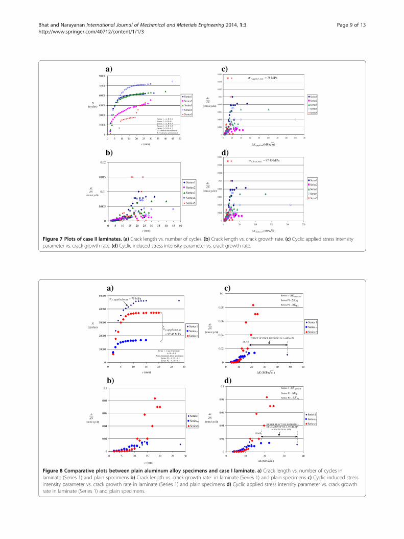
Comparison between performance of laminates and plainaluminum alloy specimensRefer to Figure 8a,b and Table 3. Since plain aluminumalloy specimens, series P1 and P2, exhibited crack growthon both their sides, their behavior is compared with series1 of case I laminates that was tested under similar condi-tions, i.e., R of 0.1 in ambient environment. The values ofN and N⊗ in the plain specimens are lesser than those incase I laminate. Opposite holds good for dc
dN.The values of ΔKC,al are obtained as 22.40 MPa
ffiffiffiffim
pin
series P1 and 24.50 MPaffiffiffiffim
pin series P2. Deviation in
a)
b)
c)
d)
Figure 7 Plots of case II laminates. (a) Crack length vs. number of cycles. (b) Crack length vs. crack growth rate. (c) Cyclic applied stress intensityparameter vs. crack growth rate. (d) Cyclic induced stress intensity parameter vs. crack growth rate.
a) c)
b) d)
Figure 8 Comparative plots between plain aluminum alloy specimens and case I laminate. a) Crack length vs. number of cycles inlaminate (Series 1) and plain specimens b) Crack length vs. crack growth rate in laminate (Series 1) and plain specimens c) Cyclic induced stressintensity parameter vs. crack growth rate in laminate (Series 1) and plain specimens d) Cyclic applied stress intensity parameter vs. crack growthrate in laminate (Series 1) and plain specimens.
Bhat and Narayanan International Journal of Mechanical and Materials Engineering 2014, 1:3 Page 9 of 13http://www.springer.com/40712/content/1/1/3

Bhat and Narayanan International Journal of Mechanical and Materials Engineering 2014, 1:3 Page 10 of 13http://www.springer.com/40712/content/1/1/3
values is due to slight difference in thickness of specimensin stated series. Cyclic plane strain fracture toughness ofplain specimens, ΔKIC,al, is found by using well-knownexpression (Irwin 1967) that links plane stress and planestrain values as follows:
ΔKC;al ¼ ΔK IC;al 1þ 1:4
d2
ΔK IC;al
Y al
4" #1
2=
ð8Þ
As the thickness of plain specimens is different than thatof series 1 laminate, their ΔKC,al,∗ values corresponding tothe thickness of the laminate, i.e., 2.85 mm, is determinedby using Equation 8. ΔKIC,al, is first obtained using ΔKC,al
with original specimen thickness that is followed by re-computation of ΔKC,al,∗ from the same equation withchanged specimen thickness. The results of the plainaluminum alloy specimens are consolidated as follows:Series P1: specimen thickness, d = 1.6 mm, w = 36.3 mm,
c⊗ = 15 mm, ΔKC;al ¼ 22:40 MPaffiffiffiffim
p(CF = 2.179);
ΔK IC;al ¼ 14:69 MPaffiffiffiffim
p; for thickness of 2.85 mm,
ΔKC;al;� ¼ 17:49 MPaffiffiffiffim
p.
Series P2: Specimen thickness, d = 1.55 mm, w = 50.9 mm,c⊗ = 20 mm ΔKC;al ¼ 24:50 MPa
ffiffiffiffim
p(CF = 2.065);
ΔK IC;al ¼ 15:17 MPaffiffiffiffim
p; for thickness of 2.85 mm,
ΔKC;al;� ¼ 18:43 MPaffiffiffiffim
p.
Quasi-static KIC,al values of plain specimens, equal toΔK IC;al
0:9 , are 16.32 MPaffiffiffiffim
p(series P1) and 16.85 MPa
ffiffiffiffim
p(series P2) that lie within the expected range of planestrain fracture toughness of 2014-T6 aluminum alloyavailable in Table 1. This authenticates the quality ofaluminum alloy used as well as the accuracy of fatiguetest equipment.Refer to Figure 8c. To quantify the effect of fiber bridg-
ing in laminate vis-à-vis plain aluminum alloy specimen,induced cyclic stress intensity parameter values in thelaminate are employed for comparison. ΔKC,induced ofseries 1 laminate is 47.72 MPa
ffiffiffiffim
p. On the other hand, the
maximum value of ΔKC,al,∗ in the plain specimen (seriesP2) is 18.43 MPa
ffiffiffiffim
pwhich is much less than that of
series 1 laminate. The values of N⊗ in plain specimens are16,575 cycles (series P1) and 37,225 cycles (series P2),whereas it is 46,328 cycles for series 1 laminate. At othervalues of R in ambient environment, the values of N⊗
of the laminates are much more than those of the plainspecimens. The maximum dc
dN of the plain specimens are0.013 mm/cycle (series P1) and 0.083 mm/cycle (seriesP2) which are nearly identical or higher than that of0.015 mm/cycle of the series 1 laminate. The values of c⊗in the plain specimens are 15 mm (series P1) and 20 mm(series P2) that are also less than 28 mm in series 1 lamin-ate. These findings convincingly confirm the phenomenonof fiber bridging in the laminate that shields the crack tips
in its aluminum alloy layers, thereby retarding fatiguecrack growth rates and increasing critical crack lengthsleading to enhanced fatigue life and cyclic fracture tough-ness values of the laminate in comparison with plainaluminum alloy specimens.Refer to Figure 8d. To compare the fracture potential
of Glare laminate vis-à-vis plain aluminum alloy speci-men from commercial point of view, applied cyclic stressintensity parameter values in the laminate are used inorder to disregard the effects of stress redistribution andresidual stress in the laminate that are missing in theplain specimens. The maximum ΔKC,applied value ofseries 1 laminate is 36.75 MPa
ffiffiffiffim
pwhich too is higher
than the maximum ΔKC,al,∗ of 18.43 MPaffiffiffiffim
pin plain
specimens, justifiably assuming that the ΔKP data of theplain specimens do not change significantly under fatiguecycles with peak stress value of 75 MPa instead of97.45 MPa. This observation substantiates higher fatigueand fracture potential of the laminate vis-à-vis plainaluminum alloy specimens under similar load and envir-onmental conditions.
ConclusionsNotched Glare 4A-3/2 laminates comprising three thin2014-T6 aerospace aluminum alloy layers alternatelybonded and cured with two epoxy resin-impregnated E-glass fiber-based composite prepregs are tested underconstant amplitude tensile-tensile fatigue cycles withpositive stress ratios, R, of 0.1, 0.3, and 0.5 in ambient,aqueous, and corrosive (salt) environments. The maximumstress in the applied fatigue cycle is fixed at 75 MPa. Thecracks grow simultaneously in all the aluminum layersof some laminates (case I), while in only one externalaluminum layer of the remaining laminates (case II). Nointerfacial crack growth and delamination is observed ataluminum fiber interfaces in both cases. Notched plain2014-T6 aerospace aluminum alloy specimens are alsotested at R of 0.1 in ambient environment under identicalstress levels as in aluminum alloy layer of laminates forcomparative analysis of their fatigue behavior with thoseof the laminates. Following generalized conclusions aredrawn from the reported results:
(i) Increase in R dips fatigue crack growth rate, dcdN , in
the laminates under ambient and aqueousenvironments, whereas it augments dc
dN in corrosive(salt) environment. The trends hold good in bothcase I and case II laminates.
(ii) Fatigue lives of laminates, N⊗, change withenvironment. They are higher in ambient andaqueous environments and least in corrosiveenvironment. Increase in R enhances the fatigue lifein both ambient and aqueous environments in case

Bhat and Narayanan International Journal of Mechanical and Materials Engineering 2014, 1:3 Page 11 of 13http://www.springer.com/40712/content/1/1/3
I and in ambient environment in case II laminatesdue to drop in dc
dN . In corrosive environment, N⊗ incase I laminates is found to increase with increasein R which is contrary to expectations since dc
dNincreases with increase in R in such anenvironment. This aberration is attributed to highercrack initiation life and reduced propagation life athigher R. In case II laminates under similarenvironment, the results are in line with theexpectations. Also, at same R in case I laminates,fatigue life in ambient environment is higher thanin aqueous environment at lower R and vice versaat higher R. This is due to higher dc
dN values at lowerR and lesser dc
dN values at higher R in aqueousenvironment in comparison with that in ambientenvironment. Fatigue life in ambient environment ishigher than that in corrosive environment at sameR in both case I and case II laminates.
(iii) Cyclic fracture toughness values of the laminates alsochange with environment. They are higher in aqueousand ambient environments and least in corrosiveenvironment in both case I and case II laminates. Incase I laminate, the values in ambient environment, ingeneral, increase with increase in R. In aqueousenvironment, the values are higher at lower R andlower at higher R. In corrosive environment, the valuestend to drop with increase in R. Trends in case IIlaminates under ambient and corrosive environmentsare similar to as stated for case I laminates.
(iv) From fatigue and fracture point of view, thelaminates can be employed in aqueous environmentsprovided that persistent or excessive exposure towater does not degrade the quality of adhesive/resinbetween the aluminum alloy and fiber layers leadingto their separation or reduction of the strength offibers resulting in overall property degradation of thelaminate. This aspect needs to be investigatedseparately. But fatigue and fracture behavior of thelaminates clearly deteriorates in corrosiveconditions, although the results in case II are betterthan those in case I. Such observations go againstthe use of laminates in corrosive environment.
(v) Fatigue lives and cyclic fracture toughness oflaminates are convincingly more than those of plainaluminum alloy specimens that corroborates fiberbridging in the laminates, leading to their enhancedfatigue and fracture properties.
Notationsb interfacial crack lengthc mode I crack lengthCF configuration factord thickness of laminate/plain specimenl laminate length
t thickness of material layerw laminate widthA ambient environmentE modulus of elasticityFML fiber metal laminateK stress intensity parameterLEFM linear elastic fracture mechanicsM aqueous environment{M} stiffness matrixN number of fatigue cyclesR stress ratioS corrosive environmentT temperatureU closure ratioY yield strengthdcdN crack growth rate1 to 8 laminate series
Symbolsα coefficient of thermal expansionΔ cyclic valueσ normal stressτ shear stressυ Poisson's ratioμ shear modulusε normal strainγ shear strain
Subscripts (in plain text or in italics)al aluminum alloyambient ambient temperatureapplied applied valuecuring curing temperaturec0 composite layer with fiber along the y directionc90 composite layer with fiber along the x directionds redistributed stressf fiberinduced induced valuelam laminatell value in y directionm material layermax maximum valueP plain aluminum alloy specimenr resinrs residual stressrt residual straintip value at crack tiptl value in x directionx,y,z Cartesian coordinate system⊗ critical valueC & IC plane stress and plane strain conditions∗ value corresponding to laminate thickness

Bhat and Narayanan International Journal of Mechanical and Materials Engineering 2014, 1:3 Page 12 of 13http://www.springer.com/40712/content/1/1/3
Appendix 1Residual strain (subscript ‘rt’) in material layer, m, is found
as εf grt;m ¼αxαy0
8<:
9=;
m
−αtlαll0
8<:
9=;
24
35� T cuiring−T ambient
� �;
where Tambient = 30°C and Tcuring = 160°CStiffness matrices of materials under plane stress con-
ditions are(i) Stiffness matrix of aluminum (al)
Mf gal ¼
Eal
1−υal2Eal
1−υal2υal 0
Er
1−υal2υal
Eal
1−υal20
0 0 μal
26664
37775 ¼
80:79 26:66 026:66 80:79 00 0 27:06
24
35
GPa(ii) Stiffness matrix of resin (r)
Mf gr ¼
Er
1−υr2Er
1−υr2υr 0
Er
1−υr2υr
Er
1−υr20
0 0 μr
26664
37775 ¼
3:92 1:29 01:29 3:92 00 0 1:25
24
35
GPa(iii) Stiffness matrix of fiber (f )
Mf gf ¼
Ef
1−υf 2Ef
1−υf 2υf 0
Ef
1−υf 2υf
Ef
1−υf 20
0 0 μf
26664
37775 ¼
74:61 16:41 016:41 74:61 00 0 29:70
24
35
GPaThe stiffness matrix of laminate (subscript ‘lam’), {M}lam,
from classical theory is written as
Mf glam ¼ Mf gal � tal�3d þ Mf gf � tf�6
d þ Mf gr � tr�12d
¼61:31 18:13 018:13 61:31 00 0 21:72
24
35 GPa
(the standard thickness of material layers are takenfrom the ‘Glare details’ section)
Mf glam−1 ¼0:0178 −0:0052 0−0:0052 0:0178 0
0 0 0:046
24
35
Maximum stress applied over the laminate during thefatigue cycle is
σx
σyτxy
8<:
9=;
applied;max
¼0750
8<:
9=; MPa
The strain in laminate under maximum applied stress is
εlam ¼εxεyγxy
8<:
9=;
lam
¼ Mf glam−1σapplied ¼−3:9� 10−4
13:35� 10−4
0
8<:
9=;
Maximum redistributed stress (subscript ‘ds’) in ma-
terial layerσxσy
τxy
8<:
9=;
ds;m;max
¼ Mf gm � εlam
The residual stress (subscript ‘rs’) in material layerσx
σyτxy
8<:
9=;
rs;m
¼ Mf gm � εf grt;m
The maximum induced stress (subscript ‘induced’) in
material layerσx
σy
τxy
8<:
9=;
induced;m;max
¼ Mf gm � εlam þ εf grt;mh i
The values are σf gds;al;max ¼4:08397:450
8<:
9=; MPa, σf ginduced;r;max ¼
0:19324:7290
8<:
9=; MPa, σf ginduced;f ;max ¼
−7:18393:190
8<:
9=; MPa, σf grs;al ¼
46:1748:360
8<:
9=; MPa, σf grs;r ¼
25:5925:730
8<:
9=; MPa, σf grs;f ¼
−173:92−171:02
0
8<:
9=; MPa σf ginduced;al;max ¼
50:26145:80
8<:
9=; MPa; σf ginduced;r;max ¼
25:7830:450
8<:
9=; MPa, and σf ginduced;f;max ¼
−181:1−77:83
0
8<:
9=; MPa
(note: +ve and −ve denote tensile and compressivestress, respectively; subscripts ‘al’, ‘r’, and ‘f ’ denotealuminum, resin, and fiber, respectively).
Competing interestsThe authors declare that they have no competing interests.
Authors’ contributionsSB carried out theoretical and experimental work. He drafted the manuscript.SN made arrangements for material procurement, laminate fabrication andfatigue test equipment for experimental work. He framed time and activityplans. He checked the draft. All authors read and approved the finalmanuscript.
AcknowledgementsAuthors are grateful to the Science and Engineering Research Council,Department of Science and Technology (DST), India, for funding the project.They convey their thanks to (i) Valeth Hightech Composites Pvt. Ltd.,Chennai, India, for their valuable assistance in material procurement andfabrication of the laminates and (ii) Metallurgical Services, Mumbai, India, forproviding the fatigue test equipment. Support received from VIT University,Tamil Nadu, India and Galgotias University, U.P., India, during the course ofthis work is appreciated.
Author details1School of Civil and Mechanical Engineering, Galgotias University, GreaterNoida, UP 203201, India. 2School of Mechanical and Building Sciences, VITUniversity, Vellore, Tamil Nadu 632014, India.
Received: 1 March 2014 Accepted: 13 May 2014Published: 18 July 2014
ReferencesAlderliesten, RC. (2007a). Analytical prediction model for fatigue crack
propagation and delamination growth in Glare. International Journal ofFatigue, 29(4), 628–646.
Alderliesten, RC. (2007b). On the available relevant approaches for fatigue crackpropagation prediction in Glare. International Journal of Fatigue, 29(2), 289–304.
Alderliesten, RC, & Homan, JJ. (2006). Fatigue and damage tolerance issues ofGlare in aircraft structures. International Journal of Fatigue, 28(10), 1116–1123.

Bhat and Narayanan International Journal of Mechanical and Materials Engineering 2014, 1:3 Page 13 of 13http://www.springer.com/40712/content/1/1/3
Bhat, S, & Narayanan, S. (2014). Quantification of fibre bridging in mode I crackedGlare without delaminations. European Journal of Mechanics A/Solids, 43(1–2),152–170.
Callister, WD, Jr. (2004). Materials science and engineering: an introduction (6th ed.,pp. 737–754). India: Wiley.
Chang, PY, & Yang, JM. (2008). Modelling of fatigue crack growth in notchedfiber metal laminates. International Journal of Fatigue, 30(12), 2165–2174.
da Costa, AA, da Silva, DFNR, Travessa, DN, & Botelho, EC. (2012). The effect ofthermal cycles on the mechanical properties of fiber-metal laminates. Materialsand Design, 42(12), 434–440.
Elber, W. (1976). Fatigue crack growth under spectrum loads, ASTM STP 595 (pp.236–250). Philadelphia: American Society for Testing and Materials.
Guo, YJ, & Wu, XR. (1998). A theoretical model for predicting fatigue crackgrowth rates in fiber-reinforced metal laminates. Fatigue and Fracture ofEngineering Materials and Structures, 21(9), 1133–1145.
Guo, YJ, & Wu, XR. (1999a). A phenomenological model for predicting crackgrowth in fiber reinforced metal laminates under constant amplitudeloading. Composites Science and Technology, 59(12), 1825–1831.
Guo, YJ, & Wu, XR. (1999b). Bridging stress distribution in center-cracked fiberreinforced metal laminates: modeling and experiment. Engineering FractureMechanics, 63(2), 147–163.
Homan, JJ. (2006). Fatigue initiation in fiber metal laminates. International Journalof Fatigue, 28(4), 366–374.
Irwin, GR. (1967). NRL Report 6598. Washington D.C.: Naval Research Laboratory.Kawai, M, & Hachinobe, A. (2002). Two stress level fatigue of unidirectional fiber-metal
hybrid composite: GLARE 2. International Journal of Fatigue, 24(5), 567–580.Kawai, M, & Kato, K. (2006). Effects of R-ratio on the off-axis fatigue behavior of
unidirectional hybrid GFRP/Al laminates at room temperature. InternationalJournal of Fatigue, 28(10), 1226–1238.
Khan, SU, Alderliesten, RC, Rans, CD, & Benedictus, R. (2010). Application of amodified Wheeler model to predict fatigue crack growth in fiber metallaminates under variable amplitude loading. Engineering Fracture Mechanics,77(9), 1400–1416.
Kumar, P. (2009). Elements of fracture mechanics (p. 91). India: McGraw-Hill.Lin, CT, & Kao, PW. (1995). Effect of fiber bridging on the fatigue crack
propagation in carbon fiber-reinforced aluminum laminates. Material Scienceand Engineering A, 190(1–2), 65–73.
Lin, CT, & Kao, PW. (1996). Delamination growth and its effect on crackpropagation in carbon fiber reinforced aluminum laminates under fatigueloading. Acta Materialia, 44(3), 1181–1188.
Lin, CT, Kao, PW, & Yang, FS. (1991). Fatigue behavior of carbon fiber-reinforcedaluminum laminates. Composites, 22(2), 135–141.
Rans, CD, Alderliesten, RC, & Benedictus, R. (2011). Predicting the influence oftemperature on fatigue crack propagation in fiber metal laminates.Engineering Fracture Mechanics, 78(10), 2193–2201.
Suiker, ASJ, & Fleck, NA. (2006). Modelling of fatigue crack tunneling anddelamination in layered composites. Composites Part A: Applied Science andManufacturing, 37(10), 1722–1733.
Shim, DJ, Alderliesten, RC, Spearing, SM, & Burianek, DA. (2003). Fatigue crackgrowth prediction in GLARE hybrid laminates. Composites Science andTechnology, 63(12), 1759–1767.
Takamatsu, T, Matsumura, T, Ogura, N, Shimokawa, T, & Kakuta, Y. (1999). Fatiguecrack growth properties of a GLARE3-5/4 fiber/metal laminate. EngineeringFracture Mechanics, 63(3), 253–272.
doi:10.1186/s40712-014-0003-xCite this article as: Bhat and Narayanan: High-cycle fatigueinvestigations of notched Glare under different stress ratio's in variousenvironments. International Journal of Mechanical and MaterialsEngineering 2014 1:3.
Submit your manuscript to a journal and benefi t from:
7 Convenient online submission
7 Rigorous peer review
7 Immediate publication on acceptance
7 Open access: articles freely available online
7 High visibility within the fi eld
7 Retaining the copyright to your article
Submit your next manuscript at 7 springeropen.com