Original BMW Accessories. Installation Instructions....Retrofit kit number 82 71 2 157 704 Trailer...
16
01 29 2 222 180 7/2011 © BMW AG, Munich (Z/Z) 1 Original BMW Accessories. Installation Instructions. 7/2011 Trailer Hitch System Retrofit BMW X3 (F 25) These installation instructions are intended for use only on US cars with SA 8SL (trailer module preparation) Retrofit kit number 82 71 2 157 704 Trailer Hitch System Installation time The installation time is approx. 3.5 hours. This may vary depending on the condition of the car and the equipment in it. The installation time specified does not include the time spent on programming / coding. The calculation of the total costs for the programming time must be factored into the calculation of retrofitting costs (no invoicing via warranty). Important information These installation instructions are primarily designed for use within the BMW dealership organization and by authorized BMW service companies. In any event, the target group for these installation instructions is specialist personnel trained on BMW cars with the appropriate specialist knowledge. All work must be completed using the latest BMW repair manuals, wiring diagrams, servicing manuals and work instructions, in a rational order, using the prescribed tools (special tools) and observing current health and safety regulations. In the event of any installation or functional problems, restrict the troubleshooting session to about 0.5 hours for mechanical work or 1 hour for electrical work. To avoid unnecessary extra work and/or costs, an inquiry is to be sent straight away to the technical parts support via the After Sales Assistance Portal (ASAP). Quote the following information: - Chassis number, - Retrofit kit part number, - A detailed description of the problem, - Any work already carried out. Do not archive the hard copy of these installation instructions since daily updates are made via ASAP! © BMW AG, Munich 01 29 2 222 180 (Z/Z)
Transcript of Original BMW Accessories. Installation Instructions....Retrofit kit number 82 71 2 157 704 Trailer...
Original BMW Accessories.Installation Instructions.
Trailer Hitch System RetrofitBMW X3 (F 25)These installation instructions are intended for use only on US cars with SA 8SL (trailer module preparation)
Retrofit kit number82 71 2 157 704 Trailer Hitch System
Installation timeThe installation time is approx. 3.5 hours. This may vary depending on the condition of the car and the equipment in it.
The installation time specified does not include the time spent on programming / coding.
The calculation of the total costs for the programming time must be factored into the calculation of retrofitting costs (no invoicing via warranty).
Important informationThese installation instructions are primarily designed for use within the BMW dealership organization and by authorized BMW service companies.
In any event, the target group for these installation instructions is specialist personnel trained on BMW cars with the appropriate specialist knowledge.
All work must be completed using the latest BMW repair manuals, wiring diagrams, servicing manuals and work instructions, in a rational order, using the prescribed tools (special tools) and observing current health and safety regulations.
In the event of any installation or functional problems, restrict the troubleshooting session to about 0.5 hours for mechanical work or 1 hour for electrical work.
To avoid unnecessary extra work and/or costs, an inquiry is to be sent straight away to the technical parts support via the After Sales Assistance Portal (ASAP).
Quote the following information:
- Chassis number,
- Retrofit kit part number,
- A detailed description of the problem,
- Any work already carried out.
Do not archive the hard copy of these installation instructions since daily updates are made via ASAP!
01 29 2 222 180 7/2011© BMW AG, Munich (Z/Z) 17/2011© BMW AG, Munich 01 29 2 222 180 (Z/Z)

PictogramsDenotes instructions that draw your attention to dangers.
Denotes instructions that draw your attention to special features.
Denotes the end of the instruction or warning text.
Special notesThe "Information for Customers" section at the end of these installation instructions must be given to the customer.
Installation informationEnsure that the cables and/or lines are not kinked or damaged as you install them in the car. Costs arising from this will not be reimbursed by BMW AG.
Additional cables/lines that you install must be secured with cable ties.
If the specified PIN chambers are occupied, bridges, double crimps or twin-lead terminals must be used.
After the installation work, the retrofit must be programmed / coded via the –Conversions– path.
Ordering instructionsControl Module holder G and hexagon nuts H are not included in the retrofit kit and must be ordered separately (for part number and instructions, see EPC).
Special tools required00 9 317, Installation wedges
!
7/201101 29 2 222 180© BMW AG, Munich (Z/Z) 2

Table of contents
Section Page
© BMW AG, Munich 301 29 2 222 180 7/2011 (Z/Z)
1 Parts list . . . . . . . . . . . . . . . . . . . . . . . . . . . . . . . . . . . . . . . . . . . . . . . . . . . . . . . . . . . . . . . . . . . . . . . . . . . . . . . . . . . . . 4
2 Preparatory work . . . . . . . . . . . . . . . . . . . . . . . . . . . . . . . . . . . . . . . . . . . . . . . . . . . . . . . . . . . . . . . . . . . . . . . . . . . . . 5
3 Connection diagram . . . . . . . . . . . . . . . . . . . . . . . . . . . . . . . . . . . . . . . . . . . . . . . . . . . . . . . . . . . . . . . . . . . . . . . . . . 6
4 Installation and cabling diagram . . . . . . . . . . . . . . . . . . . . . . . . . . . . . . . . . . . . . . . . . . . . . . . . . . . . . . . . . . . . . . . . 7
5 Installing the trailer hitch system . . . . . . . . . . . . . . . . . . . . . . . . . . . . . . . . . . . . . . . . . . . . . . . . . . . . . . . . . . . . . . . 8
6 Installing and connecting the retrofit cable . . . . . . . . . . . . . . . . . . . . . . . . . . . . . . . . . . . . . . . . . . . . . . . . . . . . . . 10
7 Fender trim cut-out . . . . . . . . . . . . . . . . . . . . . . . . . . . . . . . . . . . . . . . . . . . . . . . . . . . . . . . . . . . . . . . . . . . . . . . . . . 12
8 Concluding work and coding . . . . . . . . . . . . . . . . . . . . . . . . . . . . . . . . . . . . . . . . . . . . . . . . . . . . . . . . . . . . . . . . . . 13
9 Wiring diagram . . . . . . . . . . . . . . . . . . . . . . . . . . . . . . . . . . . . . . . . . . . . . . . . . . . . . . . . . . . . . . . . . . . . . . . . . . . . . . . 14
10 Information for the customer . . . . . . . . . . . . . . . . . . . . . . . . . . . . . . . . . . . . . . . . . . . . . . . . . . . . . . . . . . . . . . . . . . 15
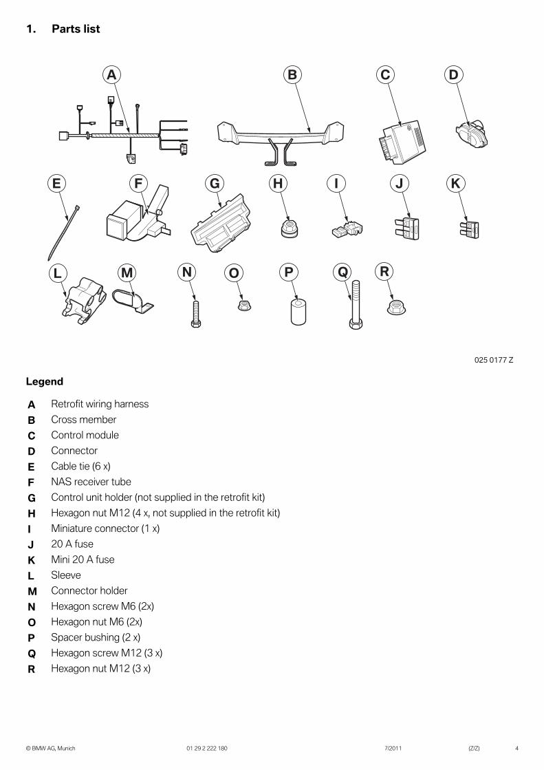
Legend
A Retrofit wiring harness
B Cross member
C Control module
D Connector
E Cable tie (6 x)
F NAS receiver tube
G Control unit holder (not supplied in the retrofit kit)
H Hexagon nut M12 (4 x, not supplied in the retrofit kit)
I Miniature connector (1 x)
J 20 A fuse
K Mini 20 A fuse
L Sleeve
M Connector holder
N Hexagon screw M6 (2x)
O Hexagon nut M6 (2x)
P Spacer bushing (2 x)
Q Hexagon screw M12 (3 x)
R Hexagon nut M12 (3 x)
A
E F KI JG H
B DC
ML N O RQP
025 0177 Z
1. Parts list
7/201101 29 2 222 180© BMW AG, Munich (Z/Z) 4
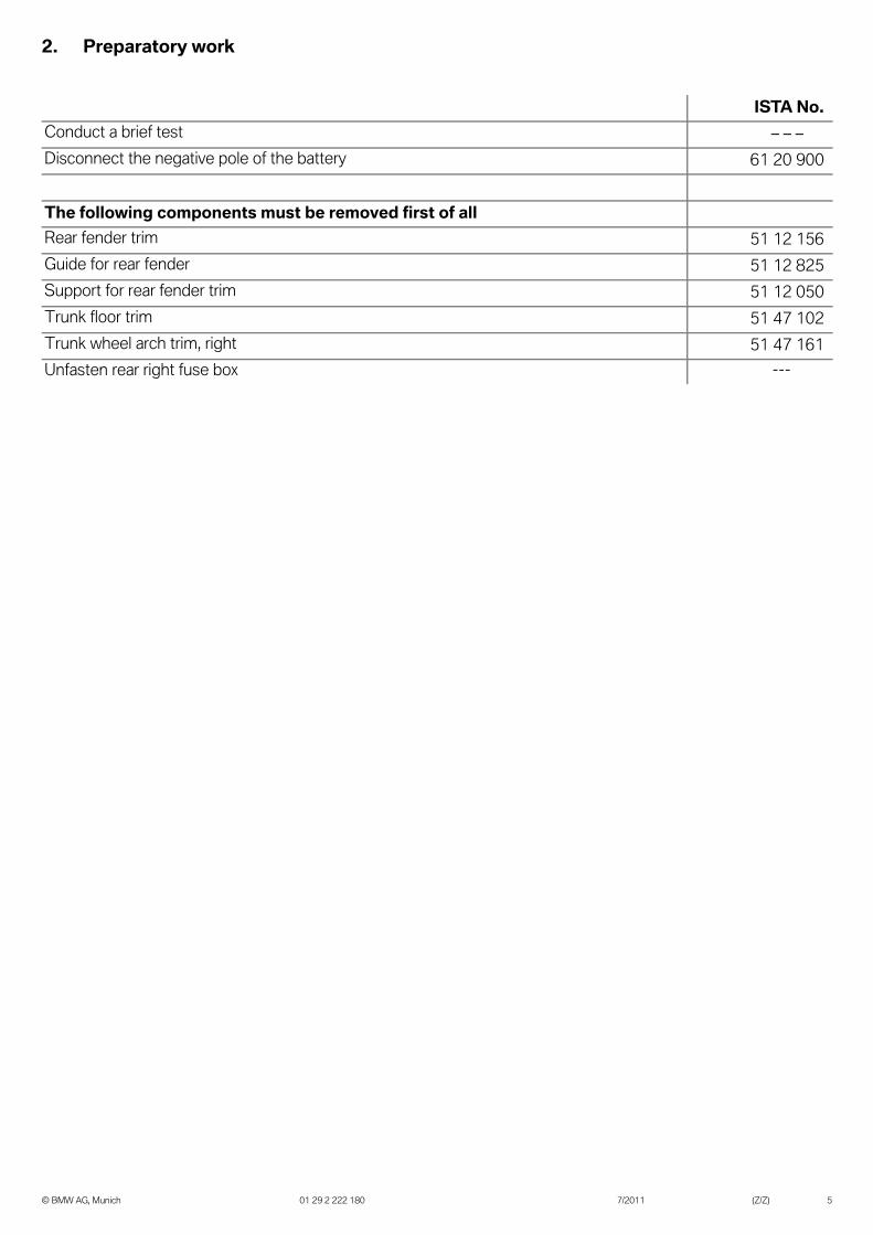
ISTA No.
Conduct a brief test – – –
Disconnect the negative pole of the battery 61 20 900
The following components must be removed first of all
Rear fender trim 51 12 156
Guide for rear fender 51 12 825
Support for rear fender trim 51 12 050
Trunk floor trim 51 47 102
Trunk wheel arch trim, right 51 47 161
Unfasten rear right fuse box ---
2. Preparatory work
7/201101 29 2 222 180© BMW AG, Munich (Z/Z) 5

Item Designation Signal Cable color / Cross-section
Connection location in the car Abbreviation / Slot
A Retrofit wiring harness --- --- --- ---
A1 SW 7-pin socket casing --- --- To socket D ---
A2 SW 6-pin pin housing --- --- To rear fender tail module plug X258*1S
A3 SW 2-pin socket casing --- --- To Comfort Access antenna E27*1B
A4 SW 6-pin socket casing --- --- To tail module plug X258*1B
A5 SW 2-pin pin housing --- --- To plug E27*1B on the car E27*1S
A6 SW 20-pin socket casing --- --- To trailer module C A36*1B
A7 Ring eyelet M6 Terminal 31 BR
2.50 mm2
To earth support point, right-hand rear wheel arch
Z10*14B
A8 Cable open Terminal 49R
BL/BR
0.35 mm2
With miniature connector I to BL/BR cable on right tail light
E57*1BPIN 2
A9 Flat spring contact Terminal 30 RT
2.50 mm2
To rear right fuse box Z2 Z2*1BPIN 1
A10 Flat spring contact Terminal 30 RT/SW
2.50 mm2
To rear right fuse box Z2 Z2*5BPIN 2
A11 SW 4-pin socket casing--- ---
To the plug of the trailer module preparation behind the rear right fuse box
X18*1B
A1
A2
A10
A5A3
A
A4
A11
A9
A8
A7
A6025 0179 Z
3. Connection diagram
7/201101 29 2 222 180© BMW AG, Munich (Z/Z) 6
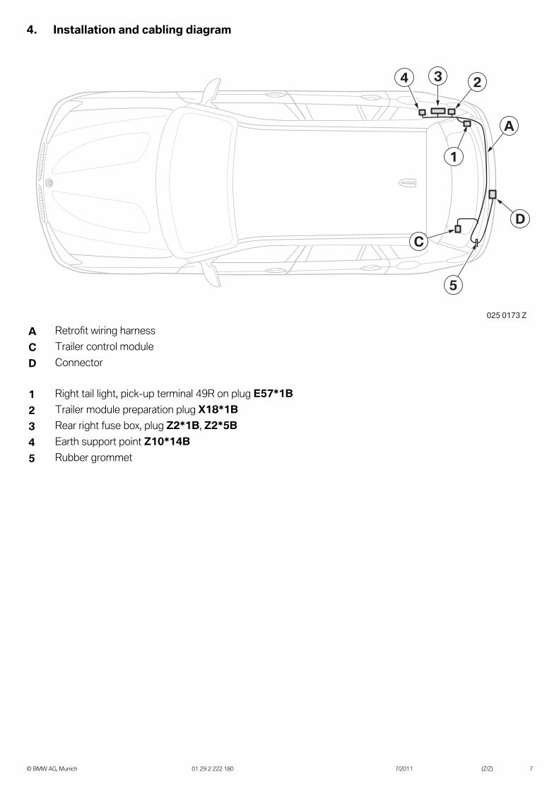
A Retrofit wiring harness
C Trailer control module
D Connector
1 Right tail light, pick-up terminal 49R on plug E57*1B
2 Trailer module preparation plug X18*1B
3 Rear right fuse box, plug Z2*1B, Z2*5B
4 Earth support point Z10*14B
5 Rubber grommet
3
1
5
C
D
24
A
025 0173 Z
4. Installation and cabling diagram
7/201101 29 2 222 180© BMW AG, Munich (Z/Z) 7

Note the tightening torque value: 120 Nm.
Assemble the rear carrier system as follows:
- Screw sleeve L using hexagon screws Q and hexagon nuts R to cross member B
- Screw socket holder M using hexagon screws N, spacer bushes P and hexagon nuts O to transverse pipe B
Remove the rubber grommet (1) and route plug X258*1S, SW 6-pin pin housing, and E27*1B, SW 2-pin socket casing, through the existing hole into the trunk.
Route branches A1-A3 from the interior through the hole and place the rubber grommet (1) in the hole and make it water-tight.
Note the tightening torque value: 108 Nm.
Screw transverse pipe B into position using hexagon nuts H.
Clip socket D onto socket holder M.
L
Q
R
P
O
N
M
B
025 0178 Z
1
X258*1S
E27*1B025 0163 Z
1
A2
A1
A3025 0165 Z
B
HH
D
M
025 0161 Z
5. Installing the trailer hitch system
7/201101 29 2 222 180© BMW AG, Munich (Z/Z) 8

5. Installing the trailer hitch system
Connect branch A1, SW 7-pin socket casing, to socket D.
Secure retrofit wiring harness A using cable tie E to transverse pipe B.
DA1 025 0162 Z
BA
E
025 0166 Z
7/201101 29 2 222 180© BMW AG, Munich (Z/Z) 9

6. Installing and connecting the retrofit wiring harness
Connect car plug X258*1S, SW 6-pin pin housing and plug E27*1B, SW 2-pin socket casing, to branches A4 and A5.
If a new control module holder G is required, the battery needs to be temporary relocated.
Place control module holder G in the rear left trunk.
Place control module C in equipment holder G.
Connect branch A6, SW 20-pin socket casing, to control module C.
Connect branch A8 using miniature connector I, to the BL/BR cable of the same color from plug E57*1B PIN 2 of the right tail light.
Connect branch A11 to the tied-back plug of trailer module preparation X18*1B, SW 4-pin socket casing.
X258*1S
E27*1B
A4
A5
025 0164 Z
C
G A6
025 0172 Z
E57*1B
I
A8
025 0168 Z
X18*1B
A11
025 0167 Z
7/201101 29 2 222 180© BMW AG, Munich (Z/Z) 10

6. Installing and connecting the retrofit wiring harness
Fuses can fall out when plugs are connected to the fuse holder (1). Ensure that all the fuses are replaced
in their correct position.
Route branches A9-A10 to the rear right fuse box and connect as follows:
- Branch A9, RT cable, to PIN 1 of plug Z2*1B, SW 7-pin socket casing
- Branch A10, RT/SW cable, to PIN 2 of plug Z2*5B, NT 10+5-pin socket casing
Connect all plugs to the fuse holder (1).
Place fuse K into slot F145 of the rear right fuse box (1).
Place fuse J into slot F100 of the rear right fuse box (1).
Screw branch A7 to earth support point Z10*14B in the rear right wheel arch.
1
A9-A10Z2*5B
Z2*1B025 0171 Z
F100
F145
1
K
J
025 0091 Z
Z10*14B
A7
025 0170 Z
7/201101 29 2 222 180© BMW AG, Munich (Z/Z) 11
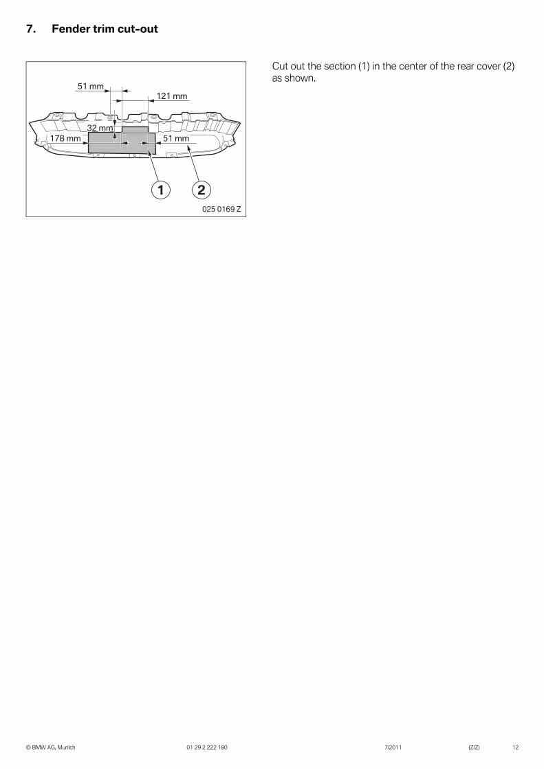
7. Fender trim cut-out
Cut out the section (1) in the center of the rear cover (2) as shown.
51 mm
121 mm
51 mm178 mm
32 mm
1 2
025 0169 Z
7/201101 29 2 222 180© BMW AG, Munich (Z/Z) 12
8. Concluding work and coding
The retrofit system requires programming / coding.
- Connect the battery
- Carry out a vehicle test using the ISTA system and note or work through any entered error memory.
- Change in the ISTA/P car programming
- Select the "Removable trailer tow hitch" retrofit via the – Conversion – path and work through the created action plan
- If using ISTA/P, please note the instructions in the ISTA/P application documentation
7/201101 29 2 222 180© BMW AG, Munich (Z/Z) 13

9. Wiring diagram
Legend
Cable colors
A1* SW 7-pin socket casing, to socket D
A2* SW 6-pin pin housing, to plug X258*1B
A3* SW 2-pin socket casing, to plug E27*1S of the Comfort Access antenna
A4* SW 6-pin socket casing, to plug X258*1S
A5* SW 2-pin pin housing, to plug E27*1B of the Comfort Access antenna
A6 SW 20-pin socket casing, to trailer module C*
A7 Ring eyelet M6, to earth support point, rear right wheel arch Z10*14B
A8* Cable open, with miniature connector I* to the same-color cable on right tail light, plug E57*1B
A9* Connect socket contact to plug Z2*1B of rear right fuse box Z2
A10* Connect socket contact to plug Z2*5B of rear right fuse box Z2
A11* SW 4-pin socket casing to plug X18*1B
C* Trailer module
D* Socket
BL Blue GR Gray RT RedBO Bordeaux L-GN Light green SW BlackBR Brown NT Natural TR TransparentGE Yellow OR Orange VI VioletGN Green RO Pink WS White
C*
Z2Z2
D*
A1*
A6*
A8*
A9*A10*
A7*Z10*14B
Z2*5B Z2*1B
A36*1B
A11*A57*1BX18*1B
A3*E27*1B
A5*E27*1S
A2*X258*1S
A4*
X258*1S E27*1B
X258*1B E27*1S
X258*1B
A6*A36*1B
025 0160 Z
7/201101 29 2 222 180© BMW AG, Munich (Z/Z) 14
10. Information for the customer
BMW X3 Trailer Hitch Guidelines and Cautions
These Guideline Sheets should be left in the vehicle (for customer reference) after installation of the Trailer Hitch
----------------------------------------------------------------------------------------------------------------------------------------
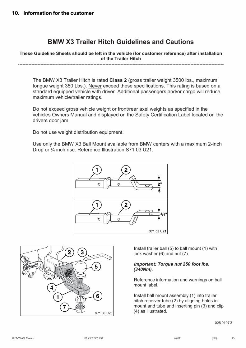
The BMW X3 Trailer Hitch is rated Class 2 (gross trailer weight 3500 lbs., maximum tongue weight 350 Lbs.). Never exceed these specifications. This rating is based on a standard equipped vehicle with driver. Additional passengers and/or cargo will reduce maximum vehicle/trailer ratings.
Do not exceed gross vehicle weight or front/rear axel weights as specified in the
vehicles Owners Manual and displayed on the Safety Certification Label located on the drivers door jam.
Do not use weight distribution equipment.
Use only the BMW X3 Ball Mount available from BMW centers with a maximum 2-inch
Drop or ¾ inch rise. Reference Illustration S71 03 U21.
Install trailer ball (5) to ball mount (1) with lock washer (6) and nut (7).
Important: Torque nut 250 foot lbs. (340Nm).
Reference information and warnings on ball
mount label. Install ball mount assembly (1) into trailer
hitch receiver tube (2) by aligning holes in mount and tube and inserting pin (3) and clip (4) as illustrated.
025 0197 Z
7/201101 29 2 222 180© BMW AG, Munich (Z/Z) 15

10. Information for the customer
BMW X3 Trailer Hitch Guidelines and Cautions
These Guideline Sheets should be left in the vehicle (for customer reference) after installation of the Trailer Hitch
----------------------------------------------------------------------------------------------------------------------------- -----------
Before attaching, loading, or towing a trailer please read the brochure available on line at the NHTSA Web Site www.nhtsa.gov or available by calling the DOT Auto Safety Hotline at 888-327-4236): TOWING A TRAILER – Being Equipped for Safety, NHTSA Publication DOT HS 809 433, April 2002.
Check all connections (mechanical and electrical) before and during the towing of a
trailer.
Check the function of all vehicle lights and the lights on the trailer before and during the towing of a trailer.
Do not cut, weld, drill or modify the trailer hitch.
Do not modify any wiring or electrical components.
BMW NA does not supply or have an approved electrical brake controller for your
Trailer Hitch.
For trailers with LED lighting, in order to prevent the battery from draining over a long period of time, you should disconnect the wire harness that connects the trailer to the vehicle when the vehicle is not in use.
025 0198 Z
7/201101 29 2 222 180© BMW AG, Munich (Z/Z) 16