Easy to earn money-PTC€¦ · Easy to earn money-PTC । । । । PTC (paid to click)। । । । । । PTC
PTC_CE_BSD_7.2_us_mp.mcdx
Mathcad ® Enabled Content Copyright © 2011 Knovel Corp.
Building Structural Design Thomas P. Magner, P.E. © 2011 Parametric Technology Corp.Chapter 7: Reinforced Concrete Column and Wall Footings
7.2 Pile Footings
DisclaimerWhile Knovel and PTC have made every effort to ensure that the calculations, engineering solutions, diagrams and other information (collectively “Solution”) presented in this Mathcad worksheet are sound from the engineering standpoint and accurately represent the content of the book on which the Solution is based, Knovel and PTC do not give any warranties or representations, express or implied,including with respect to fitness, intended purpose, use or merchantability and/or correctness or accuracy of this Solution.
Array origin:
≔ORIGIN 0
Description
Pile supported footings or pile caps are used under columns and walls to distribute the load to thepiles. The plan dimensions of a pile footing are determined by the number and the arrangement of thepiles and the required minimum spacing between the piles.
This application determines minimum required pile cap thickness and the maximum size and minimum number of reinforcing bars for pile caps with from 2 to 20 piles in a group. Pile diameter and spacing, and the size of the supported rectangular pier or wall may be specified by the user. The applicationuses the Strength Design Method of ACI 318-89.
The required input includes the pile capacity at service load (unfactored loads) and the plan dimensions of the column or wall. The user may also enter material properties and variables designated as "project constants" in this application.
The material properties include strength of the concrete and the reinforcement, unit weight of concrete, unit weight of reinforced concrete, and the preferred reinforcement ratio.
The project constants include pile diameter, minimum pile spacing, edge distance, and multiples used for rounding the pile coordinates, the pile cap depth and the plan dimensions of the pile caps.
Mathcad ® Enabled ContentCopyright © 2011 Knovel Corp.All rights reserved.
Page 1 of 41
PTC_CE_BSD_7.2_us_mp.mcdx
Reference: ACI 318-89 "Building Code Requirements for Reinforced Concrete." (Revised 1992)
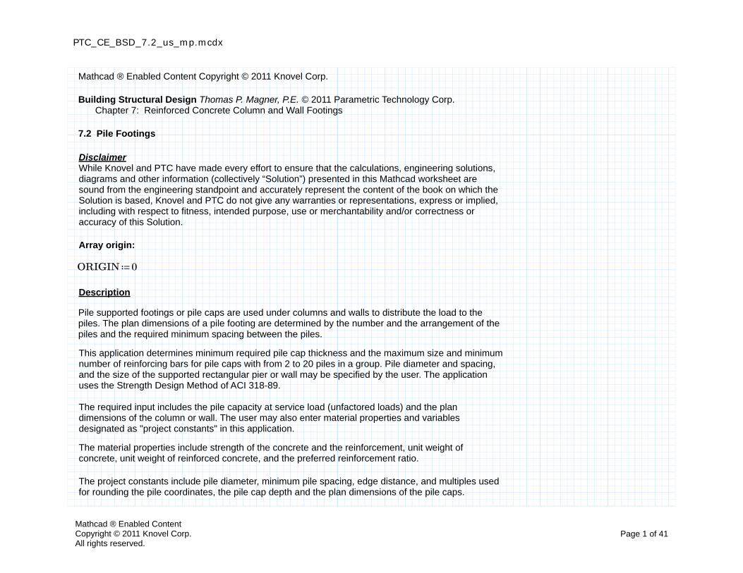
Input
Input Variables
Enter service load pile capacity, number of piles in group, and pier or wall dimensions.
Pile capacity at service loads: ≔Pcap 80 kip
Number of piles in group: ≔N 8
Column width: ≔Cx 24 in
Column depth: ≔Cy 24 in
If the footing supports a wall, enter any wall length greater than or equal to the dimension of thefooting parallel to the wall.
Mathcad ® Enabled ContentCopyright © 2011 Knovel Corp.All rights reserved.
Page 2 of 41
PTC_CE_BSD_7.2_us_mp.mcdx
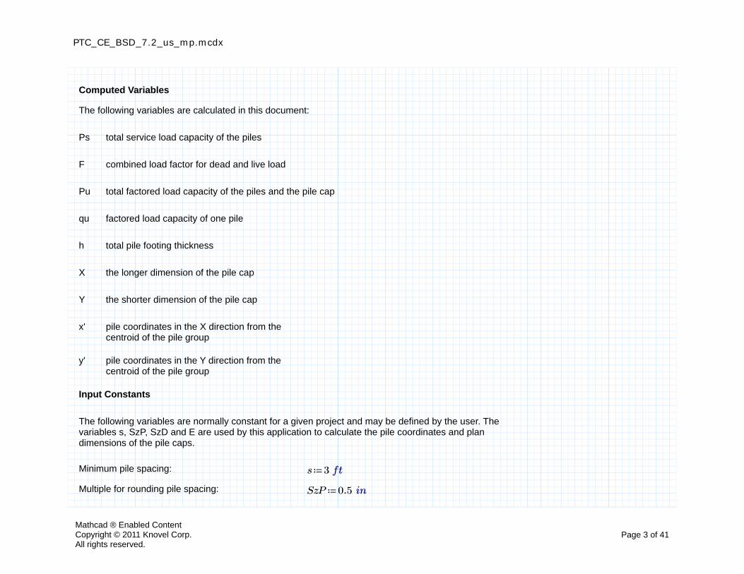
Computed Variables
The following variables are calculated in this document:
Ps total service load capacity of the piles
F combined load factor for dead and live load
Pu total factored load capacity of the piles and the pile cap
qu factored load capacity of one pile
h total pile footing thickness
X the longer dimension of the pile cap
Y the shorter dimension of the pile cap
x' pile coordinates in the X direction from the centroid of the pile group
y' pile coordinates in the Y direction from the centroid of the pile group
Input Constants
The following variables are normally constant for a given project and may be defined by the user. The variables s, SzP, SzD and E are used by this application to calculate the pile coordinates and plan dimensions of the pile caps.
Minimum pile spacing: ≔s 3 ft
Multiple for rounding pile spacing: ≔SzP 0.5 in
Mathcad ® Enabled ContentCopyright © 2011 Knovel Corp.All rights reserved.
Page 3 of 41
PTC_CE_BSD_7.2_us_mp.mcdx
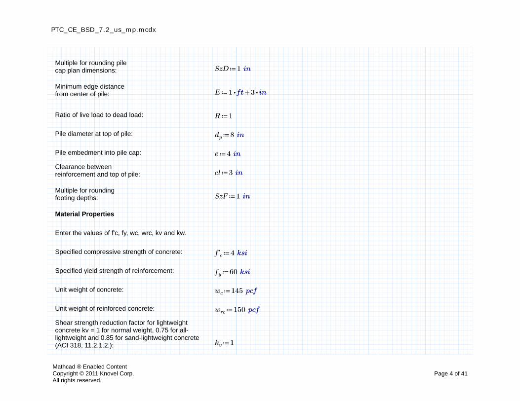
Multiple for rounding pile cap plan dimensions: ≔SzD 1 in
Minimum edge distance from center of pile: ≔E +⋅1 ft ⋅3 in
Ratio of live load to dead load: ≔R 1
Pile diameter at top of pile: ≔dp 8 in
Pile embedment into pile cap: ≔e 4 in
Clearance between reinforcement and top of pile: ≔cl 3 in
Multiple for rounding footing depths: ≔SzF 1 in
Material Properties
Enter the values of f'c, fy, wc, wrc, kv and kw.
Specified compressive strength of concrete: ≔f'c 4 ksi
Specified yield strength of reinforcement: ≔fy 60 ksi
Unit weight of concrete: ≔wc 145 pcf
Unit weight of reinforced concrete: ≔wrc 150 pcf
Shear strength reduction factor for lightweightconcrete kv = 1 for normal weight, 0.75 for all-lightweight and 0.85 for sand-lightweight concrete(ACI 318, 11.2.1.2.): ≔kv 1
Mathcad ® Enabled ContentCopyright © 2011 Knovel Corp.All rights reserved.
Page 4 of 41
PTC_CE_BSD_7.2_us_mp.mcdx
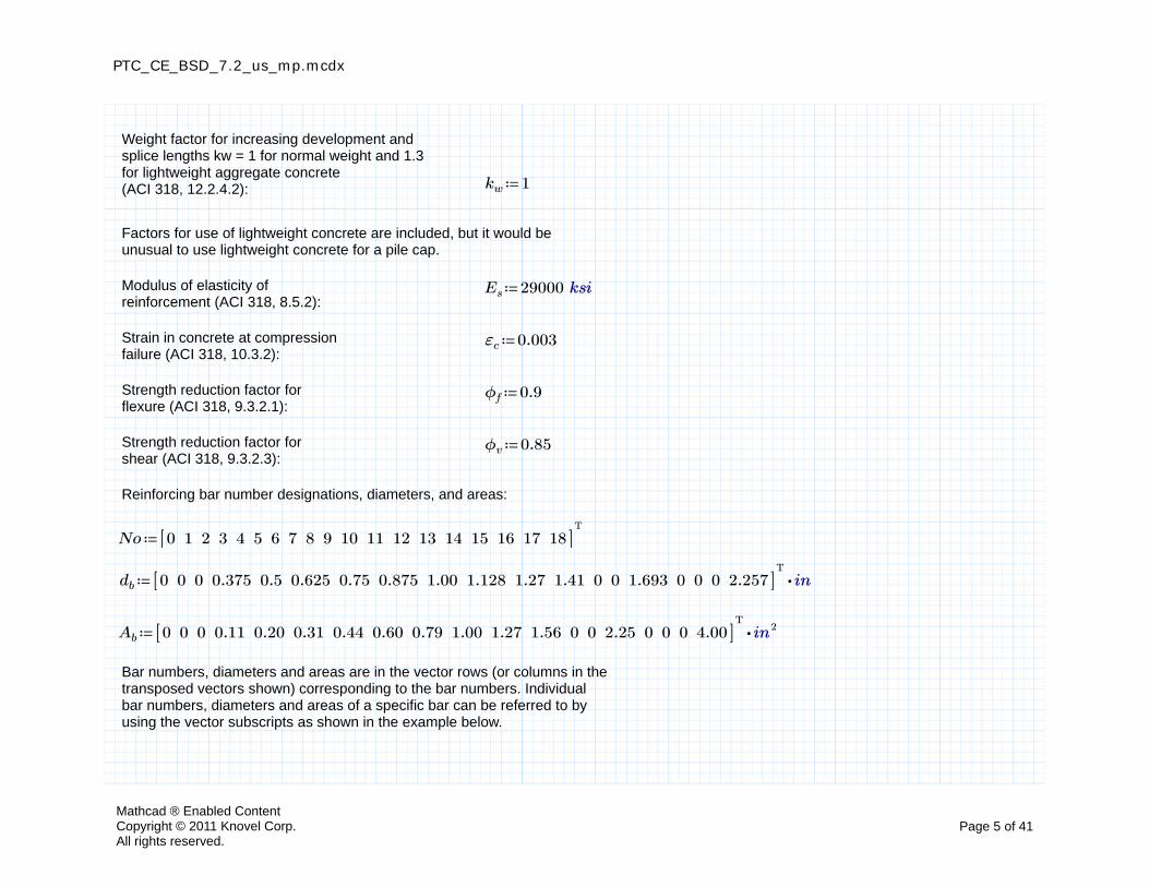
Weight factor for increasing development and splice lengths kw = 1 for normal weight and 1.3 for lightweight aggregate concrete(ACI 318, 12.2.4.2): ≔kw 1
Factors for use of lightweight concrete are included, but it would be unusual to use lightweight concrete for a pile cap.
Modulus of elasticity of reinforcement (ACI 318, 8.5.2):
≔Es 29000 ksi
Strain in concrete at compression failure (ACI 318, 10.3.2):
≔εc 0.003
Strength reduction factor for flexure (ACI 318, 9.3.2.1):
≔ϕf 0.9
Strength reduction factor for shear (ACI 318, 9.3.2.3):
≔ϕv 0.85
Reinforcing bar number designations, diameters, and areas:
≔NoT
0 1 2 3 4 5 6 7 8 9 10 11 12 13 14 15 16 17 18[[ ]]
≔db ⋅T
0 0 0 0.375 0.5 0.625 0.75 0.875 1.00 1.128 1.27 1.41 0 0 1.693 0 0 0 2.257[[ ]] in
≔Ab ⋅T
0 0 0 0.11 0.20 0.31 0.44 0.60 0.79 1.00 1.27 1.56 0 0 2.25 0 0 0 4.00[[ ]] in2
Bar numbers, diameters and areas are in the vector rows (or columns in the transposed vectors shown) corresponding to the bar numbers. Individual bar numbers, diameters and areas of a specific bar can be referred to by using the vector subscripts as shown in the example below.
Mathcad ® Enabled ContentCopyright © 2011 Knovel Corp.All rights reserved.
Page 5 of 41
PTC_CE_BSD_7.2_us_mp.mcdx
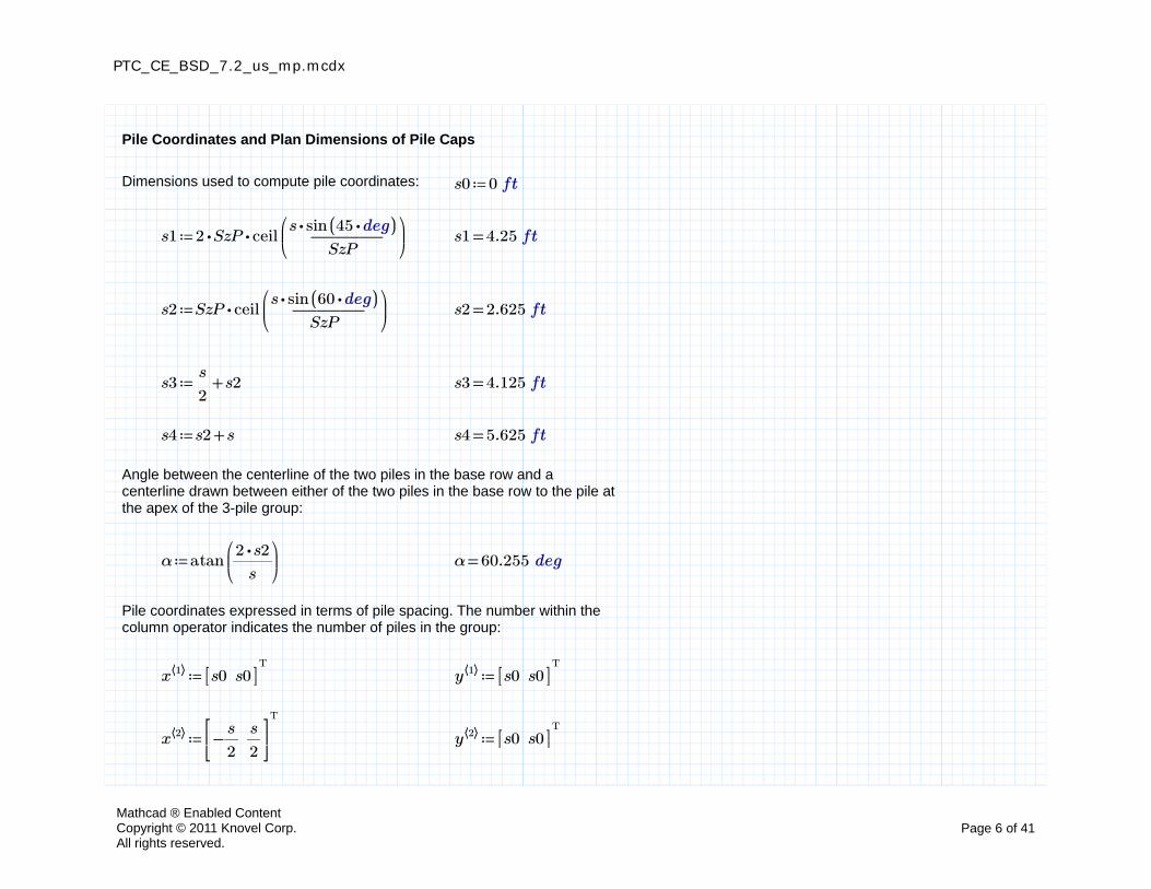
Pile Coordinates and Plan Dimensions of Pile Caps
Dimensions used to compute pile coordinates: ≔s0 0 ft
≔s1 ⋅⋅2 SzP ceil⎛⎜⎝―――――
⋅s sin (( ⋅45 deg))SzP
⎞⎟⎠
=s1 4.25 ft
≔s2 ⋅SzP ceil⎛⎜⎝―――――
⋅s sin (( ⋅60 deg))SzP
⎞⎟⎠
=s2 2.625 ft
≔s3 +―s
2s2 =s3 4.125 ft
≔s4 +s2 s =s4 5.625 ft
Angle between the centerline of the two piles in the base row and a centerline drawn between either of the two piles in the base row to the pile at the apex of the 3-pile group:
≔α atan⎛⎜⎝――
⋅2 s2
s
⎞⎟⎠
=α 60.255 deg
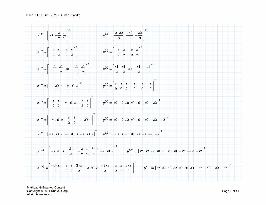
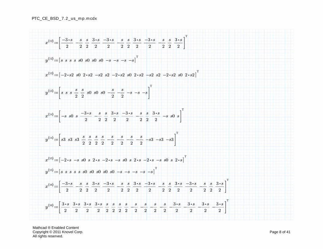
Pile coordinates expressed in terms of pile spacing. The number within the column operator indicates the number of piles in the group:
≔x⟨⟨1⟩⟩T
s0 s0[[ ]] ≔y⟨⟨1⟩⟩T
s0 s0[[ ]]
≔x⟨⟨2⟩⟩T
−―s
2―s
2
⎡⎢⎣
⎤⎥⎦
≔y⟨⟨2⟩⟩T
s0 s0[[ ]]
Mathcad ® Enabled ContentCopyright © 2011 Knovel Corp.All rights reserved.
Page 6 of 41
PTC_CE_BSD_7.2_us_mp.mcdx
≔x⟨⟨3⟩⟩T
s0 −―s
2―s
2
⎡⎢⎣
⎤⎥⎦
≔y⟨⟨3⟩⟩T
――⋅2 s2
3−―
s2
3−―
s2
3
⎡⎢⎣
⎤⎥⎦
≔x⟨⟨4⟩⟩T
−―s
2―s
2−―
s
2―s
2
⎡⎢⎣
⎤⎥⎦
≔y⟨⟨4⟩⟩T
−―s
2―s
2−―
s
2―s
2
⎡⎢⎣
⎤⎥⎦
≔x⟨⟨5⟩⟩T
−―s1
2―s1
2s0 −―
s1
2―s1
2
⎡⎢⎣
⎤⎥⎦
≔y⟨⟨5⟩⟩T
―s1
2―s1
2s0 −―
s1
2−―
s1
2
⎡⎢⎣
⎤⎥⎦
≔x⟨⟨6⟩⟩T
−s s0 s −s s0 s[[ ]] ≔y⟨⟨6⟩⟩T
―s
2―s
2―s
2−―
s
2−―
s
2−―
s
2
⎡⎢⎣
⎤⎥⎦
≔x⟨⟨7⟩⟩T
−―s
2―s
2−s s0 s −―
s
2―s
2
⎡⎢⎣
⎤⎥⎦
≔y⟨⟨7⟩⟩T
s2 s2 s0 s0 s0 −s2 −s2[[ ]]
≔x⟨⟨8⟩⟩T
−s s0 s −―s
2―s
2−s s0 s
⎡⎢⎣
⎤⎥⎦
≔y⟨⟨8⟩⟩T
s2 s2 s2 s0 s0 −s2 −s2 −s2[[ ]]
≔x⟨⟨9⟩⟩T
−s s0 s −s s0 s −s s0 s[[ ]] ≔y⟨⟨9⟩⟩T
s s s s0 s0 s0 −s −s −s[[ ]]
≔x⟨⟨10⟩⟩T
−s s0 s ――⋅−3 s
2−―
s
2―s
2――
⋅3 s
2−s s0 s
⎡⎢⎣
⎤⎥⎦
≔y⟨⟨10⟩⟩T
s2 s2 s2 s0 s0 s0 s0 −s2 −s2 −s2[[ ]]
≔x⟨⟨11⟩⟩T
――⋅−3 s
2−―
s
2―s
2――
⋅3 s
2−s s0 s ――
⋅−3 s
2−―
s
2―s
2――
⋅3 s
2
⎡⎢⎣
⎤⎥⎦
≔y⟨⟨11⟩⟩T
s2 s2 s2 s2 s0 s0 s0 −s2 −s2 −s2 −s2[[ ]]
Mathcad ® Enabled ContentCopyright © 2011 Knovel Corp.All rights reserved.
Page 7 of 41
PTC_CE_BSD_7.2_us_mp.mcdx
≔x⟨⟨12⟩⟩T
――⋅−3 s
2−―
s
2―s
2――
⋅3 s
2――
⋅−3 s
2−―
s
2―s
2――
⋅3 s
2――
⋅−3 s
2−―
s
2―s
2――
⋅3 s
2
⎡⎢⎣
⎤⎥⎦
≔y⟨⟨12⟩⟩T
s s s s s0 s0 s0 s0 −s −s −s −s[[ ]]
≔x⟨⟨13⟩⟩T
⋅−2 s2 s0 ⋅2 s2 −s2 s2 ⋅−2 s2 s0 ⋅2 s2 −s2 s2 ⋅−2 s2 s0 ⋅2 s2[[ ]]
≔y⟨⟨13⟩⟩T
s s s ―s
2―s
2s0 s0 s0 −―
s
2−―
s
2−s −s −s
⎡⎢⎣
⎤⎥⎦
≔x⟨⟨14⟩⟩T
−s s0 s ――⋅−3 s
2−―
s
2―s
2――
⋅3 s
2――
⋅−3 s
2−―
s
2―s
2――
⋅3 s
2−s s0 s
⎡⎢⎣
⎤⎥⎦
≔y⟨⟨14⟩⟩T
s3 s3 s3 ―s
2―s
2―s
2―s
2−―
s
2−―
s
2−―
s
2−―
s
2−s3 −s3 −s3
⎡⎢⎣
⎤⎥⎦
≔x⟨⟨15⟩⟩T
⋅−2 s −s s0 s ⋅2 s ⋅−2 s −s s0 s ⋅2 s ⋅−2 s −s s0 s ⋅2 s[[ ]]
≔y⟨⟨15⟩⟩T
s s s s s s0 s0 s0 s0 s0 −s −s −s −s −s[[ ]]
≔x⟨⟨16⟩⟩T
――⋅−3 s
2−―
s
2―s
2――
⋅3 s
2――
⋅−3 s
2−―
s
2―s
2――
⋅3 s
2――
⋅−3 s
2−―
s
2―s
2――
⋅3 s
2――
⋅−3 s
2−―
s
2―s
2――
⋅3 s
2
⎡⎢⎣
⎤⎥⎦
≔y⟨⟨16⟩⟩T
――⋅3 s
2――
⋅3 s
2――
⋅3 s
2――
⋅3 s
2―s
2―s
2―s
2―s
2−―
s
2−―
s
2−―
s
2−―
s
2−――
⋅3 s
2−――
⋅3 s
2−――
⋅3 s
2−――
⋅3 s
2
⎡⎢⎣
⎤⎥⎦
Mathcad ® Enabled ContentCopyright © 2011 Knovel Corp.All rights reserved.
Page 8 of 41
PTC_CE_BSD_7.2_us_mp.mcdx
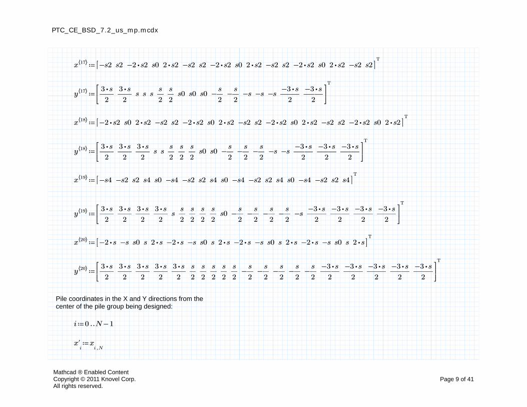
≔x⟨⟨17⟩⟩T
−s2 s2 ⋅−2 s2 s0 ⋅2 s2 −s2 s2 ⋅−2 s2 s0 ⋅2 s2 −s2 s2 ⋅−2 s2 s0 ⋅2 s2 −s2 s2[[ ]]
≔y⟨⟨17⟩⟩T
――⋅3 s
2――
⋅3 s
2s s s ―
s
2―s
2s0 s0 s0 −―
s
2−―
s
2−s −s −s ――
⋅−3 s
2――
⋅−3 s
2
⎡⎢⎣
⎤⎥⎦
≔x⟨⟨18⟩⟩T
⋅−2 s2 s0 ⋅2 s2 −s2 s2 ⋅−2 s2 s0 ⋅2 s2 −s2 s2 ⋅−2 s2 s0 ⋅2 s2 −s2 s2 ⋅−2 s2 s0 ⋅2 s2[[ ]]
≔y⟨⟨18⟩⟩T
――⋅3 s
2――
⋅3 s
2――
⋅3 s
2s s ―
s
2―s
2―s
2s0 s0 −―
s
2−―
s
2−―
s
2−s −s ――
⋅−3 s
2――
⋅−3 s
2――
⋅−3 s
2
⎡⎢⎣
⎤⎥⎦
≔x⟨⟨19⟩⟩T
−s4 −s2 s2 s4 s0 −s4 −s2 s2 s4 s0 −s4 −s2 s2 s4 s0 −s4 −s2 s2 s4[[ ]]
≔y⟨⟨19⟩⟩T
――⋅3 s
2――
⋅3 s
2――
⋅3 s
2――
⋅3 s
2s ―
s
2―s
2―s
2―s
2s0 −―
s
2−―
s
2−―
s
2−―
s
2−s ――
⋅−3 s
2――
⋅−3 s
2――
⋅−3 s
2――
⋅−3 s
2
⎡⎢⎣
⎤⎥⎦
≔x⟨⟨20⟩⟩T
⋅−2 s −s s0 s ⋅2 s ⋅−2 s −s s0 s ⋅2 s ⋅−2 s −s s0 s ⋅2 s ⋅−2 s −s s0 s ⋅2 s[[ ]]
≔y⟨⟨20⟩⟩T
――⋅3 s
2――
⋅3 s
2――
⋅3 s
2――
⋅3 s
2――
⋅3 s
2―s
2―s
2―s
2―s
2―s
2−―
s
2−―
s
2−―
s
2−―
s
2−―
s
2――
⋅−3 s
2――
⋅−3 s
2――
⋅−3 s
2――
⋅−3 s
2――
⋅−3 s
2
⎡⎢⎣
⎤⎥⎦
Pile coordinates in the X and Y directions from the center of the pile group being designed:
≔i ‥0 −N 1
≔x'i
x,i N
Mathcad ® Enabled ContentCopyright © 2011 Knovel Corp.All rights reserved.
Page 9 of 41
PTC_CE_BSD_7.2_us_mp.mcdx
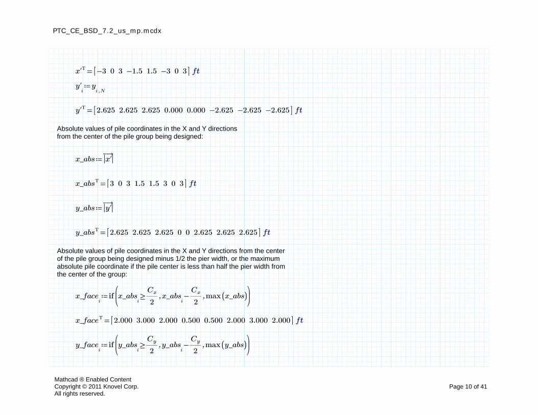
=Tx' −3 0 3 −1.5 1.5 −3 0 3[[ ]] ft
≔y'i
y,i N
=Ty' 2.625 2.625 2.625 0.000 0.000 −2.625 −2.625 −2.625[[ ]] ft
Absolute values of pile coordinates in the X and Y directions from the center of the pile group being designed:
≔x_abs→―
||x'||
=Tx_abs 3 0 3 1.5 1.5 3 0 3[[ ]] ft
≔y_abs→―
||y'||
=Ty_abs 2.625 2.625 2.625 0 0 2.625 2.625 2.625[[ ]] ft
Absolute values of pile coordinates in the X and Y directions from the center of the pile group being designed minus 1/2 the pier width, or the maximum absolute pile coordinate if the pile center is less than half the pier width from the center of the group:
≔x_facei
if⎛⎜⎝
,,≥x_absi
――Cx
2−x_abs
i――Cx
2max ((x_abs))
⎞⎟⎠
=Tx_face 2.000 3.000 2.000 0.500 0.500 2.000 3.000 2.000[[ ]] ft
≔y_facei
if⎛⎜⎝
,,≥y_absi
―Cy
2−y_abs
i―Cy
2max ((y_abs))
⎞⎟⎠
Mathcad ® Enabled ContentCopyright © 2011 Knovel Corp.All rights reserved.
Page 10 of 41
PTC_CE_BSD_7.2_us_mp.mcdx
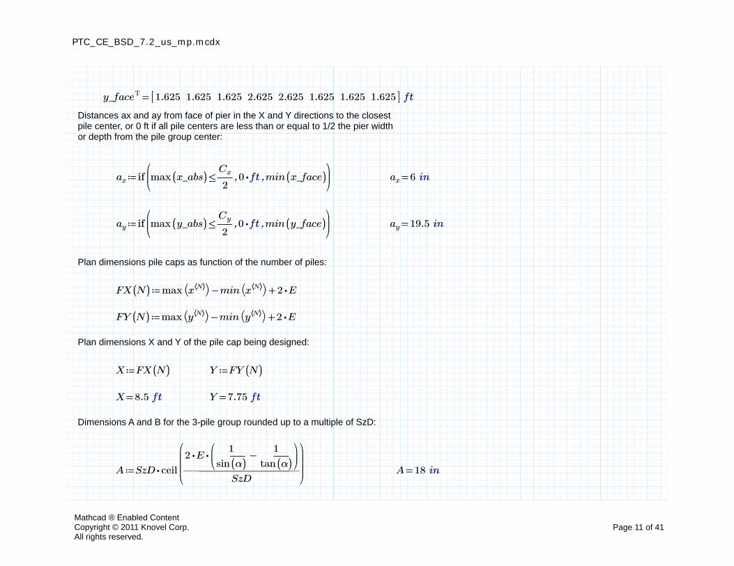
=Ty_face 1.625 1.625 1.625 2.625 2.625 1.625 1.625 1.625[[ ]] ft
Distances ax and ay from face of pier in the X and Y directions to the closest pile center, or 0 ft if all pile centers are less than or equal to 1/2 the pier width or depth from the pile group center:
≔ax if⎛⎜⎝
,,≤max ((x_abs)) ――Cx
2⋅0 ft min ((x_face))
⎞⎟⎠
=ax 6 in
≔ay if⎛⎜⎝
,,≤max ((y_abs)) ―Cy
2⋅0 ft min ((y_face))
⎞⎟⎠
=ay 19.5 in
Plan dimensions pile caps as function of the number of piles:
≔FX ((N)) +−max ⎛⎝x⟨⟨N⟩⟩⎞⎠ min ⎛⎝x⟨⟨N⟩⟩⎞⎠ ⋅2 E
≔FY ((N)) +−max ⎛⎝y⟨⟨N⟩⟩⎞⎠ min ⎛⎝y⟨⟨N⟩⟩⎞⎠ ⋅2 E
Plan dimensions X and Y of the pile cap being designed:
≔X FX ((N)) ≔Y FY ((N))
=X 8.5 ft =Y 7.75 ft
Dimensions A and B for the 3-pile group rounded up to a multiple of SzD:
≔A ⋅SzD ceil
⎛⎜⎜⎜⎝――――――――
⋅⋅2 E⎛⎜⎝
−―――1
sin ((α))―――
1
tan ((α))
⎞⎟⎠
SzD
⎞⎟⎟⎟⎠
=A 18 in
Mathcad ® Enabled ContentCopyright © 2011 Knovel Corp.All rights reserved.
Page 11 of 41
PTC_CE_BSD_7.2_us_mp.mcdx
≔B ⋅SzD ceil
⎛⎜⎜⎜⎝―――――――――
⋅E⎛⎜⎝
+1 ⋅tan ((α))⎛⎜⎝
−―――1
sin ((α))1
⎞⎟⎠
⎞⎟⎠
SzD
⎞⎟⎟⎟⎠
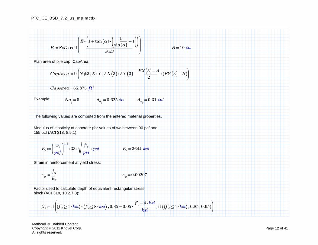
=B 19 in
Plan area of pile cap, CapArea:
≔CapArea if⎛⎜⎝
,,≠N 3 ⋅X Y −⋅FX ((3)) FY ((3)) ⋅――――−FX ((3)) A
2(( −FY ((3)) B))
⎞⎟⎠
=CapArea 65.875 ft2
Example: =No5
5 =db50.625 in =Ab5
0.31 in2
The following values are computed from the entered material properties.
Modulus of elasticity of concrete (for values of wc between 90 pcf and 155 pcf (ACI 318, 8.5.1):
≔Ec ⋅⋅⋅⎛⎜⎝――wc
pcf
⎞⎟⎠
1.5
33‾‾‾‾――f'c
psipsi =Ec 3644 ksi
Strain in reinforcement at yield stress:
≔εy ―fy
Es
=εy 0.00207
Factor used to calculate depth of equivalent rectangular stress block (ACI 318, 10.2.7.3):
≔β1 if⎛⎜⎝
,,⋅⎛⎝ ≥f'c ⋅4 ksi⎞⎠ ⎛⎝ ≤f'c ⋅8 ksi⎞⎠ −0.85 ⋅0.05 ――――−f'c ⋅4 ksi
ksiif ⎛⎝ ,,⎛⎝ ≤f'c ⋅4 ksi⎞⎠ 0.85 0.65⎞⎠
⎞⎟⎠
Mathcad ® Enabled ContentCopyright © 2011 Knovel Corp.All rights reserved.
Page 12 of 41
PTC_CE_BSD_7.2_us_mp.mcdx
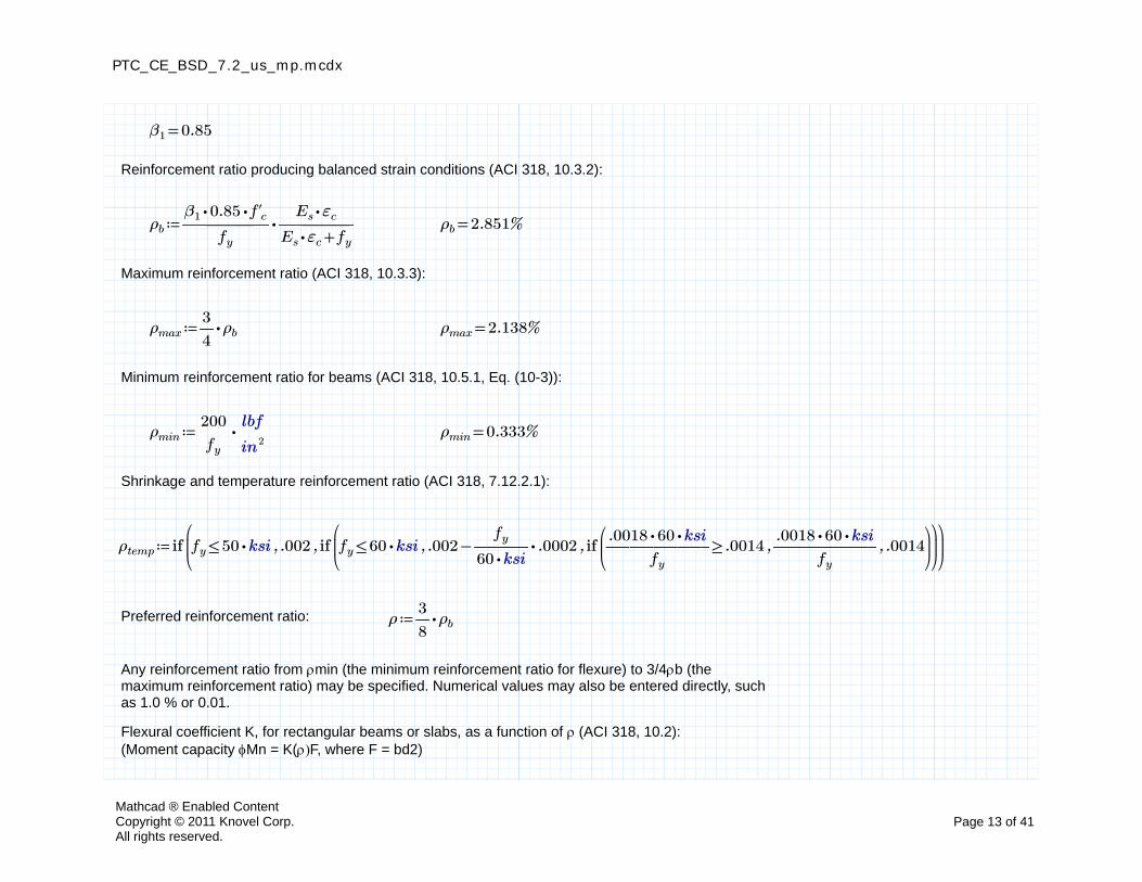
=β1 0.85
Reinforcement ratio producing balanced strain conditions (ACI 318, 10.3.2):
≔ρb ⋅――――⋅⋅β1 0.85 f'c
fy
――――⋅Es εc
+⋅Es εc fy
=ρb %2.851
Maximum reinforcement ratio (ACI 318, 10.3.3):
≔ρmax ⋅―3
4ρb =ρmax %2.138
Minimum reinforcement ratio for beams (ACI 318, 10.5.1, Eq. (10-3)):
≔ρmin ⋅――200
fy
――lbf
in2=ρmin %0.333
Shrinkage and temperature reinforcement ratio (ACI 318, 7.12.2.1):
≔ρtemp if⎛⎜⎝
,,≤fy ⋅50 ksi .002 if⎛⎜⎝
,,≤fy ⋅60 ksi −.002 ⋅―――fy
⋅60 ksi.0002 if
⎛⎜⎝
,,≥―――――⋅⋅.0018 60 ksi
fy
.0014 ―――――⋅⋅.0018 60 ksi
fy
.0014⎞⎟⎠
⎞⎟⎠
⎞⎟⎠
Preferred reinforcement ratio: ≔ρ ⋅―3
8ρb
Any reinforcement ratio from min (the minimum reinforcement ratio for flexure) to 3/4b (the maximum reinforcement ratio) may be specified. Numerical values may also be entered directly, such as 1.0 % or 0.01.
Flexural coefficient K, for rectangular beams or slabs, as a function of (ACI 318, 10.2):(Moment capacity Mn = K(F, where F = bd2)
Mathcad ® Enabled ContentCopyright © 2011 Knovel Corp.All rights reserved.
Page 13 of 41
PTC_CE_BSD_7.2_us_mp.mcdx
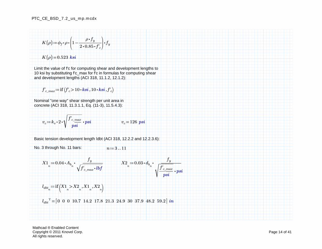
≔K ((ρ)) ⋅⋅⋅ϕf ρ⎛⎜⎝
−1 ――――⋅ρ fy
⋅⋅2 0.85 f'c
⎞⎟⎠
fy
=K ((ρ)) 0.523 ksi
Limit the value of f'c for computing shear and development lengths to 10 ksi by substituting f'c_max for f'c in formulas for computing shear and development lengths (ACI 318, 11.1.2, 12.1.2):
≔f'c_max if ⎛⎝ ,,>f'c ⋅10 ksi ⋅10 ksi f'c⎞⎠
Nominal "one way" shear strength per unit area in concrete (ACI 318, 11.3.1.1, Eq. (11-3), 11.5.4.3):
≔vc ⋅⋅⋅kv 2‾‾‾‾‾‾―――f'c_max
psipsi =vc 126 psi
Basic tension development length ldbt (ACI 318, 12.2.2 and 12.2.3.6):
No. 3 through No. 11 bars: ≔n ‥3 11
≔X1n
⋅⋅0.04 Abn―――――
fy
‾‾‾‾‾‾‾‾‾⋅f'c_max lbf≔X2
n⋅⋅0.03 dbn
―――――fy
⋅‾‾‾‾‾‾―――f'c_max
psipsi
≔ldbtnif ⎛
⎝,,>X1
nX2
nX1
nX2
n⎞⎠
=Tldbt 0 0 0 10.7 14.2 17.8 21.3 24.9 30 37.9 48.2 59.2[[ ]] in
Mathcad ® Enabled ContentCopyright © 2011 Knovel Corp.All rights reserved.
Page 14 of 41
PTC_CE_BSD_7.2_us_mp.mcdx
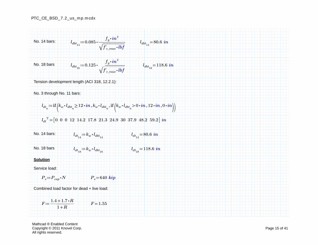
No. 14 bars: ≔ldbt14⋅0.085 ―――――
⋅fy in2
‾‾‾‾‾‾‾‾‾⋅f'c_max lbf=ldbt14
80.6 in
No. 18 bars ≔ldbt18⋅0.125 ―――――
⋅fy in2
‾‾‾‾‾‾‾‾‾⋅f'c_max lbf=ldbt18
118.6 in
Tension development length (ACI 318, 12.2.1):
No. 3 through No. 11 bars:
≔ldtnif ⎛
⎜⎝,,≥⋅kw ldbtn
⋅12 in ⋅kw ldbtnif ⎛
⎜⎝,,>⋅kw ldbtn
⋅0 in ⋅12 in ⋅0 in⎞⎟⎠⎞⎟⎠
=Tldt 0 0 0 12 14.2 17.8 21.3 24.9 30 37.9 48.2 59.2[[ ]] in
No. 14 bars: ≔ldt14⋅kw ldbt14
=ldt1480.6 in
No. 18 bars ≔ldt18⋅kw ldbt18
=ldt18118.6 in
Solution
Service load:
≔Ps ⋅Pcap N =Ps 640 kip
Combined load factor for dead + live load:
≔F ――――+1.4 ⋅1.7 R
+1 R=F 1.55
Mathcad ® Enabled ContentCopyright © 2011 Knovel Corp.All rights reserved.
Page 15 of 41

PTC_CE_BSD_7.2_us_mp.mcdx
Factored load Pu:
≔Pu ⋅⋅F N Pcap =Pu 992 kip
Factored load per pile:
≔qu ―Pu
N=qu 124 kip
The longer dimension of the pile cap:
=X 8.5 ft
The shorter dimension of the pile cap:
=Y 7.75 ft
Range variable i from 0 to the number of piles N, minus 1:
≔i ‥0 −N 1
Pile coordinates in the X direction from the centerline of the pile group, starting from top left to bottom right:
=Tx' −3 0 3 −1.5 1.5 −3 0 3[[ ]] ft
Pile coordinates in the Y direction from the centerline of the pile group, starting from left to right and top to bottom:
=Ty' 2.625 2.625 2.625 0 0 −2.625 −2.625 −2.625[[ ]] ft
Mathcad ® Enabled ContentCopyright © 2011 Knovel Corp.All rights reserved.
Page 16 of 41
PTC_CE_BSD_7.2_us_mp.mcdx
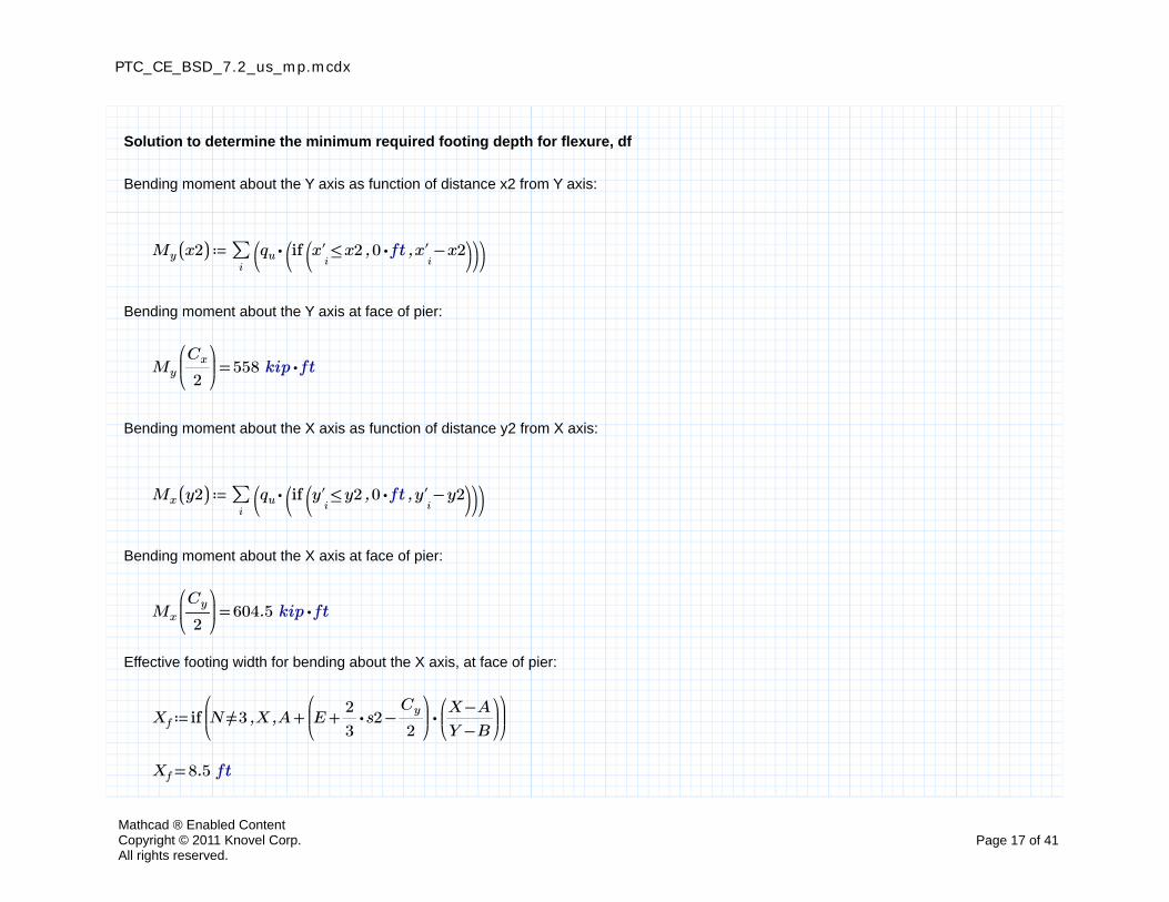
Solution to determine the minimum required footing depth for flexure, df
Bending moment about the Y axis as function of distance x2 from Y axis:
≔My ((x2)) ∑i
⎛⎝
⋅qu ⎛⎝if ⎛
⎝,,≤x'
ix2 ⋅0 ft −x'
ix2⎞
⎠⎞⎠⎞⎠
Bending moment about the Y axis at face of pier:
=My
⎛⎜⎝――Cx
2
⎞⎟⎠
558 ⋅kip ft
Bending moment about the X axis as function of distance y2 from X axis:
≔Mx ((y2)) ∑i
⎛⎝
⋅qu ⎛⎝if ⎛
⎝,,≤y'
iy2 ⋅0 ft −y'
iy2⎞
⎠⎞⎠⎞⎠
Bending moment about the X axis at face of pier:
=Mx
⎛⎜⎝―Cy
2
⎞⎟⎠
604.5 ⋅kip ft
Effective footing width for bending about the X axis, at face of pier:
≔Xf if⎛⎜⎝
,,≠N 3 X +A ⋅⎛⎜⎝
−+E ⋅―2
3s2 ―
Cy
2
⎞⎟⎠
⎛⎜⎝――
−X A
−Y B
⎞⎟⎠
⎞⎟⎠
=Xf 8.5 ft
Mathcad ® Enabled ContentCopyright © 2011 Knovel Corp.All rights reserved.
Page 17 of 41
PTC_CE_BSD_7.2_us_mp.mcdx
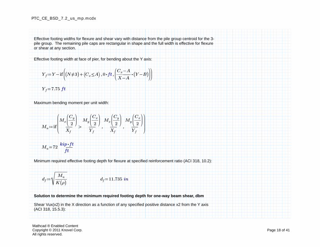
Effective footing widths for flexure and shear vary with distance from the pile group centroid for the 3-pile group. The remaining pile caps are rectangular in shape and the full width is effective for flexure or shear at any section.
Effective footing width at face of pier, for bending about the Y axis:
≔Yf −Y if⎛⎜⎝
,,+(( ≠N 3)) ⎛⎝ ≤Cx A⎞⎠ ⋅0 ft⎛⎜⎝
⋅―――−Cx A
−X A(( −Y B))
⎞⎟⎠
⎞⎟⎠
=Yf 7.75 ft
Maximum bending moment per unit width:
≔Mu if
⎛⎜⎜⎜⎝
,,>―――
Mx
⎛⎜⎝―Cy
2
⎞⎟⎠
Xf
―――
My
⎛⎜⎝――Cx
2
⎞⎟⎠
Yf
―――
Mx
⎛⎜⎝―Cy
2
⎞⎟⎠
Xf
―――
My
⎛⎜⎝――Cx
2
⎞⎟⎠
Yf
⎞⎟⎟⎟⎠
=Mu 72 ―――⋅kip ft
ft
Minimum required effective footing depth for flexure at specified reinforcement ratio (ACI 318, 10.2):
≔df
‾‾‾‾‾――
Mu
K ((ρ))=df 11.735 in
Solution to determine the minimum required footing depth for one-way beam shear, dbm
Shear Vux(x2) in the X direction as a function of any specified positive distance x2 from the Y axis (ACI 318, 15.5.3):
Mathcad ® Enabled ContentCopyright © 2011 Knovel Corp.All rights reserved.
Page 18 of 41
PTC_CE_BSD_7.2_us_mp.mcdx
≔Vux ((x2)) ⋅
⎛⎜⎜⎜⎝
∑i
if
⎛⎜⎜⎜⎝
,,≤x'i
⎛⎜⎝
+――Cx
2―dp
2
⎞⎟⎠
0 if
⎛⎜⎜⎜⎝
,,≥x'i
⎛⎜⎝
+x2 ―dp
2
⎞⎟⎠
1 if
⎛⎜⎜⎜⎝
,,≤x'i
⎛⎜⎝
−x2 ―dp
2
⎞⎟⎠
0 ――――
−+x'i
―dp
2x2
dp
⎞⎟⎟⎟⎠
⎞⎟⎟⎟⎠
⎞⎟⎟⎟⎠
⎞⎟⎟⎟⎠
qu
Shear Vuy(y2) in the Y direction as a function of any specified positive distance y2 from the X axis (ACI 318, 15.5.3):
≔Vuy ((y2)) ⋅
⎛⎜⎜⎜⎝
∑i
if
⎛⎜⎜⎜⎝
,,≤y'i
⎛⎜⎝
+―Cy
2―dp
2
⎞⎟⎠
0 if
⎛⎜⎜⎜⎝
,,≥y'i
⎛⎜⎝
+y2 ―dp
2
⎞⎟⎠
1 if
⎛⎜⎜⎜⎝
,,≤y'i
⎛⎜⎝
−y2 ―dp
2
⎞⎟⎠
0 ――――
−+y'i
―dp
2y2
dp
⎞⎟⎟⎟⎠
⎞⎟⎟⎟⎠
⎞⎟⎟⎟⎠
⎞⎟⎟⎟⎠
qu
Since the 3-pile group is not rectangular the effective width in the X and Y directions varies withdistance from the pile group centroid. The shear must be checked at both the inside edge of the piles and at distance d from the face of the pier.
The following functions are for calculating the effective widths and required depths at any positive distance from the pile group centroid, and the required depths at distance d from the face of the pier. The largest required depth at distance d from the face of pier or at the inside edge of the piles determines the minimum required depth for the 3-pile group.
Effective footing width for one-way shear in the Y direction for the 3-pile group, as a function of any positive distance y2 from the X axis:
≔X3 ((y2)) +A ⋅(( −+E max ((y')) y2))⎛⎜⎝――
−X A
−Y B
⎞⎟⎠
Minimum required depth for one-way shear in the Y direction for the 3-pile group as a function of any positive distance y2 from the X axis:
≔dy3 ((y2)) if⎛⎜⎝
,,≤y2 ―Cy
2⋅0 ft if
⎛⎜⎝
,,<―――――Vuy ((y2))
⋅⋅ϕv vc X3 ((y2))−y2 ―
Cy
2―――――
Vuy ((y2))
⋅⋅ϕv vc X3 ((y2))−y2 ―
Cy
2
⎞⎟⎠
⎞⎟⎠
Mathcad ® Enabled ContentCopyright © 2011 Knovel Corp.All rights reserved.
Page 19 of 41

PTC_CE_BSD_7.2_us_mp.mcdx
Effective footing width for one-way shear in the X direction for the 3-pile group, as a function of any positive distance x2 from the Y axis:
≔Y3 ((x2)) −Y if⎛⎜⎝
,,≤+――Cx
2x2 ―
A
2⋅0 ft ⋅⎛⎝ −+Cx ⋅2 x2 A⎞⎠
⎛⎜⎝――
−Y B
−X A
⎞⎟⎠
⎞⎟⎠
Minimum required depth for one-way shear in the X direction for the 3-pile group as a function of any positive distance x2 from the Y axis:
≔dx3 ((x2)) if⎛⎜⎝
,,≤x2 ――Cx
2⋅0 ft if
⎛⎜⎝
,,<―――――Vux ((x2))
⋅⋅ϕv vc Y3 ((x2))−x2 ――
Cx
2―――――
Vux ((x2))
⋅⋅ϕv vc Y3 ((x2))−x2 ――
Cx
2
⎞⎟⎠
⎞⎟⎠
Minimum required depth for one-way shear in the X direction for the 3-pile group at distance d fromface of pier:
Gue
ss V
alue
sCo
nstr
aint
sSo
lver
≔d 1 ft
≤d +max ((x')) ―dp
2
=――――――
Vux
⎛⎜⎝
+――Cx
2d
⎞⎟⎠
⋅⋅ϕv vc Y3
⎛⎜⎝
+――Cx
2d
⎞⎟⎠
d
≔dx3_d ((d)) Find ((d))
Mathcad ® Enabled ContentCopyright © 2011 Knovel Corp.All rights reserved.
Page 20 of 41

PTC_CE_BSD_7.2_us_mp.mcdx
Minimum required depth for one-way shear in the Y direction for the 3-pile group at distance d fromface of pier:
Gue
ss V
alue
sCo
nstr
aint
sSo
lver
≔d 1 ft
≤d +max ((y')) ―dp
2
=――――――
Vuy
⎛⎜⎝
+―Cy
2d
⎞⎟⎠
⋅⋅ϕv vc X3
⎛⎜⎝
+―Cy
2d
⎞⎟⎠
d
≔dy3_d ((d)) Find ((d))
Mathcad ® Enabled ContentCopyright © 2011 Knovel Corp.All rights reserved.
Page 21 of 41
PTC_CE_BSD_7.2_us_mp.mcdx
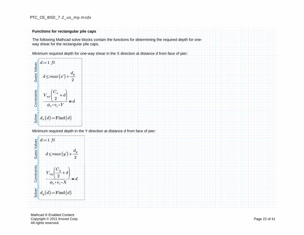
Functions for rectangular pile caps
The following Mathcad solve blocks contain the functions for determining the required depth for one-way shear for the rectangular pile caps.
Minimum required depth for one-way shear in the X direction at distance d from face of pier:
Gue
ss V
alue
sCo
nstr
aint
sSo
lver
≔d 1 ft
≤d +max ((x')) ―dp
2
=――――
Vux
⎛⎜⎝
+――Cx
2d
⎞⎟⎠
⋅⋅ϕv vc Yd
≔dx ((d)) Find ((d))
Minimum required depth in the Y direction at distance d from face of pier:
Gue
ss V
alue
sCo
nstr
aint
sSo
lver
≔d 1 ft
≤d +max ((y')) ―dp
2
=――――
Vuy
⎛⎜⎝
+―Cy
2d
⎞⎟⎠
⋅⋅ϕv vc Xd
≔dy ((d)) Find ((d))
Mathcad ® Enabled ContentCopyright © 2011 Knovel Corp.All rights reserved.
Page 22 of 41
PTC_CE_BSD_7.2_us_mp.mcdx
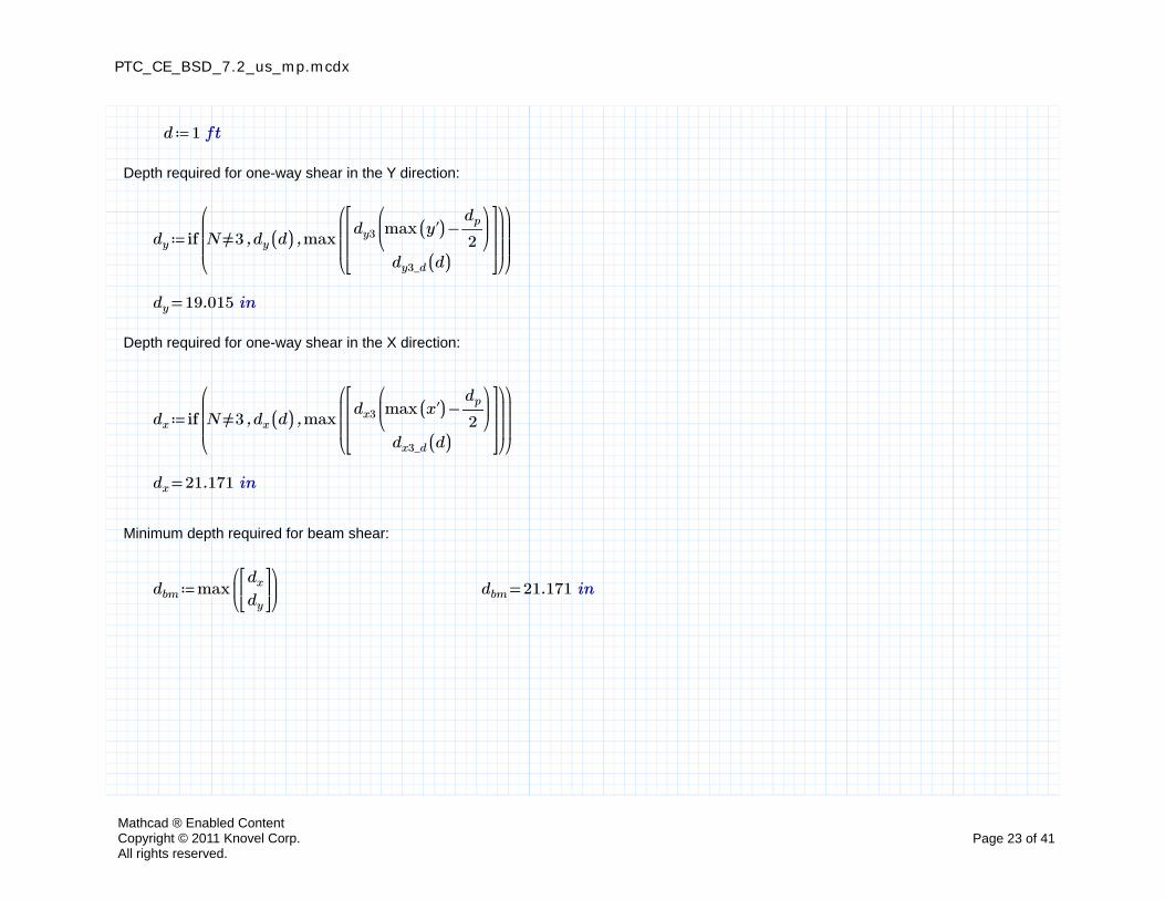
≔d 1 ft
Depth required for one-way shear in the Y direction:
≔dy if
⎛⎜⎜⎜⎝
,,≠N 3 dy ((d)) max
⎛⎜⎜⎜⎝
dy3
⎛⎜⎝
−max ((y')) ―dp
2
⎞⎟⎠
dy3_d ((d))
⎡⎢⎢⎢⎣
⎤⎥⎥⎥⎦
⎞⎟⎟⎟⎠
⎞⎟⎟⎟⎠
=dy 19.015 in
Depth required for one-way shear in the X direction:
≔dx if
⎛⎜⎜⎜⎝
,,≠N 3 dx ((d)) max
⎛⎜⎜⎜⎝
dx3
⎛⎜⎝
−max ((x')) ―dp
2
⎞⎟⎠
dx3_d ((d))
⎡⎢⎢⎢⎣
⎤⎥⎥⎥⎦
⎞⎟⎟⎟⎠
⎞⎟⎟⎟⎠
=dx 21.171 in
Minimum depth required for beam shear:
≔dbm max⎛⎜⎝
dx
dy
⎡⎢⎣
⎤⎥⎦
⎞⎟⎠
=dbm 21.171 in
Mathcad ® Enabled ContentCopyright © 2011 Knovel Corp.All rights reserved.
Page 23 of 41
PTC_CE_BSD_7.2_us_mp.mcdx
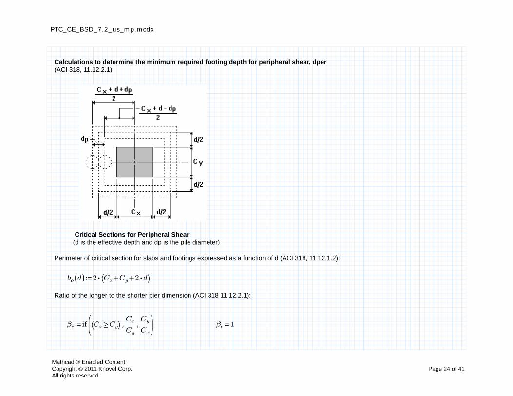
Calculations to determine the minimum required footing depth for peripheral shear, dper(ACI 318, 11.12.2.1)
Critical Sections for Peripheral Shear(d is the effective depth and dp is the pile diameter)
Perimeter of critical section for slabs and footings expressed as a function of d (ACI 318, 11.12.1.2):
≔bo ((d)) ⋅2 ⎛⎝ ++Cx Cy ⋅2 d⎞⎠
Ratio of the longer to the shorter pier dimension (ACI 318 11.12.2.1):
≔βc if⎛⎜⎝
,,⎛⎝ ≥Cx Cy⎞⎠ ――Cx
Cy
――Cy
Cx
⎞⎟⎠
=βc 1
Mathcad ® Enabled ContentCopyright © 2011 Knovel Corp.All rights reserved.
Page 24 of 41
PTC_CE_BSD_7.2_us_mp.mcdx
Nominal "two way" concrete shear strength per unit area in slabs and footings, expressed as a function of effective depth d. Since piers or columns are at the center of the pile cap they are considered "interior" columns for calculating two way shear, and s is equal to 40. (ACI 318 11.12.2.1, Eqs. (11-36), (11-37) and (11-38)):
≔αs 40
≔vcp ((d)) ⋅⋅⋅min
⎛⎜⎜⎜⎜⎜⎜⎝
+2 ―4
βc
――⋅αs d
bo ((d))4
⎡⎢⎢⎢⎢⎢⎣
⎤⎥⎥⎥⎥⎥⎦
⎞⎟⎟⎟⎟⎟⎟⎠
kv
‾‾‾‾‾‾―――f'c_max
psipsi
Function V1(d) computes a vector with elements equal to 0 if the pile produces shear on the critical section and 1 if it does not:
≔V1 ((d))
→―――――――――――
⋅⎛⎜⎝
≤||x'|| ――――−+Cx d dp
2
⎞⎟⎠
⎛⎜⎝
≤||y'|| ――――−+Cy d dp
2
⎞⎟⎠
Function V2(d) computes a vector with elements equal to 1 if the full reaction of the pile producesshear on the critical section and 0 if it does not:
≔V2 ((d))
→―――――――――――――
>+⎛⎜⎝
≥||x'|| ――――++Cx d dp
2
⎞⎟⎠
⎛⎜⎝
≥||y'|| ――――++Cy d dp
2
⎞⎟⎠
0
Function V3(d) computes a vector with elements equal to 1 if a portion of the pile reaction produces shear on the critical section and 0 if it does not:
≔V3 ((d)) −−1 V1 ((d)) V2 ((d))
Mathcad ® Enabled ContentCopyright © 2011 Knovel Corp.All rights reserved.
Page 25 of 41
PTC_CE_BSD_7.2_us_mp.mcdx
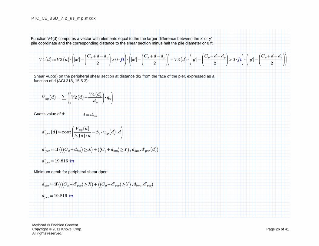
Function V4(d) computes a vector with elements equal to the the larger difference between the x' or y' pile coordinate and the corresponding distance to the shear section minus half the pile diameter or 0 ft.
≔V4 ((d))
→――――――――――――――――――――――――――――――――――
+⋅⋅V3 ((d))⎛⎜⎝
>−||x'||⎛⎜⎝――――
−+Cx d dp
2
⎞⎟⎠
⋅0 ft⎞⎟⎠
⎛⎜⎝
−||x'||⎛⎜⎝――――
−+Cx d dp
2
⎞⎟⎠
⎞⎟⎠
⋅⋅V3 ((d))⎛⎜⎝
>−||y'||⎛⎜⎝――――
−+Cy d dp
2
⎞⎟⎠
⋅0 ft⎞⎟⎠
⎛⎜⎝
−||y'||⎛⎜⎝――――
−+Cy d dp
2
⎞⎟⎠
⎞⎟⎠
Shear Vup(d) on the peripheral shear section at distance d/2 from the face of the pier, expressed as a function of d (ACI 318, 15.5.3):
≔Vup ((d)) ∑⎛⎜⎝
⋅⎛⎜⎝
+V2 ((d)) ―――V4 ((d))
dp
⎞⎟⎠
qu
⎞⎟⎠
Guess value of d: ≔d dbm
≔d'per ((d)) root⎛⎜⎝
,−―――Vup ((d))
⋅bo ((d)) d⋅ϕv vcp ((d)) d
⎞⎟⎠
≔d'per if ⎛⎝ ,,+⎛⎝ ≥⎛⎝ +Cx dbm⎞⎠ X⎞⎠ ⎛⎝ ≥⎛⎝ +Cy dbm⎞⎠ Y⎞⎠ dbm d'per ((d))⎞⎠
=d'per 19.816 in
Minimum depth for peripheral shear dper:
≔dper if ⎛⎝ ,,+⎛⎝ ≥⎛⎝ +Cx d'per⎞⎠ X⎞⎠ ⎛⎝ ≥⎛⎝ +Cy d'per⎞⎠ Y⎞⎠ dbm d'per⎞⎠
=dper 19.816 in
Mathcad ® Enabled ContentCopyright © 2011 Knovel Corp.All rights reserved.
Page 26 of 41
PTC_CE_BSD_7.2_us_mp.mcdx
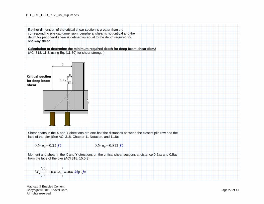
If either dimension of the critical shear section is greater than the corresponding pile cap dimension, peripheral shear is not critical and the depth for peripheral shear is defined as equal to the depth required for one-way shear.
Calculation to determine the minimum required depth for deep beam shear dbm2(ACI 318, 11.8, using Eq. (11-30) for shear strength)
Shear spans in the X and Y directions are one-half the distances between the closest pile row and the face of the pier (See ACI 318, Chapter 11 Notation, and 11.8):
=⋅0.5 ax 0.25 ft =⋅0.5 ay 0.813 ft
Moment and shear in the X and Y directions on the critical shear sections at distance 0.5ax and 0.5ay from the face of the pier (ACI 318, 15.5.3):
=My
⎛⎜⎝
+――Cx
2⋅0.5 ax
⎞⎟⎠
465 ⋅kip ft
Mathcad ® Enabled ContentCopyright © 2011 Knovel Corp.All rights reserved.
Page 27 of 41
PTC_CE_BSD_7.2_us_mp.mcdx
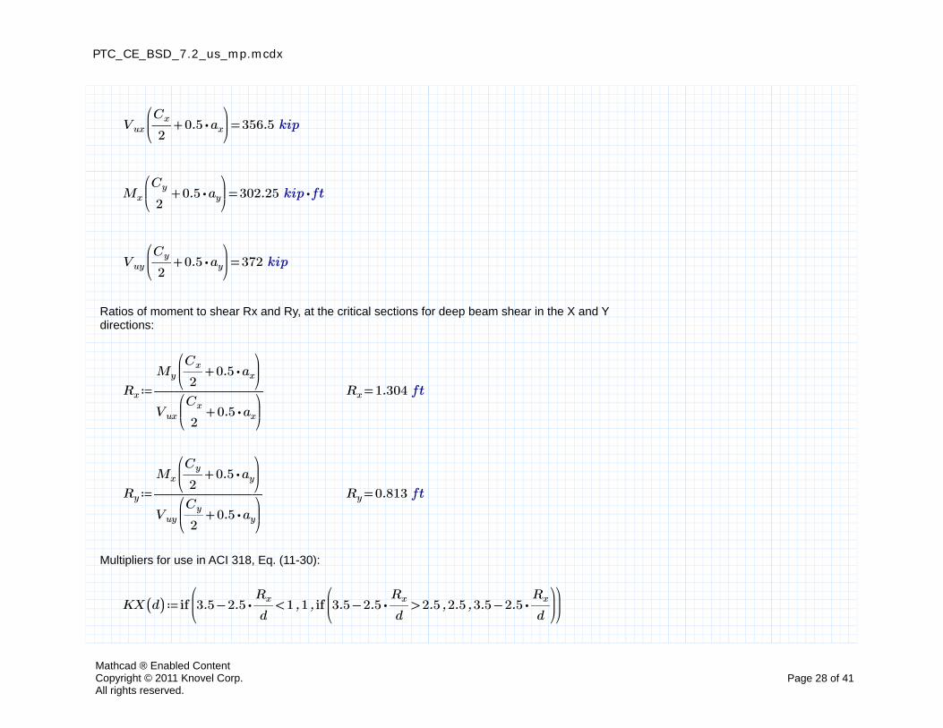
=Vux
⎛⎜⎝
+――Cx
2⋅0.5 ax
⎞⎟⎠
356.5 kip
=Mx
⎛⎜⎝
+―Cy
2⋅0.5 ay
⎞⎟⎠
302.25 ⋅kip ft
=Vuy
⎛⎜⎝
+―Cy
2⋅0.5 ay
⎞⎟⎠
372 kip
Ratios of moment to shear Rx and Ry, at the critical sections for deep beam shear in the X and Y directions:
≔Rx ――――――
My
⎛⎜⎝
+――Cx
2⋅0.5 ax
⎞⎟⎠
Vux
⎛⎜⎝
+――Cx
2⋅0.5 ax
⎞⎟⎠
=Rx 1.304 ft
≔Ry ――――――
Mx
⎛⎜⎝
+―Cy
2⋅0.5 ay
⎞⎟⎠
Vuy
⎛⎜⎝
+―Cy
2⋅0.5 ay
⎞⎟⎠
=Ry 0.813 ft
Multipliers for use in ACI 318, Eq. (11-30):
≔KX ((d)) if⎛⎜⎝
,,<−3.5 ⋅2.5 ―Rx
d1 1 if
⎛⎜⎝
,,>−3.5 ⋅2.5 ―Rx
d2.5 2.5 −3.5 ⋅2.5 ―
Rx
d
⎞⎟⎠
⎞⎟⎠
Mathcad ® Enabled ContentCopyright © 2011 Knovel Corp.All rights reserved.
Page 28 of 41
PTC_CE_BSD_7.2_us_mp.mcdx
≔KY ((d)) if⎛⎜⎝
,,<−3.5 ⋅2.5 ―Ry
d1 1 if
⎛⎜⎝
,,>−3.5 ⋅2.5 ―Ry
d2.5 2.5 −3.5 ⋅2.5 ―
Ry
d
⎞⎟⎠
⎞⎟⎠
Nominal deep beam shear stress at factored load in the X and Y directions (ACI 318, 11.8.7, Eq.(11-30)) with w conservatively assumed equal to minimum temperature reinforcement, temp:
≔vcx ((d)) min
⎛⎜⎜⎜⎜⎜⎝
⋅KX ((d))⎛⎜⎜⎝
⋅⎛⎜⎜⎝
+⋅1.9‾‾‾‾――f'c
psi⋅⋅2500 ρtemp ―
d
Rx
⎞⎟⎟⎠
psi⎞⎟⎟⎠
⋅⋅6‾‾‾‾――f'c
psipsi
⎡⎢⎢⎢⎢⎢⎣
⎤⎥⎥⎥⎥⎥⎦
⎞⎟⎟⎟⎟⎟⎠
≔vcy ((d)) min
⎛⎜⎜⎜⎜⎜⎝
⋅KY ((d))⎛⎜⎜⎝
⋅⎛⎜⎜⎝
+⋅1.9‾‾‾‾――f'c
psi⋅⋅2500 ρtemp ―
d
Ry
⎞⎟⎟⎠
psi⎞⎟⎟⎠
⋅⋅6‾‾‾‾――f'c
psipsi
⎡⎢⎢⎢⎢⎢⎣
⎤⎥⎥⎥⎥⎥⎦
⎞⎟⎟⎟⎟⎟⎠
Effective depth required in the X direction for deep beam shear:
Guess value of d: ≔d dx
≔dbm2_x root
⎛⎜⎜⎜⎜⎝
,−―――――――――――――
Vux
⎛⎜⎝
+――Cx
2⋅0.5 ax
⎞⎟⎠
⋅⋅ϕv vcx ((d)) if⎛⎜⎝
,,≠N 3 Y Y3
⎛⎜⎝
+――Cx
2⋅0.5 ax
⎞⎟⎠
⎞⎟⎠
d d
⎞⎟⎟⎟⎟⎠
=dbm2_x 21.381 in =vcx ⎛⎝dbm2_x⎞⎠ 210.9 psi
Mathcad ® Enabled ContentCopyright © 2011 Knovel Corp.All rights reserved.
Page 29 of 41
PTC_CE_BSD_7.2_us_mp.mcdx
Effective depth required in the Y direction for deep beam shear:
Guess value of d: ≔d dy
≔dbm2_y root
⎛⎜⎜⎜⎜⎝
,−―――――――――――――
Vuy
⎛⎜⎝
+―Cy
2⋅0.5 ay
⎞⎟⎠
⋅⋅ϕv vcy ((d)) if⎛⎜⎝
,,≠N 3 X X3
⎛⎜⎝
+―Cy
2⋅0.5 ay
⎞⎟⎠
⎞⎟⎠
d d
⎞⎟⎟⎟⎟⎠
=dbm2_y 16.556 in =vcy ⎛⎝dbm2_y⎞⎠ 259.2 psi
Depth required for deep beam shear is the larger value of dbm2:
≔dbm2 max⎛⎜⎝
dbm2_x
dbm2_y
⎡⎢⎣
⎤⎥⎦
⎞⎟⎠
=dbm2 21.381 in
Mathcad ® Enabled ContentCopyright © 2011 Knovel Corp.All rights reserved.
Page 30 of 41
PTC_CE_BSD_7.2_us_mp.mcdx
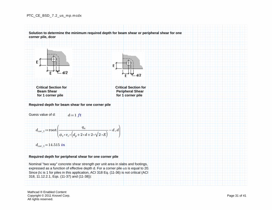
Solution to determine the minimum required depth for beam shear or peripheral shear for one corner pile, dcor
Critical Section for Beam Shearfor 1 corner pile
Critical Section for Peripheral Shearfor 1 corner pile
Required depth for beam shear for one corner pile
Guess value of d: ≔d 1 ft
≔dcor_1 root⎛⎜⎜⎝
,−―――――――――qu
⋅⋅ϕv vc⎛⎝ ++dp ⋅2 d ⋅⋅2 ‾‾2 E
⎞⎠
d d⎞⎟⎟⎠
=dcor_1 14.515 in
Required depth for peripheral shear for one corner pile
Nominal "two way" concrete shear strength per unit area in slabs and footings, expressed as a function of effective depth d. For a corner pile s is equal to 20. Since c is 1 for piles in this application, ACI 318 Eq. (11-36) is not critical (ACI 318, 11.12.2.1, Eqs. (11-37) and (11-38)):
Mathcad ® Enabled ContentCopyright © 2011 Knovel Corp.All rights reserved.
Page 31 of 41
PTC_CE_BSD_7.2_us_mp.mcdx
≔αs 20 ≔bo ((d))⎛⎜⎝
+⋅⎛⎝ +dp d⎞⎠ ―π
4⋅2 E
⎞⎟⎠
≔vcp ((d)) ⋅⋅⋅min
⎛⎜⎜⎜⎝
+――⋅αs d
bo ((d))2
4
⎡⎢⎢⎢⎣
⎤⎥⎥⎥⎦
⎞⎟⎟⎟⎠
kv
‾‾‾‾‾‾―――f'c_max
psipsi
≔dcor_2 root⎛⎜⎝
,−――――――qu
⋅⋅ϕv vcp ((d)) ⎛⎝bo ((d))⎞⎠d d
⎞⎟⎠
=dcor_2 12.507 in
Depth required for one corner pile is the larger value of dcor:
≔dcor max⎛⎜⎝
dcor_1
dcor_2
⎡⎢⎣
⎤⎥⎦
⎞⎟⎠
=dcor 14.515 in
Depth required for a single interior pile, done
Nominal "two way" concrete shear strength per unit area for one interior pile, expressed as a function of effective depth d. For an interior pile s is equal to 40 Since c is 1 for piles in this application ACI 318 Eq. (11-36) is not critical. (ACI 318 11.12.2.1, Eqs. (11-37) and (11-38)):
≔αs 40 ≔bo ((d)) ⋅π ⎛⎝ +dp d⎞⎠
≔vcp ((d)) ⋅⋅⋅min
⎛⎜⎜⎜⎝
+――⋅αs d
bo ((d))2
4
⎡⎢⎢⎢⎣
⎤⎥⎥⎥⎦
⎞⎟⎟⎟⎠
kv
‾‾‾‾‾‾―――f'c_max
psipsi
Mathcad ® Enabled ContentCopyright © 2011 Knovel Corp.All rights reserved.
Page 32 of 41
PTC_CE_BSD_7.2_us_mp.mcdx
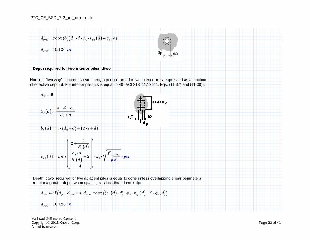
≔done root ⎛⎝ ,−⋅⋅⋅bo ((d)) d ϕv vcp ((d)) qu d⎞⎠
=done 10.126 in
Depth required for two interior piles, dtwo
Nominal "two way" concrete shear strength per unit area for two interior piles, expressed as a function of effective depth d. For interior piles s is equal to 40 (ACI 318, 11.12.2.1, Eqs. (11-37) and (11-38)):
≔αs 40
≔βc ((d)) ―――++s d dp
+dp d
≔bo ((d)) +⋅π ⎛⎝ +dp d⎞⎠ (( +⋅2 s d))
≔vcp ((d)) ⋅⋅⋅min
⎛⎜⎜⎜⎜⎜⎜⎝
+2 ――4
βc ((d))
+――⋅αs d
bo ((d))2
4
⎡⎢⎢⎢⎢⎢⎣
⎤⎥⎥⎥⎥⎥⎦
⎞⎟⎟⎟⎟⎟⎟⎠
kv
‾‾‾‾‾‾―――f'c_max
psipsi
Depth, dtwo, required for two adjacent piles is equal to done unless overlapping shear perimeters require a greater depth when spacing s is less than done + dp:
≔dtwo if ⎛⎝ ,,≤+dp done s done root ⎛⎝ ,−⋅⋅⎛⎝ ⋅bo ((d)) d⎞⎠ ϕv vcp ((d)) ⋅2 qu d⎞⎠⎞⎠
=dtwo 10.126 in
Mathcad ® Enabled ContentCopyright © 2011 Knovel Corp.All rights reserved.
Page 33 of 41
PTC_CE_BSD_7.2_us_mp.mcdx
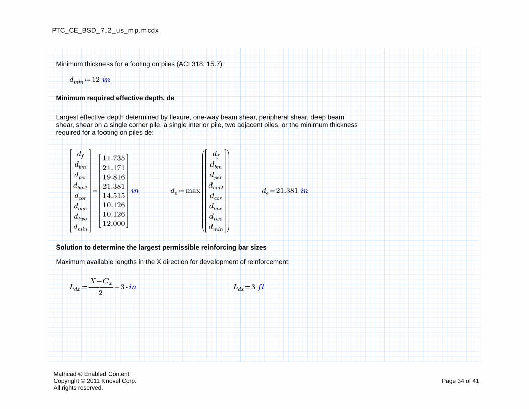
Minimum thickness for a footing on piles (ACI 318, 15.7):
≔dmin 12 in
Minimum required effective depth, de
Largest effective depth determined by flexure, one-way beam shear, peripheral shear, deep beam shear, shear on a single corner pile, a single interior pile, two adjacent piles, or the minimum thickness required for a footing on piles de:
=
df
dbm
dper
dbm2
dcor
done
dtwo
dmin
⎡⎢⎢⎢⎢⎢⎢⎢⎢⎢⎣
⎤⎥⎥⎥⎥⎥⎥⎥⎥⎥⎦
11.73521.17119.81621.38114.51510.12610.12612.000
⎡⎢⎢⎢⎢⎢⎢⎢⎢⎣
⎤⎥⎥⎥⎥⎥⎥⎥⎥⎦
in ≔de max
⎛⎜⎜⎜⎜⎜⎜⎜⎜⎜⎜⎝
df
dbm
dper
dbm2
dcor
done
dtwo
dmin
⎡⎢⎢⎢⎢⎢⎢⎢⎢⎢⎣
⎤⎥⎥⎥⎥⎥⎥⎥⎥⎥⎦
⎞⎟⎟⎟⎟⎟⎟⎟⎟⎟⎟⎠
=de 21.381 in
Solution to determine the largest permissible reinforcing bar sizes
Maximum available lengths in the X direction for development of reinforcement:
≔Ldx −―――−X Cx
2⋅3 in =Ldx 3 ft
Mathcad ® Enabled ContentCopyright © 2011 Knovel Corp.All rights reserved.
Page 34 of 41
PTC_CE_BSD_7.2_us_mp.mcdx
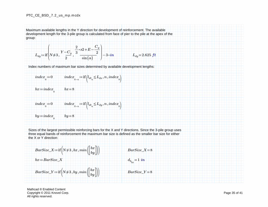
Maximum available lengths in the Y direction for development of reinforcement. The available development length for the 3-pile group is calculated from face of pier to the pile at the apex of the group:
≔Ldy −if
⎛⎜⎜⎜⎝
,,≠N 3 ―――−Y Cy
2―――――
−+⋅―2
3s2 E ―
Cy
2
sin ((α))
⎞⎟⎟⎟⎠
⋅3 in =Ldy 2.625 ft
Index numbers of maximum bar sizes determined by available development lengths:
≔index0
0 ≔index⋅0 n
if ⎛⎜⎝
,,≤ldtnLdx n index
0⎞⎟⎠
≔bx index0
=bx 8
≔index0
0 ≔index⋅0 n
if ⎛⎜⎝
,,≤ldtnLdy n index
0⎞⎟⎠
≔by index0
=by 8
Sizes of the largest permissible reinforcing bars for the X and Y directions. Since the 3-pile group uses three equal bands of reinforcement the maximum bar size is defined as the smaller bar size for either the X or Y direction:
≔BarSize_X if⎛⎜⎝
,,≠N 3 bx min⎛⎜⎝
bxby
⎡⎢⎣
⎤⎥⎦
⎞⎟⎠
⎞⎟⎠
=BarSize_X 8
≔bx BarSize_X =dbbx1 in
≔BarSize_Y if⎛⎜⎝
,,≠N 3 by min⎛⎜⎝
bxby
⎡⎢⎣
⎤⎥⎦
⎞⎟⎠
⎞⎟⎠
=BarSize_Y 8
Mathcad ® Enabled ContentCopyright © 2011 Knovel Corp.All rights reserved.
Page 35 of 41
PTC_CE_BSD_7.2_us_mp.mcdx
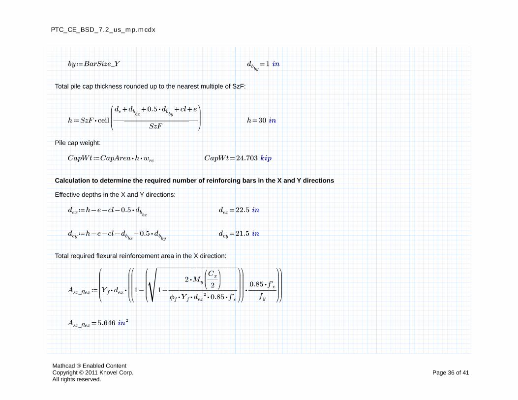
≔by BarSize_Y =dbby1 in
Total pile cap thickness rounded up to the nearest multiple of SzF:
≔h ⋅SzF ceil
⎛⎜⎜⎝――――――――
++++de dbbx⋅0.5 dbby
cl e
SzF
⎞⎟⎟⎠
=h 30 in
Pile cap weight:
≔CapWt ⋅⋅CapArea h wrc =CapWt 24.703 kip
Calculation to determine the required number of reinforcing bars in the X and Y directions
Effective depths in the X and Y directions:
≔dex −−−h e cl ⋅0.5 dbbx=dex 22.5 in
≔dey −−−−h e cl dbbx⋅0.5 dbby
=dey 21.5 in
Total required flexural reinforcement area in the X direction:
≔Asx_flex
⎛⎜⎜⎜⎝
⋅⋅Yf dex
⎛⎜⎜⎜⎝
⋅
⎛⎜⎜⎜⎝
−1
⎛⎜⎜⎜⎝
‾‾‾‾‾‾‾‾‾‾‾‾‾‾‾‾‾‾‾
−1 ―――――――
⋅2 My
⎛⎜⎝――Cx
2
⎞⎟⎠
⋅⋅⋅⋅ϕf Yf dex2 0.85 f'c
⎞⎟⎟⎟⎠
⎞⎟⎟⎟⎠
―――⋅0.85 f'c
fy
⎞⎟⎟⎟⎠
⎞⎟⎟⎟⎠
=Asx_flex 5.646 in2
Mathcad ® Enabled ContentCopyright © 2011 Knovel Corp.All rights reserved.
Page 36 of 41
PTC_CE_BSD_7.2_us_mp.mcdx
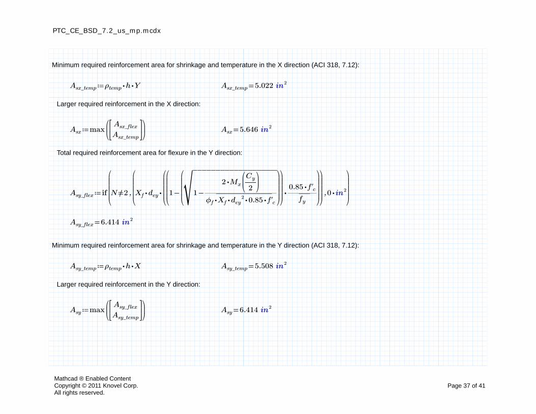
Minimum required reinforcement area for shrinkage and temperature in the X direction (ACI 318, 7.12):
≔Asx_temp ⋅⋅ρtemp h Y =Asx_temp 5.022 in2
Larger required reinforcement in the X direction:
≔Asx max⎛⎜⎝
Asx_flex
Asx_temp
⎡⎢⎣
⎤⎥⎦
⎞⎟⎠
=Asx 5.646 in2
Total required reinforcement area for flexure in the Y direction:
≔Asy_flex if
⎛⎜⎜⎜⎝
,,≠N 2
⎛⎜⎜⎜⎝
⋅⋅Xf dey
⎛⎜⎜⎜⎝
⋅
⎛⎜⎜⎜⎝
−1
⎛⎜⎜⎜⎝
‾‾‾‾‾‾‾‾‾‾‾‾‾‾‾‾‾‾‾
−1 ―――――――
⋅2 Mx
⎛⎜⎝―Cy
2
⎞⎟⎠
⋅⋅⋅⋅ϕf Xf dey2 0.85 f'c
⎞⎟⎟⎟⎠
⎞⎟⎟⎟⎠
―――⋅0.85 f'c
fy
⎞⎟⎟⎟⎠
⎞⎟⎟⎟⎠
⋅0 in2
⎞⎟⎟⎟⎠
=Asy_flex 6.414 in2
Minimum required reinforcement area for shrinkage and temperature in the Y direction (ACI 318, 7.12):
≔Asy_temp ⋅⋅ρtemp h X =Asy_temp 5.508 in2
Larger required reinforcement in the Y direction:
≔Asy max⎛⎜⎝
Asy_flex
Asy_temp
⎡⎢⎣
⎤⎥⎦
⎞⎟⎠
=Asy 6.414 in2
Mathcad ® Enabled ContentCopyright © 2011 Knovel Corp.All rights reserved.
Page 37 of 41
PTC_CE_BSD_7.2_us_mp.mcdx
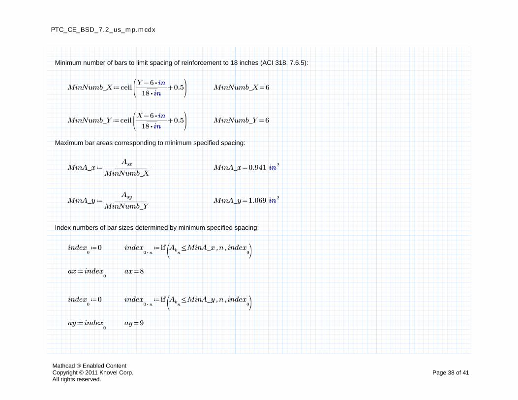
Minimum number of bars to limit spacing of reinforcement to 18 inches (ACI 318, 7.6.5):
≔MinNumb_X ceil⎛⎜⎝
+―――−Y ⋅6 in
⋅18 in0.5
⎞⎟⎠
=MinNumb_X 6
≔MinNumb_Y ceil⎛⎜⎝
+―――−X ⋅6 in
⋅18 in0.5
⎞⎟⎠
=MinNumb_Y 6
Maximum bar areas corresponding to minimum specified spacing:
≔MinA_x ―――――Asx
MinNumb_X=MinA_x 0.941 in2
≔MinA_y ―――――Asy
MinNumb_Y=MinA_y 1.069 in2
Index numbers of bar sizes determined by minimum specified spacing:
≔index0
0 ≔index⋅0 n
if ⎛⎜⎝
,,≤AbnMinA_x n index
0⎞⎟⎠
≔ax index0
=ax 8
≔index0
0 ≔index⋅0 n
if ⎛⎜⎝
,,≤AbnMinA_y n index
0⎞⎟⎠
≔ay index0
=ay 9
Mathcad ® Enabled ContentCopyright © 2011 Knovel Corp.All rights reserved.
Page 38 of 41
PTC_CE_BSD_7.2_us_mp.mcdx
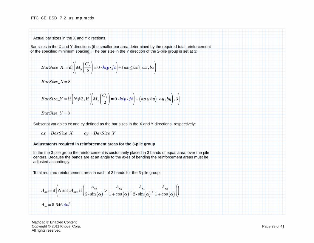
Actual bar sizes in the X and Y directions.
Bar sizes in the X and Y directions (the smaller bar area determined by the required total reinforcement or the specified minimum spacing). The bar size in the Y direction of the 2-pile group is set at 3:
≔BarSixe_X if⎛⎜⎝
,,+⎛⎜⎝
=My
⎛⎜⎝――Cx
2
⎞⎟⎠
⋅⋅0 kip ft⎞⎟⎠
(( ≤ax bx)) ax bx⎞⎟⎠
=BarSixe_X 8
≔BarSize_Y if⎛⎜⎝
,,≠N 2 if⎛⎜⎝
,,+⎛⎜⎝
=Mx
⎛⎜⎝―Cy
2
⎞⎟⎠
⋅⋅0 kip ft⎞⎟⎠
(( ≤ay by)) ay by⎞⎟⎠
3⎞⎟⎠
=BarSize_Y 8
Subscript variables cx and cy defined as the bar sizes in the X and Y directions, respectively:
≔cx BarSize_X ≔cy BarSize_Y
Adjustments required in reinforcement areas for the 3-pile group
In the the 3-pile group the reinforcement is customarily placed in 3 bands of equal area, over the pile centers. Because the bands are at an angle to the axes of bending the reinforcement areas must be adjusted accordingly.
Total required reinforcement area in each of 3 bands for the 3-pile group:
≔Asx if⎛⎜⎝
,,≠N 3 Asx if⎛⎜⎝
,,>―――Asx
⋅2 sin ((α))――――
Asy
+1 cos ((α))―――
Asx
⋅2 sin ((α))――――
Asy
+1 cos ((α))
⎞⎟⎠
⎞⎟⎠
=Asx 5.646 in2
Mathcad ® Enabled ContentCopyright © 2011 Knovel Corp.All rights reserved.
Page 39 of 41
PTC_CE_BSD_7.2_us_mp.mcdx
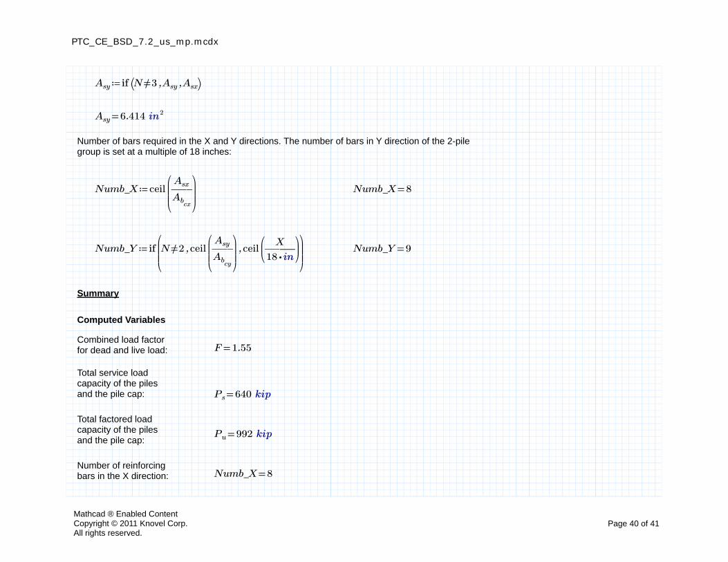
≔Asy if ⎛⎝ ,,≠N 3 Asy Asx⎞⎠
=Asy 6.414 in2
Number of bars required in the X and Y directions. The number of bars in Y direction of the 2-pile group is set at a multiple of 18 inches:
≔Numb_X ceil⎛⎜⎜⎝
――Asx
Abcx
⎞⎟⎟⎠
=Numb_X 8
≔Numb_Y if⎛⎜⎜⎝
,,≠N 2 ceil⎛⎜⎜⎝
――Asy
Abcy
⎞⎟⎟⎠
ceil⎛⎜⎝―――
X
⋅18 in
⎞⎟⎠
⎞⎟⎟⎠
=Numb_Y 9
Summary
Computed Variables
Combined load factor for dead and live load: =F 1.55
Total service load capacity of the pilesand the pile cap: =Ps 640 kip
Total factored load capacity of the piles and the pile cap:
=Pu 992 kip
Number of reinforcing bars in the X direction: =Numb_X 8
Mathcad ® Enabled ContentCopyright © 2011 Knovel Corp.All rights reserved.
Page 40 of 41
PTC_CE_BSD_7.2_us_mp.mcdx
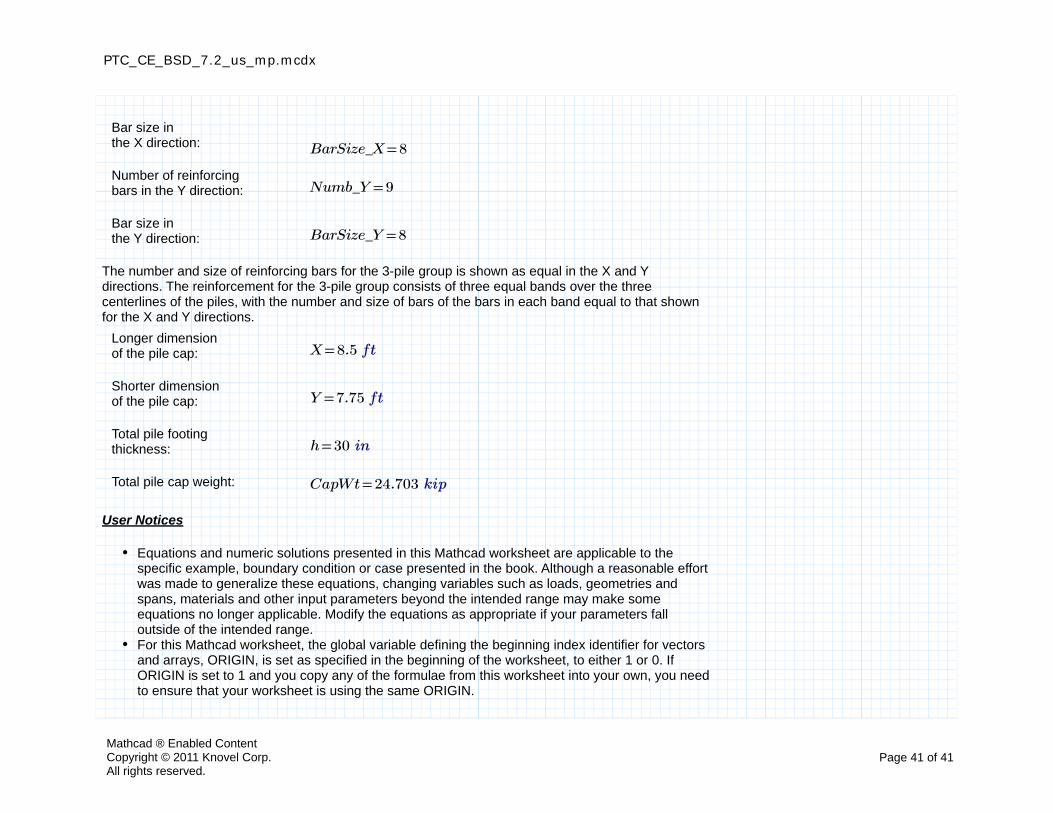
Bar size in the X direction: =BarSize_X 8
Number of reinforcing bars in the Y direction: =Numb_Y 9
Bar size in the Y direction: =BarSize_Y 8
The number and size of reinforcing bars for the 3-pile group is shown as equal in the X and Y directions. The reinforcement for the 3-pile group consists of three equal bands over the three centerlines of the piles, with the number and size of bars of the bars in each band equal to that shown for the X and Y directions.
Longer dimension of the pile cap: =X 8.5 ft
Shorter dimension of the pile cap: =Y 7.75 ft
Total pile footing thickness: =h 30 in
Total pile cap weight: =CapWt 24.703 kip
User Notices
Equations and numeric solutions presented in this Mathcad worksheet are applicable to the specific example, boundary condition or case presented in the book. Although a reasonable effort was made to generalize these equations, changing variables such as loads, geometries and spans, materials and other input parameters beyond the intended range may make some equations no longer applicable. Modify the equations as appropriate if your parameters fall outside of the intended range.For this Mathcad worksheet, the global variable defining the beginning index identifier for vectorsand arrays, ORIGIN, is set as specified in the beginning of the worksheet, to either 1 or 0. If ORIGIN is set to 1 and you copy any of the formulae from this worksheet into your own, you need to ensure that your worksheet is using the same ORIGIN.
Mathcad ® Enabled ContentCopyright © 2011 Knovel Corp.All rights reserved.
Page 41 of 41
![PowerPoint 프레젠테이션 - PEOPLUSpplus.co.kr/wp-content/uploads/2017/01/PEOPLUS-Business... · 2017-01-02 · PTC Creo PDM/PLM PTC Windchill PTC Creo [3D CAD] PTC Creo는제품개발프로세스를자동화하여제품의품질을강화하고제품출시기간을](https://static.fdocuments.in/doc/165x107/5ea311508bf7ce2f923a9163/powerpoint-eoe-2017-01-02-ptc-creo-pdmplm-ptc-windchill-ptc.jpg)