Orientation of a bipolar membrane determines the dominant ...
9
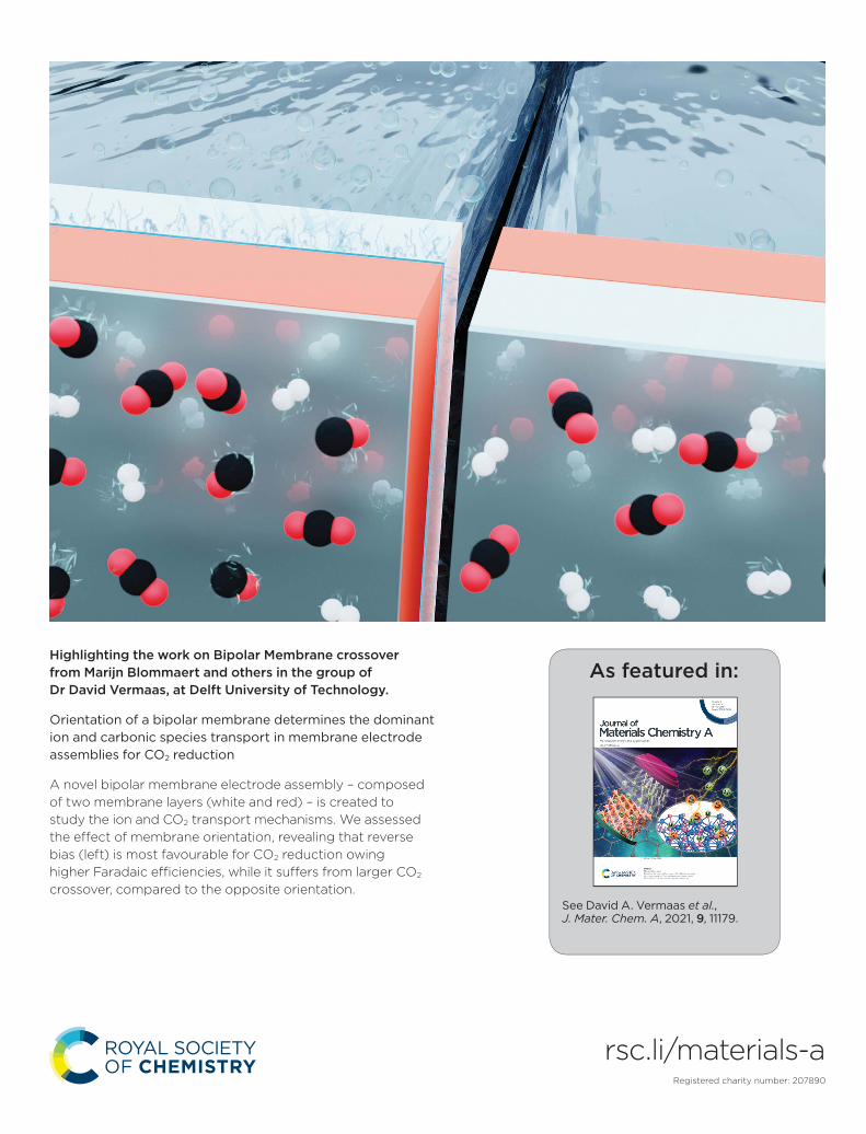
rsc.li/materials-a As featured in: See David A. Vermaas et al. , J. Mater. Chem. A, 2021, 9, 11179. Highlighting the work on Bipolar Membrane crossover from Marijn Blommaert and others in the group of Dr David Vermaas, at Delft University of Technology. Orientation of a bipolar membrane determines the dominant ion and carbonic species transport in membrane electrode assemblies for CO2 reduction A novel bipolar membrane electrode assembly – composed of two membrane layers (white and red) – is created to study the ion and CO2 transport mechanisms. We assessed the effect of membrane orientation, revealing that reverse bias (left) is most favourable for CO2 reduction owing higher Faradaic efficiencies, while it suffers from larger CO2 crossover, compared to the opposite orientation. Registered charity number: 207890
Transcript of Orientation of a bipolar membrane determines the dominant ...
rsc.li/materials-a
As featured in:
See David A. Vermaas et al., J. Mater. Chem. A, 2021, 9, 11179.
Highlighting the work on Bipolar Membrane crossover from Marijn Blommaert and others in the group of Dr David Vermaas, at Delft University of Technology.
Orientation of a bipolar membrane determines the dominant ion and carbonic species transport in membrane electrode assemblies for CO2 reduction
A novel bipolar membrane electrode assembly – composed of two membrane layers (white and red) – is created to study the ion and CO2 transport mechanisms. We assessed the eff ect of membrane orientation, revealing that reverse bias (left) is most favourable for CO2 reduction owing higher Faradaic effi ciencies, while it suff ers from larger CO2 crossover, compared to the opposite orientation.
Registered charity number: 207890
Journal ofMaterials Chemistry A
PAPER
Ope
n A
cces
s A
rtic
le. P
ublis
hed
on 1
1 M
arch
202
1. D
ownl
oade
d on
4/7
/202
2 8:
55:1
7 PM
. T
his
artic
le is
lice
nsed
und
er a
Cre
ativ
e C
omm
ons
Attr
ibut
ion
3.0
Unp
orte
d L
icen
ce.
View Article OnlineView Journal | View Issue
Orientation of a
aDepartment of Chemical Engineering, Del
The Netherlands. E-mail: d.a.vermaas@tudbWetsus, European Centre of Excellence for
Leeuwarden, The Netherlands
† Electronic supplementary informa10.1039/d0ta12398f
Cite this: J. Mater. Chem. A, 2021, 9,11179
Received 22nd December 2020Accepted 11th March 2021
DOI: 10.1039/d0ta12398f
rsc.li/materials-a
This journal is © The Royal Society o
bipolar membrane determines thedominant ion and carbonic species transport inmembrane electrode assemblies for CO2
reduction†
Marijn A. Blommaert, a Rezvan Sharifian,ab Namrata U. Shah, a
Nathan T. Nesbitt, a Wilson A. Smith a and David A. Vermaas *a
A bipolar membrane (BPM), consisting of a cation and an anion exchange layer (CEL and AEL), can be used in
an electrochemical cell in two orientations: reverse bias and forward bias. A reverse bias is traditionally used
to facilitate water dissociation and control the pH at either side. A forward bias has been proposed for
several applications, but insight into the ion transport mechanism is lacking. At the same time, when
implementing a BPM in a membrane electrode assembly (MEA) for CO2 reduction, the BPM orientation
determines the environment of the CO2 reduction catalyst, the anolyte interaction and the direction of
the electric field at the interface layer. In order to understand the transport mechanisms of ions and
carbonic species within a bipolar membrane electrode assembly (BPMEA), these two orientations were
compared by performing CO2 reduction. Here, we present a novel BPMEA using a Ag catalyst layer
directly deposited on the membrane layer at the vapour–liquid interface. In the case of reverse bias, the
main ion transport mechanism is water dissociation. CO2 can easily crossover through the CEL as neutral
carbonic acid due to the low pH in the reverse bias. Once it enters the AEL, it will be transported to the
anolyte as (bi)carbonate because of the presence of hydroxide ions. When the BPM is in the forward bias
mode, with the AEL facing the cathode, no net water dissociation occurs. This not only leads to a 3 V
lower cathodic potential but also reduces the flux of carbonic species through the BPM. As the pH in the
AEL is higher, (bi)carbonate is transported towards the CEL, which then blocks the majority of those
species. However, this forward bias mode showed a lower selectivity towards CO production and
a higher salt concentration was observed at the cathode surface. The high overpotential and CO2
crossover in reverse bias can be mitigated via engineering BPMs, providing higher potential for future
application than that of a BPM in forward bias owing to the intrinsic disadvantages of salt recombination
and poor faradaic efficiency for CO2 reduction.
Introduction
Electrochemical CO2 reduction using renewable energy sources isa key element in closing the carbon cycle while still providingcarbon-based fuels and chemicals.1 The products from this reac-tion are chemical building blocks, which can be used in a widevariety of fuels and plastics. In order to be competitive with currentindustrial technologies, a high selectivity and throughput need tobe achieved. In recent years, the technique of combining anelectrode with a membrane, creating a membrane electrodeassembly (MEA), has led to great improvements in the CO2
University of Technology, 2629 HZ Del,
el.nl
Sustainable Water Technology, 8911 MA
tion (ESI) available. See DOI:
f Chemistry 2021
reduction eld by achieving high selectivity and current densitiesrelevant for industrial application.2–5 MEAs have intrinsic advan-tages to upscale CO2 reduction electrolysers, as they allow opera-tion in a gas–liquid conguration (improving the CO2
concentration and mass transport towards the catalyst) whileensuring product separation. Different types of ion exchangemembranes can be used in such MEA congurations, amongwhich a cation exchangemembrane (CEM)6,7 or an anion exchangemembrane (AEM) are themost used in CO2 electrolyzers.2–5 A thirdtype of membrane used in an MEA is a bipolar membrane (BPM),consisting of a cation and an anion exchange layer (CEL and AEL,respectively) with an internal interface between the two layerswhere a catalyst is deposited to enhance the possible waterdissociation.8–10 In addition to the catalyst at the internal interface,electrolyte composition,11 and pH gradient,12 the two-layerconguration of the BPM allows us to choose the orientation ofthe membrane in an electrochemical cell.
J. Mater. Chem. A, 2021, 9, 11179–11186 | 11179

Journal of Materials Chemistry A Paper
Ope
n A
cces
s A
rtic
le. P
ublis
hed
on 1
1 M
arch
202
1. D
ownl
oade
d on
4/7
/202
2 8:
55:1
7 PM
. T
his
artic
le is
lice
nsed
und
er a
Cre
ativ
e C
omm
ons
Attr
ibut
ion
3.0
Unp
orte
d L
icen
ce.
View Article Online
For a monopolar membrane (e.g., AEM or CEM), the orien-tation of the membrane has no impact on its function. Fora BPM, the orientation of the membrane, determining whichmembrane layer faces the cathode, has great implications for itsion transport mechanism. Two modes of operation are possiblewith a BPM: reverse and forward bias (Fig. 1).
The rst mode of operation is reverse bias with the CELfacing the cathode, where ions are depleted at the internalbipolar membrane interface upon applying a current. To fullthe requirement of a current throughout the cell, ions need tobe formed via the water dissociation reaction (WDR) into H+
and OH� ions.13 This conguration using a BPM provides amplepossibilities in the cell design, since an electrolyte witha different pH can be used at either side; e.g. a near-neutral pHenvironment at the cathode against a high pH at the anode.14
The reverse bias mode is traditionally used in bipolarmembrane electrodialysis (BPMED)15,16 and commonly used forenergy applications (including CO2 reduction and water split-ting)14,17 and resource recovery.18 Li et al. demonstrated betterstability when sandwiching a BPM between gas diffusion elec-trodes (GDEs), compared to monopolar membranes, at variouscurrent densities.8 Salvatore et al. reached a faradaic efficiency(FE) of 50% at 200 mA cm�2 with a liquid support layer ofNaHCO3 between the BPM and GDE.9 However, in neutral pH,the overpotential of the WDR increases signicantly. On theother hand, when the cathodic catalyst layer is attached to theCEL of the BPM directly in an MEA conguration, an acidicenvironment surrounds the catalyst, possibly favouring theunwanted hydrogen evolution reaction.
The second operating mode is forward bias with the AELfacing the cathode, where ions are transported towards theinterface where recombination or precipitation can occur.19 Inthe forward bias mode, water is being formed at the interfacelayer, which can cause blistering.20,21 This conguration wasproposed for CO2 reduction10 to leverage the recent achieve-ments in AEM-based MEAs.22,23 Although ions may accumulateat the BPM interface layer,24,25 the cathode–AEL environmentcould be combined with a low membrane overpotential in theforward bias mode. Patru et al. demonstrated a forward biassystem (vapour–vapour) reaching a FE towards CO of 13% at 50mA cm�2 while inhibiting CO2 crossover to the anode.10 Thisunwanted crossover of CO2 (and its negatively charged dissolvedspecies, CO3
2� and HCO3�, or carbonic acid, H2CO3, which are
all grouped under the term dissolved inorganic carbon, DIC)compromises the efficiency of CO2 electrolyzers and is a well-known problem, especially in AEM-based MEA congurations.26
Fig. 1 Modes of operation of a BPM, consisting of a cation exchangelayer (CEL) and an anion exchange layer (AEL): (a) reverse bias and (b)forward bias.
11180 | J. Mater. Chem. A, 2021, 9, 11179–11186
In general, both biases of a BPM showed stability in the orderof a few hours. For developing BPM-based CO2 electrolyzers,long term stability and therefore low ion and product crossoverthrough the membrane are essential. In order to achieve longterm stability for both BPM orientations in an MEA-based CO2
electrolyzer, knowledge of the ion transport is needed, which iscurrently lacking in a vapour–liquid environment. In particular,little is published on the transport mechanisms in the forwardbias mode. In this study, we reveal the ion transport mecha-nisms and practical feasibility of a BPM in reverse bias andforward bias embedded in an MEA for CO2 electrolysis.
Results and discussion
To study the different transport mechanisms of ions andcarbonic species within a BPM-based MEA (BPMEA), weexamine two cases for CO2 electrolysis, one case using a BPM inreverse bias and another case in forward bias. In order topreferentially make gaseous products, Ag was used as a catalystwhich was directly sputtered onto the membrane. Ag has shownthe ability to reduce CO2 to CO and H2 with different productratios depending on the applied potential, electrolyte, and pH.1
The use of a catalytic layer deposited directly on the membrane,in the absence of a carbon based porous diffusion layer, allowsthe ability to observe the possible salt formation (i.e., occurringdue to transportation of the electrolyte ions through the BPMtowards the catalyst). To achieve a direct deposition on themembrane via sputtering in a vacuum, and to avoid structuralchanges in the membrane moiety, which would occur ifabsorbed water vaporizes, a heterogeneous Ralex® bipolarmembrane was used in its dry state as the catalyst support.During the sputtering process, the BPM was de-aerated,creating micro-cracks which facilitate the crossover of CO2
(see later). A description of the fabrication process can be foundin the ESI.†
A diagram of the BPMEA in reverse bias mode is illustratedin Fig. 2a. Upon applying a current, water is dissociated intoprotons (H+) and hydroxide ions (OH�) in between the CEL andAEL. OH� will then transport through the AEL into the elec-trolyte to replenish the consumed hydroxide ions at the Ptanode (resulting in the oxygen evolution reaction). For theforward bias mode (Fig. 2b), the Ag catalyst was deposited onthe AEL, where anions (e.g., (bi)carbonate) migrate towards theinterface with the CEL. Similarly, cations migrate in the CEL inthe opposite direction. Hence, the hypothesis for the forwardbias is that no ion depletion occurs at the internal BPM inter-face and therefore no net WDR is expected, but salt accumula-tion occurs instead. The implications of each of these twodifferent charge transport mechanisms will be discussed in thefollowing sections.
The selectivity of the cathodic reaction in our MEA vapour–liquid conguration depends on the orientation of the bipolarmembrane. The reverse bias demonstrates a stable COproduction (60% FE) for one hour of operation as shown inFig. 2c, aer an initial stabilisation period where more H2 wasproduced. With an opposite membrane orientation (forwardbias mode), a signicantly lower selectivity was obtained:
This journal is © The Royal Society of Chemistry 2021
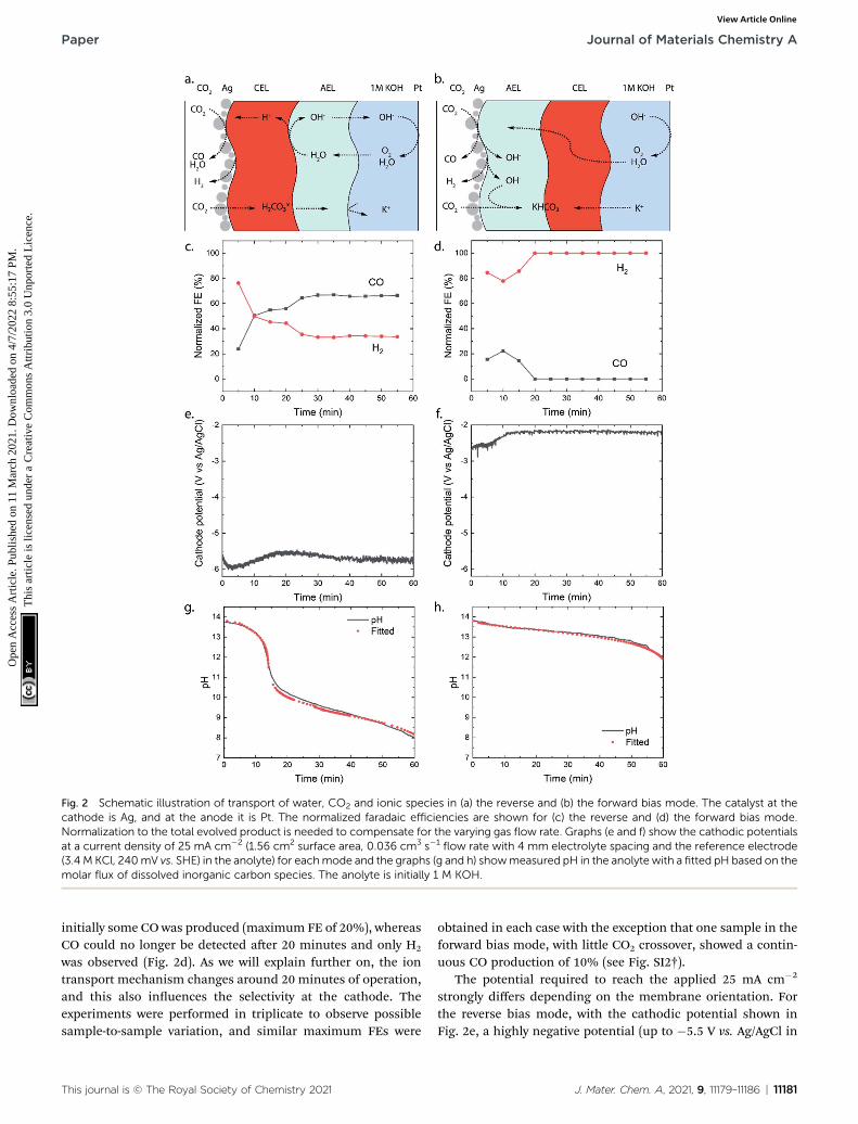
Fig. 2 Schematic illustration of transport of water, CO2 and ionic species in (a) the reverse and (b) the forward bias mode. The catalyst at thecathode is Ag, and at the anode it is Pt. The normalized faradaic efficiencies are shown for (c) the reverse and (d) the forward bias mode.Normalization to the total evolved product is needed to compensate for the varying gas flow rate. Graphs (e and f) show the cathodic potentialsat a current density of 25 mA cm�2 (1.56 cm2 surface area, 0.036 cm3 s�1
flow rate with 4 mm electrolyte spacing and the reference electrode(3.4 M KCl, 240mV vs. SHE) in the anolyte) for eachmode and the graphs (g and h) showmeasured pH in the anolyte with a fitted pH based on themolar flux of dissolved inorganic carbon species. The anolyte is initially 1 M KOH.
Paper Journal of Materials Chemistry A
Ope
n A
cces
s A
rtic
le. P
ublis
hed
on 1
1 M
arch
202
1. D
ownl
oade
d on
4/7
/202
2 8:
55:1
7 PM
. T
his
artic
le is
lice
nsed
und
er a
Cre
ativ
e C
omm
ons
Attr
ibut
ion
3.0
Unp
orte
d L
icen
ce.
View Article Online
initially some CO was produced (maximum FE of 20%), whereasCO could no longer be detected aer 20 minutes and only H2
was observed (Fig. 2d). As we will explain further on, the iontransport mechanism changes around 20 minutes of operation,and this also inuences the selectivity at the cathode. Theexperiments were performed in triplicate to observe possiblesample-to-sample variation, and similar maximum FEs were
This journal is © The Royal Society of Chemistry 2021
obtained in each case with the exception that one sample in theforward bias mode, with little CO2 crossover, showed a contin-uous CO production of 10% (see Fig. SI2†).
The potential required to reach the applied 25 mA cm�2
strongly differs depending on the membrane orientation. Forthe reverse bias mode, with the cathodic potential shown inFig. 2e, a highly negative potential (up to �5.5 V vs. Ag/AgCl in
J. Mater. Chem. A, 2021, 9, 11179–11186 | 11181

Journal of Materials Chemistry A Paper
Ope
n A
cces
s A
rtic
le. P
ublis
hed
on 1
1 M
arch
202
1. D
ownl
oade
d on
4/7
/202
2 8:
55:1
7 PM
. T
his
artic
le is
lice
nsed
und
er a
Cre
ativ
e C
omm
ons
Attr
ibut
ion
3.0
Unp
orte
d L
icen
ce.
View Article Online
the anolyte) was needed to perform the cathodic reactions,while for the forward bias mode a cathodic potential of around�2.0 V vs. Ag/AgCl was required to achieve the same currentdensity (Fig. 2f). Themajor difference can be explained from theprocesses in the interfacial layer between the CEL and AEL. Themain energy loss in the reverse bias mode appears to be asso-ciated with the WDR, shown by the membrane voltage differ-ence of 2.3 V at 25 mA cm�2, when reverse bias is appliedcompared to forward bias (see Fig. 3a). In addition, theimpedance of the BPM measured in each orientation supportsthe hypothesis that the WDR is (almost completely) absent inforward bias: the peak related to the WDR disappears incomparison to reverse bias (see Fig. 3b).13 The voltage requiredto drive the WDR indicates that the catalyst at the internalinterface is kinetically slow. Because our membrane was chosento allow synthesis in a dry state, this particular commercial BPMis not optimized for CO2 reduction in this conguration. Recentliterature has shown via experimental work27–29 and simula-tions30,31 that the catalyst overpotential can be easily reduced bytwo orders of magnitude at these current densities compared tothe one that was used for these studies. Hence, the cathodepotentials in Fig. 2e and f are expected much closer to theirthermodynamic equivalent in an optimized BPMEA system.
As no net WDR occurs in the forward bias mode and iontransport is directed towards the internal interface, ions canneutralize in the BPM. The type of neutralization differsdepending on the type of ion, e.g. protons and hydroxide ionswill perform water association and allow harvesting a signi-cant membrane voltage due to the high gradients in the H+/OH�
concentration over the CEL/AEL interface, leveraged in BPM-based batteries.16,32 However, only limited protons are presentin the CEL in the forward bias mode, and K+ is present inabundance instead (as the anolyte is chosen to be KOH). In thecase of such alkaline CO2 electrolysis, K+ will neutralize theanions (i.e., the carbonate ions entering the AEL from the gasside) at the internal interface, which will in theory generatea relatively small potential drop of 59.1 mV for every order ofmagnitude difference in the concentration across the interface.Based on the work of Strathmann and co-workers, the concen-tration in the membrane layers was found to be a function ofthe charge density of the BPM (which is experimentally
Fig. 3 (a) Linear sweep potentiometry at 0.5 mA s�1 in 1 M NaCl (correcreverse bias and negative forward bias; values at 25 mA cm�2 are 2.74 Vcm�2 with 6.4 mA cm�2 amplitude.
11182 | J. Mater. Chem. A, 2021, 9, 11179–11186
determined to be 3.2 M, see the ESI†) and the concentration ofions in the electrolyte.33 The potential drop can then be calcu-lated based on the concentration of K+ in the CEL (3.5 M) and inthe AEL (0.3 M), resulting in a potential drop of 64 mV. This saltneutralization would imply a reduced cell voltage, also indi-cated by the negative membrane voltage at low current densityin forward bias (Fig. 3a).
Although carbonate species may be the dominant chargecarriers through the BPM layers, the crossover of CO2 seems tobe lower in the forward bias than in the reverse bias, derivedfrom the pH of the anolyte, as illustrated in Fig. 2g and h.Initially, the OH� is consumed to turn CO2 into CO3
2� (viaHCO3
�) as shown in eqn (1) and (2).
CO2 + OH� / HCO3�, pKa ¼ 6.3 (1)
HCO3� + OH� / CO3
2� + H2O, pKa ¼ 10.3 (2)
Once the pH of the anolyte decreases below the pKa shown ineqn (2), aer approximately 15 minutes, only the reactionshown in eqn (1) will proceed in the right hand direction, whilethe reaction shown in eqn (2) is reversed since the equilibriumconditions change.
Eqn (1) and (2) allow estimation of the CO2 crossover fromthe experimentally observed change in pH for each mode.Chemical equilibrium soware, Visual MINTEQ, was used to tthe molar ux of carbonic species through the entire BPM. Aconstant ux did not give a good t with the experimentalmeasurements, which seems reasonable since the conditions inthe cell change over time as the carbonic species get absorbedby the KOH anolyte. The gradual build-up of DIC in the anolyteleads to a lower concentration gradient over the BPM, whichlowers the DIC ux over time (see Fig. SI3†).
For the reverse bias mode, a rapid pH change is observedduring the experiment as a pH of 8.0 is reached aer 60minutes. The forward bias mode reaches a pH of 12.0 aer only60 minutes, indicating that the OH� is consumed at a rateapproximately 5� slower than that in the reverse bias. It isimportant to note that in the forward bias mode no net WDRoccurs and therefore no replenishment of consumed OH� ions
ted for electrolyte losses) with positive membrane potential indicating(reverse) and 0.41 V (forward). (b) Galvanostatic impedance at 25 mA
This journal is © The Royal Society of Chemistry 2021
Paper Journal of Materials Chemistry A
Ope
n A
cces
s A
rtic
le. P
ublis
hed
on 1
1 M
arch
202
1. D
ownl
oade
d on
4/7
/202
2 8:
55:1
7 PM
. T
his
artic
le is
lice
nsed
und
er a
Cre
ativ
e C
omm
ons
Attr
ibut
ion
3.0
Unp
orte
d L
icen
ce.
View Article Online
at the anode takes place. The consumption of OH� at the anodeaccounts for 15% of the OH� loss.
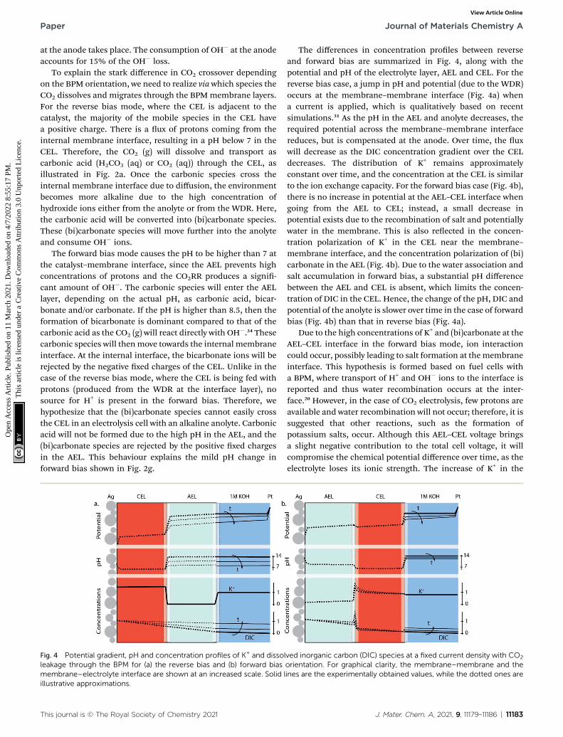
To explain the stark difference in CO2 crossover dependingon the BPM orientation, we need to realize via which species theCO2 dissolves and migrates through the BPMmembrane layers.For the reverse bias mode, where the CEL is adjacent to thecatalyst, the majority of the mobile species in the CEL havea positive charge. There is a ux of protons coming from theinternal membrane interface, resulting in a pH below 7 in theCEL. Therefore, the CO2 (g) will dissolve and transport ascarbonic acid (H2CO3 (aq) or CO2 (aq)) through the CEL, asillustrated in Fig. 2a. Once the carbonic species cross theinternal membrane interface due to diffusion, the environmentbecomes more alkaline due to the high concentration ofhydroxide ions either from the anolyte or from the WDR. Here,the carbonic acid will be converted into (bi)carbonate species.These (bi)carbonate species will move further into the anolyteand consume OH� ions.
The forward bias mode causes the pH to be higher than 7 atthe catalyst–membrane interface, since the AEL prevents highconcentrations of protons and the CO2RR produces a signi-cant amount of OH�. The carbonic species will enter the AELlayer, depending on the actual pH, as carbonic acid, bicar-bonate and/or carbonate. If the pH is higher than 8.5, then theformation of bicarbonate is dominant compared to that of thecarbonic acid as the CO2 (g) will react directly with OH�.34 Thesecarbonic species will thenmove towards the internal membraneinterface. At the internal interface, the bicarbonate ions will berejected by the negative xed charges of the CEL. Unlike in thecase of the reverse bias mode, where the CEL is being fed withprotons (produced from the WDR at the interface layer), nosource for H+ is present in the forward bias. Therefore, wehypothesize that the (bi)carbonate species cannot easily crossthe CEL in an electrolysis cell with an alkaline anolyte. Carbonicacid will not be formed due to the high pH in the AEL, and the(bi)carbonate species are rejected by the positive xed chargesin the AEL. This behaviour explains the mild pH change inforward bias shown in Fig. 2g.
Fig. 4 Potential gradient, pH and concentration profiles of K+ and dissolleakage through the BPM for (a) the reverse bias and (b) forward biasmembrane–electrolyte interface are shown at an increased scale. Solid lillustrative approximations.
This journal is © The Royal Society of Chemistry 2021
The differences in concentration proles between reverseand forward bias are summarized in Fig. 4, along with thepotential and pH of the electrolyte layer, AEL and CEL. For thereverse bias case, a jump in pH and potential (due to the WDR)occurs at the membrane–membrane interface (Fig. 4a) whena current is applied, which is qualitatively based on recentsimulations.31 As the pH in the AEL and anolyte decreases, therequired potential across the membrane–membrane interfacereduces, but is compensated at the anode. Over time, the uxwill decrease as the DIC concentration gradient over the CELdecreases. The distribution of K+ remains approximatelyconstant over time, and the concentration at the CEL is similarto the ion exchange capacity. For the forward bias case (Fig. 4b),there is no increase in potential at the AEL–CEL interface whengoing from the AEL to CEL; instead, a small decrease inpotential exists due to the recombination of salt and potentiallywater in the membrane. This is also reected in the concen-tration polarization of K+ in the CEL near the membrane–membrane interface, and the concentration polarization of (bi)carbonate in the AEL (Fig. 4b). Due to the water association andsalt accumulation in forward bias, a substantial pH differencebetween the AEL and CEL is absent, which limits the concen-tration of DIC in the CEL. Hence, the change of the pH, DIC andpotential of the anolyte is slower over time in the case of forwardbias (Fig. 4b) than that in reverse bias (Fig. 4a).
Due to the high concentrations of K+ and (bi)carbonate at theAEL–CEL interface in the forward bias mode, ion interactioncould occur, possibly leading to salt formation at the membraneinterface. This hypothesis is formed based on fuel cells witha BPM, where transport of H+ and OH� ions to the interface isreported and thus water recombination occurs at the inter-face.20 However, in the case of CO2 electrolysis, few protons areavailable and water recombination will not occur; therefore, it issuggested that other reactions, such as the formation ofpotassium salts, occur. Although this AEL–CEL voltage bringsa slight negative contribution to the total cell voltage, it willcompromise the chemical potential difference over time, as theelectrolyte loses its ionic strength. The increase of K+ in the
ved inorganic carbon (DIC) species at a fixed current density with CO2
orientation. For graphical clarity, the membrane–membrane and theines are the experimentally obtained values, while the dotted ones are
J. Mater. Chem. A, 2021, 9, 11179–11186 | 11183
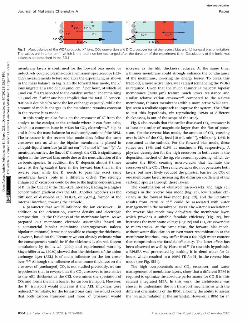
Fig. 5 Mass balance of the WDR products, K+ ions, CO2 conversion and DIC crossover for (a) the reverse bias and (b) forward bias orientation.The values are in mmol cm�2 which is the total number exchanged after the duration of the experiment (1 h). Calculations of the ionic molbalances are described in the ESI.†
Journal of Materials Chemistry A Paper
Ope
n A
cces
s A
rtic
le. P
ublis
hed
on 1
1 M
arch
202
1. D
ownl
oade
d on
4/7
/202
2 8:
55:1
7 PM
. T
his
artic
le is
lice
nsed
und
er a
Cre
ativ
e C
omm
ons
Attr
ibut
ion
3.0
Unp
orte
d L
icen
ce.
View Article Online
membrane layers is conrmed for the forward bias mode viainductively coupled plasma-optical emission spectroscopy (ICP-OES) measurements before and aer the experiment, as shownin the mass balance in Fig. 5. In the forward bias mode, the K+
ions migrate at a rate of 130 mmol cm�2 per hour, of which 80mmol cm�2 is transported to the catalyst surface. The remaining50 mmol cm�2 aer one hour implies that the total K+ concen-tration is doubled (to twice the ion exchange capacity), while theamount of mobile charges in the membrane remains constantin the reverse bias mode.
In this study we also focus on the crossover of K+ from theanolyte to the catalyst at the cathode where it can form salts,which is a common issue in MEAs for CO2 electrolysis.35 Fig. 5aand b show themass balance for each conguration of the BPM.The crossover in the reverse bias mode does follow the samecrossover rate as when the bipolar membrane is placed ina liquid–liquid interface (at 25 mA cm�2, 7 mmol h�1 cm�2).11 Asmentioned earlier, the ux of K+ through the CEL is signicantlyhigher in the forward bias mode due to the neutralization of thecarbonic species. In addition, the K+ deposits almost 8 timesfaster at the Ag catalyst layer in the forward bias than in thereverse bias, while the K+ needs to pass the exact samemembrane layers (only in a different order). The stronglyenhanced K+ crossover could be due to the higher concentrationof K+ in the CEL near the CEL–AEL interface, leading to a higherconcentration gradient over the AEL. Another hypothesis is thediffusion of dissolved salt (KHCO3 or K2CO3), formed at theinternal interface, towards the cathode.
A parameter that would inuence the ion crossover – inaddition to the orientation, current density and electrolytecomposition – is the thickness of the membrane layers. As weprepared our membrane electrode assemblies based ona commercial bipolar membrane (heterogeneous Ralex®bipolar membrane), it was not possible to change the thickness.However, based on the literature we can already estimate whatthe consequences would be if the thickness is altered. Recentsimulations by Bui et al. (2020) and experimental work byMayerhofer et al. (2020) showed that the thickness of the anionexchange layer (AEL) is of main inuence on the ion cross-over.31,36 Although the inuence of membrane thickness on thecrossover of (uncharged) CO2 is not studied previously, we canhypothesize that in reverse bias the CO2 crossover is insensitiveto the AEL thickness as the CEL determines the speciation ofCO2 and forms the main barrier for carbon transport. However,the K+ transport would increase if the AEL thickness werereduced.31 Similarly, for the forward bias case, we would expectthat both carbon transport and more K+ crossover would
11184 | J. Mater. Chem. A, 2021, 9, 11179–11186
increase as the AEL thickness reduces. At the same time,a thinner membrane could strongly enhance the conductanceof the membrane, lowering the energy losses. To break thistrade-off, a more active interlayer catalyst (enhancing the WDR)is required. Given that the much thinner FumaSep® bipolarmembranes (<200 mm) feature much lower resistance andsimilar relative cation crossover11 compared to the Ralex®membrane, thinner membranes with a more active WDR cata-lyst seem a realistic approach to improve the system. The effortto test this hypothesis, via reproducing BPMs at differentthicknesses, is out of the scope of the study.
Fig. 5 also reveals that the earlier discussed CO2 crossover isat least one order of magnitude larger than the ux of potas-sium. For the reverse bias mode, the amount of CO2 crossingover is 36% of the CO2 feed (10 mL min�1), while only 1.6% isconsumed at the cathode. For the forward bias mode, thesevalues are 18% and 0.3% at maximum FE, respectively. Aphysical description for the high crossover in both cases is thedeposition method of the Ag, via vacuum sputtering, which de-aerates the BPM, creating micro-cracks that facilitate thecrossover of the CO2. These micro-cracks did not penetrate bothlayers, but most likely reduced the physical barrier for CO2 ofone membrane layer, increasing the diffusion coefficient of thecarbonic species through these layers.
The combination of observed micro-cracks and high cellvoltages in the reverse bias mode (Fig. 2e), low faradaic effi-ciency in the forward bias mode (Fig. 2d), and the literatureresults from Patru et al.10 could be associated with watermanagement in the membrane layers. The water dissociation inthe reverse bias mode may dehydrate the membrane layer,which provides a suitable faradaic efficiency (Fig. 2c), butincreases the membrane voltage (Fig. 2e) and CO2 crossover dueto micro-cracks. At the same time, the forward bias mode,without water dissociation or even water recombination at themembrane interface, may suffer from a too high water contentthat compromises the faradaic efficiency. The latter effect hasbeen observed as well by Patru et al.10 To test this hypothesis,a BPMEA was pre-treated by soaking it in demi water for 24hours, which resulted in a 100% FE for H2 in the reverse biasmode (see Fig. SI5†).
The high overpotentials and CO2 crossover, and watermanagement of membrane layers, show that a different BPM isrequired to optimize the absolute performance for CO2R in thiscatalyst integrated MEA. In this work, the architecture waschosen to understand the ion transport mechanisms with thedifferent orientations of the BPM, allowing the ability to assessthe ion accumulation at the surface(s). However, a BPM for an
This journal is © The Royal Society of Chemistry 2021

Paper Journal of Materials Chemistry A
Ope
n A
cces
s A
rtic
le. P
ublis
hed
on 1
1 M
arch
202
1. D
ownl
oade
d on
4/7
/202
2 8:
55:1
7 PM
. T
his
artic
le is
lice
nsed
und
er a
Cre
ativ
e C
omm
ons
Attr
ibut
ion
3.0
Unp
orte
d L
icen
ce.
View Article Online
MEA in practical CO2 electrolysis should possess a highercatalytic energy efficiency and ionic conductance. Also for thedeposition method, spray deposition could be used as a lessdestructive technique than the vacuum sputtering used in thisstudy. The spray deposition oen requires a conductivesupport, such as a gas diffusion electrode. Considering sucha practical architecture, the salt formation that was observed inthe forward bias mode can facilitate ooding when used incombination with a gas diffusion electrode, impacting theperformance of the system.35 In general, forward bias operationhas intrinsic instability issues in terms of salt accumulation,which limits the operational lifetime of the BPM from hours todays.10 Reverse bias operation suffers from signicant CO2
crossover and requires a very high membrane voltage (seeFig. SI4†), but these aspects can be tuned by engineering morerobust, thin membrane layers and better WDR catalysts foroptimized CO2 electrolyzers. Furthermore, despite the acidicconditions of the cathode in reverse bias, the faradaic efficiencyfor CO is still considerably higher than that in the forward biasmode, even when the catalyst is sputtered directly on the(acidic) CEL.
Conclusions
We have studied the transport mechanisms of ions and (bothcharged and neutral) carbonic species as a function of theorientation of a bipolar membrane within a MEA performingelectrochemical CO2 reduction. A BPM-based MEA with thereverse bias orientation was compared to the opposite orienta-tion, forward bias. Both orientations had a vapour–liquid cellconguration where a CO2R catalyst (Ag) was directly depositedon the membrane interface. For the reverse bias mode, wherethe cation exchange layer of the BPM is in contact with thecatalyst, the dominant ion transport mechanism is waterdissociation that occurs at the internal membrane interface. Atthe same time, CO2 crosses over through the BPM, starting byentering the CEL as carbonic acid (due to the low pH in the CEL)and being transported through the AEL towards the Pt anode as(bi)carbonate. The molar ux of CO2 that crosses over throughthe BPM decreases over time due to the reduction in the dis-solved inorganic carbon (DIC) concentration gradient.
For the case where the BPM is placed in the forward biasorientation (i.e., the CEL facing the anode), no water dissocia-tion reaction occurs, saving 3 V in the cathodic potential at 25mA cm�2 compared to the reverse bias mode. The molar ux ofcarbonic species is half of that in the reverse bias mode and hasa similar decreasing trend over time. Aer 10 minutes of oper-ation, a reduction in the absolute cathodic potential is observedwhich coincided with a decreased selectivity towards COevolution. We hypothesize that these observations indicate saltaccumulation and higher water content due to the absence ofwater dissociation in the internal membrane interface, whichare intrinsic to the forward bias operation. Because of the saltbuild-up and high concentration of K+ and (bi)carbonates at theCEL–AEL interface, more K+ can cross over through the AEL,depositing on the catalyst surface. Our study shows that thereare performance trade-offs for each BPM orientation with
This journal is © The Royal Society of Chemistry 2021
regard to potential, selectivity, and stability: the forward biaslowers the overall cell potential by reducing the chemicalpotential, while the reverse bias gives a stable product forma-tion of CO2 conversion products.
Conflicts of interest
There are no conicts to declare.
Acknowledgements
This research received funding from the Netherlands Organi-zation for Scientic Research (NWO) under project number733.000.008 in the framework of the Solar to Products pro-gramme co-funded by Shell Global Solutions International B.V.R. S. acknowledges the support from Wetsus, Centre of Excel-lence for Sustainable Water Technology and the NetherlandsOrganization for Scientic Research (NWO) in the framework ofthe project ALW.2016.004.
References
1 S. Hernandez, M. A. Farkhondehfal, F. Sastre, M. Makkee,G. Saracco and N. Russo, Syngas production fromelectrochemical reduction of CO2: current status andprospective implementation, Green Chem., 2017, 19, 2326–2346.
2 D. S. Ripatti, T. R. Veltman and M. W. Kanan, CarbonMonoxide Gas Diffusion Electrolysis that ProducesConcentrated C 2 Products with High Single-PassConversion, Joule, 2019, 3, 240–256.
3 C. M. Gabardo, C. P. O'Brien, J. P. Edwards, C. McCallum,Y. Xu, C.-T. Dinh, J. Li, E. H. Sargent and D. Sinton,Continuous Carbon Dioxide Electroreduction toConcentrated Multi-carbon Products Using a MembraneElectrode Assembly, Joule, 2019, 3, 2777–2791.
4 C. Xia, P. Zhu, Q. Jiang, Y. Pan, W. Liang, E. Stavitsk,H. N. Alshareef and H. Wang, Continuous production ofpure liquid fuel solutions via electrocatalytic CO2 reductionusing solid-electrolyte devices, Nat. Energy, 2019, 4, 776–785.
5 Z. Yin, H. Peng, X. Wei, H. Zhou, J. Gong, M. Huai, L. Xiao,G. Wang, J. Lu and L. Zhuang, An alkaline polymerelectrolyte CO 2 electrolyzer operated with pure water,Energy Environ. Sci., 2019, 12, 2455–2462.
6 B. Kim, F. Hillman, M. Ariyoshi, S. Fujikawa andP. J. A. Kenis, Effects of composition of the micro porouslayer and the substrate on performance in theelectrochemical reduction of CO2 to CO, J. Power Sources,2016, 312, 192–198.
7 C. Delacourt, P. L. Ridgway, J. B. Kerr and J. Newman, Designof an electrochemical cell making syngas (CO + H2) from CO2
and H2 O reduction at room temperature, J. Electrochem.Soc., 2008, 155, 42–49.
8 Y. C. Li, D. Zhou, Z. Yan, R. H. Gonçalves, D. A. Salvatore,C. P. Berlinguette and T. E. Mallouk, Electrolysis of CO2 toSyngas in Bipolar Membrane-Based Electrochemical Cells,ACS Energy Lett., 2016, 1, 1149–1153.
J. Mater. Chem. A, 2021, 9, 11179–11186 | 11185
Journal of Materials Chemistry A Paper
Ope
n A
cces
s A
rtic
le. P
ublis
hed
on 1
1 M
arch
202
1. D
ownl
oade
d on
4/7
/202
2 8:
55:1
7 PM
. T
his
artic
le is
lice
nsed
und
er a
Cre
ativ
e C
omm
ons
Attr
ibut
ion
3.0
Unp
orte
d L
icen
ce.
View Article Online
9 D. A. Salvatore, D. M.Weekes, J. He, K. E. Dettelbach, Y. C. Li,T. E. Mallouk and C. P. Berlinguette, Electrolysis of GaseousCO 2 to CO in a Flow Cell with a Bipolar Membrane, ACSEnergy Lett., 2017, 3, 149–154.
10 A. Patru, T. Binninger, B. Pribyl and T. J. Schmidt, DesignPrinciples of Bipolar Electrochemical Co-Electrolysis Cellsfor Efficient Reduction of Carbon Dioxide from Gas Phaseat Low Temperature, J. Electrochem. Soc., 2019, 166, F34–F43.
11 M. A. Blommaert, J. A. H. Verdonk, H. C. B. Blommaert,W. A. Smith and D. A. Vermaas, Reduced Ion Crossover inBipolar Membrane Electrolysis via Increased CurrentDensity, Molecular Size, and Valence, ACS Appl. EnergyMater., 2020, 3, 5804–5812.
12 D. A. Vermaas, S. Wiegman, T. Nagaki and W. A. Smith, Iontransport mechanisms in bipolar membranes for (photo)electrochemical water splitting, Sustainable Energy Fuels,2018, 2, 2006–2015.
13 M. A. Blommaert, D. A. Vermaas, B. Izelaar, B. in't Veen andW. A. Smith, Electrochemical impedance spectroscopy asa performance indicator of water dissociation in bipolarmembranes, J. Mater. Chem. A, 2019, 7, 19060–19069.
14 D. A. Vermaas and W. A. Smith, Synergistic ElectrochemicalCO2 Reduction and Water Oxidation with a BipolarMembrane, ACS Energy Lett., 2016, 1, 1143–1148.
15 R. Parnamae, S. Mareev, V. Nikonenko, S. Melnikov,N. Sheldeshov, V. Zabolotskii, H. V. M. Hamelers andM. Tedesco, Bipolar membranes: a review on principles,latest developments, and applications, J. Membr. Sci., 2021,617, 118538.
16 J. Xia, G. Eigenberger, H. Strathmann and U. Nieken, Flowbattery based on reverse electrodialysis with bipolarmembranes: single cell experiments, J. Membr. Sci., 2018,565, 157–168.
17 Y. Chen, A. Vise, W. E. Klein, F. C. Cetinbas, D. J. Myers,W. A. Smith, W. A. Smith, W. A. Smith, T. G. Deutsch andK. C. Neyerlin, A Robust, Scalable Platform for theElectrochemical Conversion of CO2 to Formate: IdentifyingPathways to Higher Energy Efficiencies, ACS Energy Lett.,2020, 5, 1825–1833.
18 L. Shi, Y. Hu, S. Xie, G. Wu, Z. Hu and X. Zhan, Recovery ofnutrients and volatile fatty acids from pig manure hydrolysateusing two-stage bipolar membrane electrodialysis, Chem. Eng.J., 2018, 334, 134–142.
19 R. S. Reiter, W. White and S. Ardo, Communication—Electrochemical Characterization of Commercial BipolarMembranes under Electrolyte Conditions Relevant to SolarFuels Technologies, J. Electrochem. Soc., 2016, 163, H3132–H3134.
20 M. Unlu, J. Zhou and P. A. Kohl, Hybrid anion and protonexchange membrane fuel cells, J. Phys. Chem. C, 2009, 113,11416–11423.
21 M. Unlu, J. Zhou and P. A. Kohl, Hybrid Polymer ElectrolyteFuel Cells: Alkaline Electrodes with Proton ConductingMembrane, Angew. Chem., 2010, 122, 1321–1323.
11186 | J. Mater. Chem. A, 2021, 9, 11179–11186
22 R. B. Kutz, Q. Chen, H. Yang, S. D. Sajjad, Z. Liu andI. R. Masel, Sustainion Imidazolium-FunctionalizedPolymers for Carbon Dioxide Electrolysis, Energy Technol.,2017, 5, 929–936.
23 J. J. Kaczur, H. Yang, Z. Liu, S. D. Sajjad and R. I. Masel,Carbon Dioxide and Water Electrolysis Using New AlkalineStable Anion Membranes, Front. Chem., 2018, 6, 1–16.
24 A. Alcaraz, F. G. Wilhelm, M. Wessling and P. Ramirez, Therole of the salt electrolyte on the electrical conductiveproperties of a polymeric bipolar membrane, J. Electroanal.Chem., 2001, 513, 36–44.
25 A. V. Sokirko, P. Ramırez, J. A. Manzanares and S. Mafes,Modeling of Forward and Reverse Bias Conditions inBipolar Membranes, Berichte der Bunsengesellscha furPhys. Chemie, 1993, 97, 1040–1048.
26 G. O. Larrazabal, P. Strøm-Hansen, J. P. Heli, K. Zeiter,K. T. Therkildsen, I. Chorkendorff and B. Seger, Analysis ofMass Flows and Membrane Cross-over in CO2 Reduction atHigh Current Densities in an MEA-Type Electrolyzer, ACSAppl. Mater. Interfaces, 2019, 11, 41281–41288.
27 S. Z. Oener, M. J. Foster and S. W. Boettcher, Accelaratingwater dissociation in bipolar membranes and forelectrocatalysis, Science, 2020, 369, 1099–1103.
28 C. Shen, R. Wycisk and P. N. Pintauro, High performanceelectrospun bipolar membrane with a 3D junction, EnergyEnviron. Sci., 2017, 10, 1435–1442.
29 Y. Chen, J. A. Wrubel, W. E. Klein, S. Kabir, W. A. Smith,K. C. Neyerlin and T. G. Deutsch, High-PerformanceBipolar Membrane Development for Improved WaterDissociation, ACS Appl. Polym. Mater., 2020, 2, 4559–4569.
30 J. Wrubel, Y. Chen, Z. Ma and T. G. Deutsch, ModelingWaterElectrolysis in Bipolar Membranes, J. Electrochem. Soc., 2020,167, 114502.
31 J. C. Bui, I. Digdaya, C. Xiang, A. T. Bell and A. Z. Weber,Understanding Multi-Ion Transport Mechanisms in BipolarMembranes, ACS Appl. Mater. Interfaces, 2020, 12, 52509–52526.
32 W. J. van Egmond, M. Saakes, I. Noor, S. Porada,C. J. N. Buisman and H. V. M. Hamelers, Performance ofan environmentally benign acid base ow battery at highenergy density, Int. J. Energy Res., 2018, 42, 1524–1535.
33 H. Strathmann, J. J. Krol, H. J. Rapp and G. Eigenberger,Limiting current density and water dissociation in bipolarmembranes, J. Membr. Sci., 1997, 125, 123–142.
34 X. Wang, W. Conway, R. Burns, N. McCann and M. Maeder,Comprehensive study of the hydration and dehydrationreactions of carbon dioxide in aqueous solution, J. Phys.Chem. A, 2010, 114, 1734–1740.
35 M. E. Leonard, L. E. Clarke, A. Forner-Cuenca, S. M. Brownand F. R. Brushett, Investigating Electrode Flooding ina Flowing Electrolyte, Gas-Fed Carbon Dioxide Electrolyzer,ChemSusChem, 2020, 13, 400–411.
36 B. Mayerhofer, D. McLaughlin, T. Bohm, M. Hegelheimer,D. Seeberger and S. Thiele, Bipolar membrane electrodeassemblies for water electrolysis, ACS Appl. Energy Mater.,2020, 3, 9635–9644.
This journal is © The Royal Society of Chemistry 2021