Oriental Motor DRL Series DFC Driver Photocoupler … you find any item missing or damaged, contact...
28
HP-1420-5 Thank you for purchasing an Oriental Motor product. This operating manual describes product handling procedures and safety precautions. ● Please read it thoroughly to ensure safe operation. ● Always keep the manual where it is readily available. Compact actuator DRL Series DFC driver Photocoupler inputs OPERATING MANUAL Before using this product ………Page 3 Introduction………………………Page 3 Checking the product …………Page 4 Names and functions of parts …Page 6 Safety precautions ………………Page 7 Precautions for use ……………Page 9 Installation …………………………Page 10 Location for installation …………Page 10 Direction of installation …………Page 10 Installing the driver ……………Page 10 Connections ………………………Page 12 Connection example ……………Page 12 Connecting the power supply …Page 13 Connecting the motor …………Page 13 Connecting the I / O signals ……Page 13 Explanation of I / O signals ……Page 14 Timing charts ……………………Page 17 Settings ……………………………Page 18 Resolution ………………………Page 18 Motor currents …………………Page 18 Pulse-input mode ………………Page 20 Operation data …………………Page 21 Inspection …………………………Page 24 Troubleshooting and remedial actions …………………Page 24 Specifications ……………………Page 26 Table of Contents
Transcript of Oriental Motor DRL Series DFC Driver Photocoupler … you find any item missing or damaged, contact...

HP-1420-5
Thank you for purchasing an Oriental Motor product. This operating manual describes product handling procedures and safety precautions.
Please read it thoroughly to ensure safe operation. Always keep the manual where it is readily available.
Compact actuator
DRL Series
DFC driver Photocoupler inputs
OPERATING MANUAL
Before using this product ………Page 3Introduction………………………Page 3Checking the product …………Page 4Names and functions of parts …Page 6Safety precautions………………Page 7Precautions for use ……………Page 9
Installation…………………………Page 10Location for installation…………Page 10Direction of installation …………Page 10Installing the driver ……………Page 10
Connections ………………………Page 12Connection example……………Page 12Connecting the power supply …Page 13Connecting the motor …………Page 13Connecting the I /O signals ……Page 13Explanation of I /O signals ……Page 14Timing charts……………………Page 17
Settings ……………………………Page 18Resolution ………………………Page 18Motor currents …………………Page 18Pulse-input mode ………………Page 20Operation data …………………Page 21
Inspection …………………………Page 24Troubleshooting and remedial actions …………………Page 24Specifications ……………………Page 26
Table of Contents

Notes to the user This product must be handled by qualified personnel with expert knowledge of electrical and mechanical engi
neering. Before using the product, read “Safety precautions” carefully to ensure correct use. The product is designed and manufactured for use as an internal component for general industrial equip
ment. Do not use the product for any other purpose. For the driver, use a DC power source with reinforced insulation provided on the primary and secondary sides. Oriental Motor shall not be liable whatsoever for any damage arising from a failure to observe this warning.
Should you require the inspection or repair of internal parts, contact the Oriental Motor office where you purchased the product.
Unauthorized reproduction or copying of all or part of this manual is prohibited. If a new copy is required to replace an original manual that has been damaged or lost, please contact your nearest Oriental Motor branch or sales office.
Oriental Motor shall not be liable whatsoever for any problems relating to industrial property rights arising from use of any information, circuit, equipment or device provided or referenced in this manual.
Characteristics, specifications and dimensions are subject to change without notice. The utmost care has been taken to ensure that all information contained in the operating manual is correct.
However, please contact your nearest Oriental Motor office should you find any unclear descriptions, errors or omissions.
is a registered trademark or trademark of Oriental Motor Co., Ltd., in Japan and other
Other product names and company names mentioned in this manual may be trademarks or registered trademarks of their respective companies and are hereby acknowledged. The third-party products mentioned in this manual are recommended products, and references to their names shall not be construed as any form of performance guarantee. Oriental Motor is not liable whatsoever for the performance of these third-party products.
© Copyright ORIENTAL MOTOR CO., LTD. 2008
countries.
Composition and contents of this operating manual
This manual describes the drivers used with the DRL series.To operate a DRL series actuator, the actuator and driver must be set up first. Read the following operating manuals regarding the DRL series and follow the instructions.
DRL Series Actuator Operating Manual Explains the installation of the actuator and a load.
DRL Series Driver Operating Manual (this manual) Explains the installation, connection, I/O, setting and troubleshooting of the driver.
2

Before using this productThis section covers items you should know before using this driver.
Introduction This section covers the main features and system configuration.
Main features The compact actuator DRL series is a family of linear motion actuators adopting a new mechanism: a steppingmotor incorporating a ball screw. Available are the standard type, in which the ball screw is used as the output shaft, and the guide type, in whicha linear guide serves as an anti-spin mechanism for the ball screw.
Low-speed operation at low vibration levels DRL series driver achieves smooth, low-speed operation with extremely low vibration, thanks to a micro-stepping driver, which enables stepping at minute angles.
Compact driver The DRL Series utilizes a compact driver using DC power-supply input, making it ideal for use as an internal component in general industrial equipment.
Preset resolution A desired motor resolution can be selected and set from among 16 preset values. Page 18
Adjustable motor currents The operating current and standstill current of the motor can be adjusted individually. Page 18
Selectable pulse input mode The 2-pulse input mode or 1-pulse input mode can be selected in accordance with the pulse output mode of the controller. Page 20
System configuration Operating the DRL series requires a controller equipped with a pulse-output function.
Actuator
DFC driver Controller
DC power-supply input
DRL series
Motor leads
+LS sensor -LS sensor
I/O signals
∗ VEXTA
XL1C.C
.
SW3 DA
10
∗As for the voltage supply to the driver, use a DC power source with reinforced insulation on both the primary and secondary sides.
Hazardous substances RoHS (Directive 2002/95/EC 27Jan.2003) compliant
3
Checking the product Open the package and confirm that all of the following items are available.Should you find any item missing or damaged, contact the Oriental Motor office where you purchased the product.
Check the model number of the unit against the model number on the package label.Check the model number of the actuator and driver against the model number shown on the respective nameplates.See the table on page 5 for the actuator and driver combinations for each unit model.
Actuator : 1 unit
Illustration shows the standard type.
Driver : 1 unit
VEXTA XL1 C.C
.
SW3 DA
10
Operating manual (Actuator) : 1 copy
Operating manual (Driver) : 1 copy
NOTE
When removing the driver from the conductive protection bag, make sure your hands are not charged with static electricity. This is to prevent damage to the driver due to static electricity.
4

How to read the model number
DRL 42 P A 2 G - 04 D 1 2 3 4 5 6 87
No.
1
2
3
4
5
6
7
8
Meaning
Name of the series DRL series
Actuator frame size 28 : 1.10 inch (28 mm) square 42 : 1.65 inch (42 mm) square 60 : 2.36 inch (60 mm) square
Motor type P : Stepping
A : Rolled ball screw B: Grounded ball screw
Lead 1 : .039 inch (1 mm) [DRL28 ] 2 : .079 inch (2 mm) [DRL42 ] 4 : .157 inch (4 mm) [DRL60 ]
Guide G : With guide None : Without guide
Stroke 03 : 1.18 inch (30 mm) [DRL28 ] 04 : 1.57 inch (40 mm) [DRL42 ] 05 : 1.97 inch (50 mm) [DRL60 ]
Driver type D : DFC None : Without driver
Combinations of actuators and drivers
Standard type
Unit model Actuator model Driver model Lead [ inch (mm)] DRL28PA1-03D DRL28PA1-03 DFC5107T .039 (1) DRL28PB1-03D DRL28PB1-03 DFC5107T .039 (1) DRL42PA2-04D DRL42PA2-04 DFC5107T .079 (2) DRL42PB2-04D DRL42PB2-04 DFC5107T .079 (2) DRL60PA4-05D DRL60PA4-05 DFC5114T .157 (4)
Guide type
Unit model Actuator model Driver model Lead [ inch (mm)] DRL28PA1G-03D DRL28PA1G-03 DFC5107T .039 (1) DRL28PB1G-03D DRL28PB1G-03 DFC5107T .039 (1) DRL42PA2G-04D DRL42PA2G-04 DFC5107T .079 (2) DRL42PB2G-04D DRL42PB2G-04 DFC5107T .079 (2) DRL60PA4G-05D DRL60PA4G-05 DFC5114T .157 (4)
5

Names and functions of parts This section covers the names and functions of the driver’s respective parts. See the reference page indicated for details on each part.
Heat sink
Mounting holes
1 2
3
4 5
6 78
Mounting holes
VEXTA XL1 C
.C.
SW3 DA
10
1 Power-supply terminal blocks (TB1) Page 13Connected to a 24 VDC or 36 VDC power supply.
2 Motor Terminal blocks (TB2) Page 13Connected to motor leads.
3 I /O terminal blocks (TB3) Page 13Connected to I /O signals.
4 Potentiometer for adjusting the motor operating current (RUN) Page 18This potentiometer sets the operating current of the motor.If there is sufficient torque, the current setting can be reduced to suppress increases in motor/driver temperatures.The potentiometer is factory-set to [ the rated current].
5 Potentiometer for adjusting the motor standstill current (STOP) Page 18This potentiometer sets the current when the motor is at a standstill ( in the current-cutback state).The potentiometer is factory-set to [50 percent of the rated current].
6 Resolution setting switches (DATA1, DATA2) Page 18DATA1 and DATA2 each set one of 16 resolutions.DATA1 and DATA2 are selected with the C/S (resolution switching) input.The factory setting is [0] for both DATA1 and DATA2.
7 Pulse-input mode switch (1P/2P) Page 20Set to 2-pulse input mode or 1-pulse input mode.The factory setting is [1P: 1-pulse input mode].
8 DC check switch (C.C.) Page 19Switch used when adjusting the motor s running current.When running the motor, always have this switch set to OFF.The factory setting is OFF.
6

Safety precautions This product is designed for incorporation into industrial equipment. Touching the product during operation may result in bodily injury or property damage, since the screw shaft is rotating and the surface remains very hot. To prevent bodily injury or damage to the product, be sure the product is handled and operated only by qualified personnel familiar with operations involving electronic equipment.
The precautions provided in this section are intended to ensure safe and correct use of the product, thereby preventing damage or injury to the user or other personnel. Fully understand the meaning of each item before using the product.
Warning
Handling the product without observing the instructions that accompany a “Warning” symbol may result in serious injury or death.
Caution
Handling the product without observing the instructions that accompany a “Caution” symbol may result in injury or property damage.
NOTE
The items under this heading contain important handling instructions that the user should observe to ensure safe use of the product.
Warning
General
Do not use the product in an atmosphere containing explosive, flammable or corrosive gases, in a place exposed to water, or near flammable objects. Doing so may result in fire or injury.
Provide a measure to retain the position of the screw shaft of the equipment when the product is used in a vertical application. The actuator loses its holding capability when the power is cut off. Without an appropriate measure the screw shaft will descend, resulting in injury or equipment damage.
Installation
Install the driver in an enclosure in order to prevent injury.
Connection
Always use the driver with a power source of the rated voltage. Failure to do so may result in fire or electric shock.
For the driver, use a DC power source with reinforced insulation provided on the primary and secondary sides. Failure to do so may result in electric shock.
Connect the product correctly and securely according to the wiring diagram. Failure to do so may result in fire or electric shock.
Do not forcibly bend, pull or pinch the power-supply cable and the motor leads. Doing so may result in a fire.
Operation
Turn off the power to the driver in case of a power failure. Failure to do so may result in injury or equipment damage when the actuator starts suddenly upon power recovery.
Do not turn the A.W.OFF (All windings off ) input to ON while the motor is operating. If the input is turned ON, the actuator will stop and lose its holding capability, causing possible injury or equipment damage.
Set the operating speed and travel so that the screw shaft will not hit the stroke end or load. Failure to do so may result in injury or equipment damage.
Do not set the motor operating current and standstill current too low. Doing so may cause the screw shaft to fall, resulting in injury or equipment damage.
7

Maintenance and inspection
Turn off the power to the driver when carrying out an inspection. Failure to do so may result in injury or equipment damage.
Repair, disassembly and modification
Do not repair, disassemble or modify the driver. Doing so may result in injury.
Caution
General
Do not use the actuator and driver beyond their specifications. Doing so may result in injury or equipment damage.
Do not touch the driver (heat sink) during operation or immediately after stopping. The surface is hot and may cause a burn.
Installation
Do not place flammable objects near the driver. Doing so may result in fire or burns.
Do not place objects near the driver that may prevent proper ventilation. Doing so may result in equipment damage.
Operation
Use the actuator and driver in the specified combination. Failure to do so may result in fire.
Before operating, confirm that the emergency-stop function is working properly. Failure to do so may result in injury.
Turn on the power to the driver after making sure all control inputs of the driver are turned OFF. Failure to do so may cause the actuator to start accidentally, resulting in injury or equipment damage.
Do not touch the screw shaft during operation. Doing so may result in injury.
If the screw shaft must be moved directly by hand (for manual alignment, etc.), do so after confirming that the driver’s A.W.OFF (All windings off ) input is ON. Failure to do so may result in injury.
Should you find any abnormality, immediately turn off the power to the driver. Failure to do so may result in fire or injury.
Disposal
When disposing of the driver, treat it as ordinary industrial waste.
8

Precautions for use This section covers the limitations and points to note regarding use of the driver.
Acceleration (acceleration/deceleration rate)
The acceleration (acceleration/deceleration rate) when the actuator is started or stopped must be within the specified range, irrespective of the loaded mass. Operating at an acceleration (acceleration/deceleration rate) beyond the specified range may result in a loss of position. Page 21
Maximum speed The operating speed of the actuator must be within the specified range, including during acceleration.
Page 21
Do not let the screw shaft hit the stroke end or load
Do not let the screw shaft hit the stroke end or load during operation, since such an impact may damage the actuator. Should the screw shaft hit the stroke end or load, return the potentiometer for adjusting the motor operating current (RUN) to the factory-set value and then retract the shaft by operating it in the reverse direction at the starting speed. Page 21
Driver’s heat-sink temperature When operating the motor, keep the driver’s heat-sink temperature to 158°F (70°C) or below. If the temperature exceeds 158°F (70°C), the driver may be damaged.
Preventing electrical noise Take the following anti-noise measures to prevent malfunction of the driver and actuator due to external noise.
Connecting actuator It is recommended that braided screen cable be used for connection between the driver and actuator.
Connecting I/O cable Minimize the length of the I/O cable.
Wire the control I/O cables by maintaining a minimum distance of 12 inch (300 mm) from the inductive loads of electromagnetic relays, etc., as well as the power lines of the power source, actuator and the like. Do not wire the control I/O cables in the same duct or pipe in which power lines are wired.
Connecting mains filter Install a mains filter in the AC input line to the power transformer in order to prevent the noise generated within the driver from propagating outside via the power source for the driver. Install the mains filter as close to the AC input terminal of power source for the driver as possible, and use cable clamps and other means to secure the input and output cables firmly to the surface of the enclosure. Connect the ground terminal of the noise filter to the grounding point, using as thick and short a wire as possible. Do not place the AC input cable (Between AWG18 (0.75 mm2) and AWG16 (1.25 mm2)) parallel with the mains filter output cable (Between AWG18 (0.75 mm2) and AWG16 (1.25 mm2)). Parallel placement will reduce mains filter effectiveness if the enclosure’s internal noise is directly coupled to the power-supply cable by means of stray capacitance.
Actuator
FG
Driver Controller
FG
I/O
DC Mains filter power supply
PE PE
9

InstallationThis section covers the driver’s installation location and method.
Location for installation The driver is designed and manufactured for use as a built-in component in industrial equipment.
Install it in a well-ventilated place satisfying the following conditions, where the product can be easily accessed for the purpose of inspection.
Inside an enclosure installed indoors (with ventilation holes provided)
Ambient temperature : +32°F to +104°F (0°C to +40°C) [non-freezing]
Ambient humidity : 85% or less (no condensation)
A place free of explosive gasses, or toxic gases (sulfide gas, etc. ) or liquids
A place not exposed to direct sunlight A place not exposed to significant amounts of dust
or iron powder A place not exposed to water (rain, water droplets),
oil (oil droplets) or other liquids A place not exposed to air having a high salt con
tent A place not subject to continuous vibration or exces
sive shock A place not subject to significant electromagnetic
noise caused by welding machines, power equipment, etc.
A non-vacuum place without radioactive substances or magnetic fields
Direction of installation When installing the driver in an enclosure, always install it in the direction illustrated at the right. There must be a clearance of at least 1 inch (25 mm) and 2 inch (50 mm) in the horizontal and vertical directions, respectively, between the driver and enclosure or other equipment. When installing two or more drivers in parallel, provide a minimum clearance of .8 inch (20 mm) between adjacent drivers.
Installing the driver Fix the driver to the mounting plate using M3 screws.
Installation in the horizontal direction
Spring washer M3 Screw
Washer
M3 tapped hole
Mounting plate VEXTA
XL1 C.C
. SW3
DA
10
Plate cutout for mounting Unit : inch (mm)
3.94 (100)
.14 (3.5) 2 HOLES
2.76
(70)
.18 (4.5)
.18
(4.5
)
3.583 .004 (91 0.1)
1.85
.004
(47
0.1 )
10

Installation in the vertical direction
VEXT
A
Spring washer
M3 Screw
Washer
M3 tapped hole
Mounting plate
Plate cutout for mounting Unit : inch (mm)
.14 (3.5) 2 PLACES
.14
(3.5
)
3.94
(100
)
1.42 (36) .71 (18)
3.66
1 .0
04 (9
3 0.
1 )
NOTE
Do not install equipment generating significant heat or noise in the vicinity of the driver.
Adjust the ventilation condition if the ambient temperature of the driver exceeds 104°F (40°C).
11

Connections This section covers the methods of connecting the driver, motor, power and controller, as well as the connecting method, connection examples and I/O signals.
Connection examples The driver’s power-supply voltage is 24 VDC±10%.
+5 V
220 Ω
220 Ω
470 Ω
TB2
TB1
TB3 1
3
5
7
2
4
6
1
3
5
2
4
8
+5 V
DFC5107T DFC5114T
Controller NPN-type
PLS
DIR
A.W.OFF
TIMING
+5 V
+5 V
Controller PNP-type
Blue
Red
Orange
Green
Black
Motor leads
24 VDC 10%
GND
1
2
470 Ω 9
10 C/S
R1
R1
R2
R2
R3
Terminal blocks Screw terminals are used.Remove the insulation from the core, then insert thecore into the terminal and tighten with terminal screws.Strip 0.24 to 0.31 inch (6 to 8 mm) of insulation.Tighten the terminal screw to the specified tighteningtorque.
12
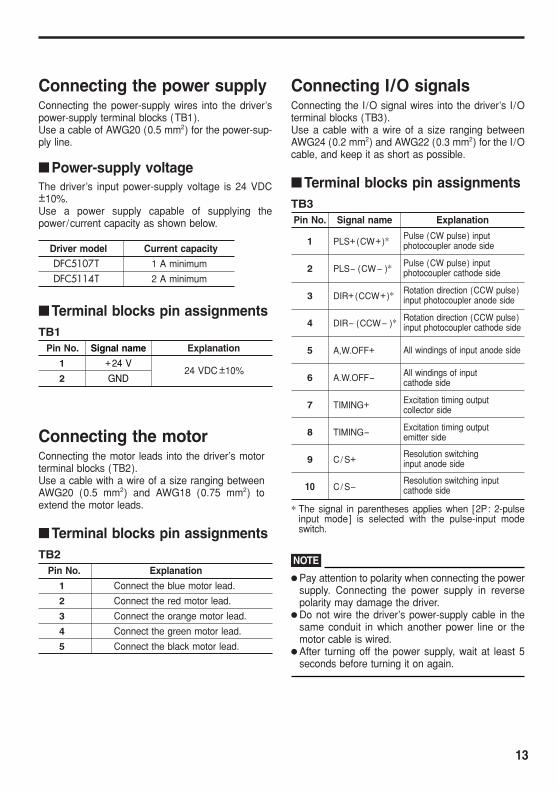
Connecting the power supply Connecting the power-supply wires into the driver’spower-supply terminal blocks (TB1).Use a cable of AWG20 (0.5 mm2) for the power-supply line.
Power-supply voltage The driver’s input power-supply voltage is 24 VDC±10%.Use a power supply capable of supplying thepower/current capacity as shown below.
Driver model Current capacity
DFC5107T 1 A minimum
DFC5114T 2 A minimum
Terminal blocks pin assignments TB1
Pin No. Signal name Explanation
1 +24 V 24 VDC ±10%
2 GND
Connecting the motor Connecting the motor leads into the driver’s motor terminal blocks (TB2). Use a cable with a wire of a size ranging between AWG20 (0.5 mm2) and AWG18 (0.75 mm2) to extend the motor leads.
Terminal blocks pin assignments TB2
Pin No. Explanation
1 Connect the blue motor lead.
2 Connect the red motor lead.
3 Connect the orange motor lead.
4 Connect the green motor lead.
5 Connect the black motor lead.
Connecting I/O signals Connecting the I/O signal wires into the driver’s I/O terminal blocks (TB3). Use a cable with a wire of a size ranging between AWG24 (0.2 mm2) and AWG22 (0.3 mm2) for the I/O cable, and keep it as short as possible.
Terminal blocks pin assignments TB3 Pin No. Signal name Explanation
1 PLS+(CW+)∗ Pulse (CW pulse) input photocoupler anode side
2 PLS (CW )∗ Pulse (CW pulse) input photocoupler cathode side
3 DIR+(CCW+)∗ Rotation direction (CCW pulse) input photocoupler anode side
4 DIR (CCW )∗ Rotation direction (CCW pulse) input photocoupler cathode side
5 A,W.OFF+ All windings of input anode side
6 A.W.OFF- All windings of input cathode side
7 TIMING+ Excitation timing output collector side
8 TIMING- Excitation timing output emitter side
9 C/ S+ Resolution switching input anode side
10 C/ S-Resolution switching input cathode side
∗ The signal in parentheses applies when [2P: 2-pulse input mode] is selected with the pulse-input mode switch.
NOTE
Pay attention to polarity when connecting the power supply. Connecting the power supply in reverse polarity may damage the driver.
Do not wire the driver’s power-supply cable in the same conduit in which another power line or the motor cable is wired.
After turning off the power supply, wait at least 5 seconds before turning it on again.
13

CW input:
Explanation of I/O signals Input signals All driver input signals are photocoupler inputs.The signal state indicates the [ON: current supplied]or [OFF: current not supplied] status of the internalphotocoupler rather than the voltage level of the signal.
Controller output Driver internal circuits
1-pulse input mode (factory setting) Connect the Pulse output of the positioning controller to the PLS+ input and PLS- input, and connect the Rotation direction output to the DIR+ input and DIR-input.
1. When the DIR input is [ON], turning the PLS input from [ON to OFF] causes the screw shaft to move forward one step.
2. When the DIR input is [OFF], turning the PLS input
R1
Open-collector output
V0
220 Ω
10~ 20 mA
+
-
PLS(CW) DIR(CCW)
Pin No.1,3
Pin No.2,4
R2
V0
470 Ω
10~ 15 mA
+
-
A.W.OFF C/S
Pin No.5,9
Pin No.6,10
from [ON to OFF] causes the screw shaft to move backward one step.
ON PLS input
OFF
DIR input ON
Forward
Backward
Forward Backward OFF
CW
Screw shaft behavior
CCW
The input signal voltage must be between 5 VDC and 24 VDC, inclusive. If the input signal voltage exceeds 5 VDC, connect external resistances (R1, R2) as illustrated above and limit the input current as follows:
V0 R1 = - 220 [Ω]
20 mA
V0 R2 = - 470 [Ω]
15 mA
PLS(CW) input and DIR(CCW) input This driver can select either 1-pulse input mode or 2pulse input mode as the pulse-input mode to match the controller used. How to set the pulse-input mode Page 20
Standard type
Guide type
CCW input:
Backward
CW input:
Forward
CCW input:
Backward
Forward
14

2-pulse input mode Connect the CW pulse output of the positioning controller to the CW+ input and CW- input, and connect the CCW pulse output to the CCW+ input and CCW-input.
1. Turning the CW input from [ON to OFF] causes the screw shaft to move forward one step.
2. Turning the CCW input from [ON to OFF] causes the screw shaft to move backward one step.
ONCW input
OFF
CCW input ON OFF
Screw shaft behavior Forward
Backward
NOTE
If a pulse signal is not input, be sure to set the photocoupler to [OFF]. Do not input pulse signals to the CW and CCW inputs simultaneously.
If one input receives a pulse signal while the other input has its photocoupler turned to [ON], the motor cannot operate correctly.
Input pulse signals should have a waveform with sharp rise/fall edges, as shown below.
H
L H:4~5 V L:0~0.6 V
90%
10%
1 s or more 1 s or more
2 s or less 2 s or less
Pulse-signal waveform
The figure shows the pulse signal’s voltage level.
A.W.OFF(All windings off) input This input is used during position adjustment by moving the screw shaft manually.
Warning
Do not turn the A.W.OFF (All windings off) input to ON while the actuator is operating. If the input is turned ON, the actuator will stop and lose its holding capability. A load may descend, resulting in injury or equipment damage.
Caution
If the screw shaft must be moved directly by hand (for manual alignment, etc.), do so after confirming that the driver’s A.W.OFF (All windings off) input is ON. Failure to do so may result in injury.
1. When the A.W.OFF input is turned to [ON], the driver cuts off the current supply to the motor and the actuator loses its holding torque. In this condition, the position of the screw shaft can be adjusted manually.
2. When the A.W.OFF input is turned to [OFF], the driver resumes the current supply to the motor and restores the actuator’s holding torque.
NOTE
When operating the motor, always keep the A.W.OFF input in the [OFF] state.
C/S (Resolution switching) input This input is used to select a desired resolution from the values set with the resolution setting switches (DATA1, DATA2). How to set the resolution setting switches
Page 18
Turning the C/S input [ON] changes the resolution to the setting of the resolution setting switch DATA2. Turning the C/S input [OFF] changes the resolution to the setting of the resolution setting switch DATA1.
Example: DRL42 Turning the C/S input [OFF] when DATA1 is set to 0
[.00016 inch (0.004 mm)] changes the resolution to .00016 inch (0.004 mm).
Turning the C/S input [ON] when DATA2 is set to 6 [.000016 inch (0.0004 mm)] changes the resolution to .000016 inch (0.0004 mm).
15

Output signals All driver output signals are photocoupler/open-collector outputs.The signal state indicates the [ON: current supplied]or [OFF: current not supplied] status of the internalphotocoupler or transistor rather than the voltage levelof the signal.
Controller input Driver internal circuits
R3 Pin No.7
Pin No.8
TIMING
V0
10 mA or less
+
-
The output signal voltage must be between 5 VDC and 24 VDC, inclusive. If the output signal voltage exceeds 5 VDC, connect external resistance as illustrated above and limit the output current 10 mA or less.
V0 R3 = [Ω]
10 mA
TIMING (Excitation timing) output This output is used to increase the accuracy of origindetection. The TIMING output turns [ON] each time the screwshaft moves by the following amount :
Movement distance ofUnit model the screw shaft [ inch (mm)]
.0008 (0.02) DRL28
.0016 (0.04) DRL42
.0032 (0.08) DRL60
Screw shaft behavior Forward Backward
TIMING output ON OFF
Movement distance of the screw shaft
Example of TIMING output not turning [ON] The chart below shows an operation in which the screw shaft is moved forward for 12 pulses at a resolution of .000016 inch (0.0004 mm) and then moved backward for one pulse at a resolution of .00016 inch (0.004 mm).
Forward 0 .00016 inch (0.004 mm)
.000016 inch .000016 inch (0.0004 mm)
.00016 inch (0.004 mm)
Stop position 12 pulses
(0.0004 mm)/step after the twelfth pulse
Backward.00016 inch
(0.004 mm)/step Stop position after the first pulse1 pulse TIMING output: None
Step [0]
NOTE
When using the TIMING output, set the number of input pulses or resolution so that the screw shaft will stop at a position corresponding to an integer-multiple of .0008 inch (0.02 mm), .0016 inch (0.04 mm) or .0032 inch (0.08 mm).
When changing the resolution using the C/S (resolution switch) input, do so when the actuator is stopped with the driver’s TIMING output turned [ON]. Switching the C/S input in any other condition may sometimes fail to turn the TIMING output [ON].
16

Timing chart
1 ms or more
CW input
C/S input
A.W.OFF input
CCW input
ON OFF
ON OFF
ON OFF
ON OFF
Power input
ON OFF
Actuator behavior
100 ms or more
100 ms or more
1 ms or more
PLS input
A.W.OFF input
DIR input
ON OFF
ON OFF
ON OFF
DATA2 DATA1
1-pulse input 2-pulse input
∗2 100 ms or more
∗1
∗2
∗3100 ms or more
0 s or more
Forward Forward
Backward
∗3
ON OFFPower input
Actuator behavior
∗1
Forward Forward
Backward
∗1. After turning off the power supply, wait at least 5 seconds before turning it on again. ∗2. When the A.W.OFF input is turned to [ON], the motor current turns off and the screw
shaft loses its holding torque. ∗3. This duration is subject to change, depending on the motor size, operating speed and
load inertial moment.
17

SettingsThis section covers the methods of setting the resolution, adjusting the motor current and switching pulse input modes.
Motor current Resolution Set the motor operating current and standstill current When setting the motor’s resolution, use the resolu- of actuator. tion setting switches (DATA1 and DATA2).
Warning
Do not set the motor operating current and standstill current too low. The actuator will lose its holding brake force and the load may drop, causing injury or equipment damage.
STOP
RUN
DATA1
DATA2
SW2
SW1
A B
C
DEF12
3 4
5 6 7 89
0 5
9
A B
C
DEF12
3 4
5 6 7 89
0 5
9
Resolution setting switches Factory settings : DATA1[0], DATA2 [0]
There are 16 settings, ranging from [0] to [F]. The resolution for each setting is given in the table below.
When changing a resolution setting, use a insulated screwdriver to switch the DATA1 or DATA2 scale.
The resolution set by DATA1 or by DATA2 is selected with the C/S (resolution switching) input. C/S (resolution switching) input Page 15
A B
C
E
4 3
0 F
D
1
2
5
67 98
DATA1, DATA2
Caution
Turn on the power to the driver after making sure all control inputs of the driver are turned OFF. Failure to do so may cause the actuator to start accidentally, resulting in injury or equipment damage.
Potentiometer for adjusting the motor standstill current (STOP)
STOP
RUN
DATA1
DATA2
SW2
SW1
A B
C
DEF12
3 4
5 6 7 89
0 5
9
A B
C
DEF12
3 4
5 6 7 89
0 5
9
Potentiometer for adjusting the motor operating current (RUN)
Resolution setting switches Number of Actuator’s resolution [ inch (mm ) ]
DATA1/DATA2 divisions DRL28 DRL42 DRL60 0 1 .00008 (0.002 ) .00016 (0.004) .00032 (0.008) 1 2 .00004 (0.001 ) .00008 (0.002) .00016 (0.004) 2 2.5 .000032 (0.0008) .000063 (0.0016) .000126 (0.0032) 3 4 .00002 (0.0005) .00004 (0.001) .00008 (0.002) 4 5 .000016 (0.0004) .000032 (0.0008) .000063 (0.0016) 5 8 .00001 (0.00025) .00002 (0.0005 ) .00004 (0.001) 6 10 .000008 (0.0002) .000016 (0.0004) .000032 (0.0008) 7 20 .000004 (0.0001) .000008 (0.0002) .000016 (0.0004) 8 25 .0000032 (0.00008) .0000063 (0.00016) .0000126 (0.00032) 9 40 .000002 (0.00005) .000004 (0.0001) .000008 (0.0002) A 50 .0000016 (0.00004) .0000032 (0.00008) .0000063 (0.00016) B 80 .000001 (0.000025) .000002 (0.00005) .000004 (0.0001) C 100 .0000008 (0.00002) .0000016 (0.00004) .0000032 (0.00008) D 125 .00000063 (0.000016) .00000126 (0.000032 ) .00000252 (0.000064) E 200 .0000004 (0.00001) .0000008 (0.00002) .0000016 (0.00004) F 250 .00000032 (0.000008) .00000063 (0.000016 ) .00000126 (0.000032)
18

[O
Motor operating current 4. After adjusting the operating current, return the cur-Factory setting: Motor’s rated current rent check switch to [OFF]. If the load is small and there is sufficient torque, the
NOTE operating current can be reduced to suppress vibration and temperature rise of the motor. After adjusting the run current, always return the cur Motor standstill current Factory setting: 50 percent of motor operating current
Setting method An ammeter is needed to set the motor current. Connect the driver, motor and DC ammeter.
Actuator DC ammeter
Motor operating current
Blue Red Orange Green Black
1 2 3 4 5
Driver TB2
rent check switch to [OFF]. If this switch is set to [ON], when the actuator stops the motor current does not decrease to the motor-standstill current level.
When adjusting the motor operating current, be sure the current doesn’t exceed the factory setting. Failure to do so may damage the actuator or driver.
Motor standstill current 1. Turn the DC check switch to [OFF].
2. Turn on the driver’s power supply.
3. Manipulate the potentiometer for adjusting the motor standstill current (STOP). Adjust the potentiometer using an insulated screwdriver. One-half the value displayed on the ammeter is
1. Turn the DC check switch to [ON].
2. Turn on the driver’s
the current per phase of the motor.
NS
C.C.
1P2P
1 2
N] DC check switch Factory setting: [OFF]
[OFF]
DRL28, DRL42 DRL60 DFC5107T DFC5114T
Ope
ratin
g cu
rren
t [A
/pha
se]
Factory setting (0.375 A/phase)
Ope
ratin
g cu
rren
t [A
/pha
se]
0.5 1.0
0.9 Factory setting (0.7 A/phase) 0.4 0.8
0.7power supply. 0.3 0.6
0.53. Manipulate the potentiometer for adjusting the motor operating current (RUN). Adjust the potentiometer using an insulated screwdriver.
0.2
0.1
0.4 0.3 0.2 0.1
0 1 2 3 4 5 6 7 8 9 10 0 1 2 3 4 5 6 7 8 9 10
One-half the value displayed on the ammeter is STOP control STOP control
the current per phase of the motor.
DRL28, DRL42 DRL60
0 STOP 10
DFC5107T DFC5114T
Ope
ratin
g cu
rren
t [A
/pha
se]
Ope
ratin
g cu
rren
t [A
/pha
se]
Factory setting (0.75 A/phase)
1.0 2.0
1.0
0 1 2 3 4 5 6 7 8 9 10
Factory setting (1.4 A/phase)
The motor current decreases to the standstill current
The scale values are0.9 1.8 not displayed on the control.0.8 1.6
1.4 1.2
0.8
level within approx. 0.1 second after pulse input stops.0.6 0.4 0.2
NOTE 0 1 2 3 4 5 6 7 8 9 10 RUN control RUN control
When adjusting the motor operating current, be sure the current doesn’t exceed the factory setting. Failure to do so may damage the actuator or driver.
The scale values are not displayed on the control.
0 RUN 10 19
0.7 0.6 0.5
0.3 0.2 0.1
0.4

Pulse-input mode Set the pulse-input mode switch to either 1-pulse input mode or 2-pulse input mode, whichever the controller uses.
NOTE
Set the pulse-input mode switch when the driver power is off.
NJ
XL1C.C.
1P2P
1 2
Pulse-input mode switch [1P] / [2P]
[1P ]
[2P ]
Factory setting: [1P:1-pulse input mode]
Setting 1-pulse input mode When operating the actuator with pulse input and rotation-direction input, switch the pulse-input mode switch to [1P].
Setting 2-pulse input mode When operating the actuator with two pulses (CW pulse input and CCW pulse input), switch the pulse-input mode switch to [2P].
20

Lead [ inch] x 0.0833 x 10⁶
Acceleration/deceleration rate [ms/kHz] x 500 [Hz] x Number of divisions
21
Operation dataThis section covers the methods of calculating thepulse-output condition and positioning time needed toset the speed and acceleration (acceleration/decel-eration rate) of the DRL series.
Conversion formulaThe pulse output must be set as in the figure below.
Set the number of pulses and pulse speed corre-sponding to the speed [ in/sec (mm/s) ] and move-ment distance [ inch (mm)] of the DRL series, basedon the following.
Pulse speed and DRL series speedThe relationship between the controller’s pulse speedand the speed of the DRL series is as follows:
Number of pulses and DRL seriesdistance of movement
The relationship between the number of controllerpulses and the distance the DRL series moves is asfollows:
DRL series speed [ in/sec (mm/s)]Pulse speed [Hz] =
Resolution [ inch (mm)]
Number of pulses [pulses] =
Acceleration /deceleration rate andacceleration
The acceleration (acceleration/deceleration rate)when the actuator is started or stopped must conformto the ranges specified in the table below, irrespectiveof the loaded mass.
The relationship between the acceleration/decelera-tion rate [ms/kHz] and the acceleration [ ft/sec2
(m/s2) ] is as follows:
Starting speedThe starting speed of the DRL series must conform tothe ranges specified in the table below.
Unit model Starting speed [ in/sec (mm/s)]
DRL28 .008 (0.2) or less
DRL42 .016 (0.4) or less
DRL60 .031 (0.8) or less
Maximum speedThe operating speed of the DRL series must conformto the ranges specified in the table below, includingduring acceleration.
Unit model Maximum speed [ in/sec (mm/s)]
DRL28 .94 (24)
DRL42 1.18 (30)
DRL60 .94 (24)
Unit model Starting speed [ in/sec (mm/s)]
DRL28 .024 (0.6) or less
DRL42 .047 (1.2) or less
DRL60 .094 (2.4) or less
If vibration occurs in a return to mechanical homeoperation, conform to the ranges specified in the tablebelow.
Operation speed
Starting speed
Pulse signal
Acceleration/deceleration rate(acceleration)
Unit model Acceleration [ ft/sec2 (m/s2) ]
DRL28 .66 (0.2) or less
DRL42 1.31 (0.4) or less
DRL60 .85 (0.26) or less
Unit model Acceleration/deceleration rate
DRL28 10/number of divisions ms/kHz or more
DRL42 10/number of divisions ms/kHz or more
DRL60 30/number of divisions ms/kHz or more
DRL series distance of movement [ inch (mm)]
Resolution [ inch (mm)]
Acceleration [ ft/sec2] =
Lead [mm] x 103
Acceleration/deceleration rate [ms/kHz] x 500 [Hz] x Number of divisions
Acceleration [m/s2] =

Positioning time The following explains the formula for calculating the positioning time (reference value) of the DRL series: Since there is settling time dependent on such factors as the load’s inertial moment and the speed setting, use these values only as a reference.
Vr : Operating speed [ in/sec (mm/s)] Vs : Starting speed [ in/sec (mm/s)] L : Movement distance [ inch (mm)] a : Acceleration [ ft/sec2 (m/s2) ] T : Positioning time [s]
1. Check the operating pattern Calculate the maximum speed Vrmax during operation ( triangular drive) from the acceleration a , travel L and assumed operating speed Vr .
Vrmax = √ L [ inch] x a [ ft/sec2] x 12 + Vs2 [ in/sec] [ in/sec] Vrmax = √ L [mm] x a [m/s2] x 103 + Vs2 [mm/s][mm/s]
Vrmax : Maximum speed when a triangular-drive running pattern is assumed
When the maximum speed is at or below the running speed: Triangular drive
Speed
Vr
Vrmax
a
Vs
T Time
When the maximum speed exceeds the running speed: Trapezoidal drive
Speed
Vrmax
Vr a
Vs
T Time
However, for trapezoidal drive the maximum speed is not used. Instead, the hypothesized running speed Vr is used.
2. Calculate the positioning time according to the running pattern
Calculate the positioning time according to the running pattern.
Triangular drive
2 x (Vrmax [ in/sec] – Vs [ in/sec])T [s] =
a [ ft/sec2] x 12
2 x (Vrmax [mm/s] – Vs [mm/s])T [s] =
a [m/s2] x 103
Trapezoidal drive
(Vr [ in/sec] – Vs [ in/sec])2 + L[ inch] x a [ ft/sec2] x 12 T [s] =
Vr [ in/sec] x a [ ft/sec2] x 12
(Vr [mm/s] – Vs [mm/s])2 + L[mm] x a [m/s2] x 103
T [s] = Vr [mm/s] x a [m/s2] x 103
Example Calculate the positioning time
1. Calculate the positioning time for running the DRL42 using the following settings.
Movement distance L : 1.574 inch (40 mm) Starting speed Vs : .016 in/sec (0.4 mm/s) Acceleration a : 1.31 ft/sec2 (0.4 m/s2) Operating speed Vr : 1.181 in/sec (30 mm/s)
2. Check the operating pattern
Vrmax = √ 1.574 x 1.31 x 12 + 0.0162 = 4.974 [ in/sec]
Vrmax = √ 40 x 0.4 x 103 + 0.42 = 126.49 [mm/s]
Since the maximum speed exceeds the operating speed, trapezoidal drive used.
3. Calculate the positioning time From the formula for trapezoidal drive
Unit = inch
(1.181 – 0.016)2 + 1.574 x 1.31 x 12T =
1.181 x 1.31 x 12
= 1.4 [s]
Unit = mm
(30 – 0.4)2 + 40 x 0.4 x 103
T = 30 x 0.4 x 103
= 1.4 [s]
22

Settling time With the DRL series, the load inertial moment and other factors cause a response delay with respect to the pulse input. A delay thus caused at stopping is called the [settling time]. The calculation of accurate positioning time requires that this settling time be considered.
Speed [in/sec (mm/s)]
Acceleration time
Motor running waveform Pulse signal
Time [s]
Settling timePositioning time
Actual positioning time
Operational use of the actuator thrust
The maximum thrust of the actuator is measured during constant-speed operation without loaded mass. To [push] or [pull ] an external force with the actuator table, a thrust against the external force is required in addition to a thrust for carrying the jig that receives the external force. Check the necessary thrusts when [pushing] or [pulling] an external force with the table.
Thrust required to accelerate the table’s load mass:
a [ ft/sec2]Fa [ lb.] = m [ lb.] x (
g [ ft/sec2] + µ )
Fa [ lb.] = m [kg] x (a [m/s2] + g [m/s2] + µ)
Maximum push/pull thrust:
Fa = Fmax – Fa
When the thrust applied to the jig is less than F , pushing and pulling using the actuator is possible.
Load ( jig + load)
External force
Fmax : Maximum thrust of actuator [ lb. (N)]
Fa : Thrust required to carry load ( jig + load) [ lb. (N)]
F : Thrust with which the load mass can be pushed and
pulled by an external force [ lb. (N)]
m : Mass of load ( jig + load) [ lb. (kg)]
a : Acceleration [ ft/sec2 (m/s2) ]
g : Acceleration due to gravity 32.2 (9.807) [ ft/sec2 (m/s2)]
µ : Friction coefficient of linear guide 0.01
NOTE
Operating the actuator under a load beyond the maximum thrust or allowing the table to remain locked may cause damage to the actuator. Therefore, always operate the actuator under a load not exceeding the maximum thrust. In a lift application, operate the actuator under a load not exceeding the maximum vertical load and without the application of external force.
m
linear guide
23

InspectionIt is recommended that the following items be checked regularly after operation.Should an abnormality be noted, discontinue any use and contact your nearest Oriental Motor office.
Inspection items Are there any foreign objects on the driver ? Are there any loose driver-mounting screws ? NOTE Are any of the power elements or smoothing capac- The driver uses semiconductor elements, so exer
itors inside the driver giving off a bad smell or show- cise due caution when handling the driver. The driing other signs of abnormality ? ver may be damaged by the effects of static elec
tricity, etc.
24

Troubleshooting and remedial actions During DRL series operation, the actuator or driver may fail to operate properly due to an error in speed setting or inappropriate connection. If the DRL series doesn’t operate properly, refer to this section and take appropriate action. If the problem persists, contact your nearest Oriental Motor office.
Phenomenon Possible cause Remedial action
The actuator is not energized. The screw shaft can be moved by hand.
An anti-spin mechanism is not provided for the screw shaft.
With the standard-type actuator, the screw shaft can be moved by hand even during excitation. Always equip the product with an external anti-spin mechanism.
The A.W.OFF input is turned [ON].
Turn the A.W.OFF input to [OFF] and determine whether the actuator is energized.
Inappropriately adjusted motor operating current.
Return the potentiometer for adjusting the motor operating current (RUN, STOP) to the factory-set value and check the operation
The screw shaft doesn’t rotate.
Poor contact at the CW input or CCW input.
Check the controller and driver connections Check the pulse-signal specifications (voltage, width)
Both the CW and CCW inputs are turned to [ON] in 2-pulse input mode.
Input pulse signal to either the CW input or CCW input once at a time.
Be sure to turn [OFF] the terminal not receiving input.
The pulse signal is connected to the DIR input in 1-pulse input mode.
Connect pulse signal to the PLS input.
The screw shaft rotates opposite to the specified direction.
The CW input and CCW input are connected in reverse, when the 2-pulse input mode is selected.
Connect the CW pulse signal and CCW pulse signal to the CW input and CCW input, respectively.
The DIR. input is set in reverse, when the 1-pulse input mode is selected.
Turn the switch [ON] when the direction is set to CW; turn it [OFF] when the direction is set to CCW.
The screw shaft operation is unstable.
Inappropriately adjusted motor operating current.
Return the potentiometer for adjusting the motor operating current (RUN, STOP) to the factory-set value and check the operation
Poor connection of the pulse signal.
Check the controller and driver connections. Check the pulse-signal specifications (voltage, width ).
25

Phenomenon Possible cause Remedial action
A misstep occurs during acceleration or operation.
Large load or significant load fluctuation.
Check to see if the load fluctuates significantly during actuator operation.
The starting speed is too high. Set a lower starting speed at which the motor can be started reliably.
The acceleration (deceleration) time is too short.
Set a longer acceleration (deceleration) time at which the motor can be started reliably.
Effect of noise. If effect of noise is confirmed, take an appropriate action such as isolating the motor from the noise source, redoing the wiring or changing the I/O cables to shielded wires
The actuator’s travel amount doesn’t match the setting.
Inappropriate switching of C/S (resolution switch) input.
Check the settings of the resolution setting switches (DATA1, DATA2) and the switching condition of the C/S input.
The motor vibrates significantly.
Small load. Turn the potentiometer for adjusting the motor operating current (RUN)slightly in the counterclockwise direction in order to lower the current.
Vibration will increase if the motor’s output torque is too large for the load.
The actuator is abnormally hot.
The DC check switch is set to the [ON] side.
Set the DC check switch to the [OFF] side.
The setting of the potentiometer for adjusting the motor standstill current (STOP) is too high.
Return the potentiometer for adjusting the motor standstill current (STOP) to the factory-set value and check the operation.
Automatic current-cutback doesn’t occur.
The DC check switch is set to the [ON] side.
Set the DC check switch to the [OFF] side.
The setting of the potentiometer for adjusting the motor standstill current (STOP) is too high.
Return the potentiometer for adjusting the motor standstill current (STOP) to the factory-set value and check the operation.
The pulse signal hasn’t returned to [OFF].
Once the operation is stopped, set the pulse signal to [OFF].
TIMING signal is not output.
The C/S input was turned [ON] while TIMING signal was not output.
Turn the C/S input [ON] when the TIMING signal is output.
An abnormal noise is heard.
Poor installation accuracy of actuator.
Check the installation accuracy of the actuator.
26
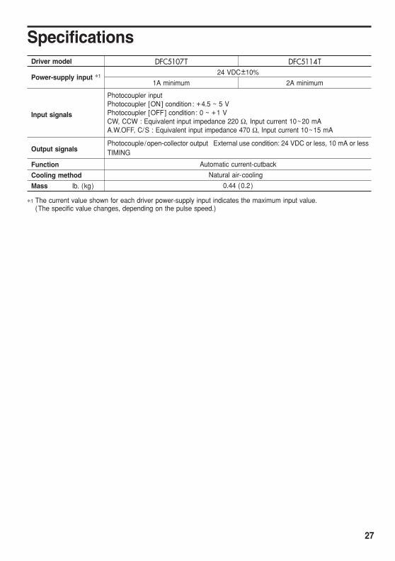
SpecificationsDriver model DFC5107T DFC5114T
Power-supply input ∗1 24 VDC±10%
1A minimum 2A minimum
Input signals
Photocoupler input Photocoupler [ON] condition: +4.5 ~ 5 V Photocoupler [OFF] condition: 0 ~ +1 V CW, CCW : Equivalent input impedance 220 Ω, Input current 10~20 mA A.W.OFF, C/S : Equivalent input impedance 470 Ω, Input current 10~15 mA
Output signals Photocouple/open-collector output External use condition: 24 VDC or less, 10 mA or less TIMING
Function Automatic current-cutback
Cooling method Natural air-cooling
Mass lb. (kg) 0.44 (0.2)
∗1 The current value shown for each driver power-supply input indicates the maximum input value. (The specific value changes, depending on the pulse speed.)
27