ORGANIZATIONAL MAINTENANCE MANUAL TRUCK, LIFT,...
75
TM 10-3930-618-20 TECHNICAL MANUAL ORGANIZATIONAL MAINTENANCE MANUAL TRUCK, LIFT, FORK; GASOLINE ENGINE DRIVEN; PNEUMATIC TIRED WHEELS; 6000 LB. CAPACITY; 168 INCH LIFT; ALLIS-CHALMERS MODEL FP60-24PS; ARMY MODEL MHE-213, FSN 3930-935-7979 HEADQUARTERS, DEPARTMENT OF THE ARMY February 1971
Transcript of ORGANIZATIONAL MAINTENANCE MANUAL TRUCK, LIFT,...

TM 10-3930-618-20
TECHNICAL MANUAL
ORGANIZATIONAL MAINTENANCE MANUALTRUCK, LIFT, FORK; GASOLINE ENGINE DRIVEN;PNEUMATIC TIRED WHEELS; 6000 LB. CAPACITY;
168 INCH LIFT; ALLIS-CHALMERSMODEL FP60-24PS;
ARMY MODEL MHE-213, FSN 3930-935-7979
HEADQUARTERS, DEPARTMENT OF THE ARMYFebruary 1971

T M 1 0 - 3 9 3 0 - 6 1 8 - 2 0
TECHNICAL MANUAL
No. 10-3930-618-20
HEADQUARTERSDEPARTMENT OF THE ARMY
WASHINGTON, D.C. February 1971
Paragraph
CHAPTER 1.Section I.
II.CHAPTER 2.
Section I.II.
III.IV.
V.VI.
VII.VIII.
IX.X.
XI.XII.
XIII.XIV.XV.
XVI.XVII.
APPENDIX A.B.
INDEX
ORGANIZATIONAL MAINTENANCE MANUAL
TRUCK, LIFT, FORK; GASOLINE ENGINE DRIVEN;PNEUMATIC TIRED WHEELS; 6000 LB. CAPACITY;
168 INCH LIFT; ALLIS-CHALMERS MODEL FP60-24PS;ARMY MODEL MHE-213, FSN 3930-935-7979
INTRODUCTIONGeneralDescription and dataORGANIZATIONAL MAINTENANCE INSTRUCTIONSService upon receipt of materialRepair parts, special tools and equipmentPreventive maintenance checks and servicesTroubleshootingMaintenance of the engineMaintenance of the fuel systemMaintenance of the exhaust systemMaintenance of the cooling systemMaintenance of the electrical systemMaintenance of the transmissionMaintenance of the front drive axleMaintenance of the rear steering axleMaintenance of the brakesMaintenance of the wheelsMaintenance of the steering systemMaintenance of the body and overhead guardMaintenance of the hydraulic lift componentsREFERENCESMAINTENANCE ALLOCATION CHART
1-11-3
2-12-22-5
2-72-152-222-242-302-432-462-492-512-552-592-622-64
Page
1-11-4
2-12-12-12-32-82-162-222-232-312-412-412-412-422-442-462-502-50A-1B-1I-1
i
Richard Woods
24 February 1971

LIST OF ILLUSTRATIONSPage
1-21-31 - 51 - 6
2-92-102-112 - 1 22-132-132-142-152-162-172 - 1 82-192-202-212-222-232-242-252-262-262-272-282-292-302-322-332-342-352-362-372-38
2-392-392-402-422-422-432-432-452-462-482-492-492-502-512-512-522-522-522-53
Number
1-11-21-31-42-12-22-32-42-52-62-72-82-9
2-102-112-122-132-142-152-162-172-182-192-202-21
2-222-232-242-252-262-272-282-292-302-312-322-332-342-352-362-372-382-392-402-412-422-432-442-452-462-472-482-492-50
Title
Truck, fork lift, left rear, three quarter view.Truck, fork lift, right front, three quarter view.
Wiring diagram.Hydraulic diagram.Engine, right side view.
Engine, left side view.Engine, rear view (fan end).Adjusting valve clearance.Engine oil filter, installed view.Manifold assembly, installed view.Flywheel timing mark.Distributor timing adjustment.Timing light connections.
Carburetor air cleaner, installed view.Carburetor, installed view.Fuel pump and hydraulic filter, installed view.Governor adjustments.Accelerator pedal and linkage, exploded view.Fuel tank, exploded view.
Muffler and pipes, installed view.Counterweight, installed view.Radiator, installed view.Drain valve, radiator.Drain valve, block.Alternator, installed view.Water pump, installed view.Thermostat and water temperature sending unit, installed view.
Testing thermostat (typical).Voltage regulator, installed view.Starter motor, installed view.Ignition distributor, installed view.Ignition distributor, exploded view.Battery and cables, installed view.Headlight, exploded view.Combination rear light, exploded view.Horn and horn relay, installed view.Transmission neutral switch, installed view.Hour meter switch, installed view.Handbrake lever, installed view.Handbrake lower cable yoke adjustment.Brake pedal adjustment.Brake master cylinder and brake power booster, installed view.Drive wheel, rim, tire and tube, exploded view.Steer wheel, rim tire and tube, exploded view.Power steering cylinder, installed view.Tie rod, exploded view.C h e c k i n g b e t w e e n s p i n d l e a n d s t o p .
Overhead guard, exploded view.Checking mast tilt.Tilt cylinder adjustment.Lift chain, installed view.Lift chain adjustment.Removing hydraulic oil tank breather.Micron type hydraulic fluid filter, installed view.
ii

CHAPTER 1INTRODUCTION
Section I. GENERAL
1 - 1 S c o p ea. These instructions are published for the use of
the personnel responsible for organizational mainte-
maintenance services, repairs, troubleshooting, andorganizational maintenance procedures.
b. Repair parts and special tools for organizationalmaintenance will be found in TM 10-3930-618-20P.
nance of the fork lift truck shown in figures 1-1 and1-2. They provide additional information, description
c. Instructions for destruction of equipment to
and data not covered in the operator’s manual andprevent enemy use will be found in TM 750-244-3.
instructions for preparing the equipment for preventived. Instructions for administrative storage of equip-
ment will be found in TM 740-90-1.
l - l

Figure 1-1. Truck, fork lift, left rear, three quarter view.
1-2

Figure 1-2 Truck, fork lift, right front, three quarter view.
1-3

1-2. Forms and Recordsa. DA Forms and records used for equipment main-
tenance will be only those prescribed in TM 38-750.b. The reporting of errors, omissions, and recom-
mendations for improving this publication by theindividual user is encouraged. Reports should be sub-
mitted on DA Form 2028 (Recommended Changes toPublications) and forwarded direct to (CommandingGeneral, U.S. Army Mobility Equipment Command,ATTN: AMSME-MPP, 4300 Goodfellow BoulevardSt. Louis, Mo. 63120.
Section II . DESCRIPTION AND DATA
1-3. DescriptionArmy Model MHE-213 (Allis-Chalmers Model FP60-24PS) trucks are non-tactical forklift trucks designedfor use in a warehouse or on hard surface pavement.The truck (fig. 1-1 and 1-2) can be used to load,transport and unload, and stack loads weighing asmuch as 6000 lbs. at a load center of 24 inches and ranlilt the load to a height of 168 inches. (The load centeris measured from the heel of the forks.) The truck ispowered by a six cylinder, liquid-cooled, gasolineengine and is equipped with power assist brakes, powersteering, and single speed automatic transmission.
NOTET h r o u g h o u t t h i s m a n u a l , t h e u s e o f t h e t e r m s r i g h t , l e f t ,
f r o n t , a n d r e a r i n d i c a t e s d i r e c t i o n s f r o m t h e v i e w p o i n t o f
t h e o p e r a t o r s i t t i n g i n t h e s e a t o f t h e t r u c k .
( 2 ) C a p a c i t i e s .
C o o l i n g s y s t e m 1 6 Q t
D r i v e a x l e d i f f e r e n t i a l 3 Q t
P l a n e t a r y g e a r h o u s i n g ¾ Q t
E n g i n e c r a n k c a s e ( w i t h f i l t e r ) 7 Q t
F u e l t a n k 1 4 . 5 G a l
H y d r a u l i c s y s t e m :
B r a k e m a s t e r c y l i n d e r ¼ P t
L i n e s 1 P t
T a n k ( l i f t h y d r a u l i c s y s t e m ) 2 8 Q t
T r a n s m i s s i o n ( w i t h f i l t e r ) 1 1 Q t
( 3 ) H y d r a u l i c s y s t e m ( s t e e r i n g )
F l o w r e g u l a t o r s e t t i n g 2 . 5 t o 3 . 2 g . p . m . @ 1 2 0 0 p s i
( 4 ) H y d r a u l i c s y s t e m ( m a i n )
P r o p e r s e t t i n g 2 0 0 0 p s i @ 1 8 0 0 R P M
(5) Cr i t i c a l t o rque va lve s .
C y l i n d e r h e a d b o l t s 1 1 0 f t - l b
S p a r k p l u g s 1 5 - 2 0 f t - l b
( 6 ) B a t t e r y .
V o l t a g e
T e r m i n a l g r o u n d e d
(7 ) Va lves .
I n t a k e v a l v e c l e a r a n c e ( c o l d ) 0 .012 in .
I n t a k e c l e a r a n c e ( h o t ) ( e n g i n e
c o o l a n t a t n o r m a l o p e r a t i n g
t e m p e r a t u r e ) 0 .010 in .
E x h a u s t v a l v e c l e a r a n c e ( c o l d ) 0 .014 in .
E x h a u s t v a l v e c l e a r a n c e ( h o t ) ( e n g i n e
a t n o r m a l o p e r a t i n g t e m p e r a t u r e ) 0 .012 in .
( 8 ) S p a r k p l u g s
S i z e 1 4 m m
P o i n t g a p 0 . 0 2 5 i n .
( 9 ) D i s t r i b u t o r
P o i n t g a p 0 . 0 2 2 i n .
1-4. Identification and Tabulated Dataa. Identification. The truck has one identification
plate. It is located in the center of the instrument panel.It contains information pertaining to the manu-facturer, model. nomenclature, contract number, seri-al number, registration number, Federal Stock Sum-ber, engine serial number, capacity, and date shipped.
b. Tabulated Data.M a n u f a c t u r e r Al l i s -Cha lmers
M o d e l F P 6 0 - 2 4 P S
A r m y M o d e l M H E - 2 1 3
(1) Engine
M a k e A l l i s - C h a l m e r s
M o d e l 6 m b - 2 3 0
G o v e r n e d s p e e d 2 2 0 0 R P M
F i r i n g o r d e r 1 - 5 - 3 - 6 - 2 - 4
I d l e s p e e d 5 0 0 R P M
1-4

(10) Wiring diagram. See figure 1-3
Figure 1-3. Wiring diagram.
1-5
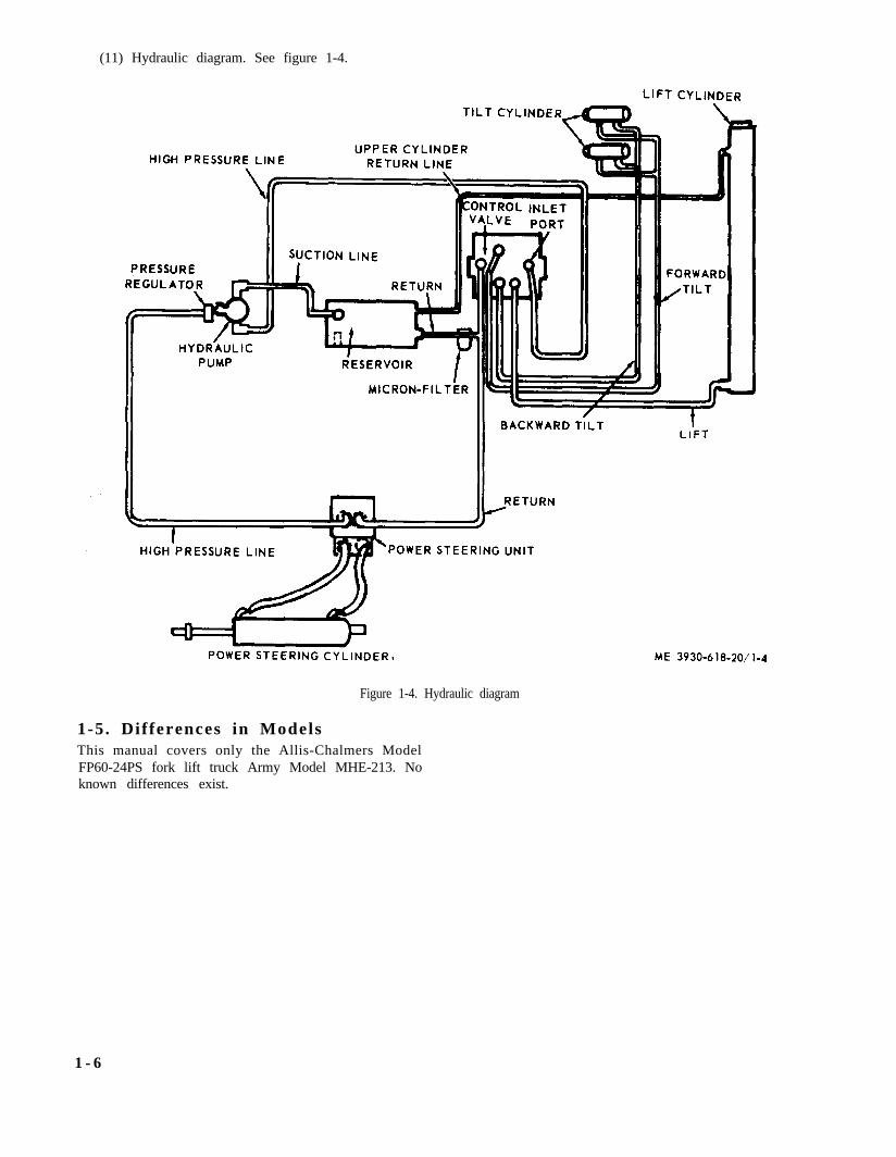
(11) Hydraulic diagram. See figure 1-4.
Figure 1-4. Hydraulic diagram
1-5. Differences in ModelsThis manual covers only the Allis-Chalmers ModelFP60-24PS fork lift truck Army Model MHE-213. Noknown differences exist.
1 - 6

CHAPTER 2ORGANIZATIONAL MAINTENANCE INSTRUCTIONS
Section I. SERVICE UPON RECEIPT OF MATERIAL
2 - 1 . I n s p e c t i n g a n d S e r v i c i n g t h eEquipmentInspect the truck for any signs of damage. Check
radiator for proper coolant level and engine for properengine oil level. Inflate tires to proper pressure. Checkbattery for proper electrolyte level and transmissionfor proper oil level. Fill fuel tank.
Section II. REPAIR PARTS, SPECIAL TOOLS AND EQUIPMENT
2-2. Tools and Equipment
No tools or equipment are authorized for organiza-tional maintenance.
2-3. Special Tools and Equipment
2-4. Repair PartsRepair parts and equipment are listed and illustratedin TM 10-3930-618-20P.
No special tools or equipment are authorized for organi-zational maintenance.
Section I l l . PREVENTIVE MAINTENANCE CHECKS AND SERVICES
2-5. GeneralTo insure that the truck is ready for operation at alltimes, it must be inspected systematically so thatdefects may be discovered and corrected before theyresult in serious damage or failure. Defects discoveredduring operation of the truck will be noted for futurecorrection, to be made as soon as operation has ceased.Stop operation immediately if a deficiency is notedduring operation which would damage the equipmentif operation were continued.
2-6. Quarterly Preventive MaintenanceServ i ce sThe sequence numbers indicate the sequence of mini-mum inspection requirements. The letter after thesequence number indicates the special frequencyrequired for this check. If no letter is shown in columnone of the table, the check is to be made on a quarterlybasis. See legend at bottom of table 2-1.
T a b l e 2 - 1 . P r e v e n t i v e M a i n t e n a n c e C h e c k s a n d S e r v i c e s
1
2
3
X
X
X
B r a k e M a s t e r C y l i n d e r ( p a r a 2 - 5 3 )
B a t t e r y a n d C a b l e s
Dis t r ibu to r
C h e c k f o r i m p r o p e r f l u i d l e v e l . R e f e r t o
c u r r e n t L O a n d r e f i l l t o w i t h i n 3 / 8 i n . t o
1 / 2 i n . f r o m t o p o f r e s e r v o i r . I n s p e c t f o r
l e a k s a n d i n s e c u r e m o u n t i n g . C h e c k t i l l e r
c a p v e n t f o r c l o g g e d c o n d i t i o n .
I n s p e c t b a t t e r y f o r c r a c k s a n d b r e a k s . I n -
s p e c t c a b l e s a n d t e r m i n a l s f o r c o r r o s i o n
a n d b r e a k s . I n s p e c t b a t t e r y f r a m e f o r
s e c u r i t y , b r e a k s a n d c o r r o s i o n .
I n s p e c t f o r c r a c k s , c a r b o n s t r e a k s , c o r r o d e d
t e r m i n a l s . a n d i n s e c u r e m o u n t i n g . I n -
s p e c t c o n t a c t p o i n t s f o r b u r n s , p i t s ,
f r o s t i n g , m i s a l i g n m e n t , a n d i m p r o p e r
s e t t i n g . A d j u s t g a p .
( p a r a 2 - 3 7 )
( p a r a 2 - 3 4 )
2-1

Table 2-1. Preventive Maintenance Checks and Services (Cont'd)
4 X
X
X
X
X
X
X
X
X
X
X
X
(para 2-9)
TM 10-3930-618-10
5
6
7
8
9
10
11
12
13
*14M
15
1617
Spark Plugs
Steering Axle
Radiator
Breather Lines
Fire Extinguisher
V-Belt and Pulleys
Hydraulic Fluid Tank
Inching and Service BrakePedals and Linkage
Hand Brake Lever andLinkage
Tilt Cylinders
Lights
Lift Chains
Lift CylinderControls and Instruments
Remove, clean and test spark plugs. Adjustgap to 0.025 in. Torque spark plugs 15 to20 ft-lbs.
Inspect steering axle for insecure mounting.Inspect king pins and center arm forinsecure mounting and wear. Checkwheels to be sure there is 0° toe-in.
Inspect for insecure mounting, leaks, bentfins, and obstructions. If necessary addcoolant until level is just below filler neck.
Crankcase vent hose and vent line fromrocker arm cover may be cleaned withcompressed air. Rocker arm cover valvemay be cleaned with a cleaning solvent.
Inspect for broken seal. Replace extin-guisher if gage does not indicate fullcharge.
Inspect belt for frayed condition, wear,glazing, and deterioration. Inspectpulleys for breaks and insecure mountingAdjust V-belt for ½ inch deflection midway between pulleys.
Check level of hydraulic fluid. Refer tocurrent LO and add fluid as requiredClean or replace the breather filters andline filters.
Check service brake pedal for free travelof ½ inch. Inspect for insecure linkage.Inspect inching pedal and linkage forimproper adjustment.
Inspect for insecure mounting, improperoperation. and maladjustment. Checkcable for wear and frayed condition.
Check for leaks and insecure mounting.Adjust for correct degree of tilt of 3° for-ward and 10° back.
Inspect for burned out lamps and defectiveleads. Replace lamps and leads as neces-sary.
Inspect chains for wear and inspect rollersfor breakage and binding. Adjust chainso that the carriage lifts evenly.
Inspect for leaks and insecure mounting.Replace damaged instruments. Tighten
loose mountings. With engine running,cheek controls and instruments for im-proper operation. The normal instrumentreadings are:
Ammeter-Indicates slight positive chargeHourmeter-Register total hours of opera-
tionOil pressure gage-25 to 30 psiTemperature gage-160°F. to 180°F.
(para 2-35)
(para 2-50)
(para 2-25)
(para 2-26)
(para 2-68)
(para 2-52)
(para 2-51)
(para 2-66)
(para 2-39)
(para 2-67)
2-2

Section IV. TROUBLESHOOTING
This section contains information useful in diagnosingand correcting unsatisfactory operation or failure ofthe truck. Malfunctions which may occur are listed intable 2-2. Each malfunction is followed by a list of
probable causes of the trouble. The corrective actionrecommended is described opposite the probablecause.
Malfunction
1. Engine will not start (no spark. Am-meter shows no discharge. Zero read-ing with ignition switch on).
2. Engine will not start (ammeter showsabnormal discharge with ignitionswitch on).
3. Engine will not start (weak spark orno spark).
4. Engine will not start (good spark).
5. Engine backfires.
6. Engine operates erratically.
Table 2-2. Troubleshooting
Probable cause
a. Ignition switch defective.b. Ignition primary wires or starting motor
cables broken or connections loose.c. Ignition coil primary winding open.d. Distributor points dirty.e. Distributor points not closing.f. Loose or corroded ground or battery cable
connection.a. Short-circuited or burned distributor cap or
rotor.b. Short-circuited wire between ammeter and
Ignition switch.c. Short-circuited primary winding in ignition
coil.a. Distributor points not opening.
b. Distributor points pitted or burred.c. Distributor capacitor weak.d. Ignition coil weak.e. Primary wire connections loose.f. High-tension wires, spark plug wires, or dis-
tributor cap wet.g. High-tension wires, spark plug wires, or dis-
tributor cap damagedh. Distributor cap or rotor burred or broken.i. Spark plug gaps incorrect.j. Short-circuited secondary circuit in ignition
coil.a. Fuel tank empty.b. Dirt or water in carburetor or float switch.c. Carburetor and engine flooded by excessive
use of choke.d. Fuel not reaching carburetor.
e. Dirt in fuel lines or tanks.
f. Fuel line pinched.g. Ignition wires incorrectly installed in dis-
tributor cap.h. Ignition timing incorrect.i. Fuel pump not pumping.j. Lack of engine compression.a. Ignition out of time.b. Spark plug wires incorrectly installed in dis-
tributor cap or at spark plugs.c. Distributor cap cracked or shorted.d. Valve holding open.a. Improper ignition timing.b. Spark plug wires incorrectly installed in dis-
tributor cap.c. Dirt or water in carburetor.d. Carburetor improperly adjusted.e. Valve sticking, not seating properly, burned
or pitted.
2-34).a. Clean or replace and adjust points (para
b. Clean or replace (para 2-34).c. Replace capacitor (para 2-34).d. Replace coil (para 2-36).e. Tighten connections.f. Dry thoroughly.
Corrective action
a. Replace switch.b. Repair or replace and tighten.
c. Replace coil (para 2-36).d. Clean and adjust points (para 2-34).e. Adjust or replace points (para 2-34).f. Remove, clean, reinstall, tighten cable
lamps (para 2-37).a. Replace defective parts (para 2-34).
b. Repair or replace wire.
c. Replace coil (para 2-36).
g. Replace defective parts.
h. Replace defective parts (para 2-34).i. Reset gaps (para 2-35).j. Replace coil (pars 2-36).
a. Refill tank.b. Replace carburetor (para 2-17).c. Depress accelerator pedal fully and crank
engine:d. Inspect for damaged or leaky lines or air
leak into line between tank and fuel pump.e. Disconnect lines, drain tank and blow out
lines (para 2-21).f. Repair or replace line.g. Install wires correctly.
h. Reset timing (para 2-14).i. Replace fuel pump (para 2-18).j. Report to direct support maintenance.a. Reset timing (para 2-14).b. Install wires correctly.
c. Replace cap (para 2-34).d. Report to direct support maintenance.a. Reset timing.b. Install wires correctly.
c. Drain carburetor, clean fuel system.d. Adjust carburetor (para 2-17).e. Report to direct support maintenance.
2-3

Table 2-2. Troubleshooting (Cont’d)
Malfunction
7. Engine stalls on idle.
8. Engine misfires on one or more cylinders.
9. Engine does not idle properly
10. Engine misses at high speed.
11. Engine pings.
12. Engine lacks power
2-4
Probable cause
f. Excessive carbon cm cylinder head.g. Valve springs weak.h. Fuel pump, pressure low.i. Fuel filter clogged.j. Partly clogged or pinched furl lines.k. Intake manifold leak,l. Distributor cap cracked or shorted.a. Carburetor throttle valve closes.b. Carburetor choke remaining closed.c. Dirt or water in idler passages of carburetor.d. Air leaks at intake manifold.
e. Spark plugs defective, yaps incorrect.
f. Ignition timing early.g. Low compression.a. Dirty spark plugs.
e. Clean or replace spark plugs, set gapclearance (para 2-35).
f. Reset timing (para 2-14).g. Report to direct support maintenance.a. Clean, adjust or replace plugs (para 2-35).b. Replace spark plugs (para 2-35)c. Replace wires.d. Install wires correctly.
b. Cracked spark plug porcelain.c. Spark plug wires grounded.d. Spark plug wires incorrectly installed in cap
or at spark plugs.e. Distributor cap on rotor burned or broken.f. Valve tappet holding valve open.g. Low engine compression.h. Cracked cylinder block or broken valve
tappt or tappet screw.a. Spark plugs dirty or gap too close.b. Ignition timing incorrect.a. Distributor points sticking, dirty, or im-
properly adjusted.b. Distributor rotor or cap cracked or burred. b. Replace defective parts (para 2-34)
e. Replace defective parts (para 2-34).f. Report to direct support maintenance.g. Report to direct support maintenance.h. Report to direct support maintenance.
a. Clean and adjust spark plugs (para 2-35).b. Reset timing (para 2-14).a. Clean, adjust, or replace points (para
2-34).
c. Uneven cylinder compression.d. Leaking high tension or spark plug wires,
cracked insulation.e. Carburetor choke not adjusted.f. Defective carburetor accelerating pump sys-
tem, dirt in metering jets, or incorrect float levelg. Fuel pump defective, causing lack of fuel.
h. Air cleaner dirty.
i Valves sticking: weak or broken valvesprings.
j. Fuel filter clogged.k. Weak distributor breaker arm spring.l. Excessive play in distributor shaft bearing.a. Ignition timing early.b. Distributor automatic spark advance stuck
in advance position. or spring broken.c. Incorrect fuel.a. Ignition timing late.b. Incorrect fuel.c. Engine running cold
d. Insufficient oil or improper grade of oil.
e. Oil system failure.f. Air cleaner dirty.
g. Spark plug gaps too wide.h. Choke partially closed, or throttle not open-
ing fully.
Corrective action
f. Report to direct support maintenance.g. Report to direct support maintenance.h. Replace pump (para 2-18).i. Replace filter (para 2-18).j. Clean and repair lines.k. Inspect gaskets and tighten.l. Replace cap (para 2-34).a. Adjust carburetor (para 2-17).b. Adjust choke cable (para 2-17).c. Drain carburetor (para 2-17).d. Tighten manifold stud nuts or replace
gaskerts (para 2-11).
c. Report to direct support maintenance.d. Replace defective parts.
e. Adjust choke (para 2-17)f. Replace carburetor (para 2-17)
g. Replace fuel pump (para 2-18)
h. Clean air cleaner and refill oil cup (para2-16).
i. Report to direct support maintenance.
j. Remove and clean strainer (para 2-18).k. Replace point set (para 2-34).l. Replace distributor (para 2-34).a. Reset timing (para 2-14).b. Replace distributor (para 2-34).
c. Drain, use correct fuel.a. Reset timing (para 2-14).b. Use correct fuel.c. Test thermostat (para 2-28). In cold
weather cover air intake under driver’s seat.d. Lubricate in accordance with lubrication
order.e. Report to direct support maintenance.f. Clean air cleaner, change oil in cup (para
2-16).g. Reset gaps (para 2-35).h. Adjust choke (para 2-17), accelerator
pedal (para 2-20), and governor linkage (para2-19).

Table 2-2. Troubleshooting (Cont’d)
Malfunction Probable cause Corrective action
13. High oil consumption.
14. Low engine oil pressure.
15. Poor engine compression.
16. Fuel does not reach carburetor.
17. Fuel reaches carburetor, but doesreach cylinders.
18. High fuel consumption.
not
i. Exhaust pipe. muffler or tailpipe obstructed.
j. Low compression, broken valve springs,sticking valves
k. Improper tappet adjustment.l. Lack of fuel.
a. High engine speeds.b. Oil leak.c. Improper grade of oil or diluted oil.d. overheating of engine causing thinning of oil.e. Defective piston or rings; excessive side
clearance of intake valves in guides; cylinder boresworn (scored, out-of-round, tapered); worn ordamaged seals.
a. Insufficient oil supply.b. Improper grade of oil or diluted
c. Oil too heavy.
d. Oil leaks.e. Oil pump faulty; pressure regulator valve
stuck or improperly adjusted, or broken spring.a. Incorrect tappet adjustment.b. Leaking, sticking or burned valves; sticking
tappets; valve spring weak or broken; valve stemsand guides worn; piston ring grooves worn or ringsworn, broken or stuck cylinder bores scored orworn.
a. No fuel in fuel tank.b. Fuel filter clogged.c. Fuel line air leak between tank and fuel
pump.d. Fuel line clogged.e. Fuel tank cap vent clogged.f. Fuel pump defective.a. Choke not closing.b. Fuel passage in carburetor clogged.c. Carburetor float valve stuck closed.a. Incorrect adjustment of carburetor.b. Vehicle overloaded.
c. High engine speeds.d. Air cleaner clogged.
e. Carburetor float level too high; accelerationpump not properly adjusted.
f. Fuel line leak.g. Overheating engine.h. Carburetor parts worn or broken.i. Fuel pump pressure too high or diaphragm
leaking.j. Engine runs cold.k. Ignition incorrectly timed.l. Spark advance stuck.m. Leaking fuel filter bowl gasket.n. Low engine compression.o. Choke partially closed.p. Engine idling too fast.q. Spark plug dirty.
r. Weak coil.s. Clogged muffler or bent exhaust pipe.
i. Remove obstructions or replace parts(para 2-23).
j. Report to direct support maintenance.
k. Adjust tappets (para 2-8).l. Clean filter. inspect fuel pump, inspect
carburetor for water or dirt, and replace ifnecessary.
a. Adjust governor (para 2-19).b. Report to direct support maintenance.c. Use new oil of proper grade.d. See “engine overheats,” item 24 below.e. Report to direct support maintenance.
a. Fill crankcase to prescribed level.b. Change oil, inspect crankcase ventilation,
and inspect for water in oil.c. Change to proper grade of oil Refer to
Lubrication Chart.d. Report to direct support maintenance.e. Report to direct support maintenance.
a. Adjust tappets (para 2-8).b. Report to direct support maintenance.
a. Fill fuel tank.b. Replace filter cartridge (para 2-18).c. Repair or replace line.
d. Disconnect and blow out lines.e. Clean vent.f. Replace pump (para 2-18).a. Adjust choke control.b. Replace carburetor (pars 2-17).c. Replace carburetor (para 2-17).a. Adjust carburetor (para 2-17).b. Reduce -loads to specified minimum
capacity.c. Adjust governor (para 2-19).d. Clean air cleaner and change oil in cup
(para 2-16).e. Replace carburetor (para 2-17).
f. Correct leaks, replace lines.g. See “Engine Overheats,” item 24 below.h. Replace carburetor (para 2-17).i. Replace fuel pump (para 2-18)
j. Inspect thermostat (para 2-28).k. Reset timing (para 2-14).l. Replace distributor (para 2-34).m. Replace gasket (para 2-18).n. Report to direct support maintenanceo. Adjust choke control.p. Adjust carburetor idle speed (para 2-17).q. Clean and gap or replace spark plugs
(para 2-35).r. Replace coil (para 2-36).s. Remove obstruction or replace, defective
parts (pars 2-23)
2-5

Table 2-2. Troubleshooting (Cont'd)
Malfunction Probable cause Corrective action
19. Low fuel pressure.
20. Engine idles too fast.
21. Fuel gage does not register.
22. Loss of coolant.
23. Engine too cool during operation
24. Engine overheats.
a. Air leak in fuel lines
b. Fuel pump defective, diaphragm broken,valves leaking. linkage worn.
c. Fuel lines cloggeda. Improper carburetor throttle stop adjust-
m e n tb. Accelerator linkage sticking.c. Accelerator linkage return spring weaka. Loose wire connection at instrument panel or
tank unit.b. Instrument panel unit or tank unit inoper-
ative.a. Loose hose connections.b. Damaged or deteriorated hose.c. Leaking radiator.a. Thermostat sticking.
b. Low air temperature.a. Air How through radiator core restricted
a. Tighten connections, repair line ifdamaged.
b. Replace furl pump (para 2-18).
c. Clean or replace lines.a. Adjust idle speed adjustment screw (para
2-17)b. Free and lubricate linkage (para 2-20).c. Replace spring (para 2-20)a. Tighten connections.
b. Replace unit
a. Tighten hose connections.b. Replace hoses.c. Replace radiator (para 2-25).a. Replace thermostat and gasket (para
2-28).b. Cover radiator.a. Clean radiator core from counterweight
side with compressed air or water (para 2-25).b. Fill radiator to proper level (para 2-25).b. Coolant level low
c. Clogged radiator core. c. Clean by Hushing radiator (para 2-25)d. Thermostat stuck.e. Damaged or deteriorated hose or fan belt
f. Radiator or water pump leaking.g. Loose fan belt.h. Cylinder block or head leaking.i. Ignition timing incorrect.j. Damaged muffler; bent or clogged exhaust
pipe.k. Insufficient oil or improper grade of oil.l. Air cleaner restricted.
m. Water pump impeller brokenn. Poor compression.o. Timing incorrect.
d. Replace thermostat (para 2-28).e. Replace defective hose (para 2-25). Re-
place defective fan belt (para 2-26).f. Replace defective parts (para 2-25).g. Adjust fan belt tension (para 2-26).h. Report to direct support maintenance.i. Reset timing (para 2-14).j. Replace defective parts (para 2-23).
k. Refer to lubrication order.l. Clean air cleaner and change oil in cup
(para 2-16).m. Replace pump (para 2-27).n. Report to direct support maintenance.o. Reset timing (para 2-14).
25. Starting motor cranks engine slowly. a. Engine oil too heavy. a. Change to proper grade oil.
26. Starting motor does not crank engine.
27. Starting motor operates but fails tocrank engine when switch is engaged.
28. No alternator output.
29. Low or fluctuating alternator output.
30. Excessive alternator output.
b. Weak battery.c. Battery cell shorted
d. Dirty starter drive mechanism.e. Faulty starter relay.f. Faulty ignition switch.
d. Battery connections corroded. broken orshorted.
g. Faulty neutral starting switch.a. Starting motor gear not engage flywheel.
e. Starting motor defective.
b. Starting motor or drive gear defective.a. Regulator defective.
f. Starting switch defective.
b. Alternator defective.a. Loose fan belt.
a. Engine oil too heavy.
b. Loose or dirty connections in charging circuit.c. Defective alternator.
b. Starting motor solenoid or cables defective,loose connections.
c. Starting motor pinion year jamming in fly-wheel drive gear.
b. Recharge or replace battery (pars 2-37).c. Replace battery (para 2-37).d. Clean and tighten or replace cables.
d. Clean and lubricate mechanism.e. Replace starter relay (para 2-33).f. Replace switch.g. Replace switch.a. Replace starting motor (para 2-33).b. Replace starting motor (para 2-33).
e. Replace starting motor (para 2-33)
a. Adjust or replace regulator (para 2-32).b. Adjust or replace alternator (para 2-31).
f. Replace switch.
a. Adjust belt (para 2-26).b. Clean and tighten connections.
a. Change to proper grade oil.
c. Replace alternator (para 2-31).
b. Replace defective starting motor (para2-33).
c. Replace starting motor (para 2-33).
d. Defective regulator. d. Adjust or replace regulator (para 2-32).a. Defective alternator.b. Defective regulator.
a. Replace alternator (para 2-31).b. Adjust or replace regulator (para 2-32).
2-6

Table 2-2. Troubleshooting (Cont'd)
Corrective actionMalfuntion Probable cause
31. Alternator noisy.
32. Battery discharge
33. Lights do not light.
34. Lights dim.
35. Horn sounds continuously
36. Horn will not operate.
37. Continuous drive axle noise.
38. Axle noise on drive or on coast only.39. Excesive backlash in drive axle.40. Complete failure of drive axle.41. Steering is difficult.
42. Truck wanders or weaves
43. Shimmying or wobble at low speeds.
44. Vehicle pulls to one side.
45. Brakes drag
46. Brakes grab.
47. Brake locked.
48. Brake noisy or chatters
a. Loose pulley or alternator mounting.b. Defective bearings or armature rubbing or
field poles.a. Battery solution level low.
b. Short in battery cell.c. Alternator not charging.
d. Loose or dirty connections. broken cables.
e. Excessive use of starting motor.f. Idle battery or excessive use of lights with
engine at idle.g. Short circuits.a. Switch not fully ON.b. Loose or dirty connections, broken wire.
c. Wiring circuit short-circuited or open
d. Light burned out.e. Defective switch.a. Loose or dirty connections.b. Wiring short circuited.c. Defective switch.d. Weak battery.Short circuit in wiring between horn and horn
button.a. Horn fuse blown.b. Loose or dirty conditions.c. Open circuit.a. Unevenly worn tires.b Improperly adjusted wheel bearing.c. lack of lubricant.d. Worn parts.Parts worn or out of adjustment.Parts worn or out of adjustment.Damaged parts.a. Lack of lubrication.b. Tight steering gear, misaligned wheels.c. Bent or misaligned parts.
a. Improper toe-in, camber or caster.b. Loose wheel bearings.c. Steering gear worn or maladjusted.d. Steering gear mounting bolts loose.a. Steering gear worn or adjusted too looseb. Loose wheel bearings.a. Odd size or new and old tires on opposite
wheels.b. Improper toe-in, camber or caster.c. Tight wheel bearings.d. Bent steering arm or connection.a. Improper pedal adjustment.b. Brake shoe return spring broken or weak.c. Loose or damaged wheel bearings.d. Brake backing plate loose.a. Grease on bearingsb. Dirt inbedded in lining.c. Drums scored or rough.a. Brake pedal locking free travel.b. Brake frozen to drums (cold weather).a. Brake lining wornb. Grease on linings.c. Dirt imbedded in linings.
a Tighten.b. Replace alternator (para 2-31).
a. Add distilled water to bring level aboveplates; inspect for cracked case.
b. Replace battery (para 2-37).c. Sec “So Alternator Output” or “Low or
Fluctuating Alternator Output” items 28 or 29above.
d. Clean and tighten connections; replacecables.
e. Tune up engine, change battery.f. Recharge or replace battery (para 2-37).
Use lights sparingly.g. Replace defective wiring.a. Turn switch ON fully.b. Clean short circuited wiring or replace
defective parts.c. Connect short circuit or replace defective
parts.d. Replace light (pars 2-39).e. Replace switch.a. Clean and tighten connection.b. Replace defective wiring.c. Replace switch.d. Recharge or replace battery (para 2-37).Replace wire.
a. Replace fuse.b. Clean and tighten connections.c. Repair or replace wiring.a. Replace tires (para 2-57).b. Adjust bearings (pars 2-58).c. Fill to correct level.d. Report to direct support maintenance.Report to direct support maintenance.Report to direct support maintenance.Report to direct support maintenance.a. Lubricate.b. Report to direct support maintenance.c. Report to direct support maintenance.
a. Report to direct support maintenance.b. Adjust wheel bearings (para 2-58).c. Report to direct support maintenance.d. Tighten mounting bolts.a. Report to direct support maintenance.b. Report to direct support maintenance.a. Match tires.
b. Report to direct support maintenance.c. Report to direct support maintenance.d. Report to direct support maintenance.a. Adjust brake pedal free travel (para 2-52).b. Report to direct support maintenance.c. Report to direct support maintenance.d. Report to direct support maintenance.a. Report to direct support maintenance.b. Report to direct support maintenance.c. Report to direct support maintenance.a. Adjust pedal free travel (para 2-52).b. Break loose by driving vehicle.a. Report to direct support maintenance.b. Report to direct support maintenance.c. Report to direct support maintenance.
2-7

Table 2-2. Troubleshooting (Cont’d)
Malfunction
49. Excessive brake pedal travel.
50. Excessive brake pedal pressure nec-essary to actuate brakes.
51. Wheel wobble.
52. Tanks do not lift to mechanism height.53. Tilt.54. Oil leak at top of cylinder assembly.55. With load centered on lift forks, load is
lifted unevenly.56. Truck will not move in either direction.
57. Truck will move in one direction only.
58. Truck moves slowly in either directionat wide open throttle.
59. Transmission overheating.
Probable cause
d. Improper or loose linings.e. Brake shoe on drum distorted.a. Lining worn.b. Pedal free travel improperly adjusted.
a. Insufficient fluid in master cylinder
b. Grease on linings. worn or glazed lining.c. Warped brakeshoes or defective brake linings.d. Brake drum scored or distorted.a. Wheel bent.
b. Wheel loose on hub.c. Wheel bearing not adjustedHydraulic oil level low.Loss of oil pressure.Defective cylinder.Lift chains out of adjustment.
b. Tighten nuts or bolts.c. Report to direct support maintenance.Fill to correct level.Refer to direct support maintenance.Refer to direct support maintenance.Adjust chains for even lift of carriage.
a. Parking brake not released.b. Transmission oil level low.c. Transmission control linkage not properly
adjusted.
a. Release brake.b. Fill to correct level.c. Report to direct support maintenance.
d. Transmission inoperative. d. Report to direct support maintenance.a. Transmission control linkage not adjusted. a. Report to direct support maintenance.b. Defective transmission. b. Report to direct support maintenance.a. Oil level low. a. Fill to correct level.b. Brakes dragging. b. Refer to “Brakes drag” Item 46 above.c. Defective transmission. c. Report to direct support maintenance.a. Oil level low. a. Fill to correct level.b. Brakes dragging. b. Refer to “Brakes drag” Item 46 above.c. Plugged radiator. c. Flush radiator (para 2-25).d. Defective transmission. d. Report to direct support maintenance.
Corrective action
d. Report to direct support maintenance.e. Report to direct support maintenance.a. Report to direct support maintenance.b. Adjust free travel (para 2-52).
a. Fill master cylinder to within 1/4-inch ofthe top (para 2-53).b. Report to direct support maintenance.c. Report to direct support maintenance.d. Report to direct support maintenance.a. Inspect mounting on hub, splindles, and
drive axles, replace defective wheel or mounting(para 2-56 and 2-57).
Section V. MAINTENANCE OF THE ENGINE
2-7. EngineT h e e n g i n e i s a s i x c y l i n d e r , f o u r - s t r o k e c y c l e , v a l v e -
in-head , gaso l ine engine . The engine lubr ica t ion sys tem
i s a f u l l p r e s s u r e , f o r c e f e e d t y p e e m p l o y i n g a s p r i n g
loaded re l ie f va lve tha t i s access ib le f rom the outs ide of
t h e e n g i n e f o r a d j u s t m e n t . T h e c o o l i n g s y s t e m . i s
t h e r m o s t a t i c a l l y c o n t r o l l e d a n d f e a t u r e s a n i m p e l l e r
type water pump and fu l l - length cy l inder water j acke t .
The eng ine i s i l lus t ra ted in f igure 2 -1 , and 2 -2 and 2-3 .
2-8


Figure 2-3. Engine, rear view (fan end).
2-11


(2) Inspect the body and cover for breaks orcracks.
(3) Inspect fittings and hardware for stripped ordamaged threads. Replace damaged parts.
d. Assembly. Reverse procedures in b above.e. Installation. Reverse procedures in a above.f. Filter and Element Replacement. The filter element
should be replaced at each engine oil change. Wipe thecover area clean and proceed as directed in b above.Discard the cover gasket. The element and cover gasketare contained in a kit.
2-11. Manifold Assemblya. General. The exhaust and intake manifold is a
one-piece casting: stud-mounted to the cylinder head.The carburetor is attached to the intake section andthe exhaust pipe is attached to the exhaust outletflange. Unless physically damaged, the manifold willrequire little service.
b. Removal. Refer to figure 2-6 and remove themanifold as follows:
(1) Remove engine side panels, seat, seat deck,and air cleaner.
(2) Remove the carburetor air hose. rocker armcover breather line and exhaust pipe.
(3) Disconnect choke control, accelerator rod.and governor control rod from the carburetor (para2-17).
(4) Close the fuel supply valve at the fuel tank.Remove the carburetor (para 2-17).
(5) Remove the nuts and washers attaching themanifold to the studs and remove the manifold.
(6) Remove the retainers and gaskets from themanifold ports.
c. Cleaning and Inspection.(1) Remove carbon deposits using PD-680.(2) Check for cracks and warpage. To check for
warpage, lay a straight-edge across the manifold portsReplace damaged parts.
d. Installation.(1) Reverse procedures in b above.(2) Use new gaskets.(3) Tighten attaching nuts to 32-35 foot-pounds
of torque.Figure 2-5. Engine oil filter, installed view.
Figure 2-6. Manifold assembly, installed view.
2-13

2-12. Compression Testa. General. The compression test is performed to aid
in determining the condition of the rings and valvesand to detect a leaking head gasket. Perform the com-pression test as follows :
b. Test Procedure.(1) Start the engine and allow it to idle until it
reaches normal operating temperature.(2) Turn the ignition switch OFF and leave it in
OFF position.(3) Remove the spark plugs.(4) Install a compression gage tightly in number
one spark plug hole.(5) Crank the engine with the starter motor to
allow several revolutions. Note the reading on the gage.(6) Repeat the test on each of the remaining
cylinders.(7) Compression readings for the cylinders should
not vary more than 10 pounds. Normal pressure on thegage at starting speed is 120 to 125 pounds.
(8) Retest low-reading cylinders using the oiltest as follows :
(a) Add oil through the spark plug hole in anamount sufficient to seal the piston rings.
(b) Crank the engine over five or six times toallow the oil to work down around the rings and take
another compression reading.(c) An increase in compression indicated de-
f e c t i v e o r w o r n p i s t o n r i n g s .(d) No increase in compression indicates de-
fective valves.(e) Two adjacent low-reading cylinders may
indicate a defective cylinder gasket.
2 - 1 3 V a c u u m T e s t
To conduct a reliable vacuum test the engine must beat normal operating temperature. Conduct the test asfollows :
a. Remove the rocker arm cover vent valve andinstall a vacuum gage in the pipe plug opening in theintake manifold (fig. 2-6).
b. Start the engine and observe the vacuum gage.An analysis of a vacuum test is as follows:
(1) If the engine is normal, a vacuum of approxi-mately 18.3-inch suction pressure will be indicated.The pressure will drop to about 3.4 inches when thethrottle is opened and will increase, to about 24 incheswhen the throttle is closed.
(2) A vacuum of 15- or 16-inches with a steadyneedle indicates that the piston rings, pistons, orlubricant are probably in poor condition. Slight needlemotion indicates late ignition timing.
(3) A vacuum of 8- to 12-inches with a steadyneedle indicates worn valve guides, worn piston rings,poor lubricant, or an intake manifold leak.
(4) A vacuum of below 5 inches with a steadyneedle indicates an intake manifold leak.
2-14
(5) If the vacuum pressure is normal when theengine starts but drops gradually, the exhaust systemis probably defective or the muffler is restricted.
(6) If the vacuum is normal but drops at irregularintervals, sticking valves: rich or lean carburetor mix-ture: or defective spark plugs are indicated.
(7) If the vacuum pressure is normal but dropsat regular intervals, defective valves or a leaky cylin-der head gasket is indicated.
2-14. Ignition Timing
a. Remove the timing cover from the engine fly-wheel housing and remove the spark plug fromnumber one cylinder.
b. Place thumb over the spark plug opening androtate engine crankshaft until outward pressure can befelt. Continue cranking until the TDC mark on theflywheel is aligned in the center of the timing hole(fig. 2-7).
Figure 2-7. Flywheel timing marks.
c . Remove the distr ibutor cap, rotor and dustcover. Check and adjust the contact point gap.(para 2-34f.)
d. Install all parts removed in step c.e. Loosen the screw at the distributor advance arm
and set the pointer at 0. (fig. 2-8).


f. Advance the flywheel until the ignition timingline on the flywheel is aligned with the reference lineon the flywheel housing. This line is TDC (top deadcenter).
g. If necessary, mark the flywheel and housing withwhite chalk or paint.
h. Connect a timing light as shown in figure 2-9.i. Connect the hot lead of a tachometer to the
positive lead on the coil and connect remaining lead toground.
j. Start the engine and using the idle adjustmentscrew, lower the low idle speed to 400 RPM.
k. Direct the timing light at the timing hole in theflywheel housing and rotate the distributor to set thetiming to TDC (0 ), then tighten the distribution ad-vance screw.
I. Increase the low idle speed to 450 to 500 RPM.
ME 3930-618-20/2-9
Figure 2-9. Timing light connections.
m. With the timing light, again check flywheeltiming and note whether IGN TDC line on flywheelhas moved away from reference line on flywheelhousing.
n. After timing is correctly adjusted, acceleratethe engine rapidly a few times and observe the move-
ment of the flywheel timing mark. If the spark advanceis functioning properly IGN TDC mark on the fly-wheel will move counterclockwise away from thereference line on the flywheel housing. As the enginedecelerates the IGN TDC on the flywheel will line upwith reference line on flywheel housings.
Section VI. MAINTENANCE OF THE FUEL SYSTEM
2-15. GeneralThe fuel system is comprised of an 14.5 gallon capac-ity tank, diaphragm-type fuel pump, single-venturiupdraft carburetor, centrifugal governor, and con-necting lines. A bowl type fuel filter is included as anintegral part of the fuel system.
2-16. Carburetor Air Cleaner
a. Removal. Loosen the hose clamp, unscrew thewingnut, and lift out the filter assembly (fig. 2-10).
b. Disassembly. Remove the cover and lift out theoil cup.
c. Cleaning.(1) Pour out the old oil from the oil cup and
scrape away accumulated dirt from the bottom of theoil cup.
CAUTIONNever remove the air cleaner while the engineis naming.Do not run the engine unless the air cleaneris in place.
(2) Clean the cover, oil cup, and base assemblyinside and outside with SD.
(3) Refill the oil cup (rapacity 1/2 pt) with engineoil of grade and weight presently used in the engine.
d. Assembly. Reverse procedures in b above.
2 - 1 6


I. Pin. yoke2. Pin, roll3. Lever4. Block5. Washer, Hat8. Block7. Nut8. Shaft9. Nut
10. Washer, lock11. Bearing12. screw13. Washer, flat14. Washer, luck15. screw16. Pin, roll17. Pin, cotter
Figure 2-14.Accelerator pedal and linkage. exploded view.
18. Yoke. adjustable19. Nut20. Spring21. Angle22. Ring, retaining23. Pin, hinge24. Washer, lock25. screw26. Pedal27. Bracket28. Nut29. Nut30. Rod, end31. Nut32. Clip33. Accelerator rod
2-21. Fuel-Tanka. Removal. Refer to figure 2-15 and remove the
fuel tank as follows :
(1) Close the fuel shutoff valve at the fuel filter(fig. 2-12) and disconnect the fuel line from the valvefitting.
(2) Attach a length of hose to the shutoff valvefitting and drain the tank through the hose. Totaltank capacity is 14.5 gallons. Choose container accord-ingly.
(3) Remove the screws and lockwashers, from theouteredge of the mounting plate and lift the cowl awayfrom the mounting plate.
(4) Disconnect wire from the sending unit ter-minal at the top of the tank.
(5) From inside the driver compartment, removethe screws, washers, and nuts which secure the tankto the support brackets.
(6) Lower the tank, being careful not to damagethe shutoff valve.
b. Installation. Reverse procedures in a above.c. Cleaning.
(1) Remove the filler assembly from the top ofthe tank and clean the strainer.
(2) Remove the shutoff valve and elbow fromthe tank. Remove the drain plug and allow any sedi-ment or water to drain out.
(3) Clean the outside of the tank with PD-680.(4) Clean the inside of the tank with PD-680 and
then drain.(5) Allow the tank to dry thoroughly before re-
filling it with fuel.
2 - 2 1

Figure 2-15. Fuel tank exploded view.
Section VII. MAINTENANCE OF THE EXHAUST SYSTEM
(2) To remove the exhaust pipe, remove the 2screws and lockwashers attaching it to the engineexhaust manifold. Then loosen the clamp securing itto the muffler and remove the clamp and flangegasket.
(3) To remove the tailpipe, loosen the clampsecuring it to the muffler and remove the rear clamp(not shown). Lift out the tailpipe and sleeve. (notshown).
b. Installation. Reverse the procedure in a above.Use a new flange gasket. Check for leaks.
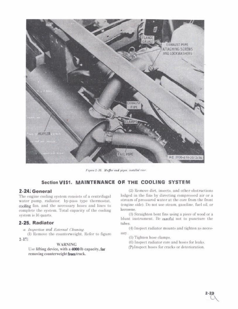
2-22. GeneralThe exhaust system is comprised of a muffler, exhaustpipe, and tailpipe. The muffler is attached to the insideof the left-hand frame member, adjacent to the engine.The exhaust pipe connects the muffler to the engineexhaust manifold. The tailpipe carries the exhaustgases from the muffler to the rear of the truck.
2-23. Muffler and Pipes
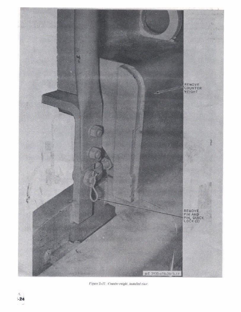
a. Removal. Refer to figure 2-16 and remove themuffler and pipes as follows:
(1) To remove the muffler, remove the exhaustpipe (2) below and loosen the clamp securing thetailpipe to the muffler. Lift out the muffler.
2-22

b. Removal. Refer to figure 2-18 and remove the (4) Disconnect the converter oil cooler lines atradiator as follows : the radiator.
(1) Remove the side panels and raise the seat. (5) Remove the radiator grille and panel.(2) Remove the radiator cap, open the drain (6) Remove the four screws (two on each side of
cocks and drain the cooling system. the radiator) that secure the radiator to the mounting(3) Disconnect upper and lower hoses from the bars.
radiator. (7) Remove radiator.
Figure 2-18. Radiator. installed view
2 - 2 5


(1) Drain a sufficient amount of coolant from theradiator to bring the level below that of the thermostathousing.
(2) Remove the 2 screws and lockwasher attachingthe outlet tube to the thermostat housing and movethe tube from the housing.
b. Testing.
ME 3930-618-20/2-24Figure 2-24. Testing thermostat (typical).
(1) Fill a container with sufficient water to coverthe thermostat.
(2) Suspend a reliable thermometer in the waterso the sensitive portion does not rest directly on thecontainer bottom or sides.
(3) Place the container on a stove or other heatsource. Stir the water occasionally for even heating.
(4) In the temperature range of 166°F to 165°Fthe thermostat should start to open and should becompletely open when the temperature is between185°F and 190°F.
(5) Lifting the thermostat into the colder tem-perature of the surrounding air should cause a pro-nounced closing action within a short time.
(6) Discard a thermostat that fails to pass theabove test.
c. Installation. Reverse procedure in a above.Attach the outlet tube securely and check for leakswith the engine operating.
2-29. Water Temperature Sending Unita. Inspect. Check to see if coolant is leaking around
sending unit. Run engine for ten minutes and see ifwater temperature dial shows an increase in tem-perature. If not, sending unit is probably defective.Replace a defective unit.
b. Removal. Refer to figure 2-23 and remove thewater temperature sending unit as follows :
(1) Drain a sufficient amount of coolant from theradiator to bring the level below that of the watertemperature sending unit.
(2) Disconnect wire going to unit.(34 Remove water temperature sending unit.
c. lnstallation. Reverse procedure in a above.Inspect for leaks.
2-30
Section IX. MAINTENANCE OF THE ELECTRICAL SYSTEM
2-30. GeneralThe electrical wiring diagram for the truck is shown infigure 1-3. The electrical system includes the Id-voltnegative ground battery, distributor, ignition coil,spark plugs, starter motor and starter motor solenoid,current and voltage regulator, horn circuit, lightssending units and gages, and wiring. The electricalgage, horn, and lighting circuits are protected byfuses. Fuses are located on the underside of the in-strument panel near the ignition switch.
2-31. Alternatora. Removal. Refer to figure 2-21 and remove the
alternator as follows :(1) Tag and disconnect wiring.(2) Remove bolt, washer, and nut in adjusting
strap.(3) Remove bolt and nut below alternator.(4) Remove alternator.
b. Installation. Reverse procedure in a above.
2-32. Voltage Regulatora. Test. The desired voltage regulator setting is
one which keeps the battery in a satisfactory state ofcharge (3/4 charge or more) without causing excessivebattery water usage.Either of the two conditions may persistently existwhich indicate the need for adjusting the regulator
setting: (1) Battery is being overcharged, (2) batteryremains undercharged.
b. Adjustments. Corrections should be made asfollows :
(1) If the battery uses too much water at the“normal” setting, reduce the voltage setting approxi-mately 0.3 volt and check for decreased battery waterusage over a reasonable period. If necessary, repeatthe process until the battery remains charged with aminimum use of water.
(2) If the battery is consistently undercharged(evidenced by inability to crank the engine) at thenormal setting, increase the voltage setting 0.3 voltsand check for improved condition over a reasonableservice period. If necessary, repeat this process untilthe battery remains charged with a minimum use ofwater. The external adjustment type regulator haspositive stops on the adjusting mechanism that willprohibit excessive high and low settings. To adjustthe voltage regulator setting of the external adjust-ment type regulator, remove the access plug from theregulator. Then for an undercharged battery insertscrewdriver into slot and turn clockwise one notch(0.3 volt) to increase the setting. For an overchargedbattery, turn counterclockwise one notch (0.3 volt)to decrease setting. Reference figure 2-25. Check foran improved battery condition over a service period ofreasonable length. If necessary repeat the above pro-cedure for a higher or lower setting.
2-31
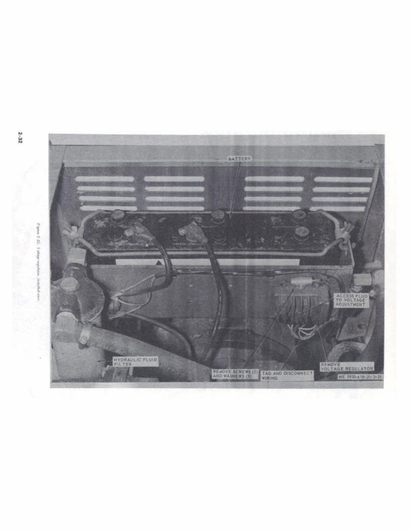

c. Removal. Refer to figure 2-25 and remove voltageregulator as follows:
(1) Disconnect and tag electrical leads.
(2) Remove the screws and washers securing theregulator to i ts mounting plate and remove theregulator.
d. Installation. Reverse procedure in c above.
2-33 . S ta t ing Motora. Removal. Refer to figure 2-26 and remove the
starter motor as follows :
(1) Remove the operator’s seat and the side panel.
(2) Disconnect and tag all electrical leads from thestarter motor.
Figure 2-26. Starter motor. installed view.
2-34. Distributor(3) Remove the bolts securing the starter motor
to the flywheel housing.
(4) Withdraw the starter motor from the flywheelhousing until the drive end clears the flywheel housing.Then tilt the commutator end-up and remove thestarter motor.
b. Installation.
(1) Reverse procedure in a above.
(2) If the drive mechanism is fully extended,mesh pinion gear with flywheel ring gear.
NOTEBecause of the offset torque and groove drive, the distributorcan be removed, overhauled and replaced without retimingthe engine. When removing the distributor, do not loosen orremove the advance arm. Remove distributor and advancearm as an assembly.
a. Removal. Refer to figure 2-27 and remove thedistributor as follows :
(1) Disconnect spark plug cables from the sparkplugs, ignition coil cable from the coil, and the primarylead from the distributor primary terminal.
(2) Remove the screw and washers from the ad-vance arm and lift the distributor from the drivehousing.
2 - 3 3


b. Disassembly. Refer to figure 2-28 and disassemblethe distributor in numerical disassembly sequence.
1 cap2 Rotor3 Cover4 Screw5 contact set6 Screw7 Bracket8 Capacitor
ME 3930-618-20/2-289 Screw
10 Plate, breaker11 Lead12 Grommet1 3 S h i m14 Washer15 P in , sp r ing16 Coupling
c. Cleaning and Inspection.(1) Clean all parts thoroughly and replace any
damaged or worn parts. Do not clean the cap, dustcover, rotor, condenser, insulator, or housing in de-greasing compound.
(2) Repair slightly worn or pitted contact pointswith a few strokes of a clean fine cut point file. Replacecontact points if worn or badly pitted.
(3) Check the breaker lever rubbing block forexcessive wear.
(4) Check the condenser for leakage. Replace itif testing is impractical.
(5) Check the distr ibutor cap and rotor forcracks, burning of contacts, or carbon streaks.
d. Assembly. Reverse procedure in b above.e. Installation. Reverse procedures in a above.f. Adjustments. Refer to paragraph 2-14 for ig-
nition timing adjustment.(1) Remove distributor cap rotor and dust cover.(2) Rotate the crankshaft until the breaker lever
rubbing block ix on a high spot on the cam, thus open-ing the contact, points to their maximum open position.
(3) Loosen the contact plate locking screw.(4) Turn the eccentric adjusting screw to obtain
the correct gap of 0.022 inch and tighten the lockingscrew.
(5)screw.
(6)cap.
Recheck the gap after tightening the locking
Install the dust, rover, rotor, and distributor
2-35. Spark PlugsSpark plugs and spark plug wires must always bemaintained in good condition and kept. free of dirtand grease. Replace any burned, cracked, broken, orotherwise unserviceable spark plugs.
a. Removal.(1) Disconnect wires at the spark plugs. Blow out
all dirt from the spark plug wells with compressed air.(2) Use a spark plug socket wrench and remove
the spark plugs. Make sure the socket fits correctly toavoid damaging the plugs.
(3) As each plug is removed make sure the coppergasket is also removed.
b. Cleaning.(1) Clean spark plugs by scraping excess carbon
and lead deposits off the electrodes and insulator body.(2) Sand blasting does not clean between the
electrodes and will ruin the glaze on the insulatormaterial if left in the sand blast machine too long.
(3) Using a file, file electrodes until square on flatat the gap surface.
Figure 2-28. Ignition distributor. exploded view.(4) Clean exposed insulator surface of all grease,
dirt or paint.
2-35

c. Adjusting gap. Adjust the gap by bending theoutside electrode. Never bend the center electrode.Use a round wire feeler gage for measuring. Adjustfor 0.025 inch gap.
d. Testing. After cleaning and adjusting the gap,test all spark plugs in a standard spark plug testingmachine. Discard all plugs that test unsatisfactorily.
e. Installation.
(1) Always use new copper gasket.
(2) Tighten plugs by hand and then torque to15-20 foot-pounds.
(3) Connect spark plug wires to the correct plugs.
2-36. Ignition Coila. Inspection. Inspect ignition coil to see if case is
cracked or if oil is leaking from case. Replace a defectiveignition coil.
b. Removal.(1) Tag and disconnect the wires going to the
ignition coil.(2) Loosen clamp holding ignition coil.(3) Remove coil.
c. Installation. Reverse procedure in b above.
2-37. Battery and Cablesa. Removal. Refer to figure 2-29 and remove the
battery as follows:(1) Remove the operator’s seat.(2) Remove the wingnuts from the holddown
studs and remove the battery holddown.(3) Remove both cables from the battery posts.
To prevent accidental damage to the battery posts orcable terminals, use a cable terminal puller tool toremove the cables.
(4) Tilt the battery towards the rear of the truckand lift it out of the battery tray.
Figure 2-29. Battery and cables. installed view.
b. Cleaning.(1) Clean the top of the battery, posts, and cable
terminals with a solution of baking soda and water.(2) Make sure that all fittercaps are tight to
prevent any solution from entering the cells.(3) After foaming stops. flush the battery and
cable terminals with clean, fresh water.c. Inspection and Testing.
(1) Inspect cables for broken strands, defectiveinsulation, or damaged terminals.
(2) Inspect the battery for cracks, breaks, orother defect’s,
(3) Take a specific gravity reading of the electro-lyte using a hydrometer. If the specific gravity readingis 1.225 or lower, recharge the battery. A fully chargedbattery will read from 1.265 to 1.290 specific gravity.
d. Installation. Reverse procedures in a above.Apply a coating of petroleum jelly to the battery postsbefore connecting the cable terminals.
2-38. Gages and InstrumentsAll gages and instruments are mounted on the instru-ment panel and may be removed by disconnecting thewiring from the individual gage or instrument and
2-36

removing the item from the instrument panel. Tag thewires for proper installation. Reference figure 1-3.
2-39. Lightsa. Headlight.
(1) Removal. Refer to figure 2-30 and remove asfollows :
(a) Unplug the wires at the connectors.(b) Unscrew the adjusting knob (4).(c) Remove the locknut (3).(d) Remove the light assembly (1), from the
mounting bracket (2).
Figure 2-30. Headlight. explosed view.
2 - 3 7

(2) Disassembly.(a) Pull the rubber bezel (7) from the base (5).(b) Loosen the terminal screws and disconnect
the wires from the lamp.(c) Using care, push the lamp (6) out of the
bezel.(3) Lamp replacement. The lamp can be replaced
with the light installed on the truck. Refer to (2) above.
b. Combination Rear Lamp.(1) Removal. Refer to figure 2-31 and remove as
follows :(a) Unplug the wires at the connectors.(b) Remove the nuts and washers securing the
light (1) to its mounting bracket and remove the light.
Figure 2-31. Combination rear light. exploded view.
(2) Disassembly.(a) Remove the lens retainer (2).(b) Remove the lens (3).(c) Remove the lamp (4) by pushing in slightly
and twisting counterclockwise.(3) Bulb replacement. The bulk can be replaced
with the light installed on the truck. Refer to (2) above.
2-40. Horn and Horn Relaya. General. The horn and horn relay are located
under the toe plate on the right-hand side. Pressingthe horn button actuates the horn relay. The hornrelay, when actuated, closes the battery-to-horncircuit. Use of the relay permits a shorter, more directconnection between the battery and horn. This resultsin higher voltage at the horn and avoids pulling fullcurrent through the horn button.
h. Test and Adjustments. In event of horn mal-function, always check to be sure that the battery isproducing full rated voltage before conducting thefollowing tests.
(1) If the horn produces a weak signal, proceedas follows :
2-38
(a) Connect a voltmeter between the hornterminal and ground and press the horn button.Observe the voltage reading on the voltmeter.
(b) If the voltage is between 0- and 10.7-volts,check for an open circuit, defective horn relay, poorwiring, or a shorted horn roil.
(2) If the horn signal is weak and the voltage atthe horn terminal is normal, attempt to increase volumewith the volume adjusting screw in the horn cover.Turn the screw in to increase volume : out to decreasevolume.
(3) If a defective horn relay is indicated: checkfor proper airgap, point opening, and closing voltagebefore replacing the relay. Correct settings are asfollows :
(a) Air gap (with points closed)- 0.020 inch.(b) Point opening -0.018 inch.(c) Closing voltage -8.3-10.2 volts.
c. Removal. Refer to figure 2-32 and remove thehorn and horn relay as follows:
(1) Remove the toe plate.(2) Disconnect all wires at the horn and the
horn relay.
(3) Remove the nut washer, securing the hornmounting bracket, and remove the horn.
(4) Remove the screw, nut, and washer attachingthe horn relay and remove the relay.
d. Installation. Reverse procedures in c above.
Figure 2-32. Horn and horn relay. installed view.
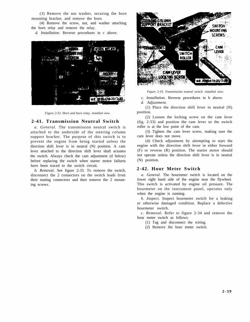
2-41. Transmission Neutral Switcha. General. The transmission neutral switch is
attached to the underside of the steering columnsupport bracket. The purpose of this switch is toprevent the engine from being started unless thedirection shift lever is in neutral (N) position. A camlever attached to the direction shift lever shaft actuatesthe switch. Always check the cam adjustment (d below)before replacing the switch when starter motor failureshave been traced to the switch circuit.
b. Removal. See figure 2-33. To remove the switch,disconnect the 2 connectors on the switch leads fromtheir mating connectors and then remove the 2 mount-ing screws.
Figure 2-33. Transmission neutral switch. installed view.
c. Installation. Reverse procedures in b above.d. Adjustment.
(1) Place the direction shift lever in neutral (N)position.
(2) Loosen the locking screw on the cam lever(fig. 2-33) and position the cam lever so the switchroller is at the low point of the cam.
(3) Tighten the cam lever screw, making sure thecam lever does not move.
(4) Check adjustment by attempting to start theengine with the direction shift lever in either forward(F) or reverse (R) position. The starter motor shouldnot operate unless the direction shift lever is in neutral(N) position.
2-42. Hour Meter Switcha. General. The hourmeter switch is located on the
lower right hand side of the engine near the flywheel.This switch is activated by engine oil pressure. Thehourmeter on the instrument panel, operates onlywhen the engine is running.
h. Inspect. Inspect hourmeter switch for a leakingor otherwise damaged condition. Replace a defectivehourmeter switch.
c. Removal. Refer to figure 2-34 and remove thehour meter switch as follows:
(1) Tag and disconnect the wiring.(2) Remove the hour meter switch.
2 - 3 9


Section X. MAINTENANCE OF THE TRANSMISSION
2-43. GeneralThe transmission consists of three major components,a torque converter, a hydraulically actuated clutchpack, and a single speed constant mesh transmission.
(7) After filling transmission with oil, check foroil leakage around the gasket area, tighten filtersufficient to stop leakage.
2-44. Transmission Oil Filtera. Removal of Filler Element.
(1) Operate transmission until oil temperaturereaches operating temperature (about 10-15 minutes).
(2) Use oil filter removing tool. unscrew anddiscard filter. See figure 2-12.
(3) Clean dirt and sediment from filter base. Besure all lint, etc., is removed if a rag is used to clean
parts.
b. Removal of Filter Assembly.(1) Refer to figure 2-12 and remove filter assembly
RR follows: Disconnect oil lines from fittings on filterbase. Tag lines to aid in reassembly. Plug the open endof oil lines to keep dirt out of lines and prevent leakageof oil from lines.
(2) Remove capscrews and washers securing filterbracket to engine block.
(3) Remove filter assembly.c. Installation of Filter Assembly. Reverse procedure
in b above. Service transmission as described in II above.
(4) Apply a light coat of oil to the rubber gasketon the filter. Screw filter to filter base until hand tight.
CAUTION
2-45. Transmission Torque ConverterServicing
Do not use removing tool to replace filter.
(5) Start engine and run engine for about 5minutes. With engine running and transmission inneutral (N) check transmission oil level with dipstick.
CAUTIONBe sure parking brake is set.
(6) Add transmission oil (prescribed on the lubri-cation order) until oil reaches full level on dipstick,about 1 quart.
CAUTION
Every 1000 hours remove torque converter andtransmission drain plug and drain. Remove spring andscreen, which are held in place by drain plug. Washscreen in SD before reinstalling. Access to converterdrain plug is gained through timing covers opening onengine flywheel housing. Rotate flywheel until drainplug is in opening, remove plug, and rotate flywheeluntil plug is aligned with drain opening at bottom offlywheel housing. Drain and install plugs. Fill trans-mission to FULL mark; operate transmission for5 minutes; check for leaks: check oil level and bringto FULL mark.
Do not overfill transmission, overfilling cancause damage to transmission seals.
Section XI. MAINTENANCE OF THE FRONT DRIVE AXLE
2-46. GeneralThe front axle consists of two components; the frontaxle assembly and the differential.
2-47. Front Axle Assembly ServicingEvery 50 hours, turn drive wheel until oil plugs are inposition 90° from bottom dead center. Remove plugsand check oil level. Add oil as necessary. Every 1000hours, turn drive wheels until oil plugs are at the
bottom. Remove plugs and drain all oil turn drivewheels until filter openings are at the top. See lubrica-tion order for quantity and weight of oil to be added.
2-48. Differential ServicingEvery 100 hours check oil level in differential. Everyl000 hours oil in differential is to be drained and re-filled. See lubrication order for quantity and weight ofoil to be used.
Section XII. MAINTENANCE OF THE REAR STEERING AXLE
2-49. GeneralThe rear axle consists of an axle and two wheels. SeeLubrication Order LO-3930-618-12.
2-50. Steering AxleEvery 50 hours the steering axle trunnions and kingpins will be lubricated. See lubrication order forlocation of grease fittings.
2 - 4 1
Section XIII. MAINTENANCE OF THE BRAKES
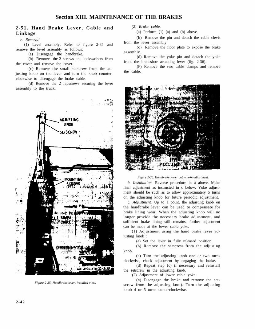
2-51 . Hand Brake Lever , Cab le andLinkage
a. Removal(1) Level assembly. Refer to figure 2-35 and
remove the level assembly as follows:(a) Disengage the handbrake.(b) Remove the 2 screws and lockwashers from
the cover and remove the cover.(c) Remove the small setscrew from the ad-
justing knob on the lever and turn the knob counter-clockwise to disengage the brake cable.
(d) Remove the 2 rapscrews securing the leverassembly to the truck.
(2) Brake cable.(a) Perform (1) (a) and (b) above.
(h) Remove the pin and detach the cable clevisfrom the lever assembly.
(c) Remove the floor plate to expose the brakeassembly.
(d) Remove the yoke pin and detach the yokefrom the brakeshoe actuating lever (fig. 2-36).
(P) Remove the two cable clamps and removethe cable.
Figure 2-36. Handbrake lower cable yoke adjustment.
b. Installation. Reverse procedure in a above. Makefinal adjustment as instructed in c below. Yoke adjust-ment should be such as to allow approximately 5 turnson the adjusting knob for future periodic adjustment.
c. Adjustment. Up to a point, the adjusting knob onthe handbrake lever can be used to compensate forbrake lining wear. When the adjusting knob will nolonger provide the necessary brake adjustment, andsufficient brake lining still remains, further adjustmentcan be made at the lower cable yoke.
(1) Adjustment using the hand brake lever ad-justing knob :
(a) Set the lever in fully released position.(b) Remove the setscrew from the adjusting
knob.(c) Turn the adjusting knob one or two turns
clockwise, check adjustment by engaging the brake.(d) Repeat step (c) if necessary and reinstall
the setscrew in the adjusting knob.(2) Adjustment of lower cable yoke.
(n) Disengage the brake and remove the set-screw from the adjusting knot). Turn the adjustingknob 4 or 5 turns conterclockwise.
Figure 2-35. Handbrake lever, installed view.
2-42

(b) Remove the floor plate and remove the pin (5) Remove the screws holding the master cylin-from the lower cable yoke. Loosen the yoke locknut der assembly to the inside of the frame and removefigure 2-36. the cylinder.
(c) Turn the yoke 3 or 4 turns clockwise toshorten the cable length.
(d) Install the yoke on the brake lever andcheck adjustment by engaging the brake. Readjust asnecessary to prevent the brakeshoes from draggingwhen disengaged.
(e) Tighten the yoke locknut and install thepin.
(f) Install and tighten the setscrew in theadjusting knob.
2-52 . Brake Peda l and L inkage Ad-jus tmentThe ideal pedal free play is %-inch. Too little freetravel will prevent the master cylinder piston fromreturning to full OFF position and the brakes willbegin to drag after several applications. Excessivefree travel will reduce the usable stroke of the mastercylinder. Refer to figure 2-37 and adjust as follows:
a. Remove the floor plates.b. Slowly depress the brake pedal and check for
1/2-inch free travel. Also observe push rod action.c. To obtain the proper free travel, loosen the
locknut on the clevis and then turn the adjusting nut.d. Tighten the locknut and reinstall the floor plates.
ME 3930-618-20/2-37
Figure 2-37. Brake pedal adjustment.
2-53. Brake Master Cylinder
a. Removal. Refer to figure 2-38 and remove themaster cylinder assembly as follows :
(1) Remove the floor plate.(2) Disconnect the electrical wires at the stop-
light switch.(3) Remove the power booster (para 2-54).(4) Remove the clevis pin holding the pushrod to
the brake pedal.
Figure 2-38. Brake master cylinder and brake power booster.
installed view
b. Installation. Reverse procedures in a above. Bleedthe brake hydraulic system as instructed in c below.
c. Bleeding the Brake Hydraulic System. The fluid inthe brake hydraulic system must form a “solid”column. To do this, the system must be bled of all airor other gases. Bleeding of the brake system is requiredeach time the system is drained and refilled with newfluid ; if some part of the system has been disconnectedfor any reason; if the fluid level in the master cylinderis allowed to decrease to a point where air enters thesystem; if the air has entered the system due to adefective master cylinder or wheel cylinders; or if thebrake pedal feels spongy. There is a bleeder screw oneach wheel cylinder and on the power booster. To bleedthe system, proceed as follows :
(1) Fill the master cylinder to the proper level(3/8- to 1/2-in. from the reservoir top).
(2) If a refiller or pressure bleeder is used, placethe proper adapter in the master cylinder fillercapopening and install the refiller or pressure bleeder.
(3) Install a bleeder hose on the bleeder screw ofeither wheel cylinder. Submerge the loose end of thehose in brake fluid in a glass jar.
(4) Open the bleeder screw one turn.
2 - 4 3

(5) If a pressure bleeder is used, permit the fluidto drain from the bleeder hose until no bubbles appearin the fluid. Then close the bleeder screw.
(6) If manual bleeding is being employed, slowlydepress the brake pedal to the stroke limit, close thebleeder screw, and then release. Repeat until nobubbles escape from the bleeder hose. Keep the pedaldepressed after the final stroke and quickly close thebleeder screw so that no air enters the system.
NOTEManual bleeding quickly depletes the fluid supply in thereservoir. Continually check the fluid level and keep thereservoir at least 1/2 full et all times or air will enter system.
(7) Repeat the bleeding procedure at the remain-ing wheel cylinder and then at the power boo&r.
(8) When the bleeder operation is complete refillthe master cylinder reservoir to the proper level.
CAUTIONFluid salvaged from the system during thebleeding operation is aerated and is no longersuitable for use in this system.
2-54. Brake Power Boostera. General. The brake power booster is connected
to the master cylinder outlet through a pipe nippleand is operated by pressure produced in the mastercylinder. It multiplies the pressure produced in themaster cylinder end applies this increased pressure tothe wheel cylinders, resulting in more positive braking.
b. Removal. Refer to figure 2-38 and remove thepower booster as follows :
(1) Remove the floor plate.(2) Disconnect the brake l ine at the power
booster.(3) Using an open-end wrench of the proper size,
hold the connecting nipple to the master cylinderwhile removing the power booster.
c. Installation.(1) Reverse procedures in b above.(2) Use a suitable thread compound on thread
connections and make sure connections are tight.(3) Bleed the brake system (para 2-53).
Section XIV. MAINTENANCE OF THE WHEELS
2-55. GeneralThe drive wheel rim and tire assembly consist of2 wheels, 2 tires, and tubes. The steer wheel assembliesconsist of a wheel, tire and tube, and bearings.
2-56. Drive Wheelsa. Removal.
(1) Raise the front of the truck so the wheelclears the floor. This may be done by tilting the mastto full backward position and inserting a block under
the mast assembly and then tilting the mast to thevertical position.
(2) Remove the 3-segment wedge ring (7) figure2-39.
(3) Slide the outer tire and rim assembly fromthe hub.
(4) Remove the rim spacer and then the innertire and rim assembly.
b. Installation. Reverse procedures in a above.
2-44

ME 3930-618-.20/2-39
1. Rim base2. Flap3. Tube4. Tire5. Spacer, rim
6. Ring, lock7. Ring, wedge8. Nut9. Stud
Figure 2-39. Drive wheel. rim. tire and tube. exploded view.
2-57. Steering Wheelsa. Removal.
(1) Raise the rear of the truck until the wheelsclear the floor. Block front wheels securely to preventthe truck from rolling.
(2) Remove the nuts and lockwashers attachingthe rims to the studs in the hub assembly (fig. 2-40).
(3) Pull the tire and rim assembly from thehub assembly.
b. Installation. Reverse procedures in a above.c. Tire and Tube Repair. If a tire is excessively
worn or badly damaged, replace it as follows :
(1) Remove the appropriate wheel.(2) Deflate the tube completely.(3) Remove the outer rim (drive wheel) from the
inner rim and remove the tire, tube and Hap.(4) To remove the steer wheel tire, tube, and
flap, remove the nuts and lockwashers and separatethe inner and outer rims.
(5) Replace or repair the defective tire, tube, orflap and reassemble in reverse order of removal.
(6) Install tire and rim assembly.(7) Inflate to proper pressure (100 psi).
2 - 4 5

Figure 2-40. Steer wheel. rim tire and tube exploded view.
2-58. Bearings and Seals (Steer WheelsOnly)
a. Removal.(1) Remove the steering wheel (para 2-57).(2) Remove the hub cap (fig, 2-40).(3) Remove the cotter pin (19) from the bearing
adjusting nuts (20) and remove the nut and washer.(4) Remove the outer bearing cone (2).(5) Slide the hub assembly (4) from the steer
axle spindle.(6) Remove the inner bearing cone and grease
retainer from the hub assembly.(7) Carefully top both bearing cups (3 and 5)
from the hub assembly.b. Cleaning and Inspection. Every 1000 hours wheel
bearings and races are to be lubricated. Clean bearings
and bearings races. Check for excessive wear ordamage. Check grease seals for leaks.
c. lnstallation and Adjustment.(1) Install cleaning cups with the taper to the
outside. Tap into place using a brass drift pin. Tapevenly around the edge of the cup. Use care to preventcup from binding.
(2) Lubricate wheel bearings with bearing grease.(3) Install the bearing cones and hub assemblies
in reverse order of rim oval. Hold the hub assembliesin position while installing the outer bearings.
(4) Install the washer and nut.(5) Rotate wheel six times in each direction while
torquing nut to 50 ft-lbs. Hack nut off to 0-ft-lb. thenretorque to 25 ft-lb. while, turning the wheel. Finallyhack nut off 30 minimum to 60 maximum andinstall the cotter pin.
Section XV. MAINTENANCE OF THE STEERING SYSTEM
2-59. General 2-60. Power SteeringThe steering system consists of the power steering unit,power steer cylinder, and the steering axle assembly.
a. Inspection. Inspect the
The steering axle is located beneath the engine at theleaks or damaged condition.
rear of the truck. The steering unit is mounted in thecylinder if damaged.
truck chassis in front of the operator.b. Removal. Refer to figure
power steering cylinder.
2-46
Cylindersteering cylinder, forReplace power steer
2-41 and remove the

(1) Disconnect hydraulic lines at the cylinder. (3) Loosen locknut.Plug lines to keep out foreign matter. (4) Rotate the cylinder to remove it from fitting
(2) Remove bolt, cotter pin, and pin and remove on steering axle pivot arm.cylinder from bracket.
2 - 4 7


Section XVI. MAINTENANCE OF THE BODY AND OVERHEAD GUARD
2-62. Seat and Backresta. Removal.
2-63. Overhead Guard
(1) To remove the seat cushion, lift it from theframe.
(2) To remove the backrest cushion, remove thescrews and lockwashers securing it to the frame.
b. Installation. Reverse procedures in a above.
a. Removal. The overhead guard is removed byremoving the screws, nuts, and lockwashers thatsecure it to the body.
b. Installation. Reverse procedure in a above.
Figure 2-44. Overhead guard. exploded view.
Section XVII. MAINTENANCE OF THE HYDRAULIC LIFT COMPONENTS
2-64 . Genera lAll l if t ing, steering powering of attachments isdone by hydraulic pressure. The hydraulic system iscomprised of an oil reservoir, a hydraulic pump coupledto the engine at the rear of the truck, dual controlvalve, lift and tilt cylinders, and the necessary hy-draulic lines and hoses. An oil filter is installed in thepump suction line for the purpose of removing con-taminants which may have entered the reservoir. Thelift cylinder is centrally mounted in the mast assembly.The tilt cylinders are attached to the truck frame andthe outer mast channels.
2-65. Hydraulic PumpInspect hydraulic pump for leaks or for any other
damage. Report a damaged condition to direct supportmaintenance.
2 - 5 0
2-66. Tilt Cylinder AdjustmentThe correct degree of tilt is 3° forward and 10° back-ward. Use a protractor to measure the degree of tilt.Proceed as follows :
NOTEMake sure the truck is standing level when checking tilt.
a. Tilt the mast to the limit of its backward stroke.b. Set the protractor for 3° and place it on the back
of the mast as shown in figure 2-45. The bubble in thelevel of the protractor will center if tilt is correct.
NOTECheck both right and left side of the mast and also make sureboth cylinders have come to the end of their stroke
c. If adjustment is necessary, tilt the mast to theforward position and loosen the screw (fig. 2-46) onthe tilt cylinder yoke. Using a wrench, turn the pistonrod by adjusting hex in or out of the cylinder yoke toobtain the correct tilt angle.

d. When the correct tilt angle is obtained, tightenthe screw on the yoke.
e. Correct forward tilt is automatically obtainedwhen the backward tilt is correct.
Figure 2-45. Checking mast tilt.
2-67. Lift Chainsa. Removal. The chains are attached at one end to
anchors on the lift cylinder and at the other end toanchors on the carriage assembly; Refer to figure 2-47and remove the chain as follows-:
(1) Lower the mast to its lower limits.(2) Attach a hoist to the carriage to relieve the
tension on the chains.(3) Remove the cotter pins and chain links from
the anchors on the carriage assembly.(4) Remove the cotter pins and chain links from
the anchors on the lift cylinder.(5) The chains are then free for removal.
Figure 2-46. Tilt cylinder adjustment.
2 - 5 1


2-70. Lines and FittingsInspect hydraulic lines for leaks or other damage.Inspect fittings to make sure they are tight. Replacedefective fittings.
2-71. Hydraulic Fluid FilterFilter element replacement. The filter element is apaper type and cannot be washed. If dirty, it must bereplaced.
a. Removal. Refer to figure 2-50 and proceed asfollows :
(1) Remove the seat and seat support.(2) Separate the shell assembly from the head
assembly.(3) Remove the element, from the shell assembly.
b. Cleaning and Inspection. Clean the head assemblyand shell assembly and inspect for defects.
c. Installation.(1) Install a new element in the shell assembly.(2) Position a new gasket on the shell assembly
and install on the head assembly. Tighten the attachingnut.
(3) Operate the system and check the filtercarefully for leaks. Figure 2.50. Micrin-type hydraulic fluid filter. installed view.
2 - 5 3

APPENDIX AREFERENCES
A-1. Fire ProtectionTB 5-4200-200-10 Hand Portable Fire Extinguishers Approved for Army Users
A-2. LubricationC9100-IL Identification List for Fuels, Lubricants, Oils and WaxesLO 10-3930-618-12 Lubrication Order; Truck, Lift Fork Allis-Chalmers, Model
FP60-24PS, Army Model MHE-213
A-3. Painting
TM 9-213 Painting Instruction for Field Use
A-4. Radio SuppressionTM 11-483 Radio Interference Suppression
A-5 . MaintenanceTB 750-651
TM 38-750TM 10-3930-618-10
TM 10-3930-618-20P
TM 9-6140-200-15
Use of Anti-Freeze Solution and Cleaning Compounds inEngine Cooling Systems
The Army Maintenance Management SystemOperator’s Manual for Truck, Lift Fork, Army Model
MHE 213Organizational Maintenance Repair Parts Manual for Truck,
Lift Fork, Army Model MHE-213Operator and Organizational, Field and Depot Maintenance :
Storage Batteries, Lead Acid Type
A-6. Shipment and StorageTB 740-97-2 Preservation of USAMEC Mechanical Equipment for Ship-
ment and Storage
TM 740-90-1 Administrative Storage of Equipment
A-7. Destruction of Army Material to Prevent Enemy UseTM 750-244-3 Procedures for Destruction of Equipment to Prevent
Enemy Use
A-1


APPENDIX BMAINTENANCE ALLOCATION CHART
Section I. INTRODUCTION
B-l . Generala. This section provides a general explanation of all
maintenance and repair functions authorized at variousmaintenance levels.
b. Section II designates overall responsibility forthe performance of maintenance functions on theidentified end item or component. The implementationof the maintenance functions upon the end item orcomponent will be consistent with the assignedmaintenance functions.
c. Section III. Not Applicable.d. Section IV. Sot Applicable.
B-2. Explanation of Columns in Sec-tion II
a. Group Number. Column (1). The assembly groupis a numerical group assigned to each assembly in a topdown breakdown sequence. The applicable assemblygroups are listed on the MAC in disassembly sequencebeginning with the first assembly removed in a topdown disassembly sequence.
b. Functional Group. Column (2). This columncontains a brief description of the components of eachassembly group.
c. Maintenance Functions. Column (3). This columnlists the various maintenance functions (A through K)and indicates the lowest maintenance level authorizedto perform these functions. The symbol designationsfor the various maintenance levels are as follows:C-Operator or crewO-Organizational maintenanceF--Direct support maintenanceH-General support maintenanceD-Depot maintenance
The maintenance functions are defined as follows :A-Inspect. To determine serviceability of an item
by comparing its physical, mechanical, andelectrical characterist ics with establishedstandards.
R-Test. To verify serviceability and detectelectrical or mechanical failure by use of test,equipment.
C-Service. To clean, to preserve, to charge, and toadd fuel, lubricants, cooling agents, and air.
D-Adjust. To rectify to the extent necessary tobring into proper operating range.
E-Align. To adjust specified variable elements ofan item to bring to optimum performance.
F--Calibrate. To determine the corrections to bemade in the readings of instruments or testequipment used in precise measurement. Con-sists of the comparison of two instruments, oneof which is a certified standard of knownaccuracy, to detect and adjust any discrepancyin the accuracy of the instrument being com-pared with the certified standard.
G--Install. To set up for use in an operationalenvironment such as an emplacement, site, orvehicle.
H-Replace. To replace unserviceable items withserviceable like items.
I-Repair. Those maintenance operations neces-sary to restore an item to serviceable conditionthrough correction of material damage or aspecific failure. Repair may be accomplished ateach level of maintenance.
J-K--Overhaul/Rebuild. The disassembly, test, andinspection of the operating components andthe basic structure to determine and accomplishthe necessary rework, rebuild, replacement, andservicing to obtain the desired performance.Overhaul, rework, and rebuild are synonymous.
d. Tools and Equipment. Column (4). This column isprovided for referencing by code the special tools andtest equipment required to perform the maintenancefunctions.
e. Remarks. Column (5). This column is providedfor referencing by code the remarks pertinent to themaintenance functions.
B-1

01
02
03
04
0 5
06
07
08
09
10
11
12
13
14
15
16
17
18
1920
21
22
23
24
Section II. MAINTENANCE ALLOCATION CHART
LIGHTS
O V E R H E A D G U A R D A N D S I D E P A N E L L A T C H OFORKS AND CARRIAGE
car r iage
M A S T A N D L I F T C Y L I N D E R
S E A T , H O O D A N D S I D E P A N E L S . 0C O U N T E R W E I G H T , F E N D E R S A N D F L O O R P L A T E S 0R A D I A T O R . T R A N S M I S S I O N O I L F I L T E R A N D L I N E S
Rad ia to r CFilter, Oil.
INSTRUMENT PANEL
Gages; Switches 0Fuse: Relay 0
T I L T C Y L I N D E R , L I N E S A N D F I T T I N G S
Cylinder, Tilt
Lines and Fit t ings. 0B A T T E R Y , H O R N A N D L E A D S
Bat t e ry
A l R C L E A N E R CA C C E L E R A T O R P E D A L A N D L I N K A G E 0B R A K E A N D I N C H I N G C O N T R O L S
REGULATOR AND CAPACITOR
Regu la to r FM A S T E R C Y L I N D E R A N D B R A K E B O O S T E R
Cylinder, Master 0Booster, Brake 0Lines and Fittings. 0
S H I F T I N G C O N T R O LSwitch
HYDRAULIC PUMP. 0ALTERNATOR F
T A R T E R . FM U F F L E R A N D E X H A U S T P I P E . . 0ENGINE AND MOUNTSEngine Assembly 0
CARBURETOR 0M A N I F O L D A N D B R E A T H E R . 0
OIL F I L T E R
H
0
F
0
FF
0
c
C
0
0
C
0
0
0F
F
0
0
O
F
F
H
F
J
H
H
D
(5)
Remarks
OO
F
F
OO
O
O
O
O
F
O
O
OO
O
OOO
FO
F O
O
O
F
O
O O
FF
FF
F
OF

B-3
Section II. MAINTENANCE ALLOCATION CHART
OO
O
O
OO
O
O
O
C
O
O
O
O
F
O
O
OF
O
O
O
O
O
F
FF
F
F
F
H
F
H
F
H
F
F
O
OF
FOGear Assembly, Steering 0
Cylinder, Steering.
2 5 F U E L P U M P A N D F I L T E RP u m p , F u e l
F i l t e r , F u e l
26 T H E R M O S T A T A N D H O U S I N GThermostat
27 G O V E R N O R .
2 8 W A T E R P U M P A N D F A NBelt, FanPump, Water
29 D I S T R I B U T O R A N D W I R I N G
DistributorI g n i t i o n C o i l
Spark Plug
3 0 C Y L I N D E R H E A D C O V E R A N D R O C K E R A R M S
Rocker Arm
31 C Y L I N D E R H E A D A N D V A L V E SCylinder Head, Assy
Valves, Engine
32 O I L P A N A N D O I L P U M P
P u m p , O i l
33 F L Y W H E E L A N D H O U S I N G
Flywheel Assembly
34 T I M I N G G E A R C O V E R
3 5 C R A N K S H A F T , P I S T O N A N D C O N N E C T I N G R O DP u l l e y , C r a n k s h a f t
3 6 C A M S H A F T
Gear, Camshaft
37 C Y L I N D E R B L O C K
38 T R A N S M I S S I O N A N D C O N V E R T E R
Torque Converter
Transmission Assembly
3 9 P R O P E L L E R S H A F T
4 0 P A R K I N G B R A K E A N D L E V E R
Lever: Cable, Hand Brake.
Shoe, Brake
41 P O W E R S T E E R I N G G E A R A N D C Y L I N D E R A S S E M B L Y
F
O
F
F
F
H
H
0
F
0
F
F
H
H DF
F
OO
O
0
F
CC
0
0
F
F
H
O
FO

B-4 Section II. MAINTENANCE ALLOCATION CHART
4 2
4 3
4 4
4 5
4 6
4 7
4 8
H Y D R A U L I C R E S E R V O I R F I L T E R , L I N E S A N D F I T T I N G S
Filter, Hydraulic Fluid
Tank, Hydraulic Fluid.
Lines and Fit t ings 0
H Y D R A U L I C C O N T R O L V A L V E .
F U E L T A N K
S T E E R I N G A X L E A N D W H E E L
Steering AxleDrag Link 0
Tie Rod 0
Tires and Tubes 0F R O N T W H E E L S 0
Tires and Tubes 0
D R I V E A X L E A N D B R A K E S
Brake Shoes
Drive Axle
FRAME
0
0
C
0
0
0
F
0
0
0
0
0
0F
0
F
0
0
0
F
0
F
F
H
F
F
F
0
0
0
F

I N D E X
Paragraph
A I (Cont’d)
Accelerator Pedal Linkage. . . . . . . . . . . . . . . . .Air Cleaner. Carburetor . . . . . . . . . . . . . . . . . . . .Alternator . . . . . . . . . . . . . . . . . . . . . . . . . . . . . . .
B
2-202-162-31
2-202-162-31
IgnitionTiming . . . . . . . . . . . . . . . . . . . . . . . . . . . . 2-14lnspection and Servicing the Equipment . . . . . . . 2-1
L
Battery and Cables . . . . . . . . . . . . . . . . . . . . . . .Bearings and Wheels (steering wheels only).Brake Master Cylinder. . . . . . . . . . . . . . . . . . . .Brake Pedal and Linkage. . . . . . . . . . . . . . . . .Brake Power Booster . . . . . . . . . . . . . . . . . . . . .Breather Lines . . . . . . . . . . . . . . . . . . . . . . . . . .
2-372-582-532-522-542-9
2-362-462-433-432-442-12
Lift Chain. . . . . . . . . . . . . . . . . . . . . . . . . . . . . . . . . 2-67Lights . . . . . . . . . . . . . . . . . . . . . . . . . . . . . . . . . . . . . 2-39Lines and Fittings. . . . . . . . . . . . . . . . . . . . . . . . . . 2-70
M
Manifold Assembly . . . . . . . . . . . . . . . . . . . . . . . . . . 2-11 2-13Muffler and Pipes . . . . . . . . . . . . . . . . . . . . . . . . . . . 2-22 2-22
C
Carburetor . . . . . . . . . . . . . . . . . . . . . . . . . . . . . .Carburetor Air Cleaner. . . . . . . . . . . . . . . . . . .Compression Test . . . . . . . . . . . . . . . . . . . . . . . .Cooling System . . . . . . . . . . . . . . . . . . . . . . . . . .
D
Description and Data . . . . . . . . . . . . . . . . . . . .Differences in Models . . . . . . . . . . . . . . . . . . . .Differential Servicing . . . . . . . . . . . . . . . . . . . .Distributor. . . . . . . . . . . . . . . . . . . . . . . . . . . .Drive Wheels. . . . . . . . . . . . . . . . . . . . . . . . . .
E
Electrical System . . . . . . . . . . . . . . . . . . . . .Engine . . . . . . . . . . . . . . . . . . . . . . . . . . . . . .Exhaust System . . . . . . . . . . . . . . . . . . . . . .
F
Fan and Alternator Belt . . . . . . . . . . . . . .Forms and Records. . . . . . . . . . . . . . . . . .Front Axle . . . . . . . . . . . . . . . . . . . . . . . . . .Front Axle Assembly Servicing . . . . . . . .Fuel Filter . . . . . . . . . . . . . . . . . . . . . . . . . .Fuel Pump. . . . . . . . . . . . . . . . . . . . . . . . .Fuel System. . . . . . . . . . . . . . . . . . . . . . . .Fuel Tank . . . . . . . . . . . . . . . . . . . . . . . . . .
G
Cages and Instruments . . . . . . . . . . . . . . .Governor . . . . . . . . . . . . . . . . . . . . . . . . . . . .
H
Hand Brake Lever, Cables and Linkage. .Horn and Horn Relay.. . . . . . . . . . . . . . . .Hourmeter Switch. . . . . . . . . . . . . . . . . . . .Hydraulic Fluid Filter . . . . . . . . . . . . . . . . .Hydraulic Fluid Tank. . . . . . . . . . . . . . . . .Hydraulic Fluid Tank Breather . . . . . . . . .Hydraunc Litt Components. . . . . . . . . . . .Hydraulic Pump . . . . . . . . . . . . . . . . . . . . . .
I
2-512-402-422-712-682-692-642-65
Identification and Tabulated Data. . . . . . .Ignition Coil. . . . . . . . . . . . . . . . . . . . . . . . . .
2-17 2-182-16 2-162-12 2-142-24 2-23
1-31-52-482-342-56
2-30 2-312-7 2-82-22 2-22
2-26 2-261-2 1-42-46 2-412-47 2-412-18 2-182-18 2-182-15 2-162-21 2-21
2-38 2-362-19 2-20
l - 42-36
Page
1-41-62-412-332-44
2-422-382-392-532-522-522-502-50
1-42-36
Paragraph
OOil Filter . . . . . . . . . . . . . . . . . . . . . . . . . . . . . . . . . . 2-10Overhead Guard . . . . . . . . . . . . . . . . . . . . . . . . . . . . 2-63
P
Power Steering Cylinder. . . . . . . . . . . . . . . . . . . . . 2-60Preventive Maintenance Checks and Services
(General) . . . . . . . . . . . . . . . . . . . . . . . . . . . . . . . . 2-5Preventive Maintenance Checks and Services
(Quarterly). . . . . . . . . . . . . . . . . . . . . . . . . . . . . . 2-8
RRadiator. . . . . . . . . . . . . . . . . . . . . . . . . . . . . . . . . . 2-25Bear Axle . . . . . . . . . . . . . . . . . . . . . . . . . . . . . . . . . 2-49
SScope . . . . . . . . . . . . . . . . . . . . . . . . . . . . . . . . . . . . . 1-1Seat and Backrest . . . . . . . . . . . . . . . . . . . . . . . . . . 2-432Spark Plugs . . . . . . . . . . . . . . . . . . . . . . . . . . . . . . . . 2-35Special Tools and Equipment . . . . . . . . . . . . . . . . . 2-3Starting Motor. . . . . . . . . . . . . . . . . . . . . . . . . . . . . 2-33Steering Axle. . . . . . . . . . . . . . . . . . . . . . . . . . . . . . 2-50Steering Wheels. . . . . . . . . . . . . . . . . . . . . . . . . . . . 2-57Steering System. . . . . . . . . . . . . . . . . . . . . . . . . . . . 2-59
TThermostat . . . . . . . . . . . . . . . . . . . . . . . . . . . . . . . . 2-28Tie Rods . . . . . . . . . . . . . . . . . . . . . . . . . . . . . . . . . . 2-61Tools and Equipment. . . . . . . . . . . . . . . . . . . . . . . 2-2Transmission . . . . . . . . . . . . . . . . . . . . . . . . . . . . . . . 2-43Transmission Neutral Switch . . . . . . . . . . . . . . . . . 2-41Transmission Oil Filter . . . . . . . . . . . . . . . . . . . . . . 2-44Transmission Torque Converter Servicing. . . . . . 2-46
V
Vacuum Test . . . . . . . . . . . . . . . . . . . . . . . . . . . . . . . 2-13Valves . . . . . . . . . . . . . . . . . . . . . . . . . . . . . . . . . . . . 2-8Voltage Regulator. . . . . . . . . . . . . . . . . . . . . . . . . . 2-32
WWater Pump . . . . . . . . . . . . . . . . . . . . . . . . . . . . . . . 2-27Water Temperature Sending Unit. . . . . . . . . . . . 2-29Wheels . . . . . . . . . . . . . . . . . . . . . . . . . . . . . . . . . . . . 2-55
Page
2-142-1
2-512-372-53
2-122-50
2-46
2-1
2-1
2-232-41
1-12-502-352-12-332-412-452-46
2-292-492-12-412-392-412-41
2-142-122-31
2-282-302-44
I - 1

By Order of the Secretary of the Army :
Official :KENNETH G. WICKHAM,Major General, United States Army,The Adjutant General.
W. C. WESTMORELAND,General, United States Army,Chief of Staff.
Distribution :To be distributed in accordance with DA Form 12-25, Section I, (qty rqr block No. 194) Organizational mainte-
nance requirements for Truck, Fork Lift, Gasoline.
U.S. GOVERNMENT PRINTING OFFICE: 1971-431104/5184


TM 10-3930-618-20 TRUCJ, LIFT FORK-1971
P i n : 0 2 8 3 0 1 - 0 0